Embed Size (px)
Citation preview
Alulineartechnik AG
Alulin
ALUMINIUMRAIL GUIDES
SWISS MADE
L I G H T W E I G H T S T A I N L E S S I N T E R C H A N G E A B L E
Берг АБ e-mail: [email protected] тел. (495) 228-06-21, факс (495) 223-30-71www.bergab.ru
© Copyright by Alulineartechnik AGThe contents of this publication are the copyright of the publisher and may not be reproduced (even extracts) unless prior written permission is granted.Every care has been taken to ensure the accuracy of the information contained this publication but no liability can be accepted for any loss or damage weather direct, indirect or consequential arising out of use of the information contained herein.Specifications are subject to change without notice and without any obligation on the part of the manufacturer.
Берг АБ e-mail: [email protected] тел. (495) 228-06-21, факс (495) 223-30-71www.bergab.ru
3
Contents
Generals
Introduction
Accuracy
Mounting
Dimensioning
Lubrication Concept
. . . . . . . . . . . . . . . . . . . . . . . . . . . . . 4
. . . . . . . . . . . . . . . . . . . . . . . . . . . . . 5
. . . . . . . . . . . . . . . . . . . . . . . . . . . . . 6
. . . . . . . . . . . . . . . . . . . . . . . . . . . . . 7
. . . . . . . . . . . . . . . . . . . . . . . . . . . . . 8
. . . . . . . . . . . . . . . . . . . . . . . . . . . . . 9
. . . . . . . . . . . . . . . . . . . . . . . . . . . . 10
. . . . . . . . . . . . . . . . . . . . 11
Page
Runner Block Flange
Runner Block Standard, high
Aluminium Rail Guide with Niro Steel reinforcement
Measure Scale
. . . . . . . . . . . . . . . . . . . . . . . . . . . . 12
. . . . . . . . . . . . . . . . . . . . . . . . . . . . 12
. . . . . . . . . . . . . . . . . . . . . . . . . . . . 13
. . . . . . . . . . . . . . . . . . . . . . . . . . . . 13
Seal Unit
Lube Units with sealing function
Lubricating Nipple
Hydraulic-type lube nipple
Accessories
Берг АБ e-mail: [email protected] тел. (495) 228-06-21, факс (495) 223-30-71www.bergab.ru
4
Introduction
Product Overview
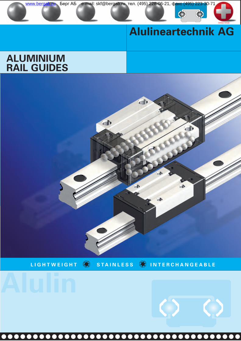
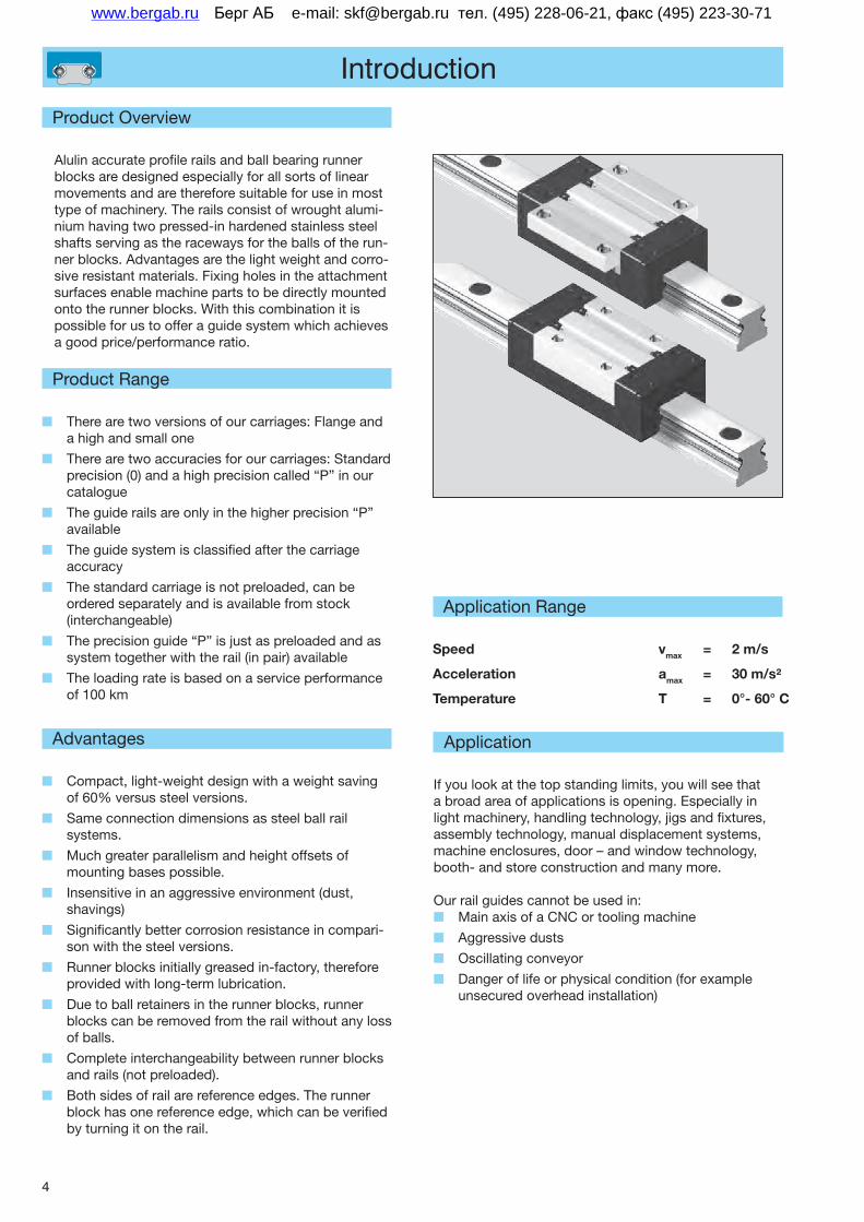
Alulin accurate profile rails and ball bearing runner blocks are designed especially for all sorts of linear movements and are therefore suitable for use in most type of machinery. The rails consist of wrought alumi-nium having two pressed-in hardened stainless steel shafts serving as the raceways for the balls of the run-ner blocks. Advantages are the light weight and corro-sive resistant materials. Fixing holes in the attachment surfaces enable machine parts to be directly mounted onto the runner blocks. With this combination it is possible for us to offer a guide system which achieves a good price/performance ratio.
Advantages
Q Compact, light-weight design with a weight saving of 60% versus steel versions.
Q Same connection dimensions as steel ball rail systems.
Q Much greater parallelism and height offsets of mounting bases possible.
Q Insensitive in an aggressive environment (dust, shavings)
Q Significantly better corrosion resistance in compari-son with the steel versions.
Q Runner blocks initially greased in-factory, therefore provided with long-term lubrication.
Q Due to ball retainers in the runner blocks, runner blocks can be removed from the rail without any loss of balls.
Q Complete interchangeability between runner blocks and rails (not preloaded).
Q Both sides of rail are reference edges. The runner block has one reference edge, which can be verified by turning it on the rail.
Application Range
Speed
Acceleration
Temperature
vmax = 2m/s
amax = 30m/s²
T = 0°-60°C
Product Range
Q There are two versions of our carriages: Flange and a high and small one
Q There are two accuracies for our carriages: Standard precision (0) and a high precision called “P” in our catalogue
Q The guide rails are only in the higher precision “P” available
Q The guide system is classified after the carriage accuracy
Q The standard carriage is not preloaded, can be ordered separately and is available from stock (interchangeable)
Q The precision guide “P” is just as preloaded and as system together with the rail (in pair) available
Q The loading rate is based on a service performance of 100 km
Application
If you look at the top standing limits, you will see that a broad area of applications is opening. Especially in light machinery, handling technology, jigs and fixtures, assembly technology, manual displacement systems, machine enclosures, door – and window technology, booth- and store construction and many more.
Our rail guides cannot be used in: Q Main axis of a CNC or tooling machine
Q Aggressive dusts
Q Oscillating conveyor
Q Danger of life or physical condition (for example unsecured overhead installation)
Берг АБ e-mail: [email protected] тел. (495) 228-06-21, факс (495) 223-30-71www.bergab.ru
5
Accuracy
Carriages in standard precision (stocked products)
For normal applications we recommend a combination of carriage and rail without preload. With the standard precision it will have a tolerance of µm between the rail and carriage. It is possible to order just the rail or carriage separately (interchangeable and in stock). An example for a runner block flange without preload: FNS-1500.
Deviation of parallelism
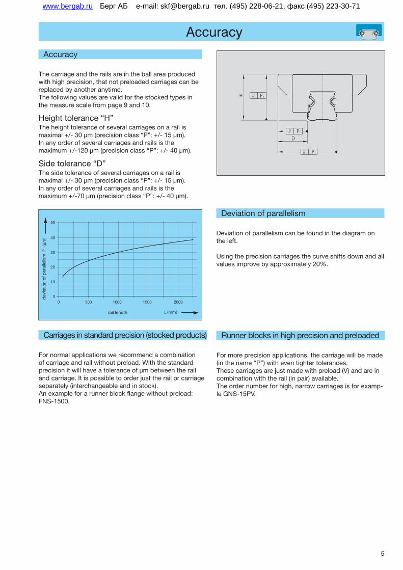
Deviation of parallelism can be found in the diagram on the left.
Using the precision carriages the curve shifts down and all values improve by approximately 20%.
0 500 1000 1500 20000
10
20
30
40
50
rail length
dev
iatio
n of
par
alle
lism
H P1
P1
D
P1
Accuracy
The carriage and the rails are in the ball area produced with high precision, that not preloaded carriages can be replaced by another anytime. The following values are valid for the stocked types in the measure scale from page 9 and 10.
Height tolerance “H”The height tolerance of several carriages on a rail is maximal +/- 30 µm (precision class “P”: +/- 15 µm). In any order of several carriages and rails is the maximum +/-120 µm (precision class “P”: +/- 40 µm).
Side tolerance “D”The side tolerance of several carriages on a rail is maximal +/- 30 µm (precision class “P”: +/- 15 µm). In any order of several carriages and rails is the maximum +/-70 µm (precision class “P”: +/- 40 µm).
Runner blocks in high precision and preloaded
For more precision applications, the carriage will be made (in the name “P”) with even tighter tolerances. These carriages are just made with preload (V) and are in combination with the rail (in pair) available. The order number for high, narrow carriages is for examp-le GNS-15PV.
Берг АБ e-mail: [email protected] тел. (495) 228-06-21, факс (495) 223-30-71www.bergab.ru
6
General Mounting Instructions
Parallelism
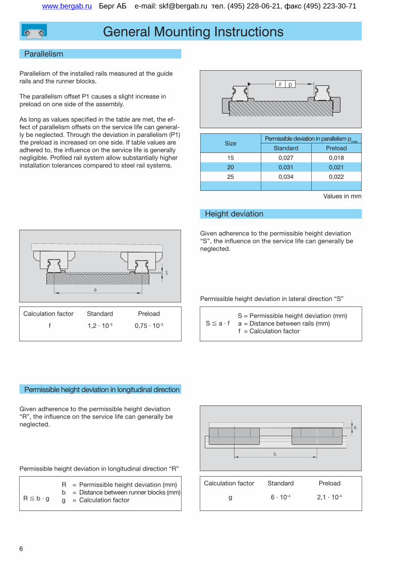
Parallelism of the installed rails measured at the guide rails and the runner blocks.
The parallelism offset P1 causes a slight increase in preload on one side of the assembly.
As long as values specified in the table are met, the ef-fect of parallelism offsets on the service life can general-ly be neglected. Through the deviation in parallelism (P1) the preload is increased on one side. If table values are adhered to, the influence on the service life is generally negligible. Profiled rail system allow substantially higher installation tolerances compared to steel rail systems.
S a · f
Calculation factor Standard Preload
f 1,2 · 10-3 0,75 · 10-3
S = Permissible height deviation (mm) a = Distance between rails (mm) f = Calculation factor
S
a
Height deviation
Given adherence to the permissible height deviation “S”, the influence on the service life can generally be neglected.
Permissible height deviation in lateral direction “S”
Permissible height deviation in longitudinal direction
Given adherence to the permissible height deviation “R”, the influence on the service life can generally be neglected.
R b · g
R = Permissible height deviation (mm)b = Distance between runner blocks (mm)g = Calculation factor
R
b
Calculation factor Standard Preload
g 6 · 10-4 2,1 · 10-4
Permissible height deviation in longitudinal direction “R”
II p
SizePermissible deviation in parallelism pmax
Standard Preload
15 0,027 0,018
20 0,031 0,021
25 0,034 0,022
Values in mm
Берг АБ e-mail: [email protected] тел. (495) 228-06-21, факс (495) 223-30-71www.bergab.ru
7
Lay out design
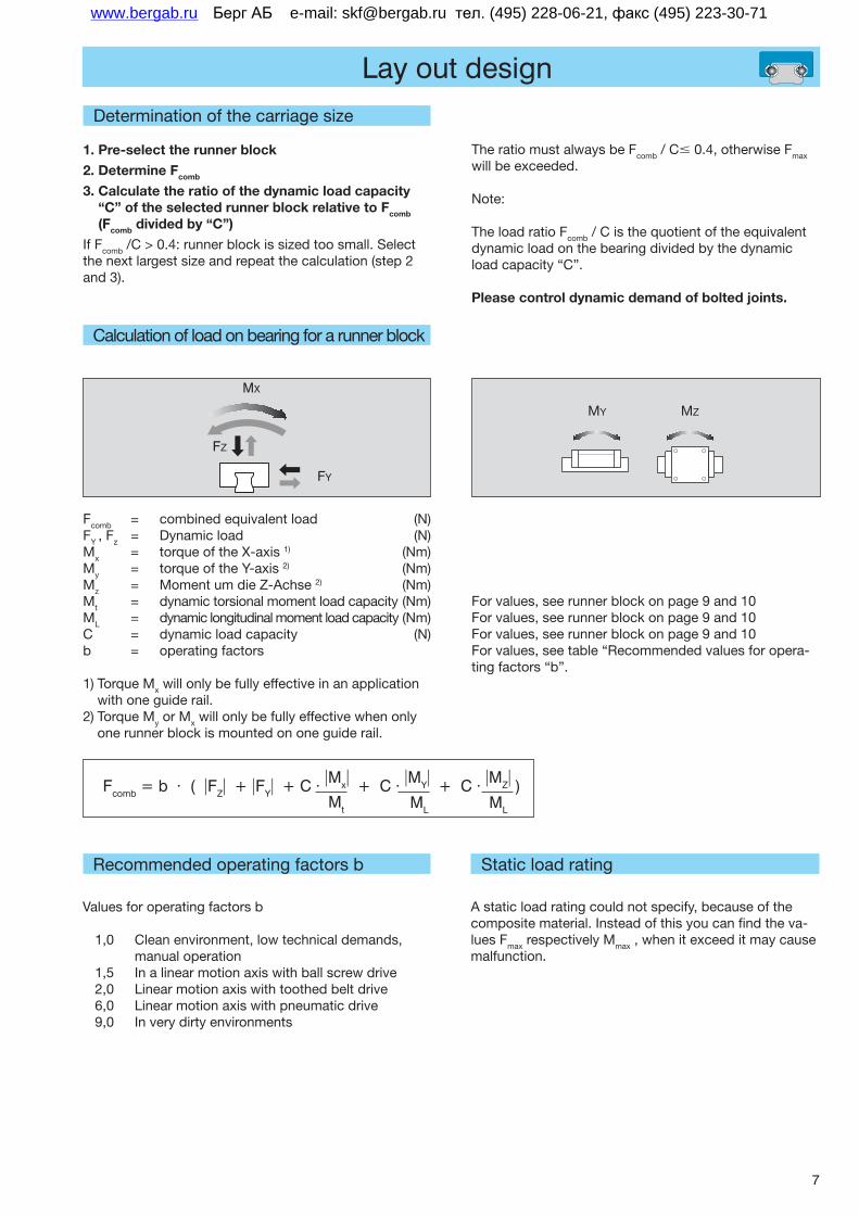
Determination of the carriage size
1. Pre-select the runner block
2. Determine Fcomb
3. Calculate the ratio of the dynamic load capacity “C” of the selected runner block relative to Fcomb (Fcomb divided by “C”)
If Fcomb /C > 0.4: runner block is sized too small. Select the next largest size and repeat the calculation (step 2 and 3).
Fcomb = combined equivalent load (N)FY , Fz = Dynamic load (N)Mx = torque of the X-axis 1) (Nm)My = torque of the Y-axis 2) (Nm)Mz = Moment um die Z-Achse 2) (Nm)Mt = dynamic torsional moment load capacity (Nm)ML = dynamic longitudinal moment load capacity (Nm)C = dynamic load capacity (N)b = operating factors
1) Torque Mx will only be fully effective in an application with one guide rail.
2) Torque My or Mx will only be fully effective when only one runner block is mounted on one guide rail.
Calculation of load on bearing for a runner block
For values, see runner block on page 9 and 10For values, see runner block on page 9 and 10For values, see runner block on page 9 and 10For values, see table “Recommended values for opera-ting factors “b”.
The ratio must always be Fcomb / C 0.4, otherwise Fmax will be exceeded.
Note:
The load ratio Fcomb / C is the quotient of the equivalent dynamic load on the bearing divided by the dynamic load capacity “C”. Please control dynamic demand of bolted joints.
Fcomb = b · ( FZ + FY + C · Mx + C · MY + C · MZ )Mt ML ML
Recommended operating factors b
Values for operating factors b
1,0 Clean environment, low technical demands, manual operation
1,5 In a linear motion axis with ball screw drive2,0 Linear motion axis with toothed belt drive6,0 Linear motion axis with pneumatic drive9,0 In very dirty environments
MY MZ
F
MX
FY
FZ
Static load rating
A static load rating could not specify, because of the composite material. Instead of this you can find the va-lues Fmax respectively Mmax , when it exceed it may cause malfunction.
Берг АБ e-mail: [email protected] тел. (495) 228-06-21, факс (495) 223-30-71www.bergab.ru
8
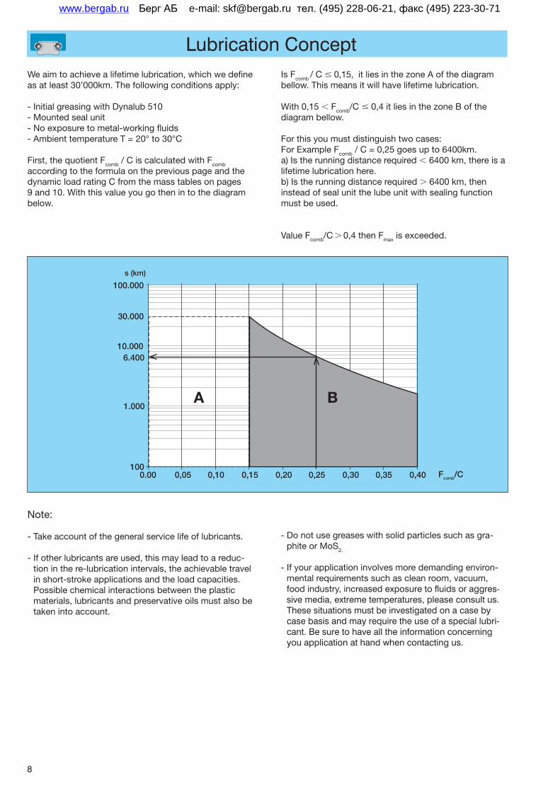
Lubrication ConceptWe aim to achieve a lifetime lubrication, which we define as at least 30’000km. The following conditions apply:
- Initial greasing with Dynalub 510- Mounted seal unit- No exposure to metal-working fluids- Ambient temperature T = 20° to 30°C
First, the quotient Fcomb / C is calculated with Fcomb according to the formula on the previous page and the dynamic load rating C from the mass tables on pages 9 and 10. With this value you go then in to the diagram below.
Is Fcomb / C 0,15, it lies in the zone A of the diagram bellow. This means it will have lifetime lubrication.
With 0,15 Fcomb/C 0,4 it lies in the zone B of the diagram bellow.
For this you must distinguish two cases:For Example Fcomb / C = 0,25 goes up to 6400km.a) Is the running distance required 6400 km, there is a lifetime lubrication here. b) Is the running distance required 6400 km, then instead of seal unit the lube unit with sealing function must be used.
Value Fcomb/C 0,4 then Fmax is exceeded.
Note:
- Take account of the general service life of lubricants.
- If other lubricants are used, this may lead to a reduc-tion in the re-lubrication intervals, the achievable travel in short-stroke applications and the load capacities. Possible chemical interactions between the plastic materials, lubricants and preservative oils must also be taken into account.
- Do not use greases with solid particles such as gra-phite or MoS2.
- If your application involves more demanding environ-mental requirements such as clean room, vacuum, food industry, increased exposure to fluids or aggres-sive media, extreme temperatures, please consult us. These situations must be investigated on a case by case basis and may require the use of a special lubri-cant. Be sure to have all the information concerning you application at hand when contacting us.
BA
100.000
30.000
0.00 0,05 0,10 0,15 0,20 0,25 0,30 0,35 0,40
10.0006.400
1.000
100
s(km)
Fcomb/C
Берг АБ e-mail: [email protected] тел. (495) 228-06-21, факс (495) 223-30-71www.bergab.ru
9
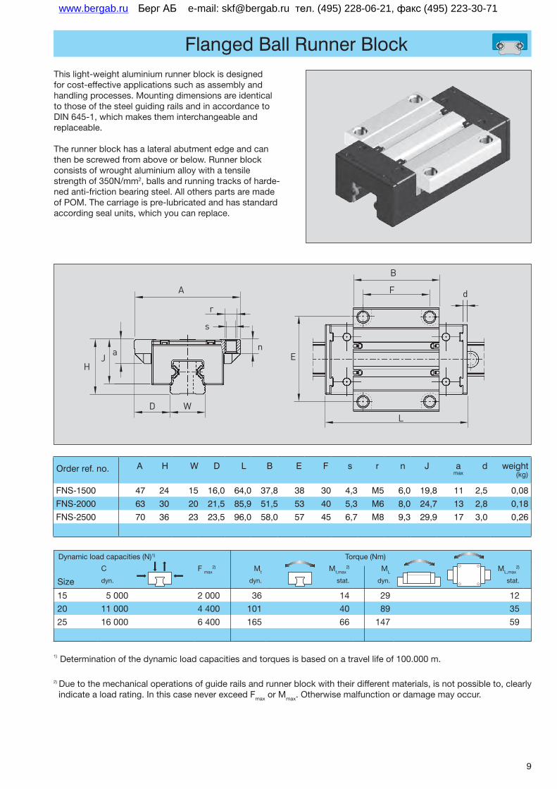
Flanged Ball Runner Block
Order ref. no. A H W D L B E F s r n J a max
d weight (kg)
FNS-1500 47 24 15 16,0 64,0 37,8 38 30 4,3 M5 6,0 19,8 11 2,5 0,08FNS-2000 63 30 20 21,5 85,9 51,5 53 40 5,3 M6 8,0 24,7 13 2,8 0,18FNS-2500 70 36 23 23,5 96,0 58,0 57 45 6,7 M8 9,3 29,9 17 3,0 0,26
This light-weight aluminium runner block is designed for cost-effective applications such as assembly and handling processes. Mounting dimensions are identical to those of the steel guiding rails and in accordance to DIN 645-1, which makes them interchangeable and replaceable.
The runner block has a lateral abutment edge and can then be screwed from above or below. Runner block consists of wrought aluminium alloy with a tensile strength of 350N/mm2, balls and running tracks of harde-ned anti-friction bearing steel. All others parts are made of POM. The carriage is pre-lubricated and has standard according seal units, which you can replace.
C F max2) Mt Mt,max
2) ML ML,max2)
Size dyn. dyn. stat. dyn. stat.
15 5 000 2 000 36 14 29 12
20 11 000 4 400 101 40 89 35
25 16 000 6 400 165 66 147 59
Dynamic load capacities (N)1) Torque (Nm)
A
r
D W
n
H
aJ
d
B
F
E
L
s
1) Determination of the dynamic load capacities and torques is based on a travel life of 100.000 m.
2) Due to the mechanical operations of guide rails and runner block with their different materials, is not possible to, clearly indicate a load rating. In this case never exceed Fmax or Mmax. Otherwise malfunction or damage may occur.
Берг АБ e-mail: [email protected] тел. (495) 228-06-21, факс (495) 223-30-71www.bergab.ru
10
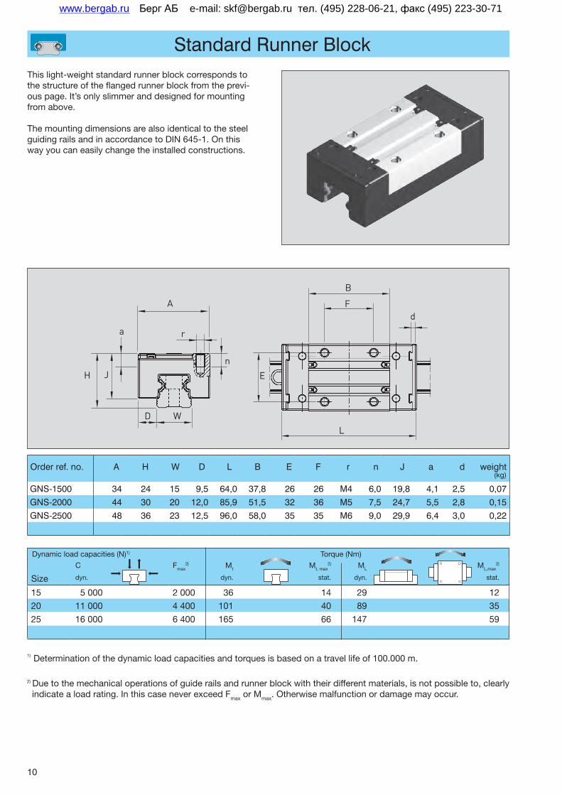
Standard Runner Block
Order ref. no. A H W D L B E F r n J a d weight (kg)
GNS-1500 34 24 15 9,5 64,0 37,8 26 26 M4 6,0 19,8 4,1 2,5 0,07GNS-2000 44 30 20 12,0 85,9 51,5 32 36 M5 7,5 24,7 5,5 2,8 0,15GNS-2500 48 36 23 12,5 96,0 58,0 35 35 M6 9,0 29,9 6,4 3,0 0,22
This light-weight standard runner block corresponds to the structure of the flanged runner block from the previ-ous page. It’s only slimmer and designed for mounting from above.
The mounting dimensions are also identical to the steel guiding rails and in accordance to DIN 645-1. On this way you can easily change the installed constructions.
A
r
n
a
H J
D W
B
E
F
L
C Fmax2) Mt Mt, max
2) ML ML,max2)
Size dyn. dyn. stat. dyn. stat.
15 5 000 2 000 36 14 29 12
20 11 000 4 400 101 40 89 35
25 16 000 6 400 165 66 147 59
Dynamic load capacities (N)1) Torque (Nm)
d
1) Determination of the dynamic load capacities and torques is based on a travel life of 100.000 m.
2) Due to the mechanical operations of guide rails and runner block with their different materials, is not possible to, clearly indicate a load rating. In this case never exceed Fmax or Mmax. Otherwise malfunction or damage may occur.
Берг АБ e-mail: [email protected] тел. (495) 228-06-21, факс (495) 223-30-71www.bergab.ru
11
Corrosion Resistant Profiled Rail
s r
G t
L
u
h v n
W
1) Pleaseorderseparately
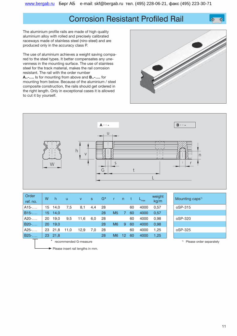
Thealuminiumprofilerailsaremadeofhighqualityaluminiumalloywithrolledandpreciselycalibratedracewaysmadeofstainlesssteel(niro-steel)andareproducedonlyintheaccuracyclassP.
Theuseofaluminiumachievesaweightsavingcompa-redtothesteeltypes.Itbettercompensatesanyune-vennessinthemountingsurface.Theuseofstainlesssteelforthetrackmaterial,makestherailcorrosionresistant.Therailwiththeordernumber A..-….IsformountingfromaboveandB..-….formountingfrombelow.Becauseofthealuminium/steelcompositeconstruction,therailsshouldgetorderedintherightlength.Onlyinexceptionalcasesitisallowedtocutitbyyourself.
A · · - B · · -
Pleaseinsertraillengthsinmm.
* recommendedG-measure
Order ref. no.
W h u v s G* r n t Lmax
weight kg/m
A15-. . . . 15 14,0 7,5 8,1 4,4 28 60 4000 0,57B15-. . . . 15 14,0 28 M5 7 60 4000 0,57A20-. . . . 20 19,0 9,5 11,6 6,0 28 60 4000 0,98B20-. . . . 20 19,0 28 M6 9 60 4000 0,98A25-. . . . 23 21,8 11,0 12,9 7,0 28 60 4000 1,25B25-. . . . 23 21,8 28 M6 12 60 4000 1,25
Mountingcaps1)
oSP-315
oSP-320
oSP-325
Берг АБ e-mail: [email protected] тел. (495) 228-06-21, факс (495) 223-30-71www.bergab.ru
12
Accessories
SealUnit
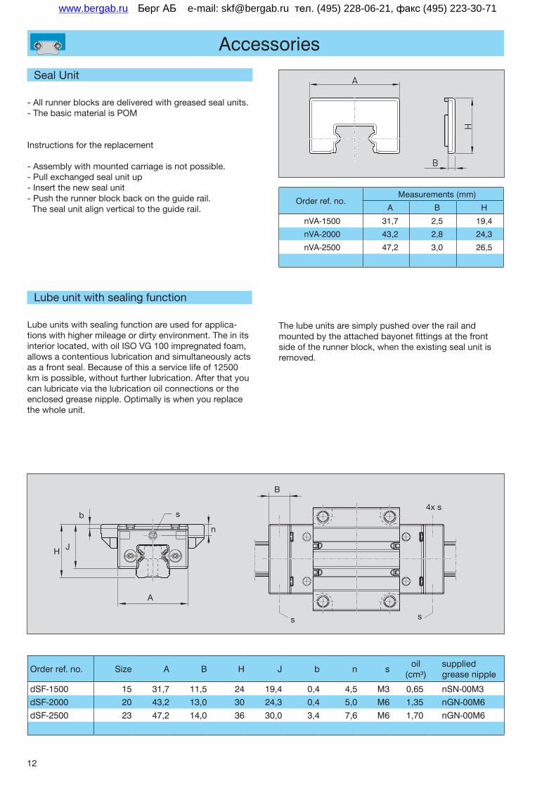
-Allrunnerblocksaredeliveredwithgreasedsealunits.-ThebasicmaterialisPOM
Instructionsforthereplacement
-Assemblywithmountedcarriageisnotpossible.-Pullexchangedsealunitup-Insertthenewsealunit-Pushtherunnerblockbackontheguiderail.Thesealunitalignverticaltotheguiderail.
Lubeunitwithsealingfunction
Lubeunitswithsealingfunctionareusedforapplica-tionswithhighermileageordirtyenvironment.Theinitsinteriorlocated,withoilISOVG100impregnatedfoam,allowsacontentiouslubricationandsimultaneouslyactsasafrontseal.Becauseofthisaservicelifeof12500kmispossible,withoutfurtherlubrication.Afterthatyoucanlubricateviathelubricationoilconnectionsortheenclosedgreasenipple.Optimallyiswhenyoureplacethewholeunit.
B
s s
4x s
A
J
b s
n
H
Order ref. no. Size A B H J b n soil
(cm³)supplied grease nipple
dSF-1500 15 31,7 11,5 24 19,4 0,4 4,5 M3 0,65 nSN-00M3dSF-2000 20 43,2 13,0 30 24,3 0,4 5,0 M6 1,35 nGN-00M6dSF-2500 23 47,2 14,0 36 30,0 3,4 7,6 M6 1,70 nGN-00M6
Order ref. no.Measurements (mm)
A B H
nVA-1500 31,7 2,5 19,4
nVA-2000 43,2 2,8 24,3
nVA-2500 47,2 3,0 26,5
Thelubeunitsaresimplypushedovertherailandmountedbytheattachedbayonetfittingsatthefrontsideoftherunnerblock,whentheexistingsealunitisremoved.
A
H
B
Берг АБ e-mail: [email protected] тел. (495) 228-06-21, факс (495) 223-30-71www.bergab.ru
13
Accessories
Lubricating nipple for lube units
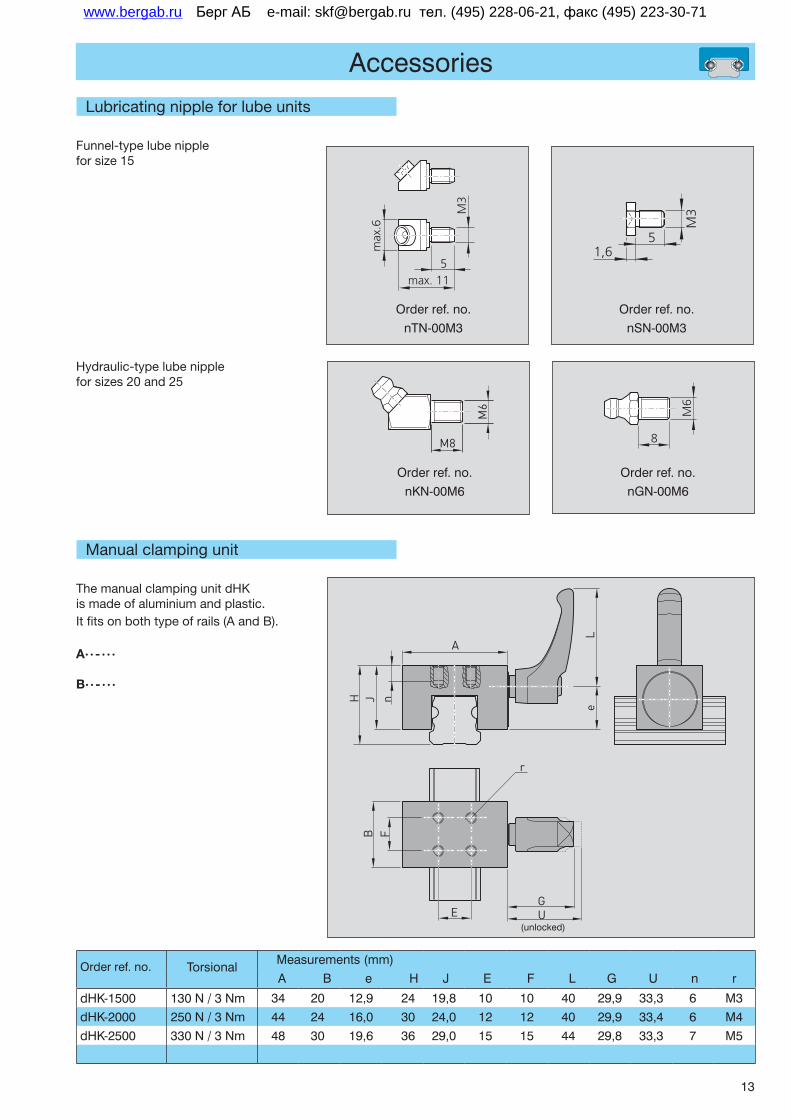
Funnel-type lube nipple for size 15
Hydraulic-type lube nipple for sizes 20 and 25
max. 115
max
.6
M3
5
M3
1,6
Order ref. no.nTN-00M3
Order ref. no.nSN-00M3
Order ref. no.nKN-00M6
Order ref. no.nGN-00M6
8
M6
Manual clamping unit
The manual clamping unit dHK is made of aluminium and plastic. It fits on both type of rails (A and B).
A· · - · · ·
B· · - · · ·
Order ref. no. Torsional Measurements (mm)A B e H J E F L G U n r
dHK-1500 130 N / 3 Nm 34 20 12,9 24 19,8 10 10 40 29,9 33,3 6 M3dHK-2000 250 N / 3 Nm 44 24 16,0 30 24,0 12 12 40 29,9 33,4 6 M4dHK-2500 330 N / 3 Nm 48 30 19,6 36 29,0 15 15 44 29,8 33,3 7 M5
A
M6
M8
r
GUE
nJHB F
Le
(unlocked)
Берг АБ e-mail: [email protected] тел. (495) 228-06-21, факс (495) 223-30-71www.bergab.ru

Берг АБ e-mail: [email protected] тел. (495) 228-06-21, факс (495) 223-30-71www.bergab.ru

Берг АБ e-mail: [email protected] тел. (495) 228-06-21, факс (495) 223-30-71www.bergab.ru
Stanze_SM102_TOP_V_2.0Linienstärke 0.1 mmHeidelberger DruckmaschinenM-BM DMP10/2001
Stanze_SM102_TOP_V_2.0Linienstärke 0.1 mmHeidelberger DruckmaschinenM-BM DMP10/2001
Stanze_SM102_TOP_V_1.0Linienstärke 0.1 mmHeidelberger DruckmaschinenM-BM DMP10/2001
1 2 3 4 5 6 7 8 9
Alulin
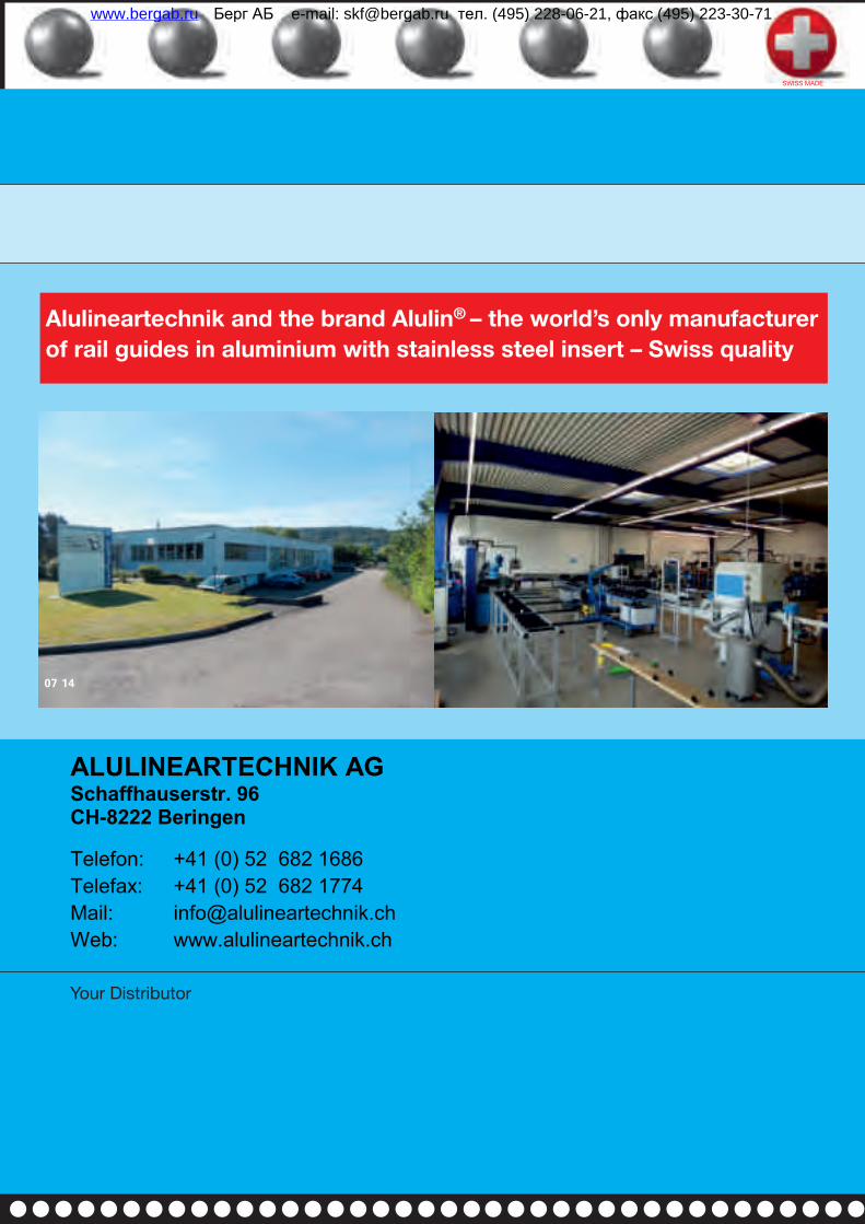
Alulineartechnik and the brand Alulin® – the world’s only manufacturer of rail guides in aluminium with stainless steel insert – Swiss quality
Your Distributor
SWISS MADE
L I G H T W E I G H T S T A I N L E S S I N T E R C H A N G E A B L E
07 14
Alulineartechnik AG
Alulin
ALUMINIUMRAIL GUIDES
SWISS MADE
L I G H T W E I G H T S T A I N L E S S I N T E R C H A N G E A B L E
Fal
zbo
gen
1
Fal
zbo
gen
1
Fal
zbo
gen
1
Fal
zbo
gen
1S
chö
n 0
01
- A
lulin
eart
ech
nik
EN
14-
0388
Dr.
Eri
ch T
rett
er G
mb
H C
o -
Alu
linea
rtec
hn
ik E
N
-
$[P
rod
uct
Nam
e]
- 0
9.07
.201
4 -
15
:39:
45
80% B C M Y CMY CMY B4 C4 M4 Y4 40% 80% B C M Y B C M Y 40% 80% B C M Y B C M Y 80% B C M Y B C M Y 40% 80% B C M Y
12345
5432
12345
5432
B C M Y 40% 80% B C M Y
12345
5432
12345
5432
B C M Y 40% 80% B4 C4 M4 Y4 MY CY CM B C M Y 40% 80% B C M Y CMY CMY B4 C4 M4 Y4 40% 80% B C M Y B C M Y 40% 80% B C M Y B C M Y 80% B C M Y B C M Y 40% 80% B C M Y
12345
5432
12345
5432
B C M Y 40% 80% B C M Y
12345
5432
12345
5432
B C M Y 40% 80% B4 C4 M4 Y4 MY CY CM B C M Y 40%
1 2 3 4 5 6 7 8 9 10 11 12 13 14 15 16 17 18 19 20 21 22 23 24 25 26 27 28 29 30 31 32
Prinect/FOGRA 4 Dipco 2.0 Format 102 © 2003 FOGRA/Heidelberger Druckmaschinen AG Prinect/FOGRA 4 Dipco 2.0 Format 102 © 2003 FOGRA/Heidelberger Druckmaschinen AG
C
M
Y
C
M
Y
C
M
Y
C
M
Y
1030x790_33Alulineartechnik EN 14-0388 Dr. Erich Tretter GmbH Co - Alulineartechnik EN - $[ProductName] - 09.07.2014 - 15:39:45
Schön - 001 - BlackSchön - 001 - CyanSchön - 001 - MagentaSchön - 001 - YellowDr. Tretter
Берг АБ e-mail: [email protected] тел. (495) 228-06-21, факс (495) 223-30-71www.bergab.ru