Embed Size (px)
Citation preview
ALUmInUm PIPewoRK - ALUmInUm PIPewoRK - ALUmInUm PIPewoRK - ALUmInUm PIPewoRK - ALUmInUm PIPewoRK - ALUmInUm PIPewoRK
FLUID PoweR DISTRIBUTIon SYSTemS - FLUID PoweR DISTRIBUTIon SYSTemS - FLUID PoweR DISTRIBUTIon SYSTemS - FLUID PoweR DISTRIBUTIon SYSTemS - FLUID PoweR DISTRIBUTIon SYSTemS
ALUmInUm PIPewoRK - ALUmInUm PIPewoRK - ALUmInUm PIPewoRK - ALUmInUm PIPewoRK - ALUmInUm PIPewoRK - ALUmInUm PIPewoRK 87
FLUID PoweR DISTRIBUTIon SYSTemS - FLUID PoweR DISTRIBUTIon SYSTemS - FLUID PoweR DISTRIBUTIon SYSTemS - FLUID PoweR DISTRIBUTIon SYSTemS - FLUID PoweR DISTRIBUTIon SYSTemS
HBS-AP ASSEMBLING INSTRUCTIONS
1. INTRODUCTION
1.1. Please read these instructions thoroughly before starting work, bearing in mind any pertinent regulations in force in your country, state or municipality.
1.2. Please pay close attention to any instructions identified by ATTENTION.
1.3. The HBS and AP series of products are suitable for the distribution of compressed air, vaccum and other non-ha-zardous gases.
1.4. For any application with water distribution, please check our sheet on page 86. For other fluids it is necessary to identify their exact composition and to check if they are compatible with the HBS and
AP systems; in case of any doubt, please contact the technical department of TeSeo or your local representative.
1.5. ATTENTION: TESEO is not responsible for problems resulting from the failure to follow the instructions contained in this manual.
3. PREPARATION
3.1. Cutting: this can be done by hand using a hacksaw provided that the blade has been lubricated with vaseline or other oils, as aluminum is a material which could clog the tool. when making many cuts, we suggest using a circular chop saw with metal-cut-ting blade.
3.2. Deburring: After cutting the pipe, it is necessary to deburr it using a deburring tool. This operation is re-quired to avoid damaging the o-Rings and to make for easier assembly. It is also important to deburr any holes that are drilled for the purpose of attaching an outlet plate. we recommend deburring to a maximum of 1mm around the hole in order to prevent damage to the o’Ring seal.
2. TOOLS AND FIXTURES
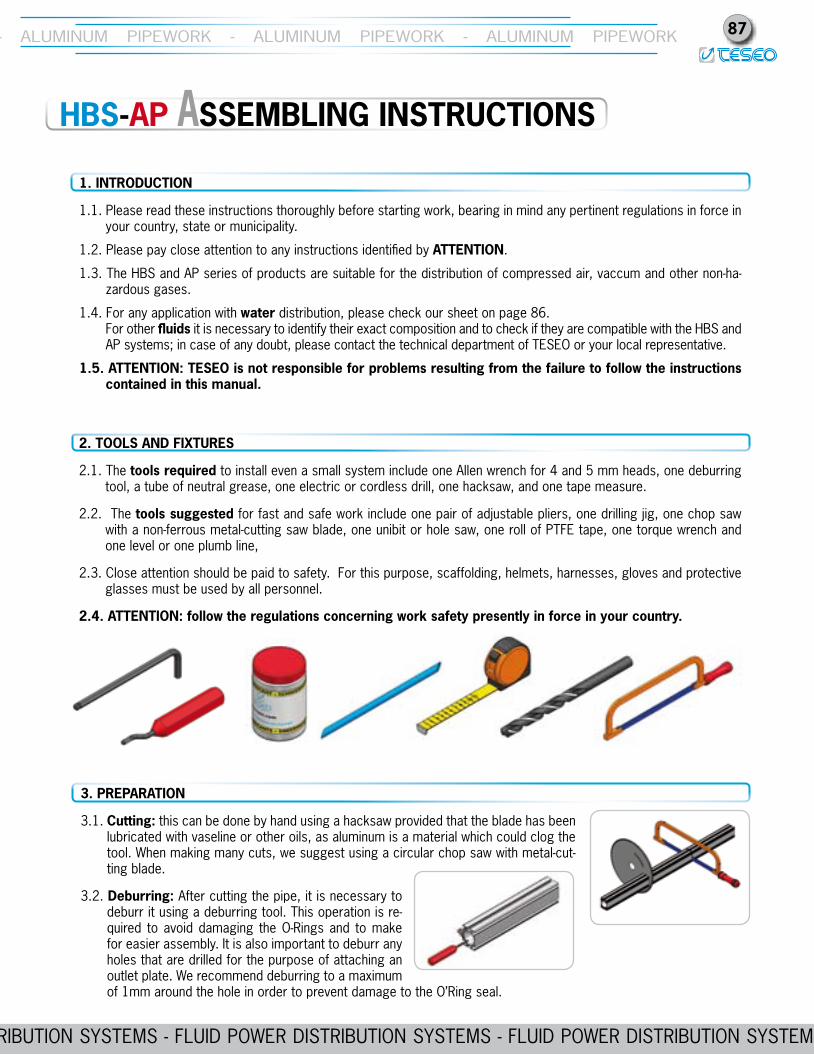
2.1. The tools required to install even a small system include one Allen wrench for 4 and 5 mm heads, one deburring tool, a tube of neutral grease, one electric or cordless drill, one hacksaw, and one tape measure.
2.2. The tools suggested for fast and safe work include one pair of adjustable pliers, one drilling jig, one chop saw with a non-ferrous metal-cutting saw blade, one unibit or hole saw, one roll of PTFe tape, one torque wrench and one level or one plumb line,
2.3. Close attention should be paid to safety. For this purpose, scaffolding, helmets, harnesses, gloves and protective glasses must be used by all personnel.
2.4. ATTENTION: follow the regulations concerning work safety presently in force in your country.
ALUmInUm PIPewoRK - ALUmInUm PIPewoRK - ALUmInUm PIPewoRK - ALUmInUm PIPewoRK - ALUmInUm PIPewoRK - ALUmInUm PIPewoRK88
FLUID PoweR DISTRIBUTIon SYSTemS - FLUID PoweR DISTRIBUTIon SYSTemS - FLUID PoweR DISTRIBUTIon SYSTemS - FLUID PoweR DISTRIBUTIon SYSTemS - FLUID PoweR DISTRIBUTIon SYSTemS
ALUmInUm PIPewoRK - ALUmInUm PIPewoRK - ALUmInUm PIPewoRK - ALUmInUm PIPewoRK - ALUmInUm PIPewoRK - ALUmInUm PIPewoRK
FLUID PoweR DISTRIBUTIon SYSTemS - FLUID PoweR DISTRIBUTIon SYSTemS - FLUID PoweR DISTRIBUTIon SYSTemS - FLUID PoweR DISTRIBUTIon SYSTemS - FLUID PoweR DISTRIBUTIon SYSTemS
3.3. Lubrication: in order to make it easier to insert joint, apply a small amount of grease to the inner surface of the hollow bar, in order to avoid any damage to the o’rings.
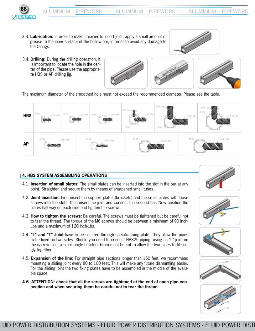
The maximum diameter of the smoothed hole must not exceed the recommended diameter. Please see the table.
HBS
AP
3.4. Drilling: During the drilling operation, it is important to locate the hole in the cen-ter of the pipe. Please use the appropria-te HBS or AP drilling jig.
4. HBS SYSTEM ASSEMBLING OPERATIONS
4.1. Insertion of small plates: The small plates can be inserted into the slot in the bar at any point. Straighten and secure them by means of sharpened small tubes.
4.2. Joint insertion: First insert the support plates (brackets) and the small plates with loose screws into the slots, then insert the joint and connect the second bar. now position the plates half-way on each side and tighten the screws.
4.3. How to tighten the screws: Be careful. The screws must be tightened but be careful not to tear the thread. The torque of the m6 screws should be between a minimum of 90 Inch-Lbs and a maximum of 120 Inch-Lbs.
4.4. “L” and “T” Joint have to be secured through specific fixing plate. They allow the pipes to be fixed on two sides. Should you need to connect HBS25 piping, using an “L” joint on the narrow side, a small angle notch of 6mm must be cut to allow the two pipes to fit snu-gly together.
4.5. Expansion of the line: For straight pipe sections longer than 150 feet, we recommend mounting a sliding joint every 80 to 100 feet. This will make any future dismantling easier. For the sliding joint the two fixing plates have to be assembled in the middle of the availa-ble space.
4.6. ATTENTION: check that all the screws are tightened at the end of each pipe con-nection and when securing them be careful not to tear the thread.
ALUmInUm PIPewoRK - ALUmInUm PIPewoRK - ALUmInUm PIPewoRK - ALUmInUm PIPewoRK - ALUmInUm PIPewoRK - ALUmInUm PIPewoRK
FLUID PoweR DISTRIBUTIon SYSTemS - FLUID PoweR DISTRIBUTIon SYSTemS - FLUID PoweR DISTRIBUTIon SYSTemS - FLUID PoweR DISTRIBUTIon SYSTemS - FLUID PoweR DISTRIBUTIon SYSTemS
ALUmInUm PIPewoRK - ALUmInUm PIPewoRK - ALUmInUm PIPewoRK - ALUmInUm PIPewoRK - ALUmInUm PIPewoRK - ALUmInUm PIPewoRK 89
FLUID PoweR DISTRIBUTIon SYSTemS - FLUID PoweR DISTRIBUTIon SYSTemS - FLUID PoweR DISTRIBUTIon SYSTemS - FLUID PoweR DISTRIBUTIon SYSTemS - FLUID PoweR DISTRIBUTIon SYSTemS
6.3. Isolation valves: For proper system design ball valves should be mounted both at the beginning of the line and at the beginning of the branches from the main line. mount a pressure gauge at the beginning of the main line and a sa-fety valve on the air receiver.
6.4. Take-offs for drop columns: To prevent all the impurities from fouling the bottom of the hollow bar, we suggest fitting the outlet plates on the sides of the hollow bar.
6.5. Flexible pipe: its use is recommended in order to isolate the installation from the vibrations of the compressor.
6.6. Grounding: it is recommended that any piping system be connected to ground in case of stray electrical currents.
6.7. ATTENTION: wear a safety helmet, harnesses and use scaffolding in compliance with all local, state and federal laws before tracing and installing the line, as these operations are usually carried out at a dan-gerous height.
5. AP SYSTEM ASSEMBLING OPERATIONS
5.1. Clamping brackets installation: insert one side of the clamping bracket in the groove of the profile, push both clamping brackets together until they make full contact with the pipe profile then tighten the screws securely.
5.2. Joints: introduce the joint into one pipe, then connect the second pipe, position the clamping bra-ckets so that half is grabbing one pipe and half the other and then tighten the screws securely.
5.3. Screws tightening: This is a very important operation. Screws must be tightened properly to avoid stripping the threads. The recommended tightening torque for m5 screws is between 90 inch-lbs and 120 inch-lbs maximum. For m6 screws the minimum is 110 inch-lbs and the maxi-mum 130 inch-lbs.
5.4. ATTENTION: once the assembly of every joint is completed, double check that the screws have been pro-perly secured and be sure that no threads are damaged due to excessive tightening.
6. INSTALLATION
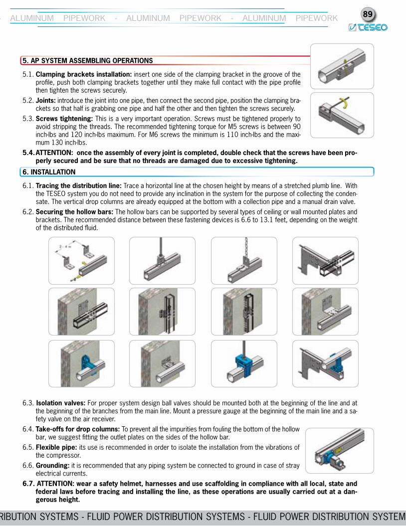
6.1. Tracing the distribution line: Trace a horizontal line at the chosen height by means of a stretched plumb line. with the TeSeo system you do not need to provide any inclination in the system for the purpose of collecting the conden-sate. The vertical drop columns are already equipped at the bottom with a collection pipe and a manual drain valve.
6.2. Securing the hollow bars: The hollow bars can be supported by several types of ceiling or wall mounted plates and brackets. The recommended distance between these fastening devices is 6.6 to 13.1 feet, depending on the weight of the distributed fluid.
ALUmInUm PIPewoRK - ALUmInUm PIPewoRK - ALUmInUm PIPewoRK - ALUmInUm PIPewoRK - ALUmInUm PIPewoRK - ALUmInUm PIPewoRK90
FLUID PoweR DISTRIBUTIon SYSTemS - FLUID PoweR DISTRIBUTIon SYSTemS - FLUID PoweR DISTRIBUTIon SYSTemS - FLUID PoweR DISTRIBUTIon SYSTemS - FLUID PoweR DISTRIBUTIon SYSTemS
ALUmInUm PIPewoRK - ALUmInUm PIPewoRK - ALUmInUm PIPewoRK - ALUmInUm PIPewoRK - ALUmInUm PIPewoRK - ALUmInUm PIPewoRK
FLUID PoweR DISTRIBUTIon SYSTemS - FLUID PoweR DISTRIBUTIon SYSTemS - FLUID PoweR DISTRIBUTIon SYSTemS - FLUID PoweR DISTRIBUTIon SYSTemS - FLUID PoweR DISTRIBUTIon SYSTemS
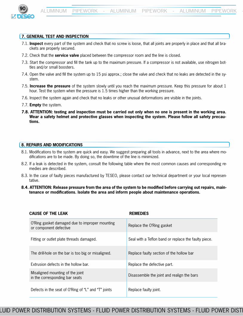
o’Ring gasket damaged due to improper mounting or component defective Replace the o’Ring gasket
Fitting or outlet plate threads damaged. Seal with a Teflon band or replace the faulty piece.
The drill-hole on the bar is too big or misaligned. Replace faulty section of the hollow bar
extrusion defects in the hollow bar. Replace the defective part.
misaligned mounting of the jointin the corresponding bar seats Disassemble the joint and realign the bars
Defects in the seat of o’Ring of “L” and “T” joints Replace faulty joint.
CAUSE OF THE LEAK REMEDIES
8. REPAIRS AND MODIFICATIONS
8.1. modifications to the system are quick and easy. we suggest preparing all tools in advance, next to the area where mo-difications are to be made. By doing so, the downtime of the line is minimized.
8.2. If a leak is detected in the system, consult the following table where the most common causes and corresponding re-medies are described.
8.3. In the case of faulty pieces manufactured by TeSeo, please contact our technical department or your local represen-tative.
8.4. ATTENTION: Release pressure from the area of the system to be modified before carrying out repairs, main-tenance or modifications. Isolate the area and inform people about maintenance operations.
7. GENERAL TEST AND INSPECTION
7.1. Inspect every part of the system and check that no screw is loose, that all joints are properly in place and that all bra-ckets are properly secured.
7.2. Check that the service valve placed between the compressor room and the line is closed.
7.3. Start the compressor and fill the tank up to the maximum pressure. If a compressor is not available, use nitrogen bot-tles and/or small boosters.
7.4. open the valve and fill the system up to 15 psi approx.; close the valve and check that no leaks are detected in the sy-stem.
7.5. Increase the pressure of the system slowly until you reach the maximum pressure. Keep this pressure for about 1 hour. Test the system when the pressure is 1.5 times higher than the working pressure.
7.6. Inspect the system again and check that no leaks or other unusual deformations are visible in the joints.
7.7. Empty the system.
7.8. ATTENTION: testing and inspection must be carried out only when no one is present in the working area. Wear a safety helmet and protective glasses when inspecting the system. Please follow all safety precau-tions.
ALUmInUm PIPewoRK - ALUmInUm PIPewoRK - ALUmInUm PIPewoRK - ALUmInUm PIPewoRK - ALUmInUm PIPewoRK - ALUmInUm PIPewoRK
FLUID PoweR DISTRIBUTIon SYSTemS - FLUID PoweR DISTRIBUTIon SYSTemS - FLUID PoweR DISTRIBUTIon SYSTemS - FLUID PoweR DISTRIBUTIon SYSTemS - FLUID PoweR DISTRIBUTIon SYSTemS
ALUmInUm PIPewoRK - ALUmInUm PIPewoRK - ALUmInUm PIPewoRK - ALUmInUm PIPewoRK - ALUmInUm PIPewoRK - ALUmInUm PIPewoRK 91
FLUID PoweR DISTRIBUTIon SYSTemS - FLUID PoweR DISTRIBUTIon SYSTemS - FLUID PoweR DISTRIBUTIon SYSTemS - FLUID PoweR DISTRIBUTIon SYSTemS - FLUID PoweR DISTRIBUTIon SYSTemS
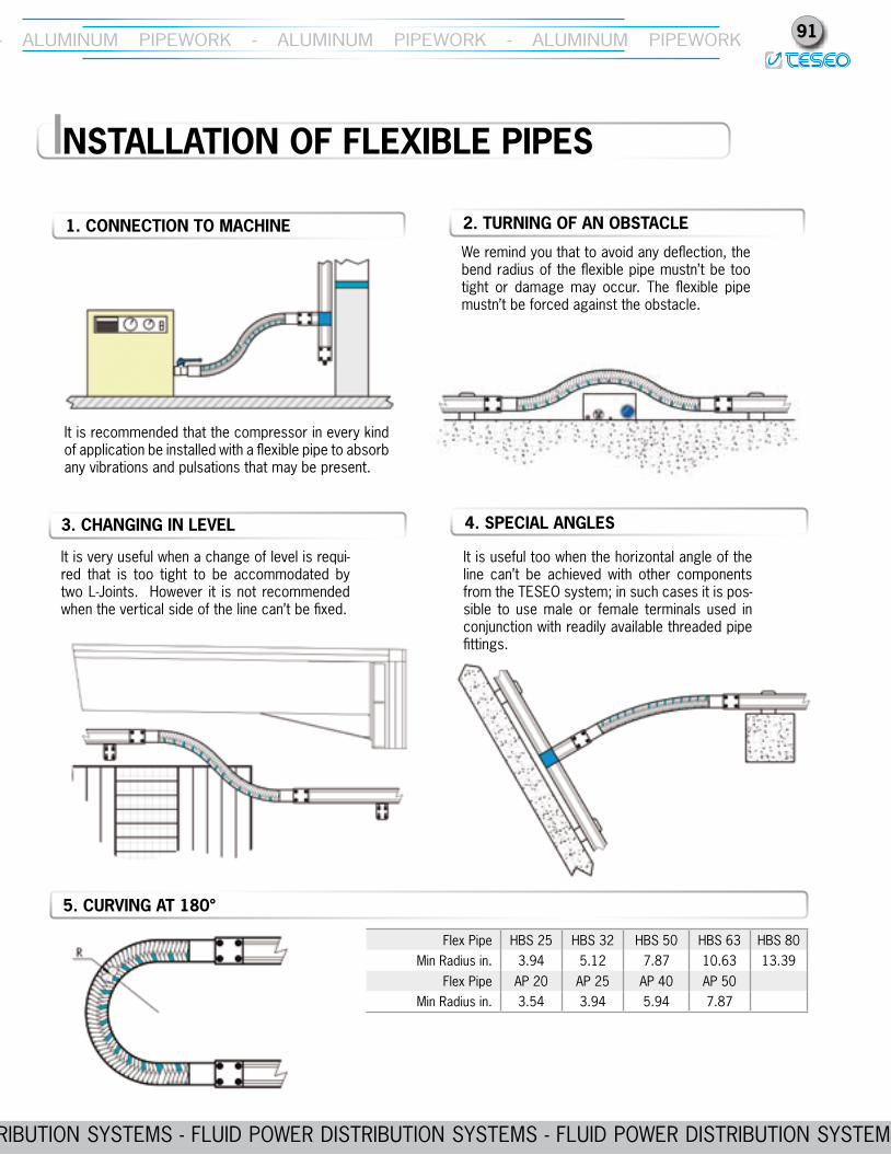
we remind you that to avoid any deflection, the bend radius of the flexible pipe mustn’t be too tight or damage may occur. The flexible pipe mustn’t be forced against the obstacle.
It is very useful when a change of level is requi-red that is too tight to be accommodated by two L-Joints. However it is not recommended when the vertical side of the line can’t be fixed.
2. TURNING OF AN OBSTACLE
5. CURVING AT 180°
INSTALLATION OF FLEXIBLE PIPES
It is recommended that the compressor in every kind of application be installed with a flexible pipe to absorb any vibrations and pulsations that may be present.
1. CONNECTION TO MACHINE
3. CHANGING IN LEVEL 4. SPECIAL ANGLES
Flex Pipe HBS 25 HBS 32 HBS 50 HBS 63 HBS 80min Radius in. 3.94 5.12 7.87 10.63 13.39
Flex Pipe AP 20 AP 25 AP 40 AP 50min Radius in. 3.54 3.94 5.94 7.87
It is useful too when the horizontal angle of the line can’t be achieved with other components from the TeSeo system; in such cases it is pos-sible to use male or female terminals used in conjunction with readily available threaded pipe fittings.


![[ ADGAS_Co Module_04 ] Pipework](https://img.pdfslide.net/doc/110x75/543fef1cb1af9f560a8b4ad0/-adgasco-module04-pipework.jpg)