Embed Size (px)
Citation preview

Aluminum Weld Discontinuities: Causes & Cures
Kyle Williams
1
February 04, 2016

2
Topics Definition of Terms
NDE Methods for Aluminum Welds
Cracks
Incomplete - Joint Penetration / Fusion
Porosity
Weld Inclusions
Weld Profiles
Procedure Qualification Problems
Summary
Topics

3
Terminology
Terminology
Discontinuity
An interruption of the typical structure of a material,
such as a lack of homogeneity in its mechanical,
metallurgical, or physical characteristics.
A discontinuity is not necessarily a defect.
Defect
A discontinuity that by nature or accumulated effect render a part or product unable to meet minimum applicable acceptance standards or specifications.
Ref: ANSI/AWS A3.0-10 – Standard Welding Terms and Definitions
4
Nondestructive Test Methods for Aluminum Welds
Common:
Visual (VT)
Penetrant (PT)
Radiographic (RT)
Ultrasonic (UT)
Specialized:
Eddy Current (ET)
Magnetic Particle (MT) cannot be used on aluminum.

5
Visual Inspection
Post-Weld Inspection
General appearance
Does it meet requirements
Pre-Weld Inspection:
Improper materials or condition
Joint fit-up
During Welding;
Verify requirements of weld procedure

6
Liquid Penetrant Inspection
Clean Develop Apply Penetrant Remove Penetrant
Used for detection of discontinuities that are open to surface
Two Common Methods:
Visible Dye
Fluorescent Dye

7
Radiographic Inspection
Used for detection of surface and internal discontinuities
Drawing from Welding Inspection Technology, Fourth Edition, American Welding Society.

K.L. Williams – Alcoa Technical Center 8
Ultrasonic Inspection
Used for detection of surface and internal discontinuities
Drawing from Welding Inspection Technology, Fourth Edition, American Welding Society.

9
Basic Discontinuity Causes
Improper metal preparation
− Joint preparation
− Cleaning
Incorrect filler selection
− Alloy or size
Incorrect welding equipment
Poor welding procedure or technique

10
Types of Discontinuities
Cracking
− Crater and weld
Incomplete penetration
Incomplete fusion
Porosity
Inclusions
− Tungsten, copper and ferrous

11
Inspection Methods
Visual Radiographic Ultrasonic Penetrant
Cracks X X X X
Incomplete Joint
PenetrationX X
Incomplete Fusion X X
Porosity X X X
Inclusions X X
x

12
Crater Cracks
Molten aluminum shrinks about 6%
in volume as it solidifies, 2x that of steel
Cracks will propagate in service

13
Crater Crack Prevention
“Button-Up” termination
− Start and stop the weld a couple times to add
filler to compensate for crater shrinkage
“Crater-Fill” termination
− Taper down current using a crater fill function in
the welding power supply or rapidly speed up
traverse
Stop on a run-out tab

14
Weld Cracking
Cold cracks
Cause:
− Insufficient weld strength under restraint
− Shallow root pass
Corrective means:
− Increase root pass throat
− Redesign to minimize restraint
− Change welding sequence to minimize restraint

15
Weld Cracking
Hot cracks
Cause:
− Tensile stress on partially solidified weld or base
metal
Incorrect filler alloy
Improper joint design
Excessive base alloy dilution
Low thermal gradient
16
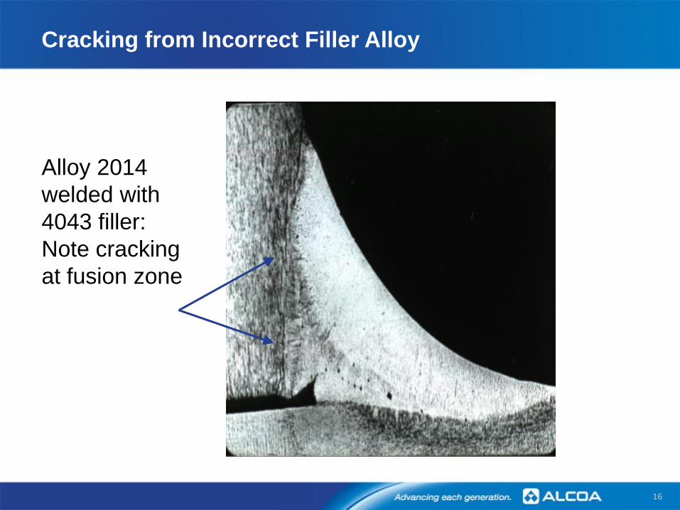
Cracking from Incorrect Filler Alloy
Alloy 2014
welded with
4043 filler:
Note cracking
at fusion zone

17
Cracking from Incorrect Filler Alloy
Tem
pe
ratu
re °
F
(Te
mpera
ture
°C
)
900
1000
1200 649
538
482
593
1180
950
1170
10651085
970
1010
2014 4043 2319
4145
(638)
(510)
(632)
(643)
(574)
(543)
(521)
(585)
1190
1100

Filler Alloy Selection Chart
18

19
Relative crack sensitivity vs. weld composition for various binary aluminum systems
0
0
0
0
0
0
1 2 3 4
Percent alloying addition of weld (%)
Rela
tive
cra
ck
se
nsit
ivit
y
5 6 7 8
Al-Li
(From Cross)
4043 Weld filler
2219
5083
6061
Al-Si
(From Singer
and Jennings)
Al-Mg
(From Dowd)
Al-Mg2Si
(From Jennings,
Singer and Pumphrey)
Al-Cu
(From Pumphrey
and Lyons)
0
0
0
0
0
0
1 2 3 4
Percent alloying addition of weld (%)
Rela
tive
cra
ck
se
nsit
ivit
y
5 6 7 8
Al-Li
(From Cross)
4043 Weld filler
2219
5083
6061
Al-Si
(From Singer
and Jennings)
Al-Mg
(From Dowd)
Al-Mg2Si
(From Jennings,
Singer and Pumphrey)
Al-Cu
(From Pumphrey
and Lyons)
Base Alloy Crack Sensitivity

20
Dilution Ratios of Weld Joints
60% filler metal
40% base metal
80% filler metal
20% base metal
20% filler metal
80% base metal
Fillet Welds
Single Vee-Groove Weld
Square Groove Weld

21
Weld Cracking
Hot cracks
Corrections:
− Proper joint design and filler
− Compressive joint loading
− Increased thermal gradient
Reduced interpass temperature
Chill bars
Increased travel speed
22
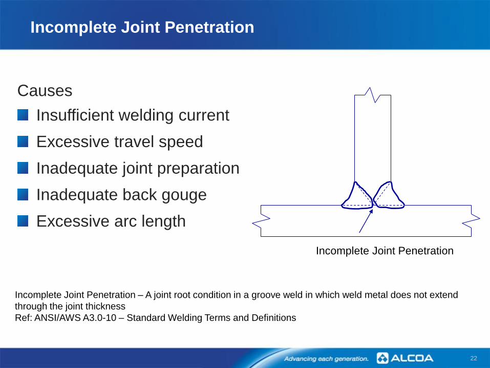
Incomplete Joint Penetration
Causes
Insufficient welding current
Excessive travel speed
Inadequate joint preparation
Inadequate back gouge
Excessive arc length
Incomplete Joint Penetration
Incomplete Joint Penetration – A joint root condition in a groove weld in which weld metal does not extend
through the joint thickness
Ref: ANSI/AWS A3.0-10 – Standard Welding Terms and Definitions

23
Groove Weld Root Penetration
Incomplete
Joint
Penetration

24
Incomplete Fusion
Causes
Inadequate oxide removal
Insufficient heat input
Narrow joint preparation
Improper torch angle
Excessive arc length
Excessive travel speed
Inadequate gas shielding
Improper welding equipment
Incomplete
Fusion
Incomplete Fusion – A weld discontinuity in which fusion did not occur between the weld metal
and the fusion faces or the adjoining weld beads
Ref: ANSI/AWS A3.0-10 – Standard Welding Terms and Definitions
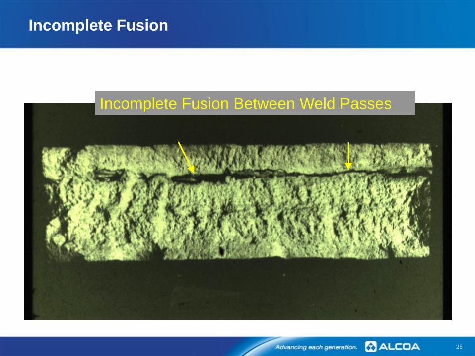
25
Incomplete Fusion Between Weld Passes
Incomplete Fusion
26
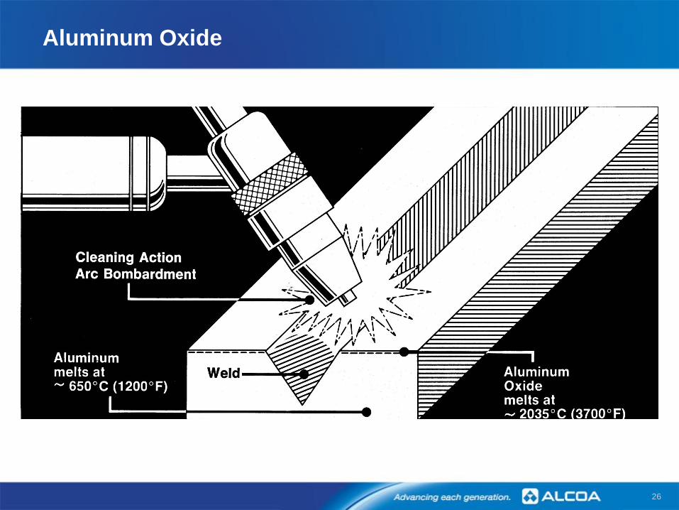
Aluminum Oxide

27
Root Side Oxide Displacement
Tight Integral or Removable
Backing Support Before Welding
Lack-of-fusion in Root of Weld
Due to Restricted Movement of
the Oxide
Satisfactory Weld with Adequate
Free Fall or Groove Depth in Backing Preferred
After
Before
Before
After
Preferred

28
GMA Welding Power Supply Characteristics
Ref: Figures 7.2 & 7.3 Welding Aluminum Theory and Practice, Fourth Edition,
The Aluminum Association, Washington, DC.

29
Weld Porosity
Basic cause – Hydrogen
Hydrogen sources:
− Hydrocarbons
− Moisture

30
Weld Porosity: Hydrogen Solubility
750 1100 1850
400 600 800 1000
Hy
dro
ge
n S
olu
bil
ity
(c
m 3/1
00
g)
Temperature ( o F )
Temperature ( oC )
1475
Solid
0.69
0.036
T melting (1220oF)
660oC
Liquid

31
Major Sources of Moisture or Hydrocarbons
Base Metal
Residual lubricant
Surface condensation
Water stain
Joint contaminants
Filler Metal
Residual lubricant
Hydrated oxide
Improper storage
Equipment
Water leaks
Contaminated tools
Improper grinding wheels
Shielding Gas
Moisture contamination
Turbulent shielding

32
Effect of Porosity on Mechanical Properties – 6061
Ref: Lawrence, F. V., Jr., and Munse, W. H., “Effects of Porosity on the Tensile Properties of 5083 and 6061 Aluminum Alloy
Weldments”, WRC Bull.181, February 1973.
33
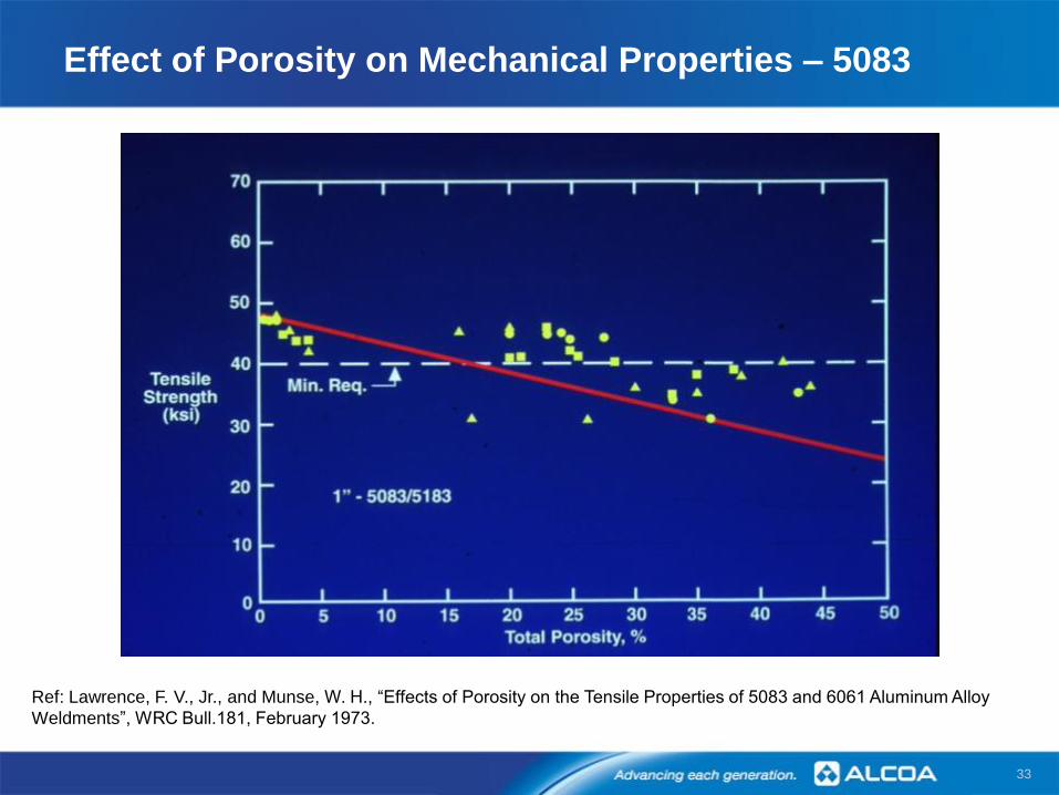
Effect of Porosity on Mechanical Properties – 5083
Ref: Lawrence, F. V., Jr., and Munse, W. H., “Effects of Porosity on the Tensile Properties of 5083 and 6061 Aluminum Alloy
Weldments”, WRC Bull.181, February 1973.

34
Weld Inclusions – Tungsten
Causes
Excessive current
− Size
− Tungsten type
Aluminum contamination
− Dip in weld
− Touch with filler
“Cold” starts
− Heat on tab
− Slope up current

35
Weld Inclusions – Tungsten
Does not alloy with aluminum
Treat as voids in weld
Radiograph of GTA Weld Showing Tungsten Inclusions

36
Weld Inclusions – Copper

37
Weld Inclusions – Copper
Causes
GMAW contact tube “burn-backs”
Improper GMA equipment set up
− Drive rolls, inlet/outlet guides, contact tip and liner
− Waves, kinks, snags in electrode
Copper backing – melting at open joint

38
Weld Inclusions – Ferrous
Causes
Wire brush bristles in joint
Steel backing or fixture
− Melting at open joint
− Rust flakes in joint

39
Weld Inclusions – Copper and Ferrous
Alloy with aluminum
Forms brittle interface
Surface corrosion hazard
Copper and ferrous inclusions are unacceptable to most
aluminum welding codes and standards and require
removal.

40
Undercut
Overlap
Weld Profiles
Undercut
Excessive welding currents
Improper welding technique
Overlap
Improper welding current /
technique
Oxide on surface of base
metal

K.L. Williams – Alcoa Technical Center 41
Weld Profiles
Convexity
Concavity
Convexity / Concavity
Reduced mechanical
properties and fatigue
strength
Improper arc length
Improper welding technique

42
Common Procedure Qualification Problems
Tensile tests
− Using too small of a test specimen
Guided bend testing
− Plunger type equipment used only
for soft or annealed tempers
− Wrap-around best for all aluminum alloys
− Improper bend radius or specimen thickness

43
Guided Bend – Plunger

44
Guided Bend – Wraparound
45
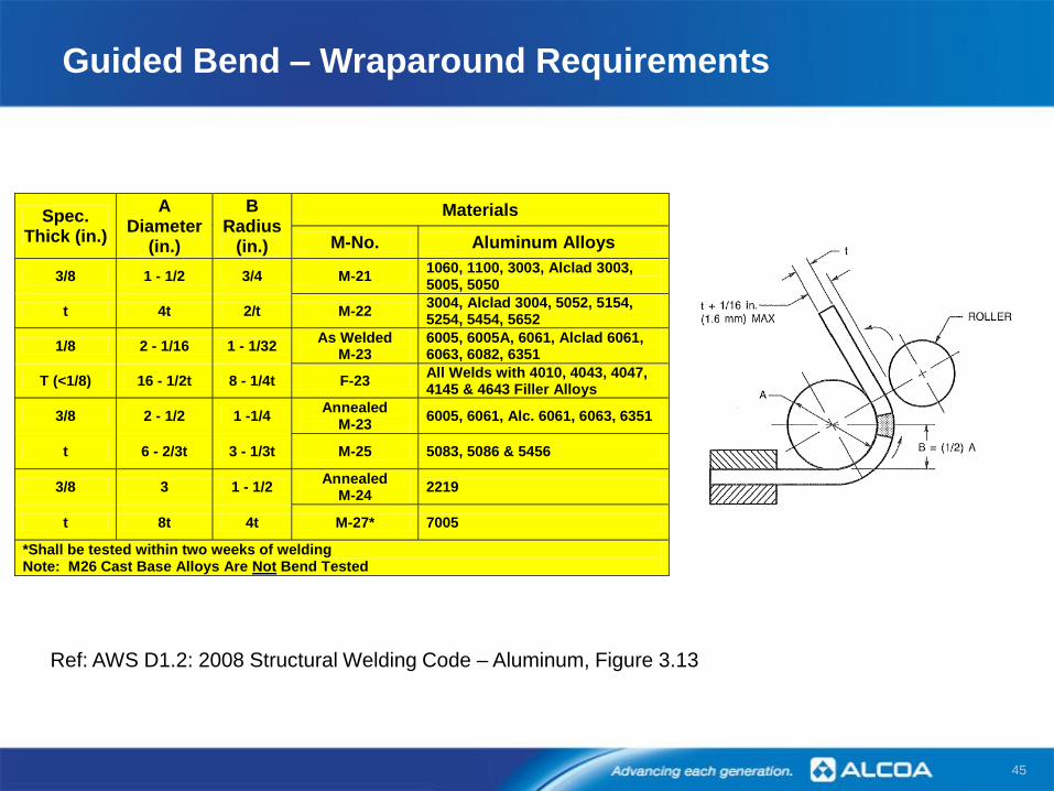
Guided Bend – Wraparound Requirements
Spec. Thick (in.)
A Diameter
(in.)
B Radius
(in.)
Materials
M-No. Aluminum Alloys
3/8 1 - 1/2 3/4 M-21 1060, 1100, 3003, Alclad 3003, 5005, 5050
t 4t 2/t M-22 3004, Alclad 3004, 5052, 5154, 5254, 5454, 5652
1/8 2 - 1/16 1 - 1/32 As Welded
M-23 6005, 6005A, 6061, Alclad 6061, 6063, 6082, 6351
T (<1/8) 16 - 1/2t 8 - 1/4t F-23 All Welds with 4010, 4043, 4047, 4145 & 4643 Filler Alloys
3/8 2 - 1/2 1 -1/4 Annealed
M-23 6005, 6061, Alc. 6061, 6063, 6351
t 6 - 2/3t 3 - 1/3t M-25 5083, 5086 & 5456
3/8 3 1 - 1/2 Annealed
M-24 2219
t 8t 4t M-27* 7005
*Shall be tested within two weeks of welding Note: M26 Cast Base Alloys Are Not Bend Tested
Ref: AWS D1.2: 2008 Structural Welding Code – Aluminum, Figure 3.13

46
Summary
Quality aluminum weldments can be made by:
Use of proper welding procedures
Use of proper welding equipment
Reasonable production control of material cleanliness
and joint fit-up
The best quality control is a properly trained conscientious
welder.

47


![A Practical Approach to Modeling Aluminum Weld Fracture ... · A Practical Approach to Modeling Aluminum Weld Fracture for Structural Applications ... (Mazzolani [13])](https://img.pdfslide.net/doc/110x75/5c6a53c009d3f27a7e8c80ba/a-practical-approach-to-modeling-aluminum-weld-fracture-a-practical-approach.jpg)