Embed Size (px)
Citation preview
Annual Meeting March 21-23, 2004 Marriott Rivercenter Hotel San Antonio, TX
AM-04-35 Packed FCCU Main Fractionator Upgrades for
Performance and Reliability
Presented By: Dana Laird Principal Process Engineer Koch-Glitsch LP St. Paul, MN
National Petrochemical & Refiners Association 1899 L Street, NW Suite 1000 Washington, DC 20036.3896
202.457.0480 voice 202.429.7726 fax www.npra.org

This paper has been reproduced for the author or authors as a courtesy by the National Petrochemical & Refiners Association. Publication of this paper does not signify that the contents necessarily reflect the opinions of the NPRA, its officers, directors, members, or staff. Requests for authorization to quote or use the contents should be addressed directly to the author(s)

Introduction FCCU Main Fractionators are typically one of the major FCC unit bottlenecks. In addition, Fractionator pressure drop can contribute to main air blower or wet gas compressor constraints. During the last 25 years refiners have revamped the Fractionator with high capacity trays or structured packing to increase capacity, reduce pressure drop, or both. Structured packing has been applied in approximately 100 Main Fractionators. These revamps have resulted in significant capacity gains1. Many of these towers have been in service for several years with no additional modifications despite the fact that unit charge rate and/or severity has increased. These changes significantly alter the internal loads on the tower. Trays, packing, and distributors may now be operating outside of their design range, causing loss in capacity, efficiency, or both.
Since the first FCCU Main Fractionator was packed there have been significant technology improvements in both process performance and reliability. New packing and distributor designs offer greater capacity or improved efficiency. Reliability improvements have also been made. Some of these improvements are due to the way a given technology is applied in the FCCU, while others are technology developments. Main Fractionators that were revamped more than a few years ago can often achieve improvements in capacity or reliability through implementation of these enhancements.
New clean fuels regulations also potentially impact the operation of the FCCU Main Fractionator. Whether the refiner is considering splitting FCC Naphtha, undercutting LCO or Naphtha, or cat feed hydrotreating the Main Fractionator loads will probably change. Existing equipment may not perform well under the new loads. Undercutting FCC Naphtha in the Main Fractionator also increases the potential for salt deposition in the top of the tower due to the lower overhead temperature. Proper design and operating procedures can deal with salt deposition. However, if it is not considered unit reliability and performance will be compromised.
Years of operation in the severe environment presented by the FCCU Main Fractionator can cause failure or damage to tower internals even if originally designed with this severity in mind. Experience gained from many applications has resulted in improved reliability through better design practices and more thorough understanding of the application. Older packed Main Fractionators can often benefit from a review of the installation with these new developments in mind.
A thorough review of the existing unit along with operating history and projected heat and material balances will identify problems with existing equipment and provide alternatives to eliminate the problem. It will also identify potential capacity, efficiency, or reliability improvements. Some important review considerations are outlined below.
Discussion
There are many things to consider when evaluating a potential FCCU Main Fractionator revamp. If the unit has been revamped previously and is now being pushed closer to the ultimate limit these considerations are even more critical. Improper design can severely undermine project economics.
Separation Efficiency vs. Capacity
In general, when revamping from conventional trays to high capacity trays there will be no loss in fractionation capability. When revamping from trays to structured packing separation efficiency sometimes must be sacrificed, depending on column configuration.
AM-04-35
Page 1
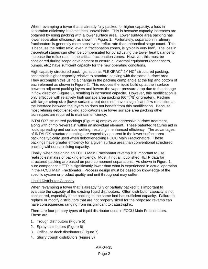
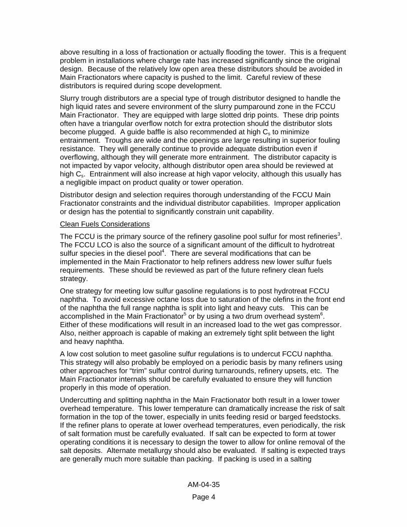
When revamping a tower that is already fully packed for higher capacity, a loss in separation efficiency is sometimes unavoidable. This is because capacity increases are obtained by using packing with a lower surface area. Lower surface area packing has lower separation efficiency, as shown in Figure 1. Fortunately, separation in refinery fractionators is generally more sensitive to reflux rate than theoretical stage count. This is because the reflux ratio, even in fractionation zones, is typically very low2. The loss in theoretical stages can often be compensated for by adjusting the tower heat balance to increase the reflux ratio in the critical fractionation zones. However, this must be considered during scope development to ensure all external equipment (condensers, pumps, etc.) have sufficient capacity for the new operating conditions.
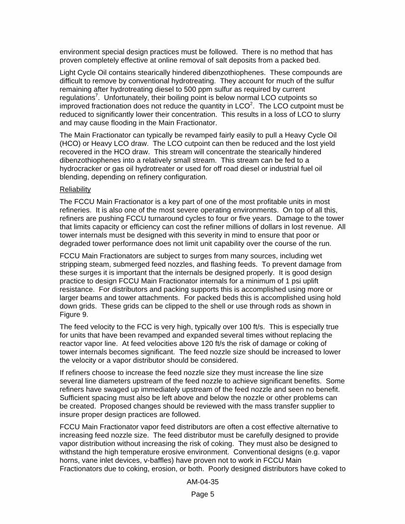
High capacity structured packings, such as FLEXIPAC® 2Y HC® structured packing, accomplish higher capacity relative to standard packing with the same surface area. They accomplish this using a change in the packing crimp angle at the top and bottom of each element as shown in Figure 2. This reduces the liquid build up at the interface between adjacent packing layers and lowers the vapor pressure drop due to the change in flow direction ( ), resulting in increased capacity. However, this modification is only effective with relatively high surface area packing (60 ft2/ft3 or greater). Packing with larger crimp size (lower surface area) does not have a significant flow restriction at the interface between the layers so does not benefit from this modification. Because most refining debottlenecking applications use lower surface area packing other techniques are required to maintain efficiency.
Figure 3
INTALOX® structured packings ( ) employ an aggressive surface treatment, along with crimp “reversals” within an individual element. These patented features aid in liquid spreading and surface wetting, resulting in enhanced efficiency. The advantages of INTALOX structured packing are especially apparent in the lower surface area packings typically used when debottlenecking FCCU Main Fractionators. These packings have greater efficiency for a given surface area than conventional structured packing without sacrificing capacity.
Figure 4
Finally, when designing an FCCU Main Fractionator revamp it is important to use realistic estimates of packing efficiency. Most, if not all, published HETP data for structured packing are based on pure component separations. As shown in , pure component HETP is significantly lower than what is experienced in actual operation in the FCCU Main Fractionator. Process design must be based on knowledge of the specific system or product quality and unit throughput may suffer.
Figure 1
Liquid Distributor Capacity
When revamping a tower that is already fully or partially packed it is important to evaluate the capacity of the existing liquid distributors. Often distributor capacity is not considered, especially if the packing in the same bed has sufficient capacity. Failure to replace or modify distributors that are not properly sized for the proposed revamp can have consequences ranging from insignificant to catastrophic.
There are four primary types of liquid distributor used in FCCU Main Fractionators. These are:
1. Trough distributors ( ) Figure 52. Spray distributors ( ) Figure 63. Orifice, or deck distributors ( ) Figure 74. Slurry trough distributors (Figure 8)
AM-04-35
Page 2

These distributors have varying degrees of tolerance for operating outside design ranges. None of these distributor types provide good distribution at turndown below their lower operating point. Some can tolerate overflowing liquid with minimal consequences depending on the application. High vapor rates can cause others to malfunction even if the liquid flow rate is within the design range.
High efficiency trough distributors have a series of troughs with raised drip orifices in the side walls. The liquid is directed from the orifice to the packing by a drip tube or baffle. Liquid is fed to the troughs from one or more parting boxes. They will continue to provide satisfactory distribution for some beds in the FCCU Main Fractionator even when overflowing. However, product quality may suffer if the distributors above naphtha/LCO or light/heavy naphtha fractionation beds are allowed to overflow. Entrainment will also increase from an overflowing distributor. If the bed above is not near flood the increased entrainment may have a minor or insignificant impact. High vapor velocity does not impact distributor capacity but may entrain liquid from the distributor, adversely impacting distribution quality. At extremely high Cs (Equation 1) it may be necessary to utilize special distributor design features to prevent entrainment. Distributor open area should also be reviewed at high Cs. gives some rules of thumb for tower capacity relative to Cs.
Table 1
Equation 1
vl
vs vC
ρρρ−
=
where
=v Superficial Vapor Velocity, ft/s
=vρ Vapor Density, lb/ft3
=lρ Liquid Density, lb/ft3
Spray distributors consist of a header and laterals with several full cone spray nozzles. They are typically used above pumparounds in FCCU Main Fractionators. When operated above their design rate these distributors will have a very high pressure drop and generate small droplets. These distributors will increase the entrainment load to the bed above, especially at high tower Cs. High vapor velocity does not impact distributor capacity but will increase the entraiment. These distributors should not be used on flashing feeds so are not appropriate for pumparounds containing rich sponge oil returning to the Main Fractionator. They should also be avoided in the slurry pumparound due to the potential for erosion of the nozzles.
Orifice distributors consist of a tray with vapor risers and drip orifices in the tray deck. They are sometimes equipped with tubes that elevate the drip orifice above the tray deck for fouling resistance. They are capable of providing adequate liquid distribution to pumparounds and less critical fractionation zones. They can function as a combination collector-distributor, reducing the required tower height in some installations. Because they have less open area than other designs severe entrainment can occur when the distributor overflows. In addition, the liquid height on the distributor is a function of both the liquid pressure drop through the orifice and the vapor pressure drop through the risers. Increased vapor traffic may cause the distributor to flood even if the liquid rate is within the design range. When this happens, liquid will back up into the trays or packing
AM-04-35
Page 3
above resulting in a loss of fractionation or actually flooding the tower. This is a frequent problem in installations where charge rate has increased significantly since the original design. Because of the relatively low open area these distributors should be avoided in Main Fractionators where capacity is pushed to the limit. Careful review of these distributors is required during scope development.
Slurry trough distributors are a special type of trough distributor designed to handle the high liquid rates and severe environment of the slurry pumparound zone in the FCCU Main Fractionator. They are equipped with large slotted drip points. These drip points often have a triangular overflow notch for extra protection should the distributor slots become plugged. A guide baffle is also recommended at high Cs to minimize entrainment. Troughs are wide and the openings are large resulting in superior fouling resistance. They will generally continue to provide adequate distribution even if overflowing, although they will generate more entrainment. The distributor capacity is not impacted by vapor velocity, although distributor open area should be reviewed at high Cs. Entrainment will also increase at high vapor velocity, although this usually has a negligible impact on product quality or tower operation.
Distributor design and selection requires thorough understanding of the FCCU Main Fractionator constraints and the individual distributor capabilities. Improper application or design has the potential to significantly constrain unit capability.
Clean Fuels Considerations
The FCCU is the primary source of the refinery gasoline pool sulfur for most refineries3. The FCCU LCO is also the source of a significant amount of the difficult to hydrotreat sulfur species in the diesel pool4. There are several modifications that can be implemented in the Main Fractionator to help refiners address new lower sulfur fuels requirements. These should be reviewed as part of the future refinery clean fuels strategy.
One strategy for meeting low sulfur gasoline regulations is to post hydrotreat FCCU naphtha. To avoid excessive octane loss due to saturation of the olefins in the front end of the naphtha the full range naphtha is split into light and heavy cuts. This can be accomplished in the Main Fractionator5 or by using a two drum overhead system6. Either of these modifications will result in an increased load to the wet gas compressor. Also, neither approach is capable of making an extremely tight split between the light and heavy naphtha.
A low cost solution to meet gasoline sulfur regulations is to undercut FCCU naphtha. This strategy will also probably be employed on a periodic basis by many refiners using other approaches for “trim” sulfur control during turnarounds, refinery upsets, etc. The Main Fractionator internals should be carefully evaluated to ensure they will function properly in this mode of operation.
Undercutting and splitting naphtha in the Main Fractionator both result in a lower tower overhead temperature. This lower temperature can dramatically increase the risk of salt formation in the top of the tower, especially in units feeding resid or barged feedstocks. If the refiner plans to operate at lower overhead temperatures, even periodically, the risk of salt formation must be carefully evaluated. If salt can be expected to form at tower operating conditions it is necessary to design the tower to allow for online removal of the salt deposits. Alternate metallurgy should also be evaluated. If salting is expected trays are generally much more suitable than packing. If packing is used in a salting
AM-04-35
Page 4
environment special design practices must be followed. There is no method that has proven completely effective at online removal of salt deposits from a packed bed.
Light Cycle Oil contains stearically hindered dibenzothiophenes. These compounds are difficult to remove by conventional hydrotreating. They account for much of the sulfur remaining after hydrotreating diesel to 500 ppm sulfur as required by current regulations7. Unfortunately, their boiling point is below normal LCO cutpoints so improved fractionation does not reduce the quantity in LCO2. The LCO cutpoint must be reduced to significantly lower their concentration. This results in a loss of LCO to slurry and may cause flooding in the Main Fractionator.
The Main Fractionator can typically be revamped fairly easily to pull a Heavy Cycle Oil (HCO) or Heavy LCO draw. The LCO cutpoint can then be reduced and the lost yield recovered in the HCO draw. This stream will concentrate the stearically hindered dibenzothiophenes into a relatively small stream. This stream can be fed to a hydrocracker or gas oil hydrotreater or used for off road diesel or industrial fuel oil blending, depending on refinery configuration.
Reliability
The FCCU Main Fractionator is a key part of one of the most profitable units in most refineries. It is also one of the most severe operating environments. On top of all this, refiners are pushing FCCU turnaround cycles to four or five years. Damage to the tower that limits capacity or efficiency can cost the refiner millions of dollars in lost revenue. All tower internals must be designed with this severity in mind to ensure that poor or degraded tower performance does not limit unit capability over the course of the run.
FCCU Main Fractionators are subject to surges from many sources, including wet stripping steam, submerged feed nozzles, and flashing feeds. To prevent damage from these surges it is important that the internals be designed properly. It is good design practice to design FCCU Main Fractionator internals for a minimum of 1 psi uplift resistance. For distributors and packing supports this is accomplished using more or larger beams and tower attachments. For packed beds this is accomplished using hold down grids. These grids can be clipped to the shell or use through rods as shown in
. Figure 9
The feed velocity to the FCC is very high, typically over 100 ft/s. This is especially true for units that have been revamped and expanded several times without replacing the reactor vapor line. At feed velocities above 120 ft/s the risk of damage or coking of tower internals becomes significant. The feed nozzle size should be increased to lower the velocity or a vapor distributor should be considered.
If refiners choose to increase the feed nozzle size they must increase the line size several line diameters upstream of the feed nozzle to achieve significant benefits. Some refiners have swaged up immediately upstream of the feed nozzle and seen no benefit. Sufficient spacing must also be left above and below the nozzle or other problems can be created. Proposed changes should be reviewed with the mass transfer supplier to insure proper design practices are followed.
FCCU Main Fractionator vapor feed distributors are often a cost effective alternative to increasing feed nozzle size. The feed distributor must be carefully designed to provide vapor distribution without increasing the risk of coking. They must also be designed to withstand the high temperature erosive environment. Conventional designs (e.g. vapor horns, vane inlet devices, v-baffles) have proven not to work in FCCU Main Fractionators due to coking, erosion, or both. Poorly designed distributors have coked to
AM-04-35
Page 5

the point that vapor flow was obstructed, resulting in premature shutdowns. A properly designed distributor provides more uniform flow entering the slurry pumparound bed.
and compare the vapor distribution with and without the proprietary Koch-Glitsch Model 798 Vapor Distributor using Computational Fluid Dynamics (CFD) analysis. This high open area distributor improves distribution significantly but resists damage and coking.
Figure 10 Figure 11
Although not as prevalent as in crude and coker units, salt deposition can be a problem in the top of FCCU Main Fractionators. Certain feedstocks, such as unhydrotreated resid, are much more prone to produce salts than others. Also, towers that have a heavy naphtha side draw, or refiners that undercut the naphtha endpoint, are more likely to form salt deposits. As discussed above, if salt deposition is expected it must be designed for. Provisions for on-line water washing should be included in the design and structured packing should be avoided.
The slurry pumparound zone presents a special reliability challenge. The reactor vapor entering the zone is superheated to approximately 1000°F and contains FCCU catalyst fines. Condensed slurry is cooled and re-circulated to the top of the bed to cool the vapor before it enters the upper section of the tower. The circulating slurry stream contains catalyst fines as well as coke particles that are formed in the bottom of the tower and the heat exchanger circuit.
The internals in this section must be able to transfer the required heat duty as well as resist fouling and upset. As discussed above, special distributors ( ) have been developed which resist fouling while maintaining good liquid distribution. Traditional installations have used shed or disc and donut trays to provide vapor-liquid contacting. However, as refiners push their Main Fractionators these trays often do not have the capacity or efficiency to obtain the desired rate. FLEXIGRID® Style 2 grid packing (Figure 12) has proven to provide as good or better reliability than shed trays in the slurry pumparound section with significant increase in capacity. Slurry pumparounds with FLEXIGRID packing are in operation at Cs over 0.5 ft/s. Figure 13 shows FLEXIGRID packing that has been removed for inspection after 12 years in slurry pumparound service without being removed. The grid was re-installed without cleaning.
Figure 8
Case Study - FCC Conversion Increase
An independent refiner planned a revamp to increase conversion in their FCCU. This increase had to be accomplished without sacrificing unit charge rate or product quality. The Main Fractionator was a unit bottleneck but had already been revamped to increase capacity several times. The LCO and HCO pumparounds were packed first, followed by the slurry and top pumparounds and the fractionation zones at the next turnaround. Finally, the wash zone was packed, resulting in a fully packed tower. In addition, as shown in Figure 14, this tower is already one of the most heavily loaded FCCU Main Fractionators in the refining industry.
A thorough test run was conducted to define base case unit operation. The test run data were used to develop a simulation of the tower, which allowed evaluation of the existing internals (shown in Figure 15). The evaluation showed that, although the entire tower was very close to flood (in some cases over 90% of calculated flood point) the only component flooded at the base case conditions was the orifice type LCO pumparound distributor. Gamma scans confirmed this distributor was flooded, with liquid backing up 4-6 feet into the naphtha/LCO fractionation bed.
AM-04-35
Page 6
A pressure survey conducted as part of the test run showed damage to the naphtha pumparound/reflux spray distributor at the top of the tower. This damage explained poor distribution indicated by the gamma scan.
In addition to a detailed test run including field pressure surveys, revamp scope development should include a detailed review of prior turnaround inspection records. This review should evaluate areas of recurring damage to the Main Fractionator and identify the root cause. In this case, two areas of primary concern were identified:
1) Minor damage was noted to the bottom of the slurry pumparound bed in each of the two previous turnarounds. At each turnaround, the damaged area was reinforced without removing the bed. This bed consists of approximately 11 feet of FLEXIGRID 2 supported directly on a support ring and beams and has been in service for 12 years. Newer designs use a bolted support grid below the FLEXIGRID packing that is more reliable. However, despite the damage, the bed had provided trouble free operation for the entire 12 year life with only minor maintenance during the two previous turnarounds.
In addition to the support design, feed velocity was identified as a potential root cause for the damage. The feed enters the column at over 180 ft/s with no feed distributor. The areas of damage correspond roughly to the areas of high velocity shown in Figure 10. High velocity vapor, possibly with entrained liquid, was literally ripping the bed apart from the bottom.
2) The LCO pumparound return, containing the rich sponge oil returning from the gas plant, returns into a false downcomer above the orifice plate distributor. This false downcomer was repeatedly found blown apart and lying on the distributor. The downcomer was not constructed to withstand the force caused by the vaporization as the rich sponge oil was flashed to main column pressure.
The base case simulation was adjusted using projected post-turnaround yields. Since the Main Fractionator pumparounds are heat integrated with the FCCU Gas plant the modified simulation was constrained to meet the required gas plant heat loads. Other constraints, including overhead condenser, wet gas compressor, and operating pressure were maintained. The Main Fractionator internals were reevaluated using this simulation.
Upon evaluation of the existing internals with the revamp simulation, two distributors were identified, in addition to the LCO pumparound distributor already noted, that required replacement for the new operating conditions. In addition, the HCO pumparound packing would be expected to flood. However, the greatest concern was the naphtha/LCO fractionation bed. This bed consisted of approximately 21.5’ of FLEXIPAC 3Y structured packing (34 ft2/ft3). The maximum load in this bed was projected to be at 100% rated flood with a Cs of 0.53 ft/s after the revamp. This is the critical fractionation bed in the tower and cannot tolerate the loss in fractionation efficiency associated with changing to a higher capacity packing.
INTALOX structured packings have been shown to have slightly greater efficiency than other structured packing of similar surface area. As noted earlier, this is especially true for the lower surface area structured packings. In this case, INTALOX 5TX packing rates approximately 90% of flood at the design conditions. This packing was selected to replace the naphtha/LCO bed.
A new support grid was designed for the slurry pumparound bed. A new, reinforced spray distributor design was also developed for the top pumparound/reflux. Although
AM-04-35
Page 7

neither of these problems had been severe enough to limit capacity during previous runs the refiner is planning to extend the duration between turnaround cycles and wanted to ensure the Main Fractionator would not be a limit.
The high vapor and liquid rates made it impractical to replace the existing LCO pumparound distributor with a similar orifice type distributor. A trough distributor was selected instead. However, the design was complicated by the fact that the refiner did not want to remove the LCO pumparound bed due to turnaround time constraints. As a result of this constraint, no welding was allowed. A special beam supported design was developed that could re-use the support ring for the existing orifice distributor.
A new flash box was also designed for this distributor to allow for disengagement of the vapor from the rich sponge oil. Again, this flash box had to use existing tower attachments with no welding. A reinforced design, shown in , was developed to prevent damage similar to that experienced in previous runs.
Figure 16
A performance test was conducted on the tower after start up. During the test it was apparent the tower stability had improved compared to pre-revamp operation, with less oscillation in the pressure drop across the naphtha/LCO bed. In addition, overall column pressure drop was lower by approximately 8 in H2O, or 0.3 psi.
The data from the test run were again used to construct a simulation representing actual tower operation. The tower simulation heat and material balances were adjusted to match the field data and the theoretical stage count was adjusted to meet product properties. The naphtha/LCO fractionation section performance was of primary concern due to the extremely high loads and the importance of the separation. The performance of the new bed is compared to the old in Table 2 and F . igure 17
Clearly, the INTALOX 5TX packing provides performance equal or better than the FLEXIPAC 3Y packing despite the higher loads. Also interesting is that the Naphtha/LCO section is operating at 109% of system limit flood predicted using Fractionation Research Institute (FRI) Topical Report 1338. System limit flood is the theoretical ultimate capacity based on the physical properties (liquid and vapor) of the system. There is some disagreement regarding measurement and calculation of the system limit. There are several other system limit correlations, including FRI Topical Report 1259 and that proposed by Stupin and Kister10. These correlations give inconsistent predictions. Therefore we cannot precisely predict what the true ultimate system capacity will be. However, the INTALOX 5TX packing capacity exceeds previously recognized limits.
Conclusions
The FCCU Main Fractionator is an important piece of the FCCU. Its capacity, efficiency, and reliability greatly influence the overall profitability of the FCCU. When evaluating potential FCCU revamp projects, or even when approaching a maintenance turnaround, it is important to review current and historical operation of the tower with respect to future operating goals. This review should consider improvements in basic technology, as well as new technology developments that can dramatically increase Main Fractionator capacity and reliability. These improvements, if properly designed and executed, can significantly increase the revenue from the FCCU during the subsequent run.
AM-04-35
Page 8

TABLES
Table 1: Cs Guidelines
Cs
Low < 0.25
Moderate 0.25 < Cs <0.38
High 0.38 < Cs < 0.45
Extremely High > 0.45
Table 2: Naphtha/LCO Fractionation Bed Performance
Before Revamp
FLEXIPAC 3Y
Post Revamp
INTALOX 5TX
Cs, ft/s 0.48 0.52
HETP, in 43a 44
Measured DP, in H2O 11.5 5.7
Calculated DP, in H2O 9.9 8.2
Naphtha/LCO 90%/10% Gap, °F +5
a Adjusted for flooding in bottom four feet of bed due to overflowing LCO pumparound distributor.
AM-04-35
Page 9
FIGURES
Surface Area
HET
PMeasured HETP, Naphtha-LCO FractionationApproximate Pure Component HETP
Figure 1: Measured HETP for Structured Packing in FCCU Main Fractionator Naphtha-LCO Fractionation
Figure 2: FLEXIPAC HC Structured Packing
AM-04-35
Page 10

Figure 3: FLEXIPAC HC Structured Packing - How It Works
Figure 4: INTALOX Structured Packing
AM-04-35
Page 11

Figure 5: Trough Distributor
Figure 6: Spray Distributor
AM-04-35
Page 12
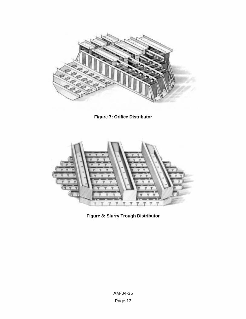
Figure 7: Orifice Distributor
Figure 8: Slurry Trough Distributor
AM-04-35
Page 13
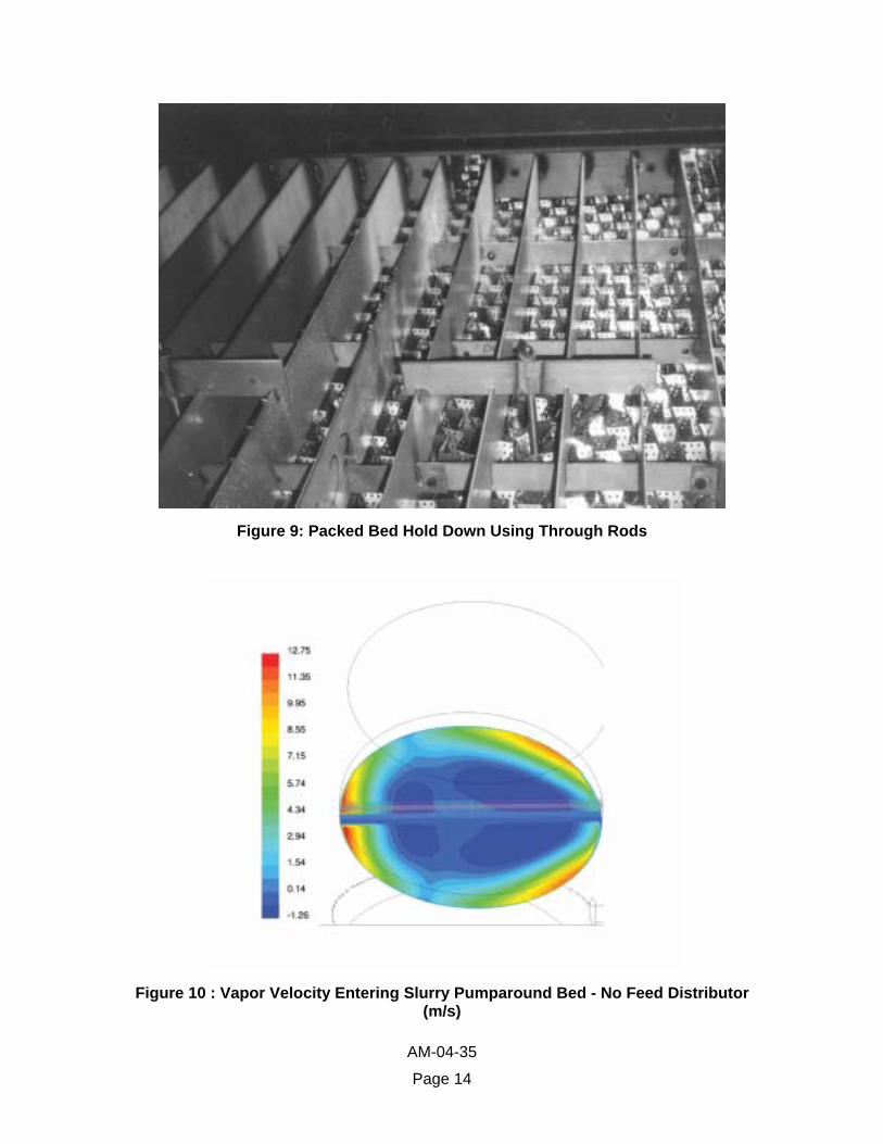
Figure 9: Packed Bed Hold Down Using Through Rods
Figure 10 : Vapor Velocity Entering Slurry Pumparound Bed - No Feed Distributor (m/s)
AM-04-35
Page 14
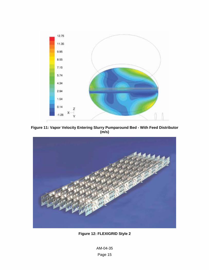
Figure 11: Vapor Velocity Entering Slurry Pumparound Bed - With Feed Distributor (m/s)
Figure 12: FLEXIGRID Style 2
AM-04-35
Page 15

Figure 13: FLEXIGRID Style 2 Removed From Slurry Pumparound
0
20000
40000
60000
80000
100000
120000
140000
5 10 15 20 25 30 35
Main Fractionator Diameterft
FCC
Rat
eM
BPD
Refinery A
Figure 14: North American FCC Capacity
AM-04-35
Page 16
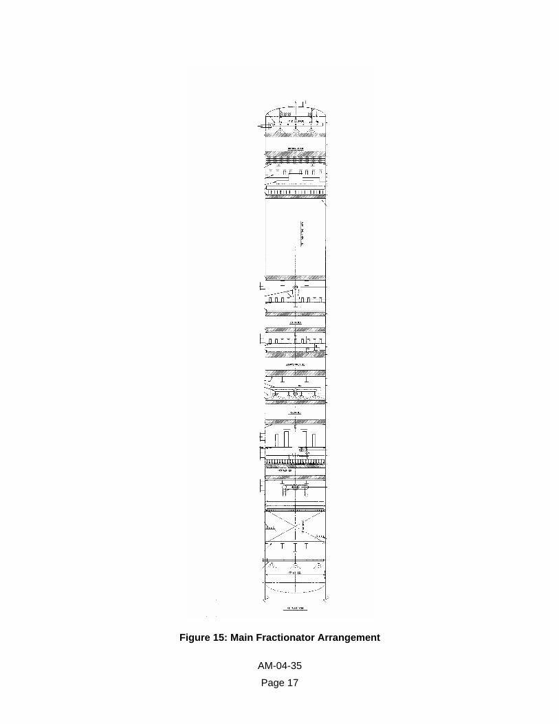
Figure 15: Main Fractionator Arrangement
AM-04-35
Page 17

Figure 16: Flash Box Supported Using Feed Pipe and Existing Tower Attachments
150
200
250
300
350
400
450
500
550
600
30% 35% 40% 45% 50% 55% 60% 65% 70% 75% 80%
LV% Products
Tem
pera
ture
, °F
Naphtha Distillation Pre TurnaroundLCO Distillation Pre TurnaroundNaphtha Distillation Post TurnaroundLCO Distillation Post Turnaround
Figure 17: FCCU Main Fractionator Naphtha & LCO D-2887 Distillations
AM-04-35
Page 18
AM-04-35
Page 19
1 Golden, S. W., Martin, G. R., and Sloley, A. W., FCC Main Fractionator Revamps,
Hydrocarbon Processing, March, 1993, pp. 77-81. 2 Laird, D., Fractionation Impact on FCC Gasoline and LCO Sulfur Content, NPRA Annual
Meeting, March 17-19, 2002, Paper AM-02-08. 3 Keyworth, D. A., Reid, T. A., Asim, M. Y., and Gilman, R. H., Offsetting the Cost of Lower
Sulfur in Gasoline, NPRA Annual Meeting, March 22-24, 1992, Paper AM-92-17. 4 Mayo, S., Leliveld, B., Plantenga, F., and Miyauchi, Y. A., Elegant Solutions for Ultra Low
Sulfur Diesel, NPRA Annual Meeting, March 18-20, 2001, Paper AM-01-09. 5 Hartman, E. L., Hanson, D. W., and Weber, B., FCCU Main Fractionator Revamp for CARB
Gasoline, Hydrocarbon Processing, February, 1998, pp. 44-49. 6 Sloley, A. W., Cat Naphtha Sulfur Management: Undercut or Not?, Hydrocarbon Processing,
February, 2001, pp. 75-78. 7 Tippett, T., Knudsen, K. G., and Cooper, B. H., Ultra Low Sulfur Diesel: Catalyst and Process
Options, NPRA Annual Meeting, March 21-23, 1999, Paper AM-99-06. 8 FRI Topical Report No. 133, July, 1999. 9 FRI Topical Report No. 125, January, 1997. 10 Stupin, W. J., and Kister, H. Z., System Limit: The Ultimate Capacity of Fractionators, Trans.
Institution of Chemical Engineers, Vol. 81, Part A, January, 2003, pp. 136-146.