Embed Size (px)
Citation preview

701 S. RIDGE AVENUETROY, OHIO 45374-0001
937 332-3000
www.hobartcorp.com FORM 35320 Rev. E (October 2012)
AM SELECT DISHWASHERS
MODELS
AM15 ML-130038AM15F ML-130045AM15T ML-130039
AM15VL ML-130153AM15VLF ML-130155AM15VLT ML-130154

– 2 –
POST IN A PROMINENT LOCATION THE INSTRUCTIONS TO BE FOLLOWED IN THE EVENT THE SMELL OF GAS IS DETECTED. THIS INFORMATION CAN BE OBTAINED FROM THE LOCAL GAS SUPPLIER.
IMPORTANT
IN THE EVENT A GAS ODOR IS DETECTED, SHUT DOWN UNIT(S) AT MAIN SHUTOFF VALVE AND CONTACT THE LOCAL GAS COMPANY OR GAS SUPPLIER FOR SERVICE.
FOR YOUR SAFETY
DO NOT STORE OR USE GASOLINE OR OTHER FLAMMABLE VAPORS OR LIQUIDS IN THE VICINITY OF THIS OR ANY OTHER APPLIANCE.
© HOBART CORPORATION, 2009
PRESSURE GAUGE
Model AM15 Model AM15F Model AM15T
Fig. 1
Model AM15VL Model AM15VLF Model AM15VLT

– 3 –
TABLE OF CONTENTS GENERAL . . . . . . . . . . . . . . . . . . . . . . . . . . . . . . . . . . . . . . . . . . . . . . . . . . . . . . . . . . . . . . . . . . . . 4 INSTALLATION . . . . . . . . . . . . . . . . . . . . . . . . . . . . . . . . . . . . . . . . . . . . . . . . . . . . . . . . . . . . . . . . 5 Unpacking . . . . . . . . . . . . . . . . . . . . . . . . . . . . . . . . . . . . . . . . . . . . . . . . . . . . . . . . . . . . . . . . . 5 Installation Codes . . . . . . . . . . . . . . . . . . . . . . . . . . . . . . . . . . . . . . . . . . . . . . . . . . . . . . . . . . . 5 Location . . . . . . . . . . . . . . . . . . . . . . . . . . . . . . . . . . . . . . . . . . . . . . . . . . . . . . . . . . . . . . . . . . . 5 Corner Installation . . . . . . . . . . . . . . . . . . . . . . . . . . . . . . . . . . . . . . . . . . . . . . . . . . . . . . . . . . . 6 Water Requirements . . . . . . . . . . . . . . . . . . . . . . . . . . . . . . . . . . . . . . . . . . . . . . . . . . . . . . . . . 7 Plumbing Connections . . . . . . . . . . . . . . . . . . . . . . . . . . . . . . . . . . . . . . . . . . . . . . . . . . . . . . . . 8 Drain Connection . . . . . . . . . . . . . . . . . . . . . . . . . . . . . . . . . . . . . . . . . . . . . . . . . . . . . . . . 8 Water Connection . . . . . . . . . . . . . . . . . . . . . . . . . . . . . . . . . . . . . . . . . . . . . . . . . . . . . . . . 8 Without Electric Booster Water Heater - Models AM15, AM15F, and AM15T. . . . . . . . . . . 8 With Electric Booster Water Heater - Models AM15, AM15F, and AM15T . . . . . . . . . . . . . 9 With Electric Booster Water Heater - Models AM15VL, AM15VLF, and AM15VLT . . . . . . . 9 GasTankHeat(WhenSpecified) . . . . . . . . . . . . . . . . . . . . . . . . . . . . . . . . . . . . . . . . . . . . . . 10 Venting Requirements - with Gas Tank Heat . . . . . . . . . . . . . . . . . . . . . . . . . . . . . . . . . . . . . . 11 Rate of Exhaust Flow Calculations . . . . . . . . . . . . . . . . . . . . . . . . . . . . . . . . . . . . . . . . . . 12 Table A Heat Dissipation . . . . . . . . . . . . . . . . . . . . . . . . . . . . . . . . . . . . . . . . . . . . . . . . . . 13 Electrical Connections . . . . . . . . . . . . . . . . . . . . . . . . . . . . . . . . . . . . . . . . . . . . . . . . . . . . . . . 14 Dishwasher without Electric Booster . . . . . . . . . . . . . . . . . . . . . . . . . . . . . . . . . . . . . . . . 15 MotorRotation(Three-PhaseMachinesOnly) . . . . . . . . . . . . . . . . . . . . . . . . . . . . . . . . . 15 DishwasherWithElectricBooster(SeparatelyConnected) . . . . . . . . . . . . . . . . . . . . . . . 15 DishwasherWithElectricBooster(SinglePointElectricalConnection) . . . . . . . . . . . . . . 16 Equipment Connections . . . . . . . . . . . . . . . . . . . . . . . . . . . . . . . . . . . . . . . . . . . . . . . . . . . . . . 16 Vent Fan Control . . . . . . . . . . . . . . . . . . . . . . . . . . . . . . . . . . . . . . . . . . . . . . . . . . . . . . . . 16 Remote Booster Control . . . . . . . . . . . . . . . . . . . . . . . . . . . . . . . . . . . . . . . . . . . . . . . . . . 16 Detergent, Rinse Aid, Sanitizer Dispensers — Tubing Installation . . . . . . . . . . . . . . . . . . . . . 17 Detergent Dispenser . . . . . . . . . . . . . . . . . . . . . . . . . . . . . . . . . . . . . . . . . . . . . . . . . . . . . 17 Rinse Aid Dispenser . . . . . . . . . . . . . . . . . . . . . . . . . . . . . . . . . . . . . . . . . . . . . . . . . . . . . 18 Chemical Sanitizer Dispenser - AM15, AM15F, and AM15T Models Only . . . . . . . . . . . . 18 Detergent, Rinse Aid, Sanitizer Dispensers — Equipment connections . . . . . . . . . . . . . . . . . 19 DetergentDispenser(Fig.22) . . . . . . . . . . . . . . . . . . . . . . . . . . . . . . . . . . . . . . . . . . . . . 19 RinseAid/SanitizerDispenser(s)(Fig.22) . . . . . . . . . . . . . . . . . . . . . . . . . . . . . . . . . . . 19 Setup(AM15,AM15F,andAM15TModelsOnly) . . . . . . . . . . . . . . . . . . . . . . . . . . . . . . . . . . 20 Sanitizing Mode . . . . . . . . . . . . . . . . . . . . . . . . . . . . . . . . . . . . . . . . . . . . . . . . . . . . . . . . 20 End of Cycle Buzzer - All Models . . . . . . . . . . . . . . . . . . . . . . . . . . . . . . . . . . . . . . . . . . . 20 OPERATION . . . . . . . . . . . . . . . . . . . . . . . . . . . . . . . . . . . . . . . . . . . . . . . . . . . . . . . . . . . . . . . . . 21 Preparation . . . . . . . . . . . . . . . . . . . . . . . . . . . . . . . . . . . . . . . . . . . . . . . . . . . . . . . . . . . . . . . 21 Dishwashing . . . . . . . . . . . . . . . . . . . . . . . . . . . . . . . . . . . . . . . . . . . . . . . . . . . . . . . . . . . . . . 22 CLEANING . . . . . . . . . . . . . . . . . . . . . . . . . . . . . . . . . . . . . . . . . . . . . . . . . . . . . . . . . . . . . . . . . . 24 For Models AM15VL,AM15VLF and AM15VLT: . . . . . . . . . . . . . . . . . . . . . . . . . . . . . . . . . . . . 25 Delime Instructions . . . . . . . . . . . . . . . . . . . . . . . . . . . . . . . . . . . . . . . . . . . . . . . . . . . . . . . . . 27 Dos and Don'ts for Your New Hobart Warewasher . . . . . . . . . . . . . . . . . . . . . . . . . . . . . . . . . 27 MAINTENANCE . . . . . . . . . . . . . . . . . . . . . . . . . . . . . . . . . . . . . . . . . . . . . . . . . . . . . . . . . . . . . . 28 Wash arms . . . . . . . . . . . . . . . . . . . . . . . . . . . . . . . . . . . . . . . . . . . . . . . . . . . . . . . . . . . . . . . . 28 Motor(s) . . . . . . . . . . . . . . . . . . . . . . . . . . . . . . . . . . . . . . . . . . . . . . . . . . . . . . . . . . . . . . . . . . 28 Flue(MachinesEquippedWithGasTankHeatOnly) . . . . . . . . . . . . . . . . . . . . . . . . . . . . . . 28 TROUBLESHOOTING . . . . . . . . . . . . . . . . . . . . . . . . . . . . . . . . . . . . . . . . . . . . . . . . . . . . . . . . . 28 Manual Reset Button on Pump Motor . . . . . . . . . . . . . . . . . . . . . . . . . . . . . . . . . . . . . . . . . . . 28 SERVICE . . . . . . . . . . . . . . . . . . . . . . . . . . . . . . . . . . . . . . . . . . . . . . . . . . . . . . . . . . . . . . . . . . . . 31

– 4 –
Installation, Operation and Care OfAM SELECT DISHWASHERS
SAVE THESE INSTRUCTIONS
GENERALModelsAM15,AM15VL,AM15T,andAM15VLTdishwasherscanbeconfiguredfor both straight through or corner operation. Models AM15F and AM15VLF are configuredforfrontloading.AM15,AM15VL,AM15T,andAM15VLTdishwashersare shipped from the factory in straight-throughconfiguration.Straight-throughmachines can easily be converted to corner operation. Models AM15F and AM15VLF include a front-loader shelf and left- and right-side shields as standard equipment. The front-loader shelf on the AM15F and AM15VLF can be positioned up (inside themachineduringoperation)ordown(outsidethemachineduringoperation).
The AM15, AM15F and AM15T dishwashers are designed to operate in one of two modes: Hot water sanitizing mode (designated by the letters “AH” or “AP” on the displaywhenthemachineisturnedon),orachemicalsanitizingmode(designatedbythe letters“AC”onthedisplaywhenthemachineisturnedon).AM15VL,AM15VLFand AM15VLT dishwashers are designed to operate in hot water sanitizing mode only(designatedbytheletters“HL”onthedisplaywhenthemachineisturnedon).
The serial number can be found on the machine data plate located on the bottom of the front panel. The pump motor is rated 2 H.P. and has thermal overload protection.
DO NOT attempt to operate this dishwasher in the chemical sanitizing mode without aproperlyinstalled,NSFCertified,chemicalsanitizerfeeder(customersupplied).Contact an authorized detergent representative for information about a chemical sanitizer feeder.
Thefilllineincorporateseitheranatmosphericvacuumbreakerfornon"VL"models oranairgapfor"VL"modelstopreventanyreverseflowofwaterfromthedishwasherintothepotablewatersupply.Theunit,onceturnedon,fillsthewashtanktotheappropriatelevelandautomaticallystopsfillingoncethelevelisreached.Afloat,located in the wash tank, shuts off the heat supply if the water level becomes too low. When the water returns to the proper level, the heating circuit is again operational.
A frame-mounted 8.5 kW electric booster water heater is available as an option for models equipped with electric tank heat. The booster water heater is standard for"VL"models.FormodelsAM15,AM15F,andAM15Ttheboosterwaterheaterisdesignedtomaintainaminimumfinalrinsetemperatureof180°Fprovidedtheincomingwatertotheboosterheaterisatleast110°F.ForventlessmodelsAM15VL,AM15VLF, and AM15VLT, the booster water heater is designed to maintain a minimum finalrinsetemperatureof180°Fwithcoldincomingwater.
Ventless models AM15VL, AM15VLF, and AM15VLT do not require a vent hood. They use an internal condensing system to minimize the water vapor escaping from the unit during loading and unloading. High-temperature AM15, AM15F and AM15T models or gas heat dishwashers typically require a hood or vent over the dishwasher to meet local codes. Low-temperature chemical sanitizing machines or low usage electric heat dishwashers may not require individual venting of the machine if the room is amply exhausted. Refer to pages 10 and 11 for venting and hoodrequirements.Verifywithlocalcodesforfinalauthority.

– 5 –
INSTALLATIONUNPACKING
Immediately after unpacking the dishwasher, check for possible shipping damage. If this machine is found to be damaged, save the packaging material and contact the carrier within 15 days of delivery.
Prior to installation, test the electrical service to make sure it agrees with the specificationsonthemachinedataplate;thisincludestheoptionalelectricbooster, if equipped. The dishwasher data plate is located at the bottom of the front panel.
INSTALLATION CODES
Installation must be in accordance with state and local codes, or in the absence of localcodes,withtheNationalFuelGasCode,ANSIZ223.1(latestedition) ifapplicable,and theNationalElectricalCodeANSI/NFPA70 (latestedition). InCanada, the installation standards are: CAN/CGA B149.1, CAN/CGA B149.2, and CSAC22.2No.1(latesteditions).
LOCATION
Beforefinalizingthelocation,makesurethatconsiderationhasbeengivenforthe electrical conduit, water supply, drain connection, gas supply and venting (if applicable),tabling(ifneeded),chemicalfeederreplenishment(ifapplicable)andadequate clearance for opening the door.
The dishwasher must be level before any connections are made. Turn the threaded feet(Fig.2)asrequiredtolevelthemachineandadjusttothedesiredheight.
The edge of dish table that overhangs the AM15 wash tank should be turned down andfittedoverthetopofthedishwashertank(Fig.3).ApplyanNSFapprovedsealant between the overhang of the dish table and the inner wall of the wash tank topreventleakage(Fig.3).Fastenthedishtablestotheinnerwallofthewashtankwithnon-rustingtrussheadscrewsorrivets(Fig.3).
For straight-through installations, clearance at the front and 15 inches out from the dishwasherattherightsideby27inchesabovethefinishedfloormustbeprovidedfor servicing.
Fig. 2
Fig. 3
WASH TANKDISH TABLE
DISH TABLE
STRAIGHT-THROUGH OPERATION SHOWN
INNER WALL OF WASH TANK
SEALANT
NUT
DISH TABLE
MACHINE SCREW OR RIVET

– 6 –
CORNER INSTALLATION
Beforeplacingthedishwasherinitsoperatinglocation,checkmachineconfiguration.Ifthemachineisbeinginstalledinacorner(Figs.4,5),clearancesof20inchesoutfromthedishwasherundertheleft-handtablingby27inchesabovethefinishedfloorand15inchesoutfromthedishwasherattherightsideby27inchesabovethefinishedfloormustbeprovidedforservicing.Forproperinstallationofacornermachine, the control and display should be positioned at the front corner for operator access(Fig.5).
For corner installation, rotate the rack track so the guide rail is positioned on the leftside(Fig.6).Forcornermachines,removethefrontdoordeflector(unscrewthreebolts/nuts,Fig.7).
Fig. 6 Fig. 7
Fig. 4 Fig. 5
WASH TANKDISH TABLE
DISH TABLE
CORNER OPERATION SHOWN
DISH TABLE
INNER WALL OF WASH TANK
SEALANT
MACHINE SCREW OR RIVET
NUT
CONTROLS MUST BE ACCESSIBLE AT FRONT CORNER.

– 7 –
WATER REQUIREMENTS
Proper water quality can improve warewashing performance by reducing spotting, lowering chemical supply costs, improving productivity and extending equipment life. Local water conditions vary from one location to another. The recommended proper water treatment for effective and efficient use of this equipment willalso vary depending on the local water conditions. Ask your municipal water supplierfordetailsaboutlocalwaterspecificspriortoinstallation.
Recommended water hardness is 3 grains of hardness per gallon or less. Chlorides must not exceed 30 parts per million. Water hardness above 3 grains per gallon shouldbetreatedbyawaterconditioner(watersoftenerorin-linetreatment).Watertreatment has been shown to reduce costs associated with machine cleaning, reduce the need for deliming the dishwasher and reduce detergent usage.
Sediment, silica, chlorides or other dissolved solids may lead to a recommendation forparticulatefiltrationorreverseosmosistreatment.
If an inspection of the dishwasher or booster heater reveals lime build-up after the equipment has been in service, in-line water treatment should be considered, and, if recommended, should be installed and used as directed. Contact your Hobart Serviceofficeforspecificrecommendations.
A NOTCH MUST BE ADDED TO BACKSPLASHES OVER6"HIGHONCORNERMACHINESTOPREVENTINTERFERENCE WITH DOOR MECHANISM. NOTCH MUSTEXTEND5"FROMFACEOFTHEMACHINE.
Asplashshieldisavailable(atextracost)forcornerinstallationstocovertheleftsideopeningtothewall.Installthesplashshieldontheleftsideusingthetwo1⁄4-20studsontheleftrearcornerwithalockwasherandnutforeach(Fig.8)andusingthetwo1⁄4-20bolts,lockwashersandnutsontheleftfrontcorner(fastenersareprovidedinthekit).
Forcornerinstallations,tablingwithbacksplashesover6"highrequirethatanotchbeprovidedtopreventinterferencewiththedoormechanism(Fig.9).
Fig. 8 Fig. 9

– 8 –
PLUMBING CONNECTIONS
Plumbing connections must comply with applicable sanitary, safety, and plumbing codes.
Drain Connection
The drain connection is a 11⁄2 inch externally threaded pipe connected straightdownfromthebottomofthewashtank(Fig.10).Theconnectioncanbemadeinanydirectionbyusingtheproperfitting(notsupplied)androutingtotheappropriate drain line.
Ifagreasetrapisrequiredbycode,itshouldhaveaminimumflowcapacityof38gallons per minute.
Water Connection
Asuitablewaterhammerarrestorshouldbeinstalledinthewaterlinejustaheadof the dishwasher.
Without Electric Booster Water Heater - Models AM15, AM15F, and AM15T
Thewatersupplylineisconnectedtothelinestrainer(toprear,Fig.1)with3⁄4inchor1⁄2inchpipe.Amanualshutoffvalveandpipeunionarerequired(customersupplied).
For AM15, AM15F, and AM15T models, proper dishwasher operation requires a flowingpressureof20±5psigatthedishwasher.Iftheflowingpressureexceeds25psig,apressurereducingvalve(customersupplied)mustbeinstalledinthewatersupplyline.Apressuregauge(Fig.1)isprovided(notinstalled)forverificationofproper water pressure. The water pressure is monitored when the solenoid valve isopenandwaterisflowing.
The water pressure regulator must have a relief by-pass. Failure to use the proper type of pressure regulator may result in damage to the unit.
Fig. 10
REQUIRED INCOMING WATER TEMPERATURE
Model Sanitizing Mode ConnectionWater Supply
Minimum Maximum RecommendedWithout Built-in
BoosterHot Water Sanitizing Hot Water 180°F(82°C) 194°F(90°C) 180°F(82°C)
Without Built-in Booster Chemical Sanitizing Hot Water 120°F(49°C) N/A 140°F(60°C)
With Built-in Booster Hot Water Sanitizing Hot Water 110°F(43°C) N/A 140°F(60°C)
VL Models Hot Water Sanitizing
Cold Water N/A 90°F(32°C) 65°F(18°C)Hot Water 110°F(43°C) N/A 140°F(60°C)

– 9 –
With Electric Booster Water Heater - Models AM15, AM15F, and AM15T
Thewatersupplylineisconnectedbelowtheboosterwiththelinestrainer(supplied) and3⁄4inchpipe.Amanualshutoffvalveandpipeunionarerequired(notsupplied).
Thewatersupplymusthaveaminimumtemperatureof110°F(43°C),andaflowingpressureof20±5psigatthepressuregaugeontopofthemachine.Iftheflowingpressureexceeds25psig,apressurereducingvalve(notsupplied)mustbeinstalledin the water supply line.
The water pressure regulator must have a relief by-pass. Failure to use the proper type of pressure regulator may result in damage to the unit.
Incomingwatertemperaturebelow110°F(43°C)mayrequirelongerwashcycletimethanthe57secondcycle;refertoOPERATION, pages 17 – 18.
Whenthefill/finalrinsevalveison,waterfromtheboostertankentersthedishwasherthroughthefinalrinsearms.Duringtherinsecycle,thiswateris180°F(82°C). A small amount of water will likely dribble out of the lower rinse arm into the tank between cycles due to the natural expansion of water as it is being heated.
With Electric Booster Water Heater - Models AM15VL, AM15VLF, and AM15VLT
Ventless models require both a cold water supply connection and a hot water supply connection. The cold water supply line is connected to the line strainer at the top of the machine with a 1⁄ 2 inch pipe. A pressure regulator and pressure gauge are not required.Amanualshut-offvalveandpipeunionarerequired(customersupplied).
Thecoldwatersupplymustnotexceed90°F(32°C)forproperoperation.Optimalresultsareobtainedwhencoldwatersupplytemperatureisbelow65°F(18°C).Forbestresults,itmaybenecessarytouse1⁄ 2 inch pipe for the cold water pipe size and minimize the distance between the dishwasher and the entrance into the building. Pipe insulation will also improve results.
Ifcoldwatersupplytemperatureisconsistentlyabove90°F(32°C)orifexcessivewater vapor or steam is entering the room after the condensing cycle is complete, contact Hobart Service to increase condensing time.
The hot water supply line is connected to the line strainer at the rear of the machine with a 1⁄ 2 inch pipe. A pressure regulator and pressure gauge are not required as this is a pumped rinse machine. A manual shut-off valve and pipe union are required (customersupplied).

– 10 –
GAS TANK HEAT (WHEN SPECIFIED)
Check the gas data plate attached to the dishwasher or the tag attached to the incominggaspipingforthetypeofgastobeused.Theburnerisnotadjustable.ThemaximumflowinginletgaspressuremustnotexceedtheMaximumvalueinthe table. If line pressure exceeds the Maximum value in the table, an additional pressureregulator(notsupplied)mustbeinstalledinthesupplyline.
Static inlet line pressure should not exceed 14 inches W.C. The minimum value isforinputadjustment.
The gas valve is provided with a pressure tap to measure the gas pressure downstream, which is also the manifold pressure. Gas supply piping must have a sediment trap (suppliedbyothers)installedaheadofthedishwasher’sgascontrol.Connectthegas supplytothe1⁄2inchNPTgasinletunderneaththemachine(Fig.11).
Do not use Teflon tape on gas line pipe threads. For gas line pipe connections, use Loctite 565, Hobart part 546292, or a flexible sealant suitable for use with Natural and Propane Gases.
The appliance and its gas connections must be leak tested before placing the appliance in operation. Use soapy water for leak test. Do notuseopenflame.The installation must conform with local codes, or in the absence of local codes, withtheNationalFuelGasCode,ANSIZ223.1(latestedition). Copiesmaybeobtained from American Gas Association, Inc., 1515 Wilson Boulevard, Arlington, VA 22209.
The appliance and its individual shutoff valve must be disconnected from the gas supply piping system during any pressure testing of that system at test pressures in excess of 1⁄2psig(3.45kPa).
The appliance must be isolated from the gas supply piping system by closing its individual manual shutoff valve during any pressure testing of the gas supply piping system at test pressures equal to or less than 1⁄2psig(3.45kPa).Dissipatetest pressure from the gas supply line before re-connecting the appliance and its manual shutoff valve to the gas supply line.
Failure to follow this procedure may damage the gas valve.
Fig. 11
GAS PRESSURE SPECIFICATION[FLOWING GAS PRESSURE — NOT STATIC]
Type of
GasBTU/HR
Inches W.C. (Water Column) FLOWINGIncoming Line Pressure Manifold
PressureMinimum MaximumNatural 25,000 3.5 7.0 3.2Propane 25,000 9.0 11.0 8.2

– 11 – Fig. 12 Fig. 13
31⁄2"
6" ➤
➤
➤ ➤
➤
➤
4"
➤ 3" x 3" DUCT INTOCURRENT SYSTEM
➤
5"GAPMINIMUM
➤
➤MINI VENT HOOD
DISHWASHER FLUE EXIT
➤
➤
➤
6"MINIMUM OVERHANGON ALL SIDES
➤
➤
1' TO 4' CLEARANCE
➤
➤
18"OVERHANGRECOMMENDED OVER LOADING OR UNLOADING DOORS
Thedishwashermustbeinstalledsothattheflowofcombustionandventilationair isnotobstructed.Donotstorematerialunderneaththemachine;airopeningsinto the combustion chamber must not be blocked. Make sure there is an adequate supply of make-up air in the room to allow for combustion of the gas at the burner.
Keep the appliance area free and clear from all combustible substances. Do not obstruct the flow of combustion and ventilation air. The dishwashermust have a minimum clearance from combustible construction of 1 inch from theflueat the rear. Clearancesof20 inchesout from thedishwasherat the front (or left side in a corner installation) by 27 inches above the finishedfloor and 15 inches out from the dishwasher at the right side by 27 inchesabove the finished floormust beprovided for servicing. Theburner is ignitedautomaticallybysolidstateelectroniccircuitry; there isnopilot light. Gasflow is regulated by the temperature control circuit.
VENTING REQUIREMENTS — WITH GAS TANK HEAT
Hobart model AM15, AM15F or AM15T dishwashers equipped for gas tank heat arenotprovidedwithafluecollarandarenotintendedtohavethefluedirectlyconnected to a ventilation system. However, the products of combustion must be vented to the outside air. The most common method of venting is a vent hood over theentiredishwasher(Fig.12).RefertoRateofExhaustFlowCalculationsonthenext page for calculations of the proper vent rate for your hood. Another method isasmallventhood(Fig.13)positionedaboutfiveinchesabovetheflueexitatthe rear of the dishwasher and connected to existing ductwork. In either case, anelectricalinterlockmustbeinstalledtoallowtheflowofgastothedishwasherburner ONLY when the exhaust system is energized. For additional information, refer to the National Fuel Gas Code, ANSI Z223.1, NFPA 54.
Make sure the installation meets the local code for your area.

– 12 –
NOTE: Any listed and labeled factory-built commercial exhaust hood tested in accordance with UL Standard 710 by a nationally recognized testing laboratory, must be installed according to the terms of its listing and the manufacturer’sinstallation instructions.
Rate of Exhaust Flow Calculations
Based on the 2009 International Mechanical Code.
TheminimumnetairflowforTypeIIhoodsusedfordishwashingappliancesshallbe 100 cfm per linear foot of hood length. The net quantity of exhaust air shall be calculatedbysubtractinganyairflowsupplieddirectlytoahoodcavityfromthetotalexhaustflowrateofahood.
Ventless models AM15VL, AM15VLF, and AM15VLT do not require a Type II vent hood. According to 507.22 of the 2009 IMC, Type II hoods are not required where the heat and moisture load is incorporated into the HVAC system design. See Table A for heat dissipation or heat gain to space.
➤➤ LENGTH
➤
➤
CLEARANCEHEIGHT
➤
➤WIDTH
Fig. 14

– 13 –
TABLE A: HEAT DISSIPATION
Model Electric Heat
Gas Heat
13 kW Electric Booster
8.5 kW Electric Booster
Steam Booster
Latent Heat (BTU/HR)
Sensible Heat (BTU/HR)
Hot Water
Sanitizing
AM15
X 7,400 3,200
X X 22,900 9,800
X X 17,500 7,500
X X 27,800 11,900
X 10,900 4,700
X X 31,200 13,400
AM15T, AM15F
X 10,400 4,400
X X 32,100 13,800
X X 24,600 10,500
X X 38,900 16,700
X 15,200 6,500
X X 43,700 18,700
AM15, AM15T, AM15F with power
vent fan option
X 1,200 1,300X X 3,700 4,200X X 2,800 3,200X X 4,500 5,100
X 1,800 2,000X X 5,000 5,700
AM15VL X X 9,300 3,400AM15VLT, AM15VLF X X 13,000 4,800
Chemical Sanitizing
AM15X 9,400 2,800
X 10,900 4,600
AM15T, AM15FX 13,200 3,900
X 15,200 6,500
Assumptions: 1. Machines operate 70% of each hour while in use. 2. All heat dissipated enters the room except for models with power vent fan
option and gas heat models. Gas heat models must be provided with vent hood which directs 40% of heat to outside atmosphere.
3. 70% of heat output is latent, 30% is sensible. 4. Chemical sanitizing models operate at 60% of the heat output of equivalent
hot water sanitizing models.

– 14 –
ELECTRICAL DATA
Models Volts / Hz / Ph Tank Heat
Minimum Circuit AmpacityMaximum Protective Device
AMPS
Dishwasher ONLY
Optional 8.5 KW Electric Booster
8.5 KW Booster
ONLY
Optional Single PointElectrical Connection
3 Phase Only Dishwasher and
BoosterAM15
AM15FAM15T
208 - 240 / 60 / 1 Gas 20208 - 240 / 60 / 3 Gas 15
480 / 60 / 3 Gas 15AM15, AM15F
AM15T, AM15VLAM15VLF, AM15VLT
208 - 240 / 60 / 1 Electric 50 50208 - 240 / 60 / 3 Electric 30 30 60
480 / 60 / 3 Electric 15 15 30
AM15, AM15F, AM15T
200 - 240 / 50 / 3 Electric 30 30 60380 - 415 / 50 / 3 Electric 15 15 30
Compiledinaccordancewiththenationalelectricalcode,NFPA70(latestedition).
ELECTRICAL CONNECTIONS
Electrical and grounding connections must comply with the applicable portions of the National Electrical Code, NFPA 70 (latest edition) and / or other local electrical codes.
Disconnect the electrical power to the machine (both dishwasher and booster if applicable) and follow lockout / tagout procedures. Be sure all circuits are disconnected.
Refer to the wiring diagram attached inside the front trim panel and to the machine data plate for service size requirements when connecting the dishwasher. Also, refer to Electrical Data, page 12.
To access the controls area, remove the right side panel, remove the front panel and open the control panel door. The dishwasher electrical service connection can be made through the 13 ⁄ 32 inch diameter hole for 3 ⁄4 inch trade size conduit located on the right side at the rear of the machine. By removing a knockout, this hole can be enlarged to 13 ⁄ 8"diameterfor1inchtradesizeconduit,ifrequired.
Afuseddisconnectswitchorcircuitbreaker(customersupplied)mustbeinstalledin the electrical service line(s) supplying this dishwasher and shouldmeet therequirements of your local electrical code.

– 15 –
Dishwasher without Electric Booster
For single-phase machines, power supply connections are made to terminal blocks. For three-phase machines connections are made to contactor lugs. The machine mustbegroundedaccordingtoelectricalcode(s);agroundinglugisprovidedinthe controls area. Electrical connections for machines with gas tank heat are made to contactor 1CON in the controls area.
Motor Rotation (Three-Phase Machines Only)
Three-phase motors must rotate in the direction of the arrow on the pump housing. In order to check rotation, remove the bearing cap to observe the motor shaft (Fig.15).ClosethemachinedoorsandpressthepowerswitchtoON.Whenthemachineiscompletelyfilled,openandclosemachinedoorstoverifythatthemotorshaft rotates in the clockwise direction.
If the rotation is incorrect, DISCONNECT ELECTRICAL POWER SUPPLY and interchange any two of the incoming power supply leads. Reconnect the power supply and verify correct rotation. Replace the motor bearing cap.
Dishwasher With Electric Booster (Separately Connected)
Single phase machines with an electric booster require two separate connections, one for the booster and the other for the dishwasher (including motor, controls and tankheat).Forsingle-phasemachines,allpowersupplyconnectionsaremadetoterminalblocks(Fig.16).Thesinglephasedishwasherisconnectedtoterminalblock 1TB in the controls area. The single phase booster is connected to terminal block 2TB in the controls area.
If the machine is three phase, the electrical connection for the dishwasher is made to the contactor 2CON in the controls area The electrical connection for the three phaseboosterismadetothecontactor3CONinthecontrolsarea(Fig.17).
Fig. 15

– 16 –
Dishwasher With Electric Booster (Single Point Electrical Connection)
Threephasemachinesconfiguredwiththeoptionalsinglepointelectricalconnectionareconnectedtoterminalblock1TBinthecontrolsarea(Fig.18).Themachinemustbegroundedaccordingtoelectricalcode(s);agroundinglugisprovided.
Fig. 16 Fig. 17 Fig. 18
EQUIPMENT CONNECTIONS
Electrical and grounding connections must comply with the applicable portions of the National Electrical Code, NFPA 70 (latest edition) and / or other local electrical codes.
Disconnect the electrical power to the machine (both dishwasher and booster if applicable) and follow lockout / tagout procedures. Be sure all circuits are disconnected.
Vent Fan Control
The vent fan control feature is standard on models AM15, AM15F, and AM15T. This feature is not available on ventless models AM15VL, AM15VLF, and AM15VLT. The vent fan control relay provides switch contacts only and does not provide power to the vent fan motor. The rating for a vent fan control relay connected to terminals VFC1 and VFC2 is 1.5 Amps at 240 Volts maximum. When the dishwasher is connected to the vent fan, the vent fan is switched on when the dishwasher is on, and off when the dishwasher is off.
Remote Booster Control
The booster control feature is standard on models AM15, AM15F, and AM15T. This feature is not available on ventless models AM15VL, AM15VLF, and AM15VLT. The load rating for remote booster control connections to BSTR1 and BSTR2 is 0.1 Amp. at 120 Volts maximum. The booster control provides a control signal only and does not provide power to the remote booster. When a remote booster is connected to the dishwasher, the booster is on when the dishwasher is on and off when the dishwasher is off.

– 17 –
DETERGENT, RINSE AID, SANITIZER DISPENSERS — TUBING INSTALLATION
Detergent,rinseaidand/orsanitizerdispensers(notprovidedbyHobart)musthaveall connections sealed against leakage.
Thedishwasheruses0.74gallonsofrinsewaterperrackataflowrateof4.4gallonsperminuteat20psigflowingpressure.Thisinformationisusedwhensettingthedetergent, rinse aid or sanitizer pumps.
NOTE: Ventless"VL"modelsdonothaveapressuregauge.
See Hobart form F15523 for sanitizer volumes and installation instructions.
Detergent Dispenser
The dishwasher has two 7⁄8 inch diameter plugged holes, one on the rear of the chamberandoneonthelowerpartofthetanknearthepump(Fig.19).Withthetank empty, remove both plugs to install the detergent dispenser.
• The chamber hole is for installation of the detergent feeder tube.
• The lower tank hole is used for installation of the detergent sensor.
Fig. 19
DETERGENT SENSOR PORT

– 18 –
Rinse Aid Dispenser
Therinselineflangeconnectorontopofthedishwasherhastwo1⁄8 inch NPT pipe plugs(Fig.20).
• Removetheplug(s)(Fig.20)forinstallationoftherinseaiddispensertubeand / or chemical sanitizer tube, as needed.
Chemical Sanitizer Dispenser - AM15, AM15F, and AM15T Models Only
When the dishwasher is to be operated in the chemical sanitizing mode, the machine must be converted to low-temperature sanitization (refer to Setup, page 16). Achemicalsanitizerdispenser thathasbeentestedandcertifiedbyNSFInternational must be installed.
• Removethepipeplug(Fig.20)forinstallationofthechemicalsanitizertube.To assureanunobstructedflowofsanitizer,locatethesanitizertubeinthecenterof waterflowbydrillingthesanitizertubefittingsothatitsinsidediameterisequal to the outside diameter of the tube.Slidethetubeintotheflangeuntilittouches the opposite side and then pull it back out 1⁄4inch(Fig.21).
• Rate for 6% Sodium hypochlorite (bleach) - 3 ml. within 10 seconds (maximum).
• Rate for 8.4% Sodium hypochlorite (bleach) - 2 ml. within 10 seconds (maximum).
Fig. 20
Fig. 21
PIPE PLUGS

– 19 –
DETERGENT, RINSE AID, SANITIZER DISPENSERS — EQUIPMENT CONNECTIONS
Electrical and grounding connections must comply with the applicable portions of the National Electrical Code, NFPA 70 (latest edition) and / or other local electrical codes.
Disconnect the electrical power to the machine (both dishwasher and booster if applicable) and follow lockout / tagout procedures. Be sure all circuits are disconnected.
This machine must be operated with an automatic detergent feeder and, if applicable, an automatic chemical sanitizer feeder, including a visual means to verify that detergents and sanitizers are delivered or a visual or audible alarm to signal if detergents and sanitizers are not available for delivery to the respective washing and sanitizing systems. Refer to the installation section of this manual and to the chemicalfeederequipmentmanual(s).
Detergent Dispenser (Fig. 22)
Terminals DPS1 and DPS2 are supplied with controlled machine line voltage. They are ON during the wash cycle and OFF between cycles or when the machine power supply is OFF Maximum rating for detergent dispenser connected to DPS1 and DPS2 is 1.5 Amps at line voltage. Check the machine supply voltage and use corresponding feeder transformer voltage. Use UL Listed 600 volt minimum insulated wire for the connections. Do not use bell wire, lamp cord or similar type wire. Splice connections, if required, must be made in the feeder transformer junctionbox-notinthemaincontrolsenclosure.Remove7⁄8"diametercapplug(s)for 1⁄2"tradesizeconduitfittingsfromtherearoftheenclosure.Removethesidepanel.Strainrelieffittingsmustbeprovidedforallwiring.
Rinse Aid / Sanitizer Dispenser(s) (Fig. 22)
Terminals RPS1 and RPS2 are supplied with controlled machine line voltage and are ON during the rinse cycle only. Maximum rating for rinse aid dispenser connected to RPS1 and RPS2 is 1.5 Amps at line voltage. Check the machine supply voltage and use corresponding feeder transformer voltage. Use UL Listed 600 volt minimum insulated wire for the connections. Do not use bell wire, lamp cord or similar type wire. Splice connections, if required, must be made in the feeder transformer junctionbox(suppliedbyothers)—notinthemaincontrolsenclosure.Remove7⁄8inchdiametercapplug(s)for1⁄2inchtradesizeconduitfittingsfromtherearoftheenclosure.Strainrelieffittingsmustbeprovidedforallwiring.
Fig. 22
— VFC1— VFC2— BSTR1— BSTR2— DPS1— DPS2— RPS1— RPS2
DETERGENTDISPENSER
TRANSFORMER
PRIM
ARY
SEC
ON
DA
RY
RINSE AGENTDISPENSER
CHEMICAL SANITIZERDISPENSER
RIGHT SIDE OF CONTROL AREA
TRANSFORMER
PRIM
ARY
SEC
ON
DA
RY
GROUND LUG

– 20 –
SETUP (AM15, AM15F, AND AM15T MODELS ONLY)
Sanitizing Mode
1. With the machine OFF, press and hold the OFF key.
2. Press and release the ON key.
The display initializes until 88 displays.
3. Release the OFF key.
SET X °F°C displays. X can be H, C or P:
H = Hot Water Sanitizing, Internal Booster.
C = Chemical Sanitizing, No Booster.
P = Hot Water Sanitizing, External Booster.
4. Press CYCLE to select P, H, or C as the sanitizing mode.
After 15 seconds, the selection is saved and the machine turns off.
End of Cycle Buzzer - All Models
1. With the machine OFF, press and hold the OFF key.
2. Press and release the ON key.
The display initializes until 88 displays.
3. Release the OFF key.
SET X °F°C displays. XcanbeP,HorC.(Seeabove).
5. Press and release the OFF key.
SET WASH XX displays. XX can be On or OF:
SET WASH On = End of Cycle Buzzer is ON.
SET WASH OF = End of Cycle Buzzer is OFF.
6. Press CYCLE to select On or OF for the End of Cycle Buzzer.
After 15 seconds, the selection is saved and the machine turns off.
SHORTCUT IF PROGRAMMING BOTH FEATURES
AT THE SAME TIME.
SET WASH OF
SET WASH On
SET C°F°C
SET P°F°C
SET H°F°C

– 21 –
OPERATIONPREPARATION
Theoverflowtubemustbeinitsproperlocationbelowthestrainerpan(Fig.23).Placethestrainerpanandthestrainerbucketintheirproperpositions(Fig.24).
Fig. 23
Anautomaticdetergentdispenserisrequired.Closelyfollowsupplier’sinstructions.
Closethedoor;thiswillautomaticallyclosethedrain.
Openthemanualgasvalve(ifapplicable).PresstheONbuttontoturnthepoweron(Fig.25).Ifthemachine’sdoorisclosedandnowaterisinthetank,thefillcyclewillbeginautomatically.Duringthefillcycle,thewordFILLisdisplayed.
Fig. 24
Fig. 25
– 22 –
When washing or in idle mode, the readout displays the wash temperature. During the rinse cycle, the rinse icon and temperature are displayed. Select the wash cycle: 1 for normal serving ware, 2, 4 or 6 for pots and pans. Each wash cycle is followed by an automatic rinse. When the rinse cycle is complete and the rinse icon turns off, the door can be opened.
For ventless models, the door must remain closed until the condensing cycle is complete and the cycle light turns off. A cycle countdown in seconds is displayed during the condensing cycle. Failure to follow these instructions will result in excess water vapor in the room.
DISHWASHING
Scrape the dishes to remove large particles of food and debris. Never use steel wool on ware to be loaded into the dishmachine.
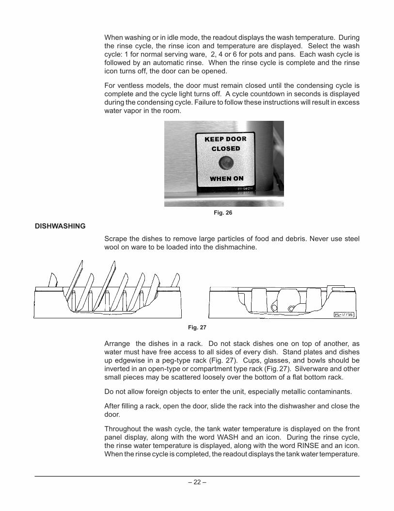
Arrange the dishes in a rack. Do not stack dishes one on top of another, as water must have free access to all sides of every dish. Stand plates and dishes upedgewiseinapeg-typerack(Fig.27).Cups,glasses,andbowlsshouldbeinvertedinanopen-typeorcompartmenttyperack(Fig.27).Silverwareandothersmallpiecesmaybescatteredlooselyoverthebottomofaflatbottomrack.
Donotallowforeignobjectstoentertheunit,especiallymetalliccontaminants.
Afterfillingarack,openthedoor,slidetherackintothedishwasherandclosethedoor.
Throughout the wash cycle, the tank water temperature is displayed on the front panel display, along with the word WASH and an icon. During the rinse cycle, the rinse water temperature is displayed, along with the word RINSE and an icon. When the rinse cycle is completed, the readout displays the tank water temperature.
Fig. 26
Fig. 27

– 23 –
On AM15VL, AM15VLF, and AM15VLT models, a countdown of the remaining cycle time, along with the rinse icon only, is displayed during a condense cycle.
Whenthecycleisfinishedandtherinseicondisappears,orthecondensingcyclelightgoesoutfor"VL"models,openthedoor,removethecleandishes,slideinanother rack and close the door.
To add a dish after the wash cycle has started, open the door slightly. Wait 10 seconds to allow the wash arm to coast down and to avoid water splashing before opening the door fully.
Operating temperatures for all models are as follows:
Model AM15F and AM15VLF have a front loader door and loading tray. The machine canoperatewiththeloadertraypositionedverticalinsidethechamber(upposition)orpositionedhorizontaloutsidethechamber(downposition).
For "VL"models only - If excessive amounts of steamorwater vapor exit themachine after condensing cycle light goes out and door is opened, incoming cold water temperaturemaybetoohigh.ContactHobartServicetoadjust therinseandcondensetimesaccordingtotheadjustmenttable.Increasingcycletimewillincrease water consumption and decrease the racks per hour, but should reduce the water vapor entering the room.
Sanitizing ModeWash Temperature Rinse Temperature
Minimum Wash Recommended Wash Minimum Rinse Recommended RinseHot Water 150°F(66°C) 150°F(66°C) 180°F(82°C) 180°F(82°C)
Chemical 120°F(49°C) 140°F(60°C) 120°F(49°C) 140°F(60°C)
Incoming Water
Temp.°F(°C)
Condense Time (Sec.)
Rinse Time (Sec)
Racks per Hour (1 min
cycle)60(16) 30 10 4065(18) 33 11 3870(21) 36 12 3775(24) 39 13 3580(27) 42 14 3485+(29+) 45 15 33
RECOMMENDED CONDENSE TIME (Based on Incoming Water Temp.)

– 24 –
CLEANINGThe machine must be thoroughly cleaned at the end of each working shift or at least daily. Never use steel wool to clean warewasher surfaces. Use only products formulated to be safe on stainless steel.
1. Push the OFF button.
2. Open the machine door.
3. Clean off the dish tables into the dishwasher.
4. Drain the machine by lifting up the drain lever.
5.Thoroughlycleanseandflushthedishwasherinterior.Removeremainingsoilwith a soft cloth or brush and mild cleanser. Rinse again.
6. Remove and empty the strainer bucket and pan. Wash and rinse them thoroughly.
7. Clean the pump cover with a soft cloth or brush. Do not allow food soil to accumulate on the tank bottom or to enter the drain.
8.Removetheoverflowtube.Washandrinsetheoverflowtubeinsideandout.
9. Make sure that the wash and rinse arms rotate freely and are free of any obstructions. If not, remove arms and clear out any obstructions.
10.Removeandcheckwasharmsandrinsenozzles(Figs.29,30)tomakesurethey are free of any lime and solids. Refer to Maintenance, page 26.
Do not bang wash arms or rinse arms to clean.11. Replace all removed parts. Leave machine door open to allow interior to air out and dry.
Fig. 28
Fig. 29 Fig. 30

– 25 –
FOR MODELS AM15VL,AM15VLF AND AM15VLT:
Inadditiontonormalcleaning,thebaffles,locatedontheupperchamberontheinside of the machine, may need periodic cleaning.
Disconnect the electrical power to the machine (both dishwasher and booster if applicable) and follow lockout/tagout procedures. Be sure all circuits are disconnected.
1.Loosenandremovethenutfromeachbaffleandremovethebafflesbyslidingthe tab out of the retainer.
2.Debrismaycollectontopsurfacesofbafflesandshouldbewashedinasinkwith a mild detergent and rinsed.
Fig. 31
Fig. 32

– 26 –
3.Replaceallremovedparts.Whenreplacingthefrontbafflebesurethatthebacksideofthebaffleisontheoutsideoftheductliponthechambertop.
LIP ONCHAMBER TOP
REAR OFFRONT BAFFLE
4. Leave machine door open to allow interior to air out and dry.

– 27 –
DELIME INSTRUCTIONS
IftheoptionaldelimenotificationisactivatedandtheDELIMElightison,followthe instructions, below. Delime is also necessary if deposits are visible inside or outside the machine.
DOS AND DON'TS FOR YOUR NEW HOBART WAREWASHER
DO assure prOper water harDness (3 graIns Or less per gallOn Is recOmmenDeD).
DO pre-scrap DIshes thOrOughly.
DO use Only Detergents recOmmenDeD by yOur chemIcal prOfessIOnal.
DO at the enD Of the Day, thOrOughly cleanse the machIne, rInse anD Dry (leave DOOr Open).
DO clOsely fOllOw yOur chemIcal prOfessIOnal’s prescrIbeD DelImIng scheDule.
DO use Only prODucts fOrmulateD tO be safe On staInless steel.
DO nOt use Detergents fOrmulateD fOr resIDentIal DIshwashers.
DO nOt allOw fOOD sOIl tO accumulate On the tank bOttOm.
DO nOt exceeD chemIcal manufacturer’s recOmmenDeD cOncentratIOns fOr Detergent, sanItIzer, rInse aID Or lIme scale remOver.
DO nOt use steel wOOl tO clean ware Or warewasher surfaces.
DO nOt allOw fOreIgn Objects tO enter the unIt, especIally metallIc cOntamInants such as paper clIps, retaIners, etc.
nOte: faIlure tO fOllOw use, care anD maIntenance InstructIOns may vOID yOur hObart warewasher warranty.
DELIME INSTRUCTIONS 1. Remove rack, drain tank, press “OFF”. 2. Press and hold “CYCLE” & “ON” for 3 seconds; close door, unit fills then indicates “ADD DELIME”. 3. Open door & add delime agent per supplier instructions for 14 gallon tank. 4. Close door, pump starts & display flashes “DELIME”. After 12 minutes display scrolls “DRAIN”. 5. Check interior, close door to run additional cycles if necessary. 6. Drain tank, turn unit off.

– 28 –
MAINTENANCE Disconnect the electrical power to the machine (both dishwasher
and booster if applicable) and follow lockout / tagout procedures. Be sure all circuits are disconnected.
WASH ARMS
Upperandlowerwashandrinsearms(Figs.29,30)shouldturnfreelyandcontinueturning for a few seconds after being whirled by hand. To check, rotate arms and remove any obstructions causing improper operation.
If either the strainer pan or the strainer bucket is not properly in place, obstructions (suchasfoodparticlesorbones)mayclogthewasharmnozzles.Thewasharmsare easily removed for cleaning.
To remove the lower wash arm, unscrew the hand knob and lift the rinse arm off (Fig.29).Thewasharmcanbeliftedoffoncetherinsearmisremoved.
The upper wash and rinse arms are removed by unscrewing the hand knob (Fig. 30)andloweringbotharmstogether.Becarefulnottodropthesearms.
MOTOR(S)
Thewashpumpmotor,rinsepumpmotor("VL"modelsonly),fanmotor("VL"modelsonly) and the blowermotor (gas heatmodels) are equippedwith permanentlylubricated bearings and require no lubrication maintenance.
FLUE (MACHINES EQUIPPED WITH GAS TANK HEAT ONLY)
Whencool,checktheflueopeningeverythreemonthsforobstructions.
TROUBLESHOOTINGMANUAL RESET BUTTON ON PUMP MOTOR
If the pump motor becomes overheated, the thermal overload protector will cause the motor to not operate. If this occurs, contact Service.
To avoid a service call, check symptoms and related possible causes. If machine still does not operate properly, contact Service.

– 29 –
SYMPTOM POSSIBLE CAUSE
No machine operation. 1. Machine off, turn machine on. 2. Blown fuse or tripped circuit breaker at power supply. 3. Check tank water level.
Dishesnotclean. 1. Insufficientwashwaterduetodrainobstructionpreventingproperdrainclosing. 2. Worn or torn drain O-ring allowing wash water to drain. 3. Loss of water pressure due to pump obstruction. Disconnect electrical power supply (both
dishwasher and booster if applicable) and drain tank. Check for any obstruction at the pump intake.
4. Incorrectwatertemperature.ContactServiceforadjustmentorrepair. 5. Incorrect detergent dispensing. Contact your detergent representative. 6. Excessive mineral deposits throughout wash and rinse system. Deliming
may be necessary, refer to page 25. 7. Check wash and rinse arms to make sure they rotate properly. 8. Strainerscloggedcausing inadequatewatersupply topump;cleanmachine
according to Cleaning, page 24. 9. Obstructioninwasharmsorwasharmswillnotturn;cleanmachineaccording
to Cleaning, page 24. 10. Detergent dispenser may be clogged. 11. Excessivesoilquantity;scrapedishesbeforecycle. 12. Improperrackloading;refertoPreparationandDishwashing,pages21,22. 13. Incoming water supply turned off.
Spotting silverware, 1. Improperly loaded racks.glasses and dishes. 2. Incorrect rinse water temperature or rinse pressure. 3. Loss of water pressure due to pump obstruction. Disconnect electrical power supply (both
dishwasher and booster if applicable) and drain tank. Check for any obstruction at the pump intake.
4. Excessively hard water. 5. Incorrect detergent for water type. 6. Incorrect rinse additive for water type. 7. Incorrect concentration of detergent, rinse additive and/or sanitizer. 8. Excessivesoilquantity;scrapedishesbeforecycle.
Excessivesteamorwater 1. Incomingcoldwatertoowarm.ContactHobartServiceforadjustmentvapor after cycle is of condensing cycle time.complete - AM15VL,AM15VLF, and AM15VLTmodels only.Inadequaterinseorrinse 1. Dirtylinestrainercausingreducedwaterflow.Turnoffwatersupply,removewater temperature too low. strainer cap, withdraw and clean screen. Reassemble.Possible EE display. Note: AM15VL, AM15VLF, and AM15VLT models have 2 supply lines. 2. Low supply line pressure. 3. Excessive mineral deposits throughout wash and rinse system. Deliming may
be necessary, refer to page 25. 4. Incomingwater temperature tobooster (if applicable)below110°F.Machine
will automatically extend wash time until booster heats up (this applies to AM15,AM15F,andAM15Tboosterequippedmachinesonly).
5. If EE displays: Booster did not reach temperature within 8 minutes after initial fill.PressOFF,wait5secondsandpressON.Maybeboosterheaterfailure.

– 30 –
SYMPTOM POSSIBLE CAUSE
Leaking valve. 1. Foreign material preventing proper valve operation. NOTE: A critical period is soon after installation when pipe compound or metal shavings may lodge at the valve seat. Shut off supply line. Unscrew and lift bonnet from valve body. Clean valve and reassemble.
Note: AM15VL, AM15VLF, and AM15VLT models have 2 supply lines. 2. If a solenoid valve is malfunctioning (not opening or not closing), it is
recommended that you contact Hobart Service.
No wash tank heat. 1. The machine is equipped with a low water safety device which shuts off heat if the water level drops. Check for proper water level. If the water level is too low, the overflow tubemight be out of position. Or, somethingmaybeinhibitingfreemovementofthelowwaterfloat;removeanyforeignobjectfromaroundthelowwaterfloatoritsmagnet.
2. Gas line closed. 3. Blown fuse or tripped circuit breaker at power supply. If a failure occurs due to the gas heat control board or gas pressure,
contact Hobart Service.
Noorslowfill. 1. Debrismaybeobstructingstandpipemovementallowingfillwatertodrain.PossibleE2display. 2. Watersupplymaybeoff;makesurehotwatersupplyvalveisopen. 3. Dirtylinestrainercausingreducedwaterflow.Turnoffhotwatersupply,remove
strainer cap, withdraw and clean screen. Reassemble. 4. Worn or torn drain O-ring allowing wash water to drain. 5. IfE2displays:Waterdidnotreachthefloatduringafillwithin2.5minutes.Press
OFF, wait 5 seconds and press ON.
Possible Ed display. 1. Slow leak. Make sure the drain lever is closed, the standpipe is seated and the O-ring is clear of all food soil or other debris.
Dribbling water from lower 1. If equipped with electric booster, normal dripping from the lower rinse arm rinse arm. will occur during water heating due to expansion of the water. This will occur
once between machine cycles. 2. If water dribbles or leaks continuously from rinse arms on any machine, refer to
Leaking Valve, above.
PossibleE6display. 1. ContactyourlocalHobartServiceOffice.
WrenchlightsupandP1, 1. ContactyourlocalHobartServiceOffice.P2 or P3 displays.
"VL"Models-water 1. Waterlevelprobeinholdingtankmaybecontaminatedorfailed.Contactcontinuouslyfilling HobartService.through chamber/holding 2. Refer to Leaking Valve above.tank.

– 31 –
SERVICEContactyourlocalHobart-authorizedserviceofficeforanyrepairsoradjustmentsneededonthisequipment.Ifagasorificefittingistobereplaced,haveitservicedbyqualifiedHobart-authorizedservicepersonnel.Long-termservicecontractsareavailable on this and other Hobart products. Call 1-888-4HOBART for Hobart Service 24 hours a day.

– 32 –FORM 35320 Rev. E (October 2012) PRINTED IN U.S.A.