Embed Size (px)
Citation preview
Ambiguity Function Analysis of SFCW and Comparison of Impulse GPR and SFCW GPR
Shrikant Sharma, Paramananda Jena, Ramchandra Kuloor Electronics and Radar Development Establishment (LRDE), Defence Research and Development
Organization (DRDO) Bangalore, India
Abstract— The radar ambiguity function is normally used by radar designers as a means of studying different waveforms. It can provide insight about how different radar waveforms may be suitable for the various radar applications. It is also used to determine the range and Doppler resolutions for a specific radar waveform. This paper analyzes SFCW and impulse GPR based on ambiguity function. The comparison of SFCW and Impulse based GPR is presented. The advantages of SFCW GPR over impulse GPR is discussed.
Keywords-SFCW; GPR; Ambiguity Function
I. INTRODUCTION Ground Penetrating Radar uses two technologies
namely impulse and stepped frequency. But GPR industry is mainly dominated by impulse based Ground Penetrating Radar because of low cost and ease of manufacturing. Due to decrease in the cost of RF technologies and availability of fast low cost digital signal processors it has become more feasible to develop SFCW GPR. The object of any Ground Penetrating Radar system (GPR) is to provide information that relates to the location and physical properties of targets that are to be detected. Hence, when choosing a GPR modulation technique, it is essential to choose one that yields the most information for the specific application. In some cases one might qualify the latter statement with requirements for speed of operation, or regulatory control of radiated spectrum.
It is also important to choose the correct means for comparing the performance of the waveforms against carefully specified operational requirements. We will compare impulse to stepped frequency continuous wave GPR. The comparison criteria will be based on both spectral shape and time domain waveform and how these relate to radar resolution and range side lobes.
This paper begins by providing basic description of impulse and SFCW GPR. It then continues by defining the concept of resolution and the impulse response of the radar. Finally the waveforms are compared on the basis of equivalent resolution (bandwidth) and side lobes, and they are seen to be the same.
II. PHILOSHPY OF IMPULSE AND SFCW GPR
A. Impulse GPR Most commercial GPR systems use an impulse waveform, where the radar transmits a very narrow pulse (less than a few nano-seconds), with a large peak power, at a constant pulse repetition frequency (PRF). This signal is then applied to the terminals of a broad-band antenna. The time delayed received waveform is then sampled, usually integrated and then displayed. We must also bear in mind that the resulting spectrum consists of lines, spaced at the radar repetition rate.
B. SFCW GPR The stepped frequency continuous wave waveform is implemented by transmitting a number of single frequency tones separated in frequency by Δf hertz. At each frequency the amplitude and phase of the received data is sampled and recorded. Most implementations then use the Inverse Discrete Fourier Transform (IDFT) to transform the data into the spatial domain. This yields a synthesized pulse. Clearly this is not the only means of inversion and information extraction.
9th International Radar Symposium India - 2013 (IRSI - 13)
NIMHANS Convention Centre, Bangalore INDIA 1 10-14 December 2013
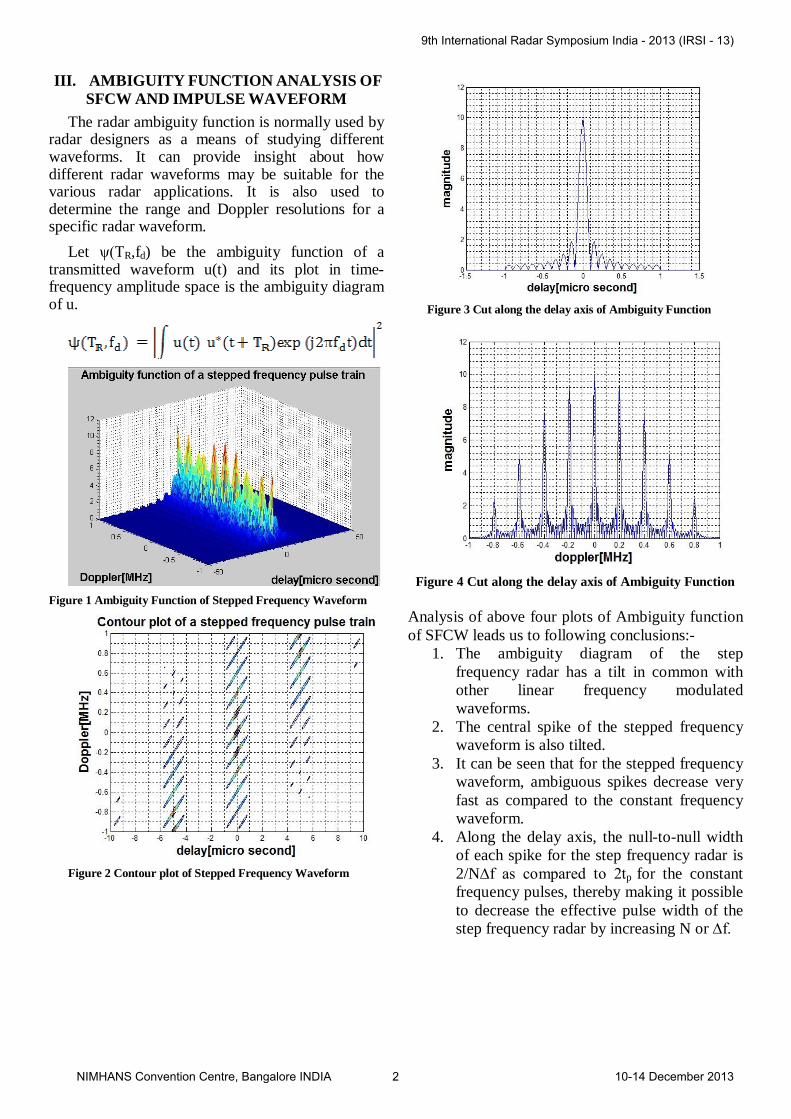
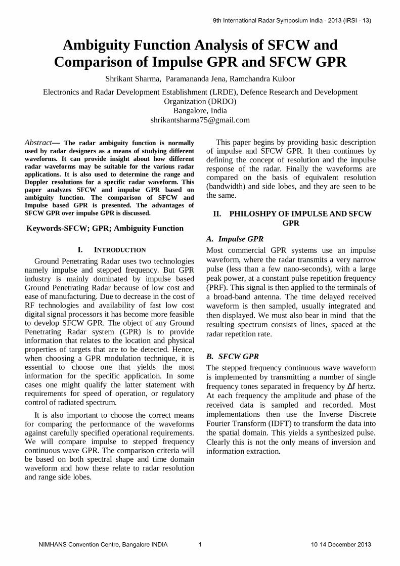
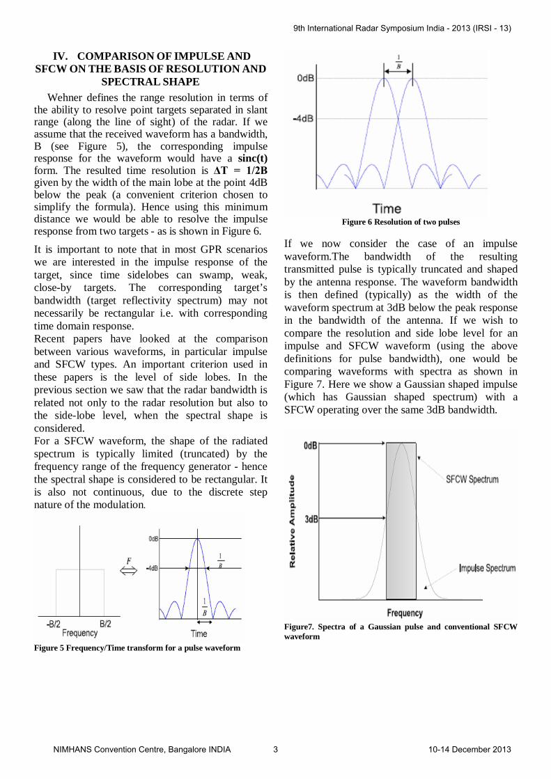
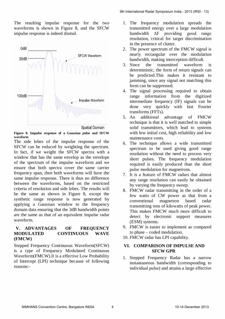
III. AMBIGUITY FUNCTION ANALYSIS OF SFCW AND IMPULSE WAVEFORM
The radar ambiguity function is normally used by radar designers as a means of studying different waveforms. It can provide insight about how different radar waveforms may be suitable for the various radar applications. It is also used to determine the range and Doppler resolutions for a specific radar waveform.
Let ψ(TR,fd) be the ambiguity function of a transmitted waveform u(t) and its plot in time-frequency amplitude space is the ambiguity diagram of u.
Figure 1 Ambiguity Function of Stepped Frequency Waveform
Figure 2 Contour plot of Stepped Frequency Waveform
Figure 3 Cut along the delay axis of Ambiguity Function
Figure 4 Cut along the delay axis of Ambiguity Function
Analysis of above four plots of Ambiguity function of SFCW leads us to following conclusions:-
1. The ambiguity diagram of the step frequency radar has a tilt in common with other linear frequency modulated waveforms.
2. The central spike of the stepped frequency waveform is also tilted.
3. It can be seen that for the stepped frequency waveform, ambiguous spikes decrease very fast as compared to the constant frequency waveform.
4. Along the delay axis, the null-to-null width of each spike for the step frequency radar is 2/N∆f as compared to 2tp for the constant frequency pulses, thereby making it possible to decrease the effective pulse width of the step frequency radar by increasing N or ∆f.
9th International Radar Symposium India - 2013 (IRSI - 13)
NIMHANS Convention Centre, Bangalore INDIA 2 10-14 December 2013
IV. COMPARISON OF IMPULSE AND SFCW ON THE BASIS OF RESOLUTION AND
SPECTRAL SHAPE Wehner defines the range resolution in terms of
the ability to resolve point targets separated in slant range (along the line of sight) of the radar. If we assume that the received waveform has a bandwidth, B (see Figure 5), the corresponding impulse response for the waveform would have a sinc(t) form. The resulted time resolution is ΔT = 1/2B given by the width of the main lobe at the point 4dB below the peak (a convenient criterion chosen to simplify the formula). Hence using this minimum distance we would be able to resolve the impulse response from two targets - as is shown in Figure 6. It is important to note that in most GPR scenarios we are interested in the impulse response of the target, since time sidelobes can swamp, weak, close-by targets. The corresponding target’s bandwidth (target reflectivity spectrum) may not necessarily be rectangular i.e. with corresponding time domain response. Recent papers have looked at the comparison between various waveforms, in particular impulse and SFCW types. An important criterion used in these papers is the level of side lobes. In the previous section we saw that the radar bandwidth is related not only to the radar resolution but also to the side-lobe level, when the spectral shape is considered. For a SFCW waveform, the shape of the radiated spectrum is typically limited (truncated) by the frequency range of the frequency generator - hence the spectral shape is considered to be rectangular. It is also not continuous, due to the discrete step nature of the modulation.
Figure 5 Frequency/Time transform for a pulse waveform
Figure 6 Resolution of two pulses
If we now consider the case of an impulse waveform.The bandwidth of the resulting transmitted pulse is typically truncated and shaped by the antenna response. The waveform bandwidth is then defined (typically) as the width of the waveform spectrum at 3dB below the peak response in the bandwidth of the antenna. If we wish to compare the resolution and side lobe level for an impulse and SFCW waveform (using the above definitions for pulse bandwidth), one would be comparing waveforms with spectra as shown in Figure 7. Here we show a Gaussian shaped impulse (which has Gaussian shaped spectrum) with a SFCW operating over the same 3dB bandwidth.
Figure7. Spectra of a Gaussian pulse and conventional SFCW waveform
9th International Radar Symposium India - 2013 (IRSI - 13)
NIMHANS Convention Centre, Bangalore INDIA 3 10-14 December 2013
The resulting impulse response for the two waveforms is shown in Figure 8, and the SFCW impulse response is indeed dismal.
Figure 8. Impulse response of a Gaussian pulse and SFCW waveform The side lobes of the impulse response of the SFCW can be reduced by weighting the spectrum. In fact, if we weight the SFCW spectra with a window that has the same envelop as the envelope of the spectrum of the impulse waveform and we ensure that both spectra cover the same carrier frequency span, then both waveforms will have the same impulse response. There is thus no difference between the waveforms, based on the restricted criteria of resolution and side lobes. The results will be the same as shown in Figure 8, except the synthetic range response is now generated by applying a Gaussian window to the frequency domain data ensuring that the 3dB bandwidth points are the same as that of an equivalent impulse radar waveform.
V. ADVANTAGES OF FREQUENCY MODULATED CONTINUOUS WAVE (FMCW) Stepped Frequency Continuous Waveform(SFCW) is a type of Frequency Modulated Continuous Waveform(FMCW).It is a effective Low Probability of Intercept (LPI) technique because of following reasons:-
1. The frequency modulation spreads the transmitted energy over a large modulation bandwidth ∆F providing good range resolution, critical for target discrimination in the presence of clutter.
2. The power spectrum of the FMCW signal is nearly rectangular over the modulation bandwidth, making interception difficult.
3. Since the transmitted waveform is deterministic, the form of return signals can be predicted.This makes it resistant to jamming, since any signal not matching this form can be suppressed.
4. The signal processing required to obtain range information from the digitized intermediate frequency (IF) signals can be done very quickly with fast Fourier transforms (FFTs).
5. An additional advantage of FMCW technique is that it is well matched to simple solid transmitters, which lead to systems with low initial cost, high reliability and low maintenance costs.
6. The technique allows a wide transmitted spectrum to be used giving good range resolution without the need to process very short pulses. The frequency modulation required is easily produced than the short pulse modulation for magnetrons.
7. It is a feature of FMCW radars that almost any range resolution can easily be obtained by varying the frequency sweep.
8. FMCW radar transmitting in the order of a few watts of CW power as that from a conventional magnetron based radar transmitting tens of kilowatts of peak power. This makes FMCW much more difficult to detect by electronic support measures (ESM) systems.
9. FMCW is easier to implement as compared to phase – coded modulation.
10. FMCW radar has LPI capability.
VI. COMPARISON OF IMPULSE AND SFCW GPR
1. Stepped Frequency Radar has a narrow instantaneous bandwidth (corresponding to individual pulse) and attains a large effective
9th International Radar Symposium India - 2013 (IRSI - 13)
NIMHANS Convention Centre, Bangalore INDIA 4 10-14 December 2013
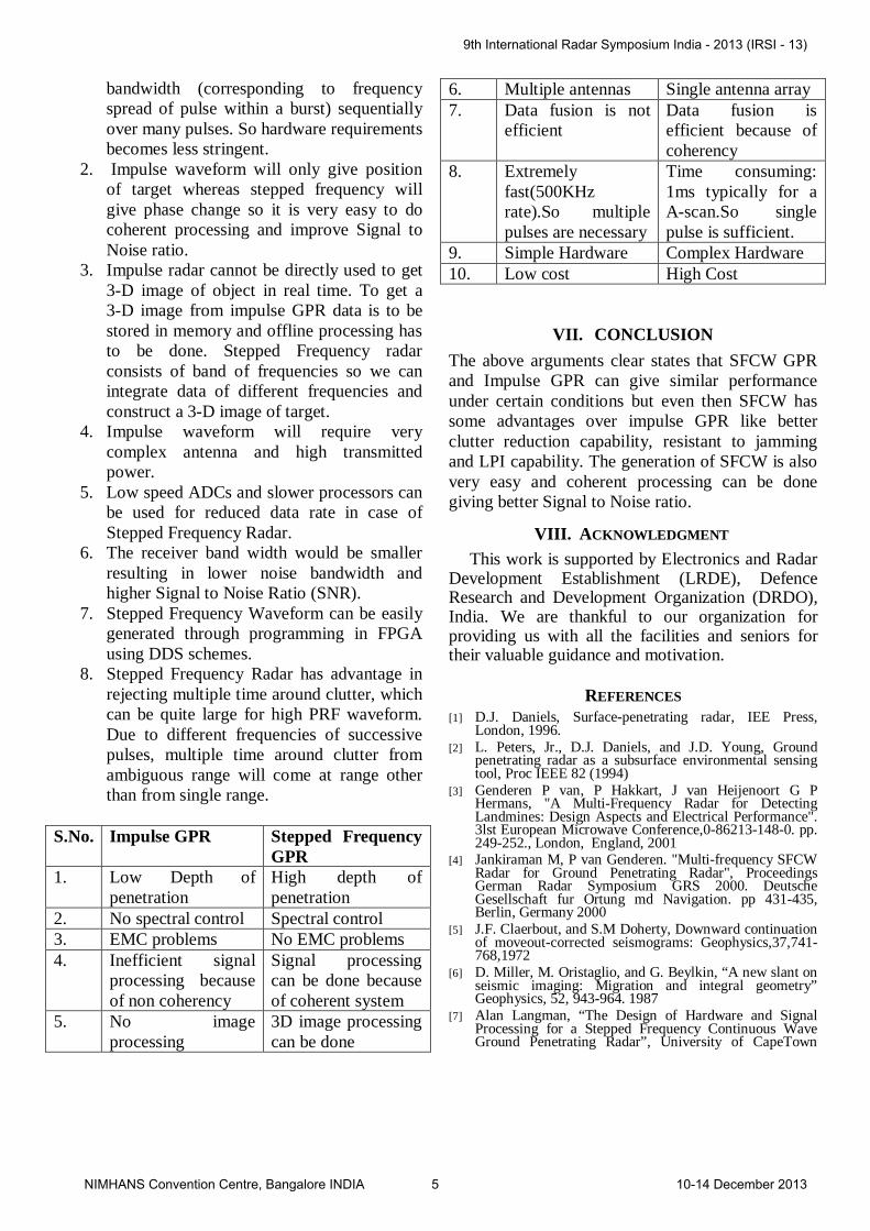
bandwidth (corresponding to frequency spread of pulse within a burst) sequentially over many pulses. So hardware requirements becomes less stringent.
2. Impulse waveform will only give position of target whereas stepped frequency will give phase change so it is very easy to do coherent processing and improve Signal to Noise ratio.
3. Impulse radar cannot be directly used to get 3-D image of object in real time. To get a 3-D image from impulse GPR data is to be stored in memory and offline processing has to be done. Stepped Frequency radar consists of band of frequencies so we can integrate data of different frequencies and construct a 3-D image of target.
4. Impulse waveform will require very complex antenna and high transmitted power.
5. Low speed ADCs and slower processors can be used for reduced data rate in case of Stepped Frequency Radar.
6. The receiver band width would be smaller resulting in lower noise bandwidth and higher Signal to Noise Ratio (SNR).
7. Stepped Frequency Waveform can be easily generated through programming in FPGA using DDS schemes.
8. Stepped Frequency Radar has advantage in rejecting multiple time around clutter, which can be quite large for high PRF waveform. Due to different frequencies of successive pulses, multiple time around clutter from ambiguous range will come at range other than from single range.
S.No. Impulse GPR Stepped Frequency GPR
1. Low Depth of penetration
High depth of penetration
2. No spectral control Spectral control 3. EMC problems No EMC problems 4. Inefficient signal
processing because of non coherency
Signal processing can be done because of coherent system
5. No image processing
3D image processing can be done
6. Multiple antennas Single antenna array 7. Data fusion is not
efficient Data fusion is efficient because of coherency
8. Extremely fast(500KHz rate).So multiple pulses are necessary
Time consuming: 1ms typically for a A-scan.So single pulse is sufficient.
9. Simple Hardware Complex Hardware 10. Low cost High Cost
VII. CONCLUSION The above arguments clear states that SFCW GPR and Impulse GPR can give similar performance under certain conditions but even then SFCW has some advantages over impulse GPR like better clutter reduction capability, resistant to jamming and LPI capability. The generation of SFCW is also very easy and coherent processing can be done giving better Signal to Noise ratio.
VIII. ACKNOWLEDGMENT
This work is supported by Electronics and Radar Development Establishment (LRDE), Defence Research and Development Organization (DRDO), India. We are thankful to our organization for providing us with all the facilities and seniors for their valuable guidance and motivation.
REFERENCES [1] D.J. Daniels, Surface-penetrating radar, IEE Press,
London, 1996. [2] L. Peters, Jr., D.J. Daniels, and J.D. Young, Ground
penetrating radar as a subsurface environmental sensing tool, Proc IEEE 82 (1994)
[3] Genderen P van, P Hakkart, J van Heijenoort G P Hermans, "A Multi-Frequency Radar for Detecting Landmines: Design Aspects and Electrical Performance". 3lst European Microwave Conference,0-86213-148-0. pp. 249-252., London, England, 2001
[4] Jankiraman M, P van Genderen. "Multi-frequency SFCW Radar for Ground Penetrating Radar", Proceedings German Radar Symposium GRS 2000. Deutsche Gesellschaft fur Ortung md Navigation. pp 431-435, Berlin, Germany 2000
[5] J.F. Claerbout, and S.M Doherty, Downward continuation of moveout-corrected seismograms: Geophysics,37,741-768,1972
[6] D. Miller, M. Oristaglio, and G. Beylkin, “A new slant on seismic imaging: Migration and integral geometry” Geophysics, 52, 943-964. 1987
[7] Alan Langman, “The Design of Hardware and Signal Processing for a Stepped Frequency Continuous Wave Ground Penetrating Radar”, University of CapeTown
9th International Radar Symposium India - 2013 (IRSI - 13)
NIMHANS Convention Centre, Bangalore INDIA 5 10-14 December 2013
BIO DATA OF AUTHOR
Shrikant Sharma obtained his BE from Government Engineering College, Jabalpur, India in 2007. He has worked as Software Engineer from the year 2007 to 2009 in Zensar
Technologies. He has joined DRDO as Scientist – ‘B’ in 2009 and posted to LRDE. He has been promoted to Scientist – ‘C’ in the year 2012. He has simulated and implemented Signal Processing module of Handheld & Vehicle mounted Ground Penetrating Radar. He is also involved in System Design and System Calculations for Handheld & Vehicle mounted Ground Penetrating Radar. He has published four research papers in IEEE conferences. His research interests include ultra wideband signal processing and electromagnetics.
9th International Radar Symposium India - 2013 (IRSI - 13)
NIMHANS Convention Centre, Bangalore INDIA 6 10-14 December 2013


![MIMO Radar Ambiguity Optimization Using Frequency-Hopping ... · In a SIMO radar system, the radar ambiguity function is defined as [8] JX(T)v J u(t)u*(t+T)eJ2 vtdt (1) where u(t)](https://img.pdfslide.net/doc/110x75/5ead46494f556477e90d9f10/mimo-radar-ambiguity-optimization-using-frequency-hopping-in-a-simo-radar-system.jpg)