Embed Size (px)
Citation preview

Licence L8889/2015/1 IR-T08 Amendment Notice (Major) template v2.0 (July 2017) 1
Licence Number L8889/2015/1
Licence Holder Eastern Metropolitan Regional Council
File Number: DER2015/000777
Premises Red Hill Waste Management Facility
Lot 11 on Diagram 69105, Lot 2 on Diagram 68630 and Lot 1 on Diagram 15239 Toodyay Road, Red Hill and Lot 12 on Plan 26468 Toodyay Road, Gidgegannup.
Date of Amendment 09 July 2018
Amendment
The Chief Executive Officer (CEO) of the Department of Water and Environmental Regulation (DWER) has amended the above Licence in accordance with section 59 of the Environmental Protection Act 1986 as set out in this Amendment Notice. This Amendment Notice constitutes written notice of the amendment in accordance with section 59B(9) of the EP Act.
Date signed: 9 July 2018
Manager Waste Industries Regulatory Services (Environment)
an officer delegated under section 20 of the Environmental Protection Act 1986 (WA)
Amendment Notice 3

Licence L8889/2015/1 IR-T08 Amendment Notice (Major) template v2.0 (July 2017) 2
Definitions and interpretation
Definitions
In this Amendment Notice, the terms in Table 1 have the meanings defined.
Table 1: Definitions
Term Definition
AER Annual Environment Report
Application Licence amendment application submitted by EMRC on the 14 November 2017 seeking Part V approval to construct and operate three (3) leachate ponds (one holding pond and two evaporation ponds) to manage excess leachate currently being stored in the decommissioned Class IV cell. Ultimately these ponds will be used to store and manage all other existing and future leachate generated from Class III landfill cells at the site in a centralised system.
The information provided as part of the Application is documented in Table 2.
Category/ Categories/ Cat.
categories of Prescribed Premises as set out in Schedule 1 of the EP Regulations
CEO means Chief Executive Officer.
CEO for the purposes of notification means:
Director General Department Administering the Environmental Protection Act 1986 Locked Bag 33 Cloisters Square PERTH WA 6850 [email protected]
CS Act Contaminated Sites Act 2003 (WA)
Delegated Officer an officer under section 20 of the EP Act
DWER Department of Water and Environmental Regulation
EMRC Eastern Metropolitan Regional Council
EPA Environmental Protection Authority
EP Act Environmental Protection Act 1986 (WA)
EP Regulations Environmental Protection Regulations 1987 (WA)
Existing Licence The Licence issued under Part V, Division 3 of the EP Act and in force prior to the commencement of and during this Review

Licence L8889/2015/1 IR-T08 Amendment Notice (Major) template v2.0 (July 2017) 3
Hydraulic conductivity A property or measurement that describes the flow of a liquid (usually water) through pore spaces or fractures, per unit of energy gradient
Licence Holder / Licensee
Eastern Metropolitan Regional Council
MS Ministerial Statement
Occupier has the same meaning given to that term under the EP Act.
Prescribed Premises has the same meaning given to that term under the EP Act.
Premises refers to the Premises to which this Amendment Notice applies, as specified at the front of this Notice.
Risk Event as described in Guidance Statement: Risk Assessment
Works refers to the Works specified in this Amendment Notice to be carried out at the Premises.
Amendment Notice
This amendment is made pursuant to section 59 of the Environmental Protection Act 1986 (EP Act) to amend the Exiting Licence L8889/2015/1 issued under the EP Act for a prescribed Premises as set out below. This notice of amendment is given under section 59B(9) of the EP Act.
This notice is limited only to an amendment for Category 64 and 65 in relation to the proposed construction and operation of three (3) leachate ponds (1 holding pond and 2 evaporation ponds). No changes to the aspects of the Existing Licence relating to Category 12, 62 and 627A have been requested by the Licensee.
The following guidance statements have informed the decision made on this amendment
Guidance Statement: Regulatory Principles (July 2015);
Guidance Statement: Decision Making (February 2017);
Guidance Statement: Risk Assessment (February 2017);
Guidance Statement: Land Use Planning (February 2017);
Guidance Statement: Environmental Siting (November 2016); and
Guidance Statement: Setting Conditions (October 2015).
Application details
On 14 November 2017 the Eastern Metropolitan Regional Council (EMRC) submitted an Application to the Department of Water and Environmental Regulation (DWER) to amend Licence L8889/2015/1 for the Red Hill Waste Management Facility (Red Hill WMF).
The scope of the application relates to the proposed construction and operation of three (3) leachate ponds (one holding pond and two evaporation ponds) to manage excess leachate currently being stored in the decommissioned Class IV cell.

Licence L8889/2015/1 IR-T08 Amendment Notice (Major) template v2.0 (July 2017) 4
During the validation of the Application (pre-acceptance) the Delegated Officer determined that further information was required to allow DWER to complete risk-based assessment. EMRC was formally requested to provide additional information on 1 December 2017; EMRC provided the requested information to DWER on 22 December 2017 and 15 January 2018. Additional clarification on technical aspects was also requested as part of the assessment process.
Table 2 lists the documents and information provided with the Application and that were submitted during the assessment process.
Documents and information submitted as part of the Application
Document/information description Date received
1 Licence Application Form (EMRC,14 November 2017) The following attachments were included with the Application Form:
Attachment 2 – Maps; and
Attachment 3A – Technical Specification Red Hill Waste Management Facility – Leachate Pond Construction (October 2017, Talis).
Amendment Fee Calculator (Excel spreadsheet )
14 November 2017
2 EMRC Response to Information Request (EMRC, 22 December 2017) The following attachments were included with in the EMRC response:
Attachment 1 – Letter Report: Design Principles of Evaporation Ponds at Red Hill Waste Management Facility (Talis, 22 December 2017);
Attachment 2 – Aspects and Impacts Register (EMRC, Undated – Document No. 00000-ENV-PL-001) ;
Attachment 3 – Letter correspondence dated 7 December 2017 between Kott Gunning Lawyers and EMRC providing legal opinion on development approval requirements under the Planning and Development Act 2005 for the installation of leachate ponds;
Attachment 4 – Letter correspondence dated 8 December 2017 between EMRC and the City of Swan regarding development approval requirements;
Attachment 5 – Email correspondence dated 15 December 2017 between EMRC and the City of Swan in relation to consultation on the proposal; and
Attachment 6 – Site Plan depicting groundwater, surface water, and leachate monitoring locations (EMRC, 6 November 2017).
22 December 2017.
3 Additional technical information in response to DWER information request dated 1 December 2017: Letter Report: Stability Assessment of Evaporation Ponds at Red Hill Waste Management Facility (Talis, 11 January 2018).
15 January 2018
4 Email correspondence dated 15 February 2017 between EMRC and DWER providing clarification on the use on Factors of Safety (FoS) in the Stability Assessment.
15 February 2018
5 Email correspondence dated 1 May 2018 from ERMC to DWER confirming hydraulic conductivity performance of proposed liner components for leachate ponds
1 May 2018
Amendment description
(EMRC) (Licensee) proposes to construct and operate three (3) leachate ponds (one holding pond and two evaporation ponds) to manage excess leachate currently being stored in the decommissioned Class IV cell.
Initially the ponds will be used to manage approximately 50,000-60,000 m3 of leachate currently being stored in the decommissioned Class IV cell. Once all the leachate has been successfully removed from the decommissioned Class IV cell, the proposed leachate ponds

Licence L8889/2015/1 IR-T08 Amendment Notice (Major) template v2.0 (July 2017) 5
would then be used to manage all other existing and future leachate generated from Class III (or lower) landfills at the site in a centralised leachate management system. The Class IV cell would then be recommissioned to be an operational Class IV landfill cell.
The leachate ponds are proposed to be constructed on the south-eastern corner of the site within Lot 12 on Plan 26468 Toodyay Road, Gidgegannup; being the most eastern Lot of the Prescribed Premises (refer to Figure 1, Attachment 1). The proposed footprint is currently used to stockpile clay fill materials.
Scope of works for construction The proposed scope of works as outlined in the Application is limited to the following:
General earthworks to create voids for new leachate ponds (one Holding Pond and two Evaporation Ponds);
Installation of 500mm thick Engineered Clay Layer across the base and side slopes;
Installation of the geosynthetic lining system across the base and side slopes:
o Geosynthetic Clay Liner (GCL); and
o 2mm High Density Polyethylene (HDPE) Double Textured Geomembrane;
Leak detection survey following the installation of the geomembrane;
Installation of safety netting on the interior face of the evaporation ponds; and
Construction and installation of surface water management infrastructure and fencing.
The Licensee is not proposing any changes to the design or throughput capacity of the existing landfill cells from which leachate is generated.
Key personnel or parties involved in the project
A summary of key personnel or parties involved in delivering the project is outlined below (sourced from Technical Specification (October 2017, Talis)):
Superintendent – acting on-behalf of the Principal, will serve as a single point of contact for the design engineer, Contractor and CQA consultant;
Design Engineer – provides design engineering services for earthworks. Any proposed changes during construction is to be signed off by the Design Engineer;
CQA Consultant – is an independent party not affiliated with the contractor, subcontractors, suppliers or manufacturers. The CQA consultant may be the design engineer. Has the overall responsibility for managing, coordinating and implementing the CQA activities and confirming that the Contractor’s construction quality control activities are performed in accordance with the CQA Plan, construction drawings and technical specifications.
Contractor – is responsible for the timely construction of the project, as delineated in the design drawings and technical specifications and in accordance with the CQA Plan;
Resin Supplier – produces and delivers the resin to the geosynthetics manufacturer
Geosynthetics Manufacturer – responsible for the production of finished material from appropriate raw materials. The geosynthetic manufacturer reports to the geosynthetics installer
Geosynthetics Installer – responsible for field handling, storage, placement, seaming, loading or anchoring against wind uplift and other aspects of the geosynthetic material installation; and
Materials Testing Laboratory – CQA consultant may engage a materials testing
Licence L8889/2015/1 IR-T08 Amendment Notice (Major) template v2.0 (July 2017) 6
laboratory independent form the Contractor, subcontractors, or any material supplier or manufacturer. The laboratory may conduct tests on representative samples to evaluate their properties and compliance with the technical specifications.
Pond design specifications
Pond sizing
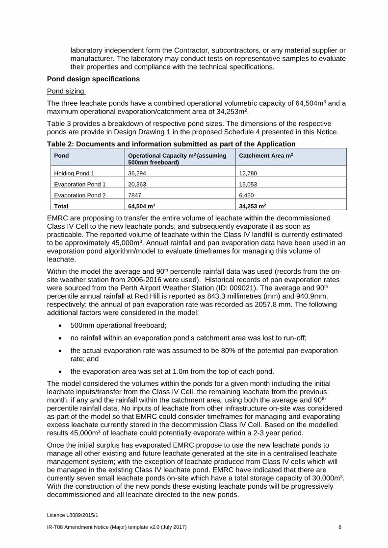
The three leachate ponds have a combined operational volumetric capacity of 64,504m3 and a maximum operational evaporation/catchment area of 34,253m2.
Table 3 provides a breakdown of respective pond sizes. The dimensions of the respective ponds are provide in Design Drawing 1 in the proposed Schedule 4 presented in this Notice.
Table 2: Documents and information submitted as part of the Application
Pond Operational Capacity m3 (assuming 500mm freeboard)
Catchment Area m2
Holding Pond 1 36,294 12,780
Evaporation Pond 1 20,363 15,053
Evaporation Pond 2 7847 6,420
Total 64,504 m3 34,253 m2
EMRC are proposing to transfer the entire volume of leachate within the decommissioned Class IV Cell to the new leachate ponds, and subsequently evaporate it as soon as practicable. The reported volume of leachate within the Class IV landfill is currently estimated to be approximately 45,000m3. Annual rainfall and pan evaporation data have been used in an evaporation pond algorithm/model to evaluate timeframes for managing this volume of leachate.
Within the model the average and 90th percentile rainfall data was used (records from the on-site weather station from 2006-2016 were used). Historical records of pan evaporation rates were sourced from the Perth Airport Weather Station (ID: 009021). The average and 90th percentile annual rainfall at Red Hill is reported as 843.3 millimetres (mm) and 940.9mm, respectively; the annual of pan evaporation rate was recorded as 2057.8 mm. The following additional factors were considered in the model:
500mm operational freeboard;
no rainfall within an evaporation pond’s catchment area was lost to run-off;
the actual evaporation rate was assumed to be 80% of the potential pan evaporation rate; and
the evaporation area was set at 1.0m from the top of each pond.
The model considered the volumes within the ponds for a given month including the initial leachate inputs/transfer from the Class IV Cell, the remaining leachate from the previous month, if any and the rainfall within the catchment area, using both the average and 90th percentile rainfall data. No inputs of leachate from other infrastructure on-site was considered as part of the model so that EMRC could consider timeframes for managing and evaporating excess leachate currently stored in the decommission Class IV Cell. Based on the modelled results 45,000m3 of leachate could potentially evaporate within a 2-3 year period.
Once the initial surplus has evaporated EMRC propose to use the new leachate ponds to manage all other existing and future leachate generated at the site in a centralised leachate management system; with the exception of leachate produced from Class IV cells which will be managed in the existing Class IV leachate pond. EMRC have indicated that there are currently seven small leachate ponds on-site which have a total storage capacity of 30,000m3. With the construction of the new ponds these existing leachate ponds will be progressively decommissioned and all leachate directed to the new ponds.

Licence L8889/2015/1 IR-T08 Amendment Notice (Major) template v2.0 (July 2017) 7
EMRC have indicated that the volume of leachate generated at Red Hill has been estimated using historic climate data and the Hydrologic Evaluation of Landfill Performance (HELP) model. Based on the modelling results, a leachate volume of 4,000 – 7,000m3 is estimated to be generated from the capped and uncapped landfill areas on-site. This is a much smaller volume than that modelled above therefore sufficient capacity will be available in the new leachate ponds.
Stability assessment
EMRC commissioned a stability assessment (Talis, 11 January 2018) to be undertaken in support of the proposal; a summary of the assessment is provided below:
Source: Stability Assessment of Evaporation Ponds at Red Hill Waste Management Facility (Talis 11 January 2018); and additional clarification from EMRC/Talis provided to DWER on 15 February (via email) regarding the use of Factors of Safety (FoS) in the Stability Assessment.
The stability analysis program SLIDE 7.030 from RocScience was used to analyse the sections using the Bishop simplified and Morgenstern-Price forms of analysis;
The cross section ‘XSECT B’ (refer to Schedule 4 of proposed amendments in this notice – Design Drawing 1) has been analysed in its two component parts, the southern outer embankment and the northern embankment and cut slope;
The sections were analysed under non-operational conditions, operational conditions (pond full) and operational conditions with pseudo-static seismic loading. The pseudo-static seismic return periods considered were:
1:500 - Operating Base Earthquake (OBE)
1:1000 - Maximum Design Earthquake (MDE)
1:2000 - Maximum Credible Earthquake (MCE)
For the limit state equilibrium analyses, a factor of safety of ≥1.3 is considered appropriate when using peak shear strength parameters under static loading. A factor of safety of ≥1.1 under earthquake loading for an operating base earthquake, and a factor of safety of ≥1.0 for a maximum design earthquake and maximum credible earthquake;
Calculated factors for safety under static loading ranged from 1.760 to 2.599, and therefore in excess of the minimum acceptable value of 1.3, and are considered acceptable;
Calculated factors for safety under OBE pseudo-static loading ranged from 1.594 to 1.725, and therefore in excess of the minimum acceptable value of 1.1, and are considered acceptable;
Calculated factors for safety under MDE pseudo-static loading ranged from 1.462 to 1.586, and therefore in excess of the minimum acceptable value of 1.1, and are considered acceptable.
Calculated factors for safety under MCE pseudo-static loading ranged from 1.162 to 1.270, and therefore in excess of the minimum acceptable value of 1.0, and are considered acceptable
It was also noted that the leachate ponds are not considered to be permanent features within the landform, and will be subsequently decommissioned during the post-closure period of the site when they are no longer required.
Liner design specifications

Licence L8889/2015/1 IR-T08 Amendment Notice (Major) template v2.0 (July 2017) 8
The liner for each pond is to consist of the following configuration:
500mm thick Engineered Clay Attenuation Layer – based on characterisation test results, the clay material to be used exhibits a hydraulic conductivity ranging from 6.449 x 10⁻⁹ m/s to 8.531 x 10⁻⁹ m/s;
Geosynthetic Clay Liner (GCL) – hydraulic conductivity of ≤ 2.5 x 10⁻¹¹ m/s; and
2mm High Density Polyethylene (HDPE) Double Textured Geomembrane – the hydraulic conductivity of a HDPE liner is typically in the order of 1 x 10-14 to 1 x 10-15 m/s
The General Arrangement Plan for the proposed leachate ponds is provided in Design Drawing 1 (refer to the proposed Schedule 4 in this notice). The anchor trench and lining detail is presented in Design Drawing 1 (refer to Schedule 4 in this notice).
Water level measurements from eight (8) on-site monitoring bores (average wet season groundwater levels based on the June-October monitoring data 2012-2017) were used to estimate separation distances between groundwater and the lowest base elevation of the leachate ponds. Based on these records, groundwater levels have been estimated to be greater than 6.4m below the base elevation in all three ponds. The estimated separation distances are shown in cross sections in Design Drawing 3 and 4 (refer to Schedule 4 in this notice). Design Drawing 2 shows the respective transects for each sections depicted in Design Drawing 3 and 4.
A leak detection survey is proposed to be carried out following installation of the geomembrane with the exposed surface being surveyed using a water lance or arc testing method. All detected anomalies will be investigated and repaired, where required. Following repair, the local area will be resurveyed to verify repair work and ensure the defect was not masking further defects. Leak detection survey results are to be reported in the certification report as outlined below.
Construction Quality Assurance Plan
A Construction Quality Assurance (CQA) Plan has been provided in the Application (as part of the Technical Specification (October 2017, Talis)). The CQA Plan details the testing methods and quality assurance procedures to supply and install leachate ponds at the site with specific regard to the scope of works as outlined above.
At the completion of the work, the CQA consultant is to submit to the Superintendent a signed final certification report. The report will document that work has been performed in compliance with the construction documents (Technical Specification (October 2017, Talis)) and will outline that physical sampling and testing has been conducted at the appropriate frequencies specified in the CQA Plan and the required CQA documentation has been completed. As built drawings will also form part of the certification report.
Critical hold points for completed works are listed in Section 2.6 of the Technical Specification (October 2017, Talis) which requires the Superintendent and/or the CQA Consultant to check and sign-off before subsequent works can commence – these hold points are summarised in Table 3 below:
Table 3: Construction hold points
Hold Point Number Item Reference in Technical Specification (October 2017, Talis)
1 Approval of Traffic Management Plan Section 2.13
2 Approval of Formation Surface Section 4.5.8
3 Approval of Engineered Clay Attenuation Layer Field Trial
Section 4.7.2.1
4 Approval of Engineered Clay Section 4.7.3

Licence L8889/2015/1 IR-T08 Amendment Notice (Major) template v2.0 (July 2017) 9
Hold Point Number Item Reference in Technical Specification (October 2017, Talis)
Attenuation Layer Testing
5 Approval of Engineered Clay Attenuation Layer Installed Thickness
Section 4.7.5
6 Approval of Engineered Clay Attenuation Surface
Section 6.4.1
7 Approval of GCL Conformance Testing Section 6.5.2
8 Approval of GCL Installation Section 6.5.3
9 Approval of HDPE Conformance Testing
Section 6.5.7
10 Approval of HDPE Non-destructive Testing
Section 6.5.10.1
11 Approval of HDPE Destructive Testing Section 6.5.10.2
Section 6.5.10.2
12 Approval of Leak Detection Testing Section 7
Operational aspects
Transfer of leachate
EMRC proposes to install a C220 Transfer Pump to transfer all the leachate from the decommissioned Class IV cell to the new leachate ponds. To convey leachate, PN 10/160mm pipe will be installed with joints electrofusion welded.
Smaller transfer pumps will be permanently positioned within respective ponds to transfer leachate between the holding pond and the two evaporation ponds to keep levels at an ideal level for optimum evaporation.
Assisted evaporation
The existing assisted evaporation currently operating at the Class IV cell was originally proposed to be relocated along with the generator and control station as part of the Application.
DWER understands that a mechanical evaporator was installed and fully commissioned within the Class IV cell in April 2015 (EMRC, March 2016 - Red Hill Annual Monitoring & Compliance Report 2015). The installation of this equipment was not approved by the Department at the time.
On 19 June 2018, EMRC advised DWER to remove this component from the Application as EMRC was gathering further technical information relating to the activity and would seek approval separately (see additional information in Appendix 2).
Operational freeboard
The leachate levels in all ponds are to be monitored daily and a 500mm freeboard maintained at all times. Pumping infrastructure is in place to relocate leachate to other ponds should this be required to maintain the 500mm freeboard.
Stormwater management/diversions measures
Stormwater diversion drains will be installed around the perimeter of the proposed leachate ponds cell and all drains will be kept clear of any waste to ensure clear drainage and reduce the risk of contamination. Diverted stormwater will be directed to on-site stormwater storage ponds where sediment and nutrients are given a chance to settle. Diversion drains and associated storage ponds are depicted in Attachment 1 (Figure 2).

Licence L8889/2015/1 IR-T08 Amendment Notice (Major) template v2.0 (July 2017) 10
Surface water and groundwater monitoring program
Red Hill Waste Management Facility is located on the divide of three surface water catchments; Christmas Tree Creek which enters Jane Brook, Susannah Brook and Strelley Brook. The proposed leachate ponds lie within the surface water catchment of Christmas Tree Creek with groundwater flowing in a southerly to south-westerly direction.
A network of monitoring bores already exists in close proximity to the perimeter of the proposed leachate ponds. This network consists of monitoring bores SP43S, FMB1 and FMB3 which are located cross to up-hydraulic gradient of the proposed leachate ponds and will provide background levels to monitor down-hydraulic gradient contaminant levels against. Monitoring bores SP4D, SP36D, SP37D, SP42D and SP46D are located down-hydraulic gradient from the proposed leachate ponds. EMRC have indicated that water quality results will be compared to historical data to determine any potential discharge of leachate constituents from the leachate ponds.
A map of the current groundwater, surface water and leachate monitoring points is provided in Attachment 1 (Figure 3).
DWER notes that the Existing Licence does not currently include requirements to monitor surface water or groundwater. As outlined in the Section ‘Legislative context – Part IV of the EP Act’ (in this Notice – see below) the Premises is currently subject to several Ministerial Statements (MS) under Part IV of the EP Act, of which there are requirements relating to surface water and groundwater management and monitoring for the site.
In accordance with Ministerial Statement requirements groundwater at the Premises is currently monitored on a quarterly basis and analysed for a range or inorganic and organic parameters. Information provided in a previous amendment application (refer to Amendment Notice 1 dated 6 September 2017) indicates that there are currently 47 bores that are monitored around the facility. EMRC has historically provided a summary of the results obtained from these ongoing monitoring programs within the annual monitoring reports provided in accordance with condition G3 of the Existing Licence.
Legislative context – Part IV of the EP Act
The Premises is currently subject to three Ministerial Statements (MS) under Part IV of the EP Act. In regulating the Premises under Part V, Division 3 of EP Act, DWER will seek to avoid duplication of requirements imposed under Part IV. Pursuant to section 59B(7) of the EP Act, DWER will also not amend a Part V licence to be contrary to, or otherwise than in accordance with, an implementation agreement or decision.
A summary of the respective Ministerial Statements is provided below:
MS 274 (15 July 1992) – Relates to the Red Hill Waste Management Facility Extension;
MS 462 (21 November 1997) – Relates to the establishment of Class IV waste disposal cells at the existing Red Hill Waste Management Facility; and
MS 976 (9 July 2014) – Relates to the proposal to construct and operate a resource recovery facility within the existing Red Hill Waste Management Facility, for the processing of waste to produce energy, using either anaerobic digestion or gasification technology.
MS 274 and MS 462 are the main Statements that relate to the construction, operation and post closure management of waste handling and landfilling aspects at the Red Hill Waste Management Facility.
As part of the Part V assessment, on 29 November 2017 DWER referred the Application to EPA Services to advise whether changes where required to the existing MS under Part IV of

Licence L8889/2015/1 IR-T08 Amendment Notice (Major) template v2.0 (July 2017) 11
the EP Act.
EPA Services subsequently met with EMRC on 13 December 2017 regarding the proposal and to discuss whether approval under Part IV of the EP Act was required. Following this, on 4 January 2018, EPA Services advised EMRC that the proposed construction of the leachate ponds would be inconsistent with MS 274 and MS 462 and consequently approval under Part IV (section 45C) of the EP Act is required.
On 24 April 2018 EMRC submitted to DWER (EPA Services) a request to change a proposal under section 45c of the EP Act. The proposed changes only relate to MS 274.
On 26 June 2018 the EPA approved the proposed changes in relation to MS 274. EPA concluded that the changes were unlikely to result in a significant detrimental effect of the environment in addition to, or different from, the effect of the original proposal. The approved changes included:
the incorporation of part of Lot 12 of the Red Hill Waste Management Facility into the authorised extent of MS 274;
construction and operation of landfill cells within part of Lot 12 as per Licence L8889; and
to construct separately located leachate ponds on Lot 12 where:
o one area is used to store leachate generated from the greenwaste processing area; and
o one area is used to store leachate generated from Class III cells.
The leachate currently stored in the decommissioned Class IV cell is of a quality consistent with that derived from Class III landfills and therefore is suitable to be transferred into the new leachate ponds. Once the Class IV cell is operational, associated leachate will be managed within existing dedicated Class IV leachate ponds.
No other changes were made to conditions of MS 274.
Legislative context – Contaminated Sites Act 2003
The Premises is classified as ‘Contaminated - remediation required’ under the Contaminated Sites Act 2003. The reasons for classifications state that groundwater beneath the southern portion of the site has been impacted by landfill leachate and contains metals and nutrients.
Amendment history
Table 4 provides the amendment history for L8889/2015/1
Table 4: Licence amendments for L8889/2015/1
Instrument Issued Amendment
L8889/2015/1 17/03/2016 Construction of a green-waste processing hardstand pad and associated relocation of existing green-waste processing operations.
L8889/2015/1 06/09/2017 Amendment Notice 1 – approval to accept and bury PFAS contaminated solid waste in existing Class III landfill cells (Farm Stage 1 and 2 and Stage 15).
L8889/2015/1 01/05/2018 Amendment Notice 2 – approval to accept and store paint wastes and updates to landfill acceptance criteria for PFAS impacted solid wastes (Special Waste Type 3).
L8889/2015/1 DRAFT Amendment Notice 3 – construction and operation of three (3) leachate ponds (1 holding pond and 2 evaporation ponds) to manage excess leachate

Licence L8889/2015/1 IR-T08 Amendment Notice (Major) template v2.0 (July 2017) 12
currently being stored in the decommissioned Class IV cell. Ultimately these ponds will be used to store and manage all other existing and future leachate generated from Class III landfill cells at the site in a centralised system.
Location and receptors
The closest residential receptor to the proposed leachate ponds is located approximately 620m south and 850m east.
Table 5 provides a detailed summary on residential receptors and distances from activity boundaries within the Premises.
Table 5: Receptors and distance from activity boundary
Residential and sensitive Premises Distance from Prescribed Premises
Semi-rural residential areas and farms Immediately to north and north-east of the Premises; multiple Lots ranging from approximately 350m to 1.5km from Farm Stage 1/2 landfill operations (covered by works approval W4547/2009/1 and W5291/2012/1) and 1000m north north-west and north of the proposed leachate pond footprint.
Immediately to the east of the Premises (Lot 12); Barbarich Estate comprising of multiple Lots ranging approximately from 800m from Farm Stage 1/2 and 720m from the proposed leachate ponds.
To the south and south-east of the Premises; multiple Lots ranging from approximately 750m from Stage 15, 1.3km from Farm Stage 1/2 and 620m from the proposed leachate ponds. These Lots are separated from the Premises by a vegetation buffer (approx. 260m to 400m wide) located on Lot 82 on Diagram 18309 and Lot 501 on Plan 40105, Parkerville (owned by EMRC), followed by a drainage/public recreation reserve (approx. 50m-125m wide) on Lot 62 on Plan 23731 and Lot 15403 on Plan 40033, Parkerville (vested in the Shire of Mundaring).
Table 6 below lists the relevant environmental receptors in the vicinity of the Prescribed Premises which may be receptors relevant to the proposed amendment.
Table 6: Environmental receptors and distance from activity boundary
Environmental receptors Distance from Prescribed Premises
John Forrest National Park (bushland)
Lot 11664 on Plan 217947, Red Hill – Crown Reserve 7537
Located to the south and immediately adjacent to the boundary of Lot 11 and 2 of the Premises and approximately 650m to the south-west of the proposed leachate ponds.
Bushland
Lot 501 on Plan 40105, Parkerville
Lot 82 on Diagram 18309, Parkerville
Bushland is also located immediately adjacent to the boundary of Lot 1 and 12 of the Premises, and approximately 150m south of the proposed leachate ponds.
EMRC is the owner of the land.
Threatened / Priority Fauna – Mammals and Birds
Priority Fauna P4 (mammals) – mapped as being observed within Lot 1 of the Premises, in previously landfilled areas currently subject to rehabilitation. Fauna Survey date 29/10/2014
Priority Fauna P4 (mammals) – mapped as being observed within Lot 1 of the Premises, in previously landfilled areas currently subject to rehabilitation. Fauna Survey date 18/05/2012
Birds (Schedule 5 – Migratory birds protected under an international agreement); mapped as being observed within Lot 2 of the Premises, in previously landfilled areas currently subject to rehabilitation. Fauna Survey dates 29/10/2014 and 04/11/2015

Licence L8889/2015/1 IR-T08 Amendment Notice (Major) template v2.0 (July 2017) 13
Environmental receptors Distance from Prescribed Premises
Birds (Schedule 3 – Fauna that is rare or is likely to become extinct as vulnerable fauna); mapped as being observed within Lot 2 of the Premises, in previously landfilled areas currently subject to rehabilitation. Fauna Survey dates 29/10/2014 and 04/11/2015.
Designated Area – Surface Water Area
The entire Premises and surrounding land is mapped as proclaimed surface water area under the Rights in Water Irrigation Act 1914 named the “Swan River System”.
Susannah Brook (Significant Stream) Approximately 1km to the north of the Premises boundary, 1.2km from Farm Stage 1/2 Class III cells and 1.8km from the proposed leachate ponds.
Related drainage lines (classed as minor, perennial watercourses) also run north-south of Susannah Brook; the closest is located approximately 250m north of Farm Stage 1/2 and 920m north of the proposed leachate ponds, located within Lot 51 (1157) Toodyay Road, Gidgegannup.
Christmas Tree Creek (Watercourse - minor, perennial)
Approximately 370m to the south of the Premises boundary, 680m from the Stage 15 Class III cell and 450m south of the proposed leachate ponds. Christmas Tree Creek is a tributary of Jane Brook.
Table 7 summaries the geology and hydrogeological characteristics for the Premises (MSGM, July 2017 and Strategen Environmental Consultants Pty Ltd, June 2017).
Table 7: Geology and hydrogeology for the Premises
Environmental aspect Description
Geology The geology of the region is characteristic for that of the Yilgarn Craton, being dominated by granitic basement rocks with occasional intrusive dolerite dykes, weathered basement and weathered duplex soils. The latter consist broadly of ferruginous and lateritic gravels or lateritic hardpans, underlain by white and cream clays (referred to generally as the pallid zone) and with saprolite grits (clayey gravels and clays) overlying weathered basement.
The thickness of the various duplex soils and weathered zones can vary significantly across sites such as Red Hill.
The geology is not consistent with the attributes of a high or very high vulnerability aquifer, with very low permeable features.
Hydrogeology There are two distinct water bearing layers underlying the site:
The upper layer comprises of a perched water table associated with shallow lateritic sediments mainly on low lying areas which had developed above pallid zone clays (impermeable layer of kaolinitic clays). Perched aquifers are reported to be limited in there lateral extent and considered ephemeral over/post winter.
The lower layer comprises the regional groundwater table within granite bedrock (fracture systems) or within extensive saprolite grits (porous, weathered bedrock) often semi confined by pallid zone clays.
Based on the inferred regional groundwater contours in the bedrock (granite) aquifer the site exhibits a groundwater divide that extends across the northern part of the site (following topography); north of the divide groundwater flows north-west to west-northwest, and to the south of the divide flows are to the south-west to southerly with moderate hydraulic gradients.
The depth to groundwater varies across the site. As outlined in ‘Amendment description’ groundwater levels beneath the construction footprint have been estimated to be greater than 6m below the base elevation in all three ponds.
Licence L8889/2015/1 IR-T08 Amendment Notice (Major) template v2.0 (July 2017) 14
To support the proposal a geotechnical investigation was undertaken within the proposed leachate pond area (WML, April 2017). The surface geology within the construction footprint was reported to comprise of sandy, silty clay, overlaying lateritic gravels which overlays cap rock (encountered less than one metre below the ground surface in some sections).
Based on the geotechnical investigation, the site was deemed suitable for a lined leachate pond; no unsuitable materials, voids, elevated levels of organics, soft or loose zones were encountered within the fill (WML, April 2017).
Meteorology - wind direction and strength
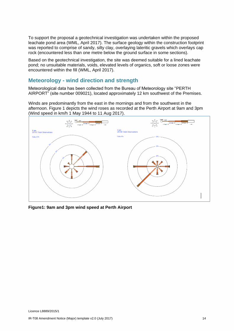
Meteorological data has been collected from the Bureau of Meteorology site “PERTH AIRPORT” (site number 009021), located approximately 12 km southwest of the Premises. Winds are predominantly from the east in the mornings and from the southwest in the afternoon. Figure 1 depicts the wind roses as recorded at the Perth Airport at 9am and 3pm (Wind speed in km/h 1 May 1944 to 11 Aug 2017).
Figure1: 9am and 3pm wind speed at Perth Airport

Licence L8889/2015/1 IR-T08 Amendment Notice (Major) template v2.0 (July 2017) 15
Risk assessment
Table 8 and 9 below describes the Risk Events associated with the proposal consistent with the Guidance Statement: Risk Assessments, for both the construction and operational phases. Both tables identify whether the emissions present a material risk to public health or the environment, requiring regulatory controls.
DWER has given consideration to the following aspects in its assessment:
siting of the proposed leachate ponds;
proposed emission controls during construction;
leachate pond design specifications, stability assessment and CQA procedures;
proposed operational controls and leachate management practices; and
proposed groundwater and surface water monitoring program.
Licence L8889/2015/1 IR-T08 Amendment Notice (Major) template v2.0 (July 2017) 16
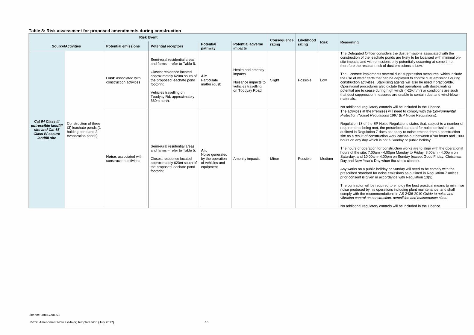
Table 8: Risk assessment for proposed amendments during construction
Risk Event Consequence rating
Likelihood rating
Risk Reasoning Source/Activities Potential emissions Potential receptors
Potential pathway
Potential adverse impacts
Cat 64 Class III putrescible landfill
site and Cat 65 Class IV secure
landfill site
Construction of three (3) leachate ponds (1 holding pond and 2 evaporation ponds)
Dust: associated with construction activities
Semi-rural residential areas and farms – refer to Table 5. Closest residence located approximately 620m south of the proposed leachate pond footprint. Vehicles travelling on Toodyay Rd; approximately 860m north.
Air: Particulate matter (dust)
Health and amenity impacts Nuisance impacts to vehicles travelling on Toodyay Road
Slight Possible Low
The Delegated Officer considers the dust emissions associated with the construction of the leachate ponds are likely to be localised with minimal on-site impacts and with emissions only potentially occurring at some time, therefore the resultant risk of dust emissions is Low. The Licensee implements several dust suppression measures, which include the use of water carts that can be deployed to control dust emissions during construction activities. Stabilising agents will also be used if practicable. Operational procedures also dictate that operations with dust-creating potential are to cease during high winds (>25km/hr) or conditions are such that dust suppression measures are unable to contain dust and wind-blown materials. No additional regulatory controls will be included in the Licence.
Noise: associated with construction activities
Semi-rural residential areas and farms – refer to Table 5. Closest residence located approximately 620m south of the proposed leachate pond footprint.
Air: Noise generated by the operation of vehicles and equipment
Amenity impacts Minor Possible Medium
The activities at the Premises will need to comply with the Environmental Protection (Noise) Regulations 1997 (EP Noise Regulations). Regulation 13 of the EP Noise Regulations states that, subject to a number of requirements being met, the prescribed standard for noise emissions as outlined in Regulation 7 does not apply to noise emitted from a construction site as a result of construction work carried-out between 0700 hours and 1900 hours on any day which is not a Sunday or public holiday. The hours of operation for construction works are to align with the operational hours of the site; 7.00am - 4.00pm Monday to Friday, 8.00am - 4.00pm on Saturday, and 10.00am- 4.00pm on Sunday (except Good Friday, Christmas Day and New Year’s Day when the site is closed). Any works on a public holiday or Sunday will need to be comply with the prescribed standard for noise emissions as outlined in Regulation 7 unless prior consent is given in accordance with Regulation 13(3). The contractor will be required to employ the best practical means to minimise noise produced by his operations including plant maintenance, and shall comply with the recommendations in AS 2436-2010 Guide to noise and vibration control on construction, demolition and maintenance sites. No additional regulatory controls will be included in the Licence.

Licence L8889/2015/1 IR-T08 Amendment Notice (Major) template v2.0 (July 2017) 17
Table 9: Risk assessment for proposed amendments during operation
Risk Event Consequence rating
Likelihood rating
Risk Reasoning Source/Activities Potential emissions Potential receptors
Potential pathway
Potential adverse impacts
Cat 64 Class III putrescible
landfill site and Cat 65 Class IV secure landfill
site
Operation of three (3) leachate ponds (1 holding pond and 2 evaporation ponds)
Odour: Storage of leachate
Semi-rural residential areas and farms – refer to Table 5. Closest residence located approximately 620m south of the proposed leachate pond footprint.
Air: Particulate matter (dust)
Health and amenity impacts
Minor Possible Medium
The Delegated Officer considers that leachate odour generated by the proposed leachate ponds will likely cause low-level on-site impacts and minimal off-site impacts, with emissions possibly occurring at some time. Therefore, the resultant risk of odour emissions is Medium. The distance and direction to the nearest house and the rural setting indicates a low-medium risk of potential impact from leachate storage. Prevailing winds (dominant wind characteristics) are from the east in the morning and then from the south-west in the afternoon. The closest residential receptor to the west of the site (in the direction of morning prevailing winds) is approximately 5km away. The closest residential receptor to the north-east of the site (in the direction of afternoon prevailing winds) is approximately 1km away. No additional regulatory controls will be included in the Licence.
Leachate: Leaks/discharges from conveyance infrastructure (piping failure)
Surface water – refer to Table 6.
Surface runoff
Eutrophication/ contamination of waterway which can disrupt ecosystem function
Slight Unlikely Low
Surface water: the Delegated Officer considers that leachate discharge from failure of conveyance infrastructure will likely cause minimal on-site impacts, with emissions unlikely to occur. Therefore, the resultant risk of leachate emissions impacting surface water from pond over-topping is Low. Groundwater: the Delegated Officer considers that leachate discharge from failure of conveyance infrastructure will likely cause low-level on-site impacts and minimal off-site impacts, with emissions unlikely to occur. Therefore, the resultant risk of leachate emissions impacting groundwater from pond over-topping is Medium. EMRC proposes to install a C220 Transfer Pump to transfer all the leachate from the decommissioned Class IV cell to the new leachate ponds. To convey leachate, PN 10/160mm pipe will be installed with joints electrofusion welded. Regulatory controls will be included in conditions of the Licence to ensure the conveyance infrastructure (pipe-work and pumps) is installed as per assessed design specifications.
Groundwater – refer to Table 7.
Seepage: Infiltration to ground
Contamination of waters or deterioration of local/ regional groundwater quality. Amenity and health impacts to users (potential potable, non-potable water uses).
Minor Unlikely Medium
Leachate: Leaks from liner failure
Groundwater – refer to Table 7.
Seepage: Infiltration to ground
Contamination of waters or deterioration of local/ regional groundwater quality. Amenity and health impacts to users (potential potable, non-potable water uses).
Major Unlikely Medium
The Delegated Officer considers the liner specifications of the leachate ponds will achieve a hydraulic conductivity of less than 1x10⁻⁹m/s or equivalent and is appropriate to prevent potential impacts arising from the storage of leachate. The proposed liner configuration consists of a 500mm thick Engineered Clay Attenuation Layer, overlain by a Geosynthetic Clay Liner (GCL), and then overlain by a 2mm High Density Polyethylene (HDPE) Double Textured Geomembrane (refer to ‘Pond design specifications’ section for further information). The Licensee also proposes to implement a series of quality assurance and quality control measures associated with general earthworks and liner installation. These measures are consistent with industry practice and standards. Regulatory controls will be included in conditions of the Licence to ensure construction of the leachate evaporation ponds adheres to the proposed lining specification and quality assurance and quality control (QA/QC) protocols. These measures will ensure that containment infrastructure will be constructed appropriately and thus mitigate against a contaminant pathway being present thus reducing the potential risk (level of impact). The QA/QC liner testing protocols are consistent with those stated in the Application and those outlined in the specifications published by the Geosynthetic Research Institute (GRI):
GRI-GCL3 - Standard Specification for “Test Methods, Required

Licence L8889/2015/1 IR-T08 Amendment Notice (Major) template v2.0 (July 2017) 18
Risk Event Consequence rating
Likelihood rating
Risk Reasoning Source/Activities Potential emissions Potential receptors
Potential pathway
Potential adverse impacts
Properties, and Testing Frequencies of Geosynthetic Clay Liners (GCLs)” (GRI, 2016); and
GRI - GM13 - Standard Specification for “Test Methods, Test Properties and Testing Frequency for High Density Polyethylene (HDPE) Smooth and Textured Geomembranes” (GRI, 2016)
The Delegated Officer notes that the Existing Licence does not currently include requirements to monitor surface water or groundwater. In accordance with MS requirements groundwater at the Premises is currently monitored on a quarterly basis and analysed for a range or inorganic and organic parameters. Information provided in a previous amendment application (refer to Amendment Notice 1 dated 6 September 2017) indicates that there are currently 47 bores that are monitored around the facility. EMRC reports these results annually in accordance with MS reporting requirements. A network of monitoring bores already exists in close proximity to the perimeter of the proposed leachate ponds (Attachment 1, Figure 3). This network consists of monitoring bores SP43S, FMB1 and FMB3 which are located cross to up-hydraulic gradient of the proposed leachate ponds and will provide background levels to monitor down-hydraulic gradient contaminant levels against. Monitoring bores SP4D, SP36D, SP37D, SP42D and SP46D are located down-hydraulic gradient from the proposed leachate ponds. The Delegated Officer considers the existing monitoring network is suitable to monitor changes in groundwater conditions and quality with regard to potential discharge of leachate constituents from the proposed leachate ponds. The proposed licence amendment does not propose to alter or duplicate requirements covered under these existing Ministerial Statements (see above).
Leachate: Overtopping of ponds
Surface water – refer to Table 6.
Surface runoff
Eutrophication/ contamination of waterway which can disrupt ecosystem function.
Slight Unlikely Low
Surface water: the Delegated Officer considers that over-topping of leachate ponds will likely cause minimal on-site impacts, with emissions unlikely to occur. Therefore, the resultant risk of leachate emissions impacting surface water from pond over-topping is Low. Groundwater: the Delegated Officer considers that over-topping of leachate ponds will likely cause low-level on-site impacts and minimal off-site impacts, with emissions unlikely to occur. Therefore, the resultant risk of leachate emissions impacting groundwater from pond over-topping is Medium. EMRC have advised that leachate levels in all ponds are monitored daily and a 500mm freeboard maintained at all times. Pumping infrastructure is in place to relocate leachate to other ponds should this be required to maintain the 500mm freeboard. EMRC have also proposed to construct diversion drains around the proposed leachate ponds which will capture stormwater run-off and divert to existing water collection ponds (refer to Attachment 1, Figure 2), thus removing potential run-off into the new ponds. All drains will be kept clear of any waste to ensure clear drainage and reduce the risk of contamination. The existing licence does not include conditions that require EMRC to maintain a freeboard equal to, or greater than, 500mm on leachate ponds, or a condition to maintain diversion drains around leachate ponds. Equivalent conditions are proposed to be included on the Licence as part of this Amendment Notice.
Groundwater – refer to Table 7.
Seepage: Infiltration to ground
Contamination of waters or deterioration of local/ regional groundwater quality. Amenity and health impacts to users (potential potable, non-potable water uses).
Minor Unlikely Medium

Licence L8889/2015/1 IR-T08 Amendment Notice (Major) template v2.0 (July 2017) 19
Decision
DWER has given regard to the outcome of the section 45c assessment as outlined in the ‘Legislative context – Part IV of the EP Act’ section to ensure that the decision and conditions for the proposed amended licence are not contrary to, or otherwise than in accordance with, an implementation agreement or decision of the Minister under Part IV of the EP Act.
Based on the Detailed Risk Assessment the Delegated Officer has determined to amend the Licence to authorise the construction and operation of three (3) leachate ponds (one holding pond and two evaporation ponds) within Lot 12.
The following amendments are proposed to the Existing Licence:
Authorisation to construct (3) leachate ponds (one holding pond and two evaporation ponds) and associated infrastructure as per the assessed design specifications (including CQA provisions).
Requirement to submit engineering certification from a suitably qualified professional confirming each item of infrastructure or component of infrastructure has been constructed with no material defects.
Operational controls to:
o maintain a freeboard equal to, or greater than, 500mm on leachate ponds; and
o maintain diversion drains around the leachate ponds.
Licensee’s comments
The Licensee was provided with the draft Amendment Notice on 31 May 2018. Comments received from the Licensee have been considered by the Delegated Officer as shown in Appendix 2.
Amendment
1. The Licence is amended by the insertion of the following definitions: ‘AS 1289.2.1.1’ means the Australian Standard AS 1289.1.1 Methods of testing soils for engineering purposes Soil moisture content tests – Determination of the moisture content of a soil – Oven drying method (standard method); ‘AS 1289 5.2.1’ means the ‘Australian Standard AS 1289 5.2.1 Methods of testing soils for engineering purposes - Soil compaction and density tests - Determination of the dry density/moisture content relation of a soil using modified compactive effort; ‘AS 3798- 2007’ Australian Standard AS 3798- 2007 Guidelines on earthworks for commercial and residential developments; ‘ASTM D792’ means the ASTM International Standard ASTM D792 Standard Test Methods for Density and Specific Gravity (relative Density) of Plastics by Displacement; ‘ASTM D1004’ means the ASTM International Standard ASTM D1004 Standard Test Method for Tear Resistance (Graves Tear) of Plastic Film and Sheeting; ‘ASTM D1505’ means the ASTM International Standard ASTM D1505 Standard Test Method for Density of Plastics by the Density-Gradient Technique;

Licence L8889/2015/1 IR-T08 Amendment Notice (Major) template v2.0 (July 2017) 20
‘ASTM D1603’ means the ASTM International Standard ASTM D1603 Standard Test Method for Carbon Black Content in Olefin Plastics; ‘ASTM D3895’ means the ASTM International Standard ASTM D3895 Standard Test Method for Oxidative-Induction Time of Polyolefins by Differential Scanning Calorimetry; ‘ASTM D4595’ means the ASTM International Standard ASTM D4595 Standard Test Method for Tensile Properties of Geotextiles by the Wide-Width Strip Method; ‘ASTM D4833’ means the ASTM International Standard ASTM D4833 Standard Test Method for Index Puncture Resistance of Geomembranes and Related Products; ‘ASTM D5199’ means the ASTM International Standard ASTM D5199 Standard Test Method for Measuring the Nominal Thickness of Geosynthetics; ‘ASTM D5397’ means the ASTM International Standard ASTM D5397 Standard Test Method for Evaluation of Stress Crack Resistance of Polyolefin Geomembranes Using Notched Constant Tensile Load Test; ‘ASTM D5641’ means the ASTM International Standard ASTM D5641 Standard Practice for Geomembrane Seam Evaluation by Vacuum Chamber; ‘ASTM D5721’ means the ASTM International Standard ASTM D5721 Standard Practice for Air-Oven Aging of Polyolefin Geomembranes; ‘ASTM D5820’ means the ASTM International Standard ASTM D5820 Standard Practice for Pressurized Air Channel Evaluation of Dual-Seamed Geomembranes; ‘ASTM D5885’ means the ASTM International Standard ASTM D5885 Standard Test Method for Oxidative Induction Time of Polyolefin Geosynthetics by High-Pressure Differential Scanning Calorimetry; ‘ASTM D5887’ means the ASTM International Standard ASTM D5887 Standard Test Method for Measurement of Index Flux Through Saturated Geosynthetic Clay Liner Specimens Using a Flexible Wall Permeameter; ‘ASTM D5890’ means the ASTM International Standard ASTM D5890 Standard Test Method for Swell Index of Clay Mineral Component of Geosynthetic Clay Liners; ‘ASTM D5993’ means the ASTM International Standard ASTM D5993 Standard Test Method for Measuring Mass Per Unit of Geosynthetic Clay Liners; ‘ASTM D6392’ means the ASTM International Standard ASTM D6392 Standard Method for Determining the Integrity of Nonreinforced Geomembrane Seams Produced Using thermos-Fusion Methods; ‘ASTM D6496’ means the ASTM International Standard ASTM D6496 Standard Test Method for Determining Average Bonding Peel Strength Between Top and Bottom Layers of Needle-Punched Geosynthetic Clay Liners; ‘ASTM D6693’ means the ASTM International Standard ASTM D6693 Standard Test Method for Determining Tensile Properties of Nonreinforced Polyethylene and Nonreinforced Flexible Polypropylene Geomembrane; ‘ASTM D6768’ means the ASTM International Standard ASTM D6768 Standard Test

Licence L8889/2015/1 IR-T08 Amendment Notice (Major) template v2.0 (July 2017) 21
Method for Tensile Strength of Geosynthetic Clay Liners;
2. The Licence is amended by the insertion of the following Conditions G10, G11, G12, G13, G14 and G15: LEACHATE POND CONSTRUCTION G10 The Licensee must install and undertake the Works for the infrastructure and
equipment: (a) specified in Column 1; (b) to the requirements specified in Column 2; and (c) at the location specified in Column 3
in Table A of Schedule 4 G11 The Licensee must not depart from the requirements specified in Column 2 of
Table A in Schedule 4 except: (a) where such departure does not increase risks to public health, public
amenity or the environment; and (b) all other Conditions in this Amendment Notice are still satisfied.
G12 Subject to Condition G11, within 30 days of the completion of the Works
specified in Column 1 of Table A in Schedule 4, the Licensee must provide to the CEO a report and engineering certification from a suitably qualified professional confirming each item of infrastructure or component of infrastructure specified in Column 1 of Table A in Schedule 4 has been constructed with no material defects and to the requirements specified in Column 2 of Table A in Schedule 4.
G13 Where a departure from the requirements specified in Column 2 of Table A in
Schedule 4 occurs and is of a type allowed by Condition G11, the Licensee must provide to the CEO a description of, and explanation for, the departure along with the certification required by Condition G12.
LEACHATE POND CONSTRUCTION QUALITY ASSURANCE G14 The Licensee must undertake quality assurance including visual inspection and
materials testing for the GCL and HDPE membrane specified in Condition G10 in accordance with Table B and Table C in Schedule 4.
G15 The report and engineering certification required by Condition G12 must be
accompanied by a Construction Quality Assurance (CQA) Validation Report that:
(a) is written and certified by the Geotechnical Inspection and Testing Authority that completed the construction quality assurance processes required by Table A, Table B and Table C in Schedule 4;
(b) certifies that the sub-grade and liner components are free of fault or defect, built to the design specification and fit for the intended purpose;
(c) assesses test results against minimum values in Table B and Table C in Schedule 4, including a summary of failures, corrective measures and retest results;
(d) demonstrates that a minimum separation distance of 5m between the lowest elevation of respective leachate ponds specified in Condition G10 and the highest recorded natural elevation of groundwater was achieved at the time of construction, as supported by on-site groundwater monitoring data;
(e) includes progress photos;

Licence L8889/2015/1 IR-T08 Amendment Notice (Major) template v2.0 (July 2017) 22
(f) includes copies of results of surveys and drawings of the final built leachate ponds and surface water diversion bunds,
(g) includes copies of results of surveys of inspections, monitoring and testing results for the sub-grade preparation and liner installation; and
(h) demonstrates compliance with Condition G10
3. The Licence is amended by the insertion of the following Schedule:
SCHEDULE 4
Table A – Infrastructure and Requirements
Column 1 Column 2 Column 3
Infrastructure/ Equipment
Requirements (design and construction) Site plan / drawing reference
Leachate ponds – General cconstruction quality assurance processes
The following works shall be subject to construction quality assurance processes in accordance with Level 1 of the Australian Standard AS 3798- 2007 Guidelines on earthworks for commercial and residential developments:
(a) the removal of unsuitable material, prior to the placement of compacted fill at the base and/or side slopes of the leachate ponds; and
(b) leachate pond construction, including liner placement, in accordance with the requirements specified in this Table.
N/A
Leachate ponds – dimensions and general arrangement
The leachate ponds are to be located in accordance with the Design Drawings in this Schedule.
Design Drawings in
in this Schedule
1) General Arrangement Plan
3) and 4) Pond Cross Sections
The leachate ponds shall be constructed to ensure that a minimum separation distance of 5m is achieved between the lowest elevation of respective leachate ponds and the highest natural elevation of groundwater recorded in surrounding monitoring bores.
Leachate ponds –configuration and liner permeability requirements
The liner configuration for each pond is to consist of the following:
(a) 500mm thick Engineered Clay Attenuation Layer using; overlain by a
(b) Geosynthetic Clay Liner (GCL) – hydraulic conductivity of ≤ 2.5 x 10⁻¹¹ m/s; overlain by a
(c) 2mm High Density Polyethylene (HDPE) Double Textured Geomembrane – hydraulic conductivity with a range from 1 x 10-14 to 1 x 10-15 m/s.
Design Drawings this Schedule
2) Typical Construction Sections and Details
Leachate ponds – Subgrade
The Licensee must design, excavate and construct the leachate ponds subgrade to achieve the following:
Design Drawings in
in this Schedule
1) General

Licence L8889/2015/1 IR-T08 Amendment Notice (Major) template v2.0 (July 2017) 23
Column 1 Column 2 Column 3
Infrastructure/ Equipment
Requirements (design and construction) Site plan / drawing reference
(a) formation surfaces shall be proof rolled with a 10 tonne dead-weight roller to prove the formations structural strength and capacity;
(b) unsuitable material shall be excavated and disposed of and filled with crushed rock material or similar;
(c) subgrade surface shall be constructed to the shape and levels as shown in the Design Drawings in this Schedule;
(d) during the whole of the compaction process the moisture content, at any point in the Lot, of the subgrade material shall be within ±2% of the optimum moisture content for that material;
(e) the completed subgrade layer shall be in a homogeneous uniformly bonded condition with no evidence of layering or disintegration;
(f) the completed subgrade surface shall be maintained in its conforming condition until construction commences and shall be watered as necessary to prevent shrinkage cracking, dusting or loosening of its surface;
(g) where material for a depth of 150mm below the subgrade surface contains more than 20% by mass of material retained on a 37.5mm sieve then that material shall be compacted as per provision (a) except that the vibratory pad-foot rolling shall be followed by no less than six (6) complete coverage by a fully ballasted 15 tonne rubber tyred roller; and
(h) the final surface shall be smooth and free from any sharp objects, stones, debris, water and desiccation cracks
Arrangement Plan
2) Typical Construction Sections and Details
3) and 4) Pond Cross Sections
Leachate ponds – 500mm thick Engineered Clay Attenuation Layer
The Licensee must design, excavate and construct a 500mm thick Engineered Clay Attenuation Layer to each leachate pond achieve the following:
(a) clay is to be moisture conditioned prior to placement as clay liner by thorough mixing and breaking down of clay clods, and where appropriate water addition, is required prior to placement and compaction;
(b) clay clods of greater than 300mm across shall not be placed prior to compaction;
(c) a vibratory sheepsfoot and/or padfoot roller or other suitable equivalent compaction plant shall be used for construction of the
Design Drawings in
in this Schedule
1) General Arrangement Plan
2) Typical Construction Sections and Details
3) and 4) Pond Cross Sections

Licence L8889/2015/1 IR-T08 Amendment Notice (Major) template v2.0 (July 2017) 24
Column 1 Column 2 Column 3
Infrastructure/ Equipment
Requirements (design and construction) Site plan / drawing reference
clay liner;
(d) the surface of compacted clay shall be sealed with a smooth roller after each lift. The smooth surface is then to be scarified and watered before the next lift of clay is placed;
(e) uncompacted lift thickness must not exceed 300mm;
(f) clay material shall have a moisture content, during and after compaction, within the range of optimum moisture content (OMC) -0% to +3% as determined by the methods of test within the Australian Standard AS 1289 5.2.1 Methods for testing of soils for engineering purposes, to >95% modified maximum dry density (MMDD);
(g) compacted clay liner shall and
(h) the final clay surface shall be protected from desiccation prior to geosynthetic placement. Surfaces containing desiccation cracks exceeding 12mm deep or exhibiting swelling, heaving or other similar conditions shall be replaced or reworked as per the above provisions.
Leachate ponds – Geosynthetic Clay Liner (GCL)
The Licensee must be design and construct a GCL to each leachate pond to achieve the following:
(a) GCL shall be a needle punched multi-layered system comprising two layers of geotextiles encapsulating a layer of dry bentonite;
(b) Overlying; and in contact with the Subgrade;
(c) Shall be securely anchored according to the specifications and dimensions as shown in the Design Drawings in Schedule 1;
(d) The seams shall have a minimum overlap of 300mm and shall be joined by the addition of bentonite powder, at a minimum of 0.3kg/m length of seam, unless the GCL has impregnated surfaces along sheet edges and is installed under the manufacturer’s guidelines; and
(e) Material properties meeting ‘minimum values’ as defined in Table B in this Schedule.
Design Drawings in
in this Schedule
1) General Arrangement Plan
2) Typical Construction Sections and Details
3) and 4) Pond Cross Sections

Licence L8889/2015/1 IR-T08 Amendment Notice (Major) template v2.0 (July 2017) 25
Column 1 Column 2 Column 3
Infrastructure/ Equipment
Requirements (design and construction) Site plan / drawing reference
Leachate ponds – High Density Polyethylene (HDPE) Double Textured Geomembrane
The Licensee must design and construct a HDPE Double Textured Geomembrane to each leachate pond to achieve the following:
(a) Manufactured specified thickness of 2mm;
(b) HDPE Membrane shall be uniform and free of pinholes, blisters, undispersed raw materials and contamination by foreign matter;
(c) Overlying; and in contact with the GCL;
(d) Shall be securely anchored according to the specifications and dimensions as shown in the Design Drawings in Schedule 1;
(e) There shall be no cross tie-in seams between batter and base panels within 2m of toe of batter;
(f) Material properties meeting ‘minimum values’ as defined in Table C in this Schedule.
Design Drawings in
in this Schedule
1) General Arrangement Plan
2) Typical Construction Sections and Details
3) and 4) Pond Cross Sections
Anchor trenches The Licensee must design and construct anchor trenches for the leachate ponds to meet the following:
(a) Anchor trenches for the geosynthetic liner components (GCL and HDPE) shall be constructed at the locations shown in the Design Drawings in this Schedule;
(b) The anchor trench shape and dimensions shall be as shown in the in the Design Drawings in this Schedule;
(c) Backfilled with material that was excavated from the anchor trench where the material is suitable otherwise it shall be replaced with clay material or other suitably equivalent material;
(d) Fill shall be placed and suitably compacted in horizontal layers not exceeding 150mm in thickness; and
(e) Marker posts must be installed once the backfilling has been completed to locate the centreline of the anchor trenches.
Design Drawings in
in this Schedule
1) General Arrangement Plan
3) and 4) Typical Construction Sections and Details
Leak detection survey
A leak detection survey must be undertaken following the installation of the HDPE geomembrane using either a water lance or arc testing method to detect any leaks/defects.
All anomalies shall be investigated and repaired where required.
N/A

Licence L8889/2015/1 IR-T08 Amendment Notice (Major) template v2.0 (July 2017) 26
Column 1 Column 2 Column 3
Infrastructure/ Equipment
Requirements (design and construction) Site plan / drawing reference
Following repairs, the area shall be locally resurveyed to ensure the defect was not masking further defects in the adjacent areas.
Stormwater diversion drains
Stormwater diversion drains must be installed around the perimeter of the proposed leachate ponds to prevent surface water run-off from entering the leachate ponds.
All drains are to be kept clear of any waste to ensure clear drainage and reduce the risk of contamination.
N/A
Leachate conveyance pipework
PN 10/160mm pipe must be installed with joints electrofusion welded.
N/A
Table B – Construction Quality Assurance Testing for GCL
Column 1 Column 2 Column 3 Column 4 Column 5
Item Property Standards/ Method
Frequency Minimum Value*
Conformance testing of GCL, following shipment to site
Mass per unit area of bentonite content
ASTM D5993 2,500m2 3,700g/m2
Montmorillonite content
X-ray diffraction method
10,000m2
70%
Mass of GCL ASTM D5993 4,000m2 4000g/m2
Moisture content (bentonite)
ASTM D5993
or
AS 1289.2.1.1
4,000m2 35% maximum (*no minimum)
Tensile strength ASTM D6768
or
ASTM D4595
10,000m2 4kN/m
Swell index
(free swell of clay/bentonite)
ASTM D5890 5,000m2 24 ml/2g
Peel strength ASTM D6496 4,000m2 360 N/m

Licence L8889/2015/1 IR-T08 Amendment Notice (Major) template v2.0 (July 2017) 27
Column 1 Column 2 Column 3 Column 4 Column 5
Item Property Standards/ Method
Frequency Minimum Value*
Permeability ASTM D5887 25,000m2
≤ 2.5 x 10⁻¹¹
m/s
Index flux ASTM D5887 25,000m2 1x10⁻⁸m3/s-m2
Visual inspection (on arrival and during placement)
Colour, thickness, needle punching, presence of needles or broken needles, and sewing density or other faults in the material
N/A Each roll Observed, validated and recorded by the consultant
Table C – Construction Quality Assurance Testing for HDPE Geomembrane
Column 1 Column 2 Column 3 Column 4 Column 5
Item Property Standards Frequency Minimum Value
Conformance following shipment to site
Thickness ASTM D5199
Each roll
2mm
Density ASTM D1505 or
ASTM D792
5,000m2, or every five rolls delivered to site, whichever is the greatest number
0.94g/cm3
Tensile properties:
Yield strength
Break strength
Yield elongation
Break elongation
ASTM D6693 Type IV
29kN/m
53kN/m
12%
700%
Puncture resistance
ASTM D4833 640N
Tear resistance ASTM D1004 249N
Carbon black content
ASTM D1603 2-3%
Stress crack resistance ASTM D5397 10,000m2, or
resin type or
300hr

Licence L8889/2015/1 IR-T08 Amendment Notice (Major) template v2.0 (July 2017) 28
Column 1 Column 2 Column 3 Column 4 Column 5
Item Property Standards Frequency Minimum Value
Oxidative induction time (OIT):
Standard OIT
or
High Pressure OIT
ASTM D3895
or
ASTM D5885
manufacturing run
100 min
400 min
Oven ageing and oxidative induction time at 85°C:
Standard OIT - % retained after 90 days
High Pressure OIT - % retained after 90 days
ASTM D5721
ASTM D3895
or
ASTM D5885
Per each formulation
55%
80%
Start-up test weld
Welding equipment N/A Start of works daily and whenever the welding equipment is shut-off for more than 1 hour. Also after significant changes in weather condition
N/A
Weld conditions N/A Test weld strips will be required whenever personnel or equipment are changed and/or wide temperature fluctuations are experienced. Minimum 1.5m continuous seam
N/A
Destructive weld testing
Onsite, hand tensiometer in peel and shear
ASTM D6392 Every weld
Observed, validated and recorded by the consultant
Non-destructive
Air pressure test ASTM D5820 All seams over full length
Observed, validated and recorded by

Licence L8889/2015/1 IR-T08 Amendment Notice (Major) template v2.0 (July 2017) 29
Column 1 Column 2 Column 3 Column 4 Column 5
Item Property Standards Frequency Minimum Value
weld testing the consultant
Vacuum box test ASTM D5641 Observed, validated and recorded by the consultant
Visual inspection
Tears, punctures, abrasions, cracks, indentation, thin spots, or other faults in the material
N/A Every roll
Observed, validated and recorded by the consultant

Licence L8889/2015/1 IR-T08 Amendment Notice (Major) template v2.0 (July 2017) 30
Design Drawing 1 – General Arrangement Plan for Leachate Ponds
Source: Drawing No C-010 from Letter Report: Design Principles of Evaporation Ponds at Red Hill Waste Management Facility (Talis, 22 December 2017)

Licence L8889/2015/1 IR-T08 Amendment Notice (Major) template v2.0 (July 2017) 31
Design Drawing 2 – Pond Construction Sections and Details
Source: Drawing No C-901 from Technical Specification Red Hill Waste Management Facility - Leachate Pond Construction (Talis, 31 October 2017)

Licence L8889/2015/1 IR-T08 Amendment Notice (Major) template v2.0 (July 2017) 32
Design Drawing 3 – Pond Cross Sections – Sheet 1
Source: Drawing No C-020 from Letter Report: Design Principles of Evaporation Ponds at Red Hill Waste Management Facility (Talis, 22 December 2017)

Licence L8889/2015/1 IR-T08 Amendment Notice (Major) template v2.0 (July 2017) 33
Design Drawing 4 – Pond Cross Sections – Sheet 2
Source: Drawing No C-020 from Letter Report: Design Principles of Evaporation Ponds at Red Hill Waste Management Facility (Talis, 22 December 2017)

Licence L8889/2015/1 IR-T08 Amendment Notice (Major) template v2.0 (July 2017) 34
4. Condition W2 of the Licence is amended by insertion of the red text shown in underline below: STORMWATER AND STORMWATER DRAINS W2(a) The licensee shall ensure stormwater is diverted from the active landfill cells,
leachate ponds and from previously filled areas of the site to dedicated stormwater drains.
W2(b) The licensee shall ensure stormwater drains are kept clear of any waste to
allow effective draining.
5. The Licence is amended by the insertion of Condition W5: LEACHATE PONDS W5 The Licensee shall manage all leachate ponds such that a freeboard equal to,
or greater than, 500mm is maintained.

Licence L8889/2015/1 IR-T08 Amendment Notice (Major) template v2.0 (July 2017) 35
Appendix 1: Key documents
Document title In text ref Availability
1 Licence L8889/2015/1 (Eastern
Metropolitan Regional Council, Red
Hill Waste Management Facility)
L8889/2015/1
accessed at www.dwer.wa.gov.au
5 DER Guidance Statement: Regulatory Principles (July 2015)
DER, 2015 accessed at www.dwer.wa.gov.au
6 DER Guidance Statement: Decision
Making (February 2017) DER, 2017
7 DER Guidance Statement: Risk
Assessments (February 2017) DER, 2017
8 DER Guidance Statement: Setting
Conditions (October 2015) DER, 2015
9 DER Guidance Statement:
Environmental Siting (November
2016)
DER, 2016

Licence L8889/2015/1 IR-T08 Amendment Notice (Major) template v2.0 (July 2017) 36
Appendix 2: Summary of Licensee comments
The Licence Holder was provided with the draft Amendment Notice on 31 May 2018 for review and comment. The Licence Holder responded on 19 June 2018. The following comments were received on the draft Amendment Notice.
Condition Summary of Licensee comment DWER response
N/A EMRC is still awaiting an outcome of the section 45C (Part IV – EP Act) assessment and understand that the amendment notice will be dependent upon and will need to reflect this outcome.
Noted. The section titled ‘Legislative context – Part IV of the EP Act’ has been updated to reflect the section 45c approval which was signed 26 June 2018.
N/A Assisted evaporation/ mechanical evaporator: in relation to the outstanding matters i.e. technical information relating to assisted evaporation, EMRC is in the process of preparing the information requested and will submit accordingly. In the interim, please do not include the assisted evaporation device in the current amendment package.
Assessment updated to reflect this request. The use of the assisted evaporation device has not been approved through this Amendment Notice. A separate licence amendment application should be submitted for assessment to facilitate its use.

Licence L8889/2015/1 IR-T08 Amendment Notice (Major) template v2.0 (July 2017) 37
Attachment 1:
Figure 1: Aerial map depicting the general area and boundaries of the proposed leachate ponds (Attachment 2 – EMRC, 14 November 2017)

Licence L8889/2015/1 IR-T08 Amendment Notice (Major) template v2.0 (July 2017) 38
Figure 2: Stormwater diversion drains – (Source: Drawing No C-050 from Technical Specification Red Hill Waste Management Facility - Leachate Pond Construction (Talis, 31 October 2017)

Licence L8889/2015/1 IR-T08 Amendment Notice (Major) template v2.0 (July 2017) 39
Figure 3: Map of the proposed groundwater monitoring points relating to the proposed leachate ponds - SP43S, FMB1 and FMB3 SP4D, SP36D, SP37D, SP42D and SP46D (Bores in blue circles)