Embed Size (px)
Citation preview
ANSIIBHMA A156.27-2011
Revision ofANSIIBHMA A156.27-2003
AMERICAN NATIONAL STANDARDFOR
POWER AND MANUAL OPERATED REVOLVING PEDESTRIAN DOORS
.. II...BHMAbuilders hardware manufact.urers
associ;.ition
SPONSOR
BUILDERS HARDWARE MANUFACTURERS ASSOCIATION, INC.
American Standards InstituteApproved June 20, 2011

AMERICAN NATIONAL STANDARD
An American National Standard implies a consensus ofthose substantially concerned with its scope and provisions.An American National Standard is intended as a guide to aid the manufacturer, the consumer and the general public.The existence ofan American National Standard does not in any respect preclude anyone, whether he has approvedthe standard or not, from manufacturing, marketing, purchasing, or using products, processes, or procedures notconforming to this standard. American National Standards are subject to periodic review and users are cautioned toobtain the latest editions.
CAUTION NOTICE: This American National Standard is permitted to be revised or withdrawn at any time. Theprocedures of the American National Standards Institute require that action be taken to reaffirm, revise, orwithdraw this standard no later than five years from the date of publication. Purchasers of American NationalStandards receive current information on all standards by calling or writing the American National StandardsInstitute.
Published byBUILDERS HARDWARE MANUFACTURERS ASSOCIATION, INC.
355 Lexington Avenue New York, New York 10017
Copyright © 2011 by theBuilders Hardware Manufacturers Association, Inc.
www.buildershardware.com
Not to be reproduced without specific authorization from BHMA
Printed in the USA
2
FOREWORD (This Foreword is not a part ofANSI/BHMA A156.27)
The general classification of builders hardware includes a wide variety of items which are divided intoseveral categories. To recognize this diversity, a sectional classification system has been established.Section P, Power Doors and Components is one such section and this Standard is a result of the collectiveefforts of members of the Builders Hardware Manufacturers Association, Inc. who manufacture thisproduct. The total Product Standards effort is, therefore, a collection of sections, each covering a specificcategory of items.
Performance tests and, where necessary, dimensional requirements have been established to ensure a degreeof safety. There are no restrictions on design except for those dimensional requirements imposed forreasons ofsafety.
This Standard is not intended to obstruct but rather to encourage the development of improved products,methods and materials. The BHMA recognizes that errors will be found, items will become obsolete, andnew products, methods and materials will be developed. With this in mind, the Association plans to update,correct and revise these Standards on a regular basis. It shall also be the responsibility of manufacturers torequest such appropriate revisions.
3
TABLE of CONTENTS
1. SCOPE 5
2. DEFINITIONS 5
3. GENERAL 7
4. MANUAL REVOLVING DOORS 8
5. AUTOMATIC REVOLVING DOORS WITH A CENTER SHAFT 8
6. AUTOMATIC REVOLVING DOORS WITH A CORE 10
7. AUTOMATIC TWO WING REVOLVING DOORS 11
8. ACCESS CONTROLLED REVOLVING DOORS 12
9. ACCESS CONTROLLED REVOLVING DOORS WITH ONE WAY FREE PASSAGE 12
10. REVOLVING DOOR EGRESS REQUiREMENTS 13
11. SIGNAGE 14
12. GLAZING 14
13. CLEARANCES ...................•.............................................................................................................................15
14. OBSTRUCTION FORCE 15
15. SLOW SPEED OPERATION AND ACTIVATION 15
16. WING SENSORS 15
17. END WALL AND BOTTOM RAIL GUARD SENSORS 16
18. KINETIC ENERGY REQUIREMENTS 16
19. DOOR OUT OF POSiTION 16
20. EMERGENCY STOP SWiTCH 16
21. ACTIVATING DEViCES 16
22 ENTRY POINTSENSOR 17
4
APPENDIX (NOT A PART OF A156.27) 18
1. SCOPE
1.1 Requirements in this standard apply to power operated revolving type doors which rotateautomatically when approached by pedestrians, some small vehicular use, and manual revolving typedoors for pedestrians. Included are provisions to reduce the chance of user injury and entrapment.Revolving doors for industrial or trained traffic are not covered in this Standard.
1.2 Where this standard contains specifications relating to maximum and minimum dimensions ofvarious components of revolving doors for pedestrian use and some small vehicular traffic, suchdimensions are included to provide user protection for what are in the industry, standard applicationconditions. This standard does not attempt to assess any factors that exist with respect to custominstallations.
1.3 Enclosure sizes shown in the charts shown are considered by the industry to be standard andpractical to meet the majority of the market needs and are shown as a guide and convenience to ownersand architects that are selecting a revolving door and as a convenience to installers and service personsadjusting the door and owners making periodic inspection. Deviation from enclosure sizes shown doesnot constitute non-compliance ifthe door complies with all requirements in the standard.
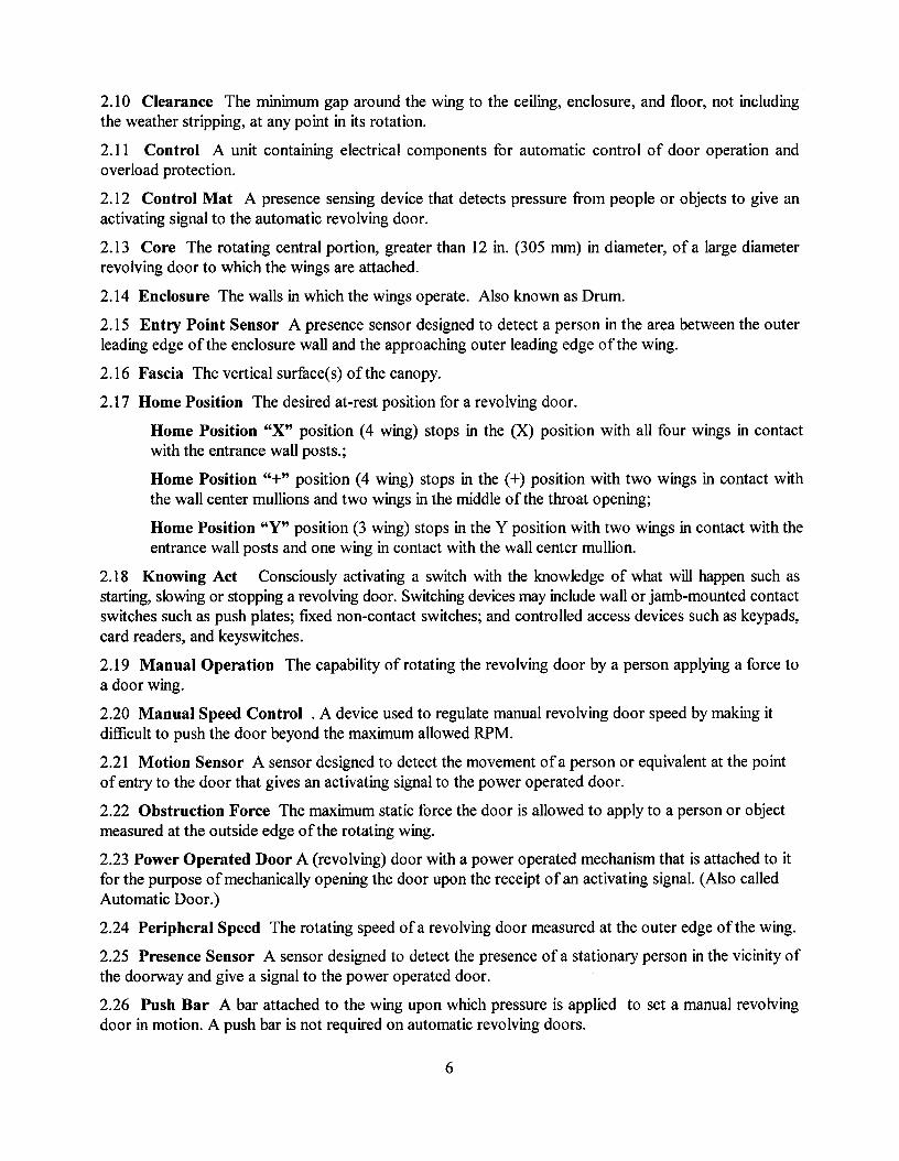
2. DEFINITIONS
2.1 Active Area An area where sensors detect presence or motion.
2.2 Automatic Door Operator A power operated mechanism that is attached to a revolving door forthe purpose of mechanically opening a door upon the receipt of an activating signal. (Also called apower door operator.)
2.3 Automatic Home Positioning Manual revolving doors with automatic home positioning are smalldiameter 3 or 4 wing revolving doors that utilize a Low Energy operator or mechanism to return thedoors to the Home position once a person exit the door and the door stops rotating.
2.4 Automatic Door Speed The rate at which an automatic revolving door rotates measured inrevolutions per minute (RPM). Three classifications are used:
Standard Speed The maximum allowable RPM for a revolving door.
Slow Speed One halfofstandard speed.
Low Energy Speed Door speed resulting in a maximum of2.5 lb£-ft. (3.4Nm) of kineticenergy.
2.5 Bookfold Position When each wing has been released from its fixed position permitting wings topivot in the direction ofegress.
2.6 Bottom Rail The lower horizontal member of the door wing.
2.7 Break Out A process whereby wings and/or door panels can be pushed open manually foremergency egress.
2.8 Canopy The area above the wings and enclosure comprised of a ceiling (soffit), fascia, and roof(optional).
2.9 Center Shaft The rotating center, 12 in. (305 mm) or less in diameter, of revolving doors to whichthe wings are attached.
5
2.10 Clearance The minimum gap around the wing to the ceiling, enclosure, and floor, not includingthe weather stripping, at any point in its rotation.
2.11 Control A unit containing electrical components for automatic control of door operation andoverload protection.
2.12 Control Mat A presence sensing device that detects pressure from people or objects to give anactivating signal to the automatic revolving door.
2.13 Core The rotating central portion, greater than 12 in. (305 mm) in diameter, of a large diameterrevolving door to which the wings are attached.
2.14 Enclosure The walls in which the wings operate. Also known as Drum.
2.15 Entry Point Sensor A presence sensor designed to detect a person in the area between the outerleading edge of the enclosure wall and the approaching outer leading edge of the wing.
2.16 Fascia The vertical surface(s) of the canopy.
2.17 Home Position The desired at-rest position for a revolving door.
Home Position "X" position (4 wing) stops in the (X) position with all four wings in contactwith the entrance wall posts.;
Home Position "+" position (4 wing) stops in the (+) position with two wings in contact withthe wall center mullions and two wings in the middle of the throat opening;
Home Position "Y" position (3 wing) stops in the Y position with two wings in contact with theentrance wall posts and one wing in contact with the wall center mullion.
2.18 Knowing Act Consciously activating a switch with the knowledge of what will happen such asstarting, slowing or stopping a revolving door. Switching devices may include wall or jamb-mounted contactswitches such as push plates; fixed non-contact switches; and controlled access devices such as keypads,card readers, and keyswitches.
2.19 Manual Operation The capability of rotating the revolving door by a person applying a force toa door wing.
2.20 Manual Speed Control. A device used to regulate manual revolving door speed by making itdifficult to push the door beyond the maximum allowed RPM.
2.21 Motion Sensor A sensor designed to detect the movement ofa person or equivalent at the pointofentry to the door that gives an activating signal to the power operated door.
2.22 Obstruction Force The maximum static force the door is allowed to apply to a person or objectmeasured at the outside edge of the rotating wing.
2.23 Power Operated Door A (revolving) door with a power operated mechanism that is attached to itfor the purpose ofmechanically opening the door upon the receipt ofan activating signal. (Also calledAutomatic Door.)
2.24 Peripheral Speed The rotating speed ofa revolving door measured at the outer edge of the wing.
2.25 Presence Sensor A sensor designed to detect the presence ofa stationary person in the vicinity ofthe doorway and give a signal to the power operated door.
2.26 Push Bar A bar attached to the wing upon which pressure is applied to set a manual revolvingdoor in motion. A push bar is not required on automatic revolving doors.
6
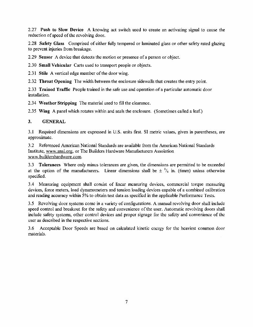
2.27 Push to Slow Device A knowing act switch used to create an activating signal to cause thereduction of speed of the revolving door.
2.28 Safety Glass Comprised of either fully tempered or laminated glass or other safety rated glazingto prevent injuries from breakage.
2.29 Sensor A device that detects the motion or presence ofa person or object.
2.30 Small Vehicular Carts used to transport people or objects.
2.31 Stile A vertical edge member of the door wing.
2.32 Throat Opening The width between the enclosure sidewalls that creates the entry point.
2.33 Trained Traffic People trained in the safe use and operation ofa particular automatic doorinstallation.
2.34 Weather Stripping The material used to fill the clearance.
2.35 Wing A panel which rotates within and seals the enclosure. (Sometimes called a leaf.)
3. GENERAL
3.1 Required dimensions are expressed in U.S. units first. SI metric values, given in parentheses, areapproximate.
3.2 Referenced American National Standards are available from the American National StandardsInstitute, www.ansi.org, or The Builders Hardware Manufacturers Assoiationwww.buildershardware.com.
3.3 Tolerances Where only minus tolerances are given, the dimensions are permitted to be exceededat the option of the manufacturers. Linear dimensions shall be ± 1/4 in. (6mm) unless otherwisespecified.
3.4 Measuring equipment shall consist of linear measuring devices, commercial torque measuringdevices, force meters, load dynamometers and tension loading devices capable of a combined calibrationand reading accuracy within 5% to obtain test data as specified in the applicable Performance Tests.
3.5 Revolving door systems come in a variety of configurations. A manual revolving door shall includespeed control and breakout for the safety and convenience of the user. Automatic revolving doors shallinclude safety systems, other control devices and proper signage for the safety and convenience of theuser as described in the respective sections.
3.6 Acceptable Door Speeds are based on calculated kinetic energy for the heaviest common doormaterials.
7
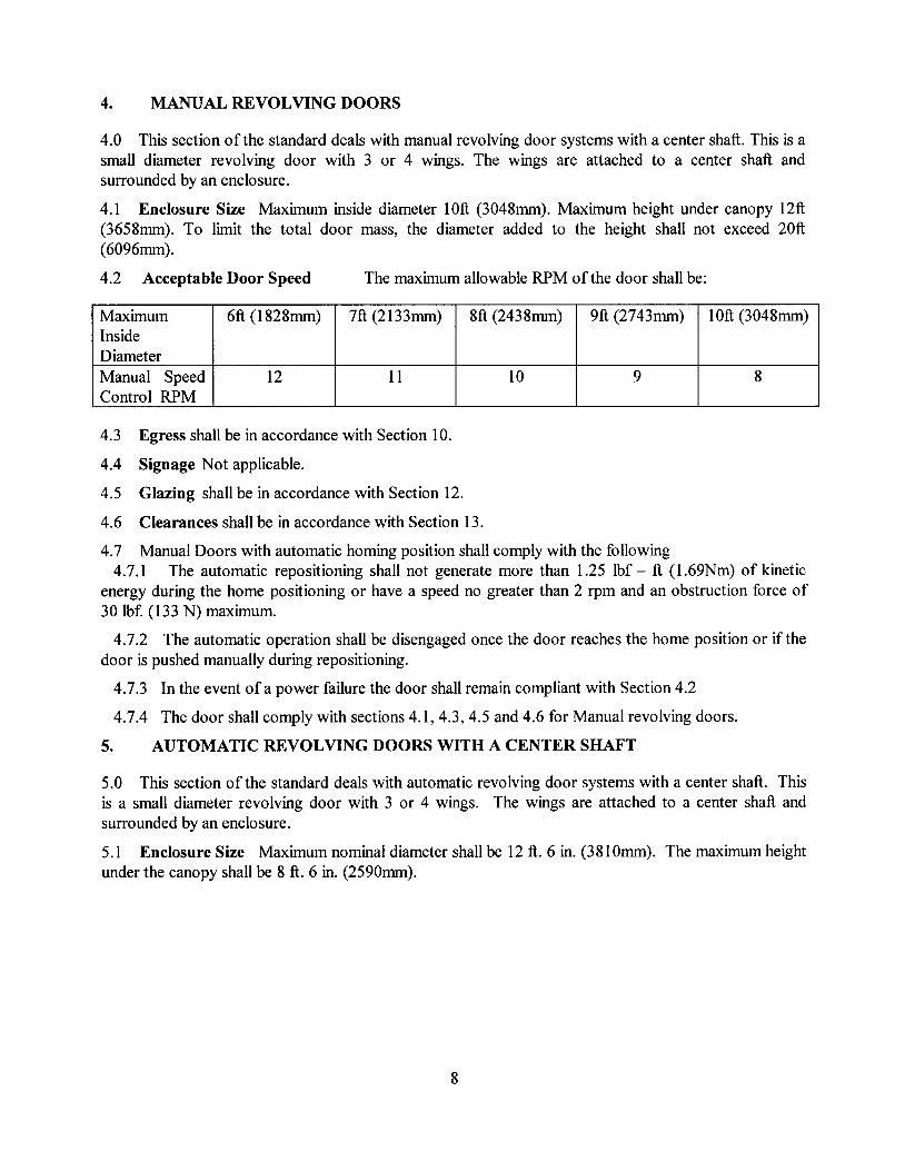
4. MANUAL REVOLVING DOORS
4.0 This section of the standard deals with manual revolving door systems with a center shaft. This is asmall diameter revolving door with 3 or 4 wings. The wings are attached to a center shaft andsurrounded by an enclosure.
4.1 Enclosure Size Maximum inside diameter 10ft (3048mm). Maximum height under canopy 12ft(3658mm). To limit the total door mass, the diameter added to the height shall not exceed 20ft(6096mm).
4.2 Acceptable Door Speed The maximum allowable RPM ofthe door shall be:
Maximum 6ft (l828mm) 7ft (2133mm) 8ft (2438mm) 9ft (2743mm) 10ft (3048mm)InsideDiameterManual Speed 12 11 10 9 8Control RPM
4.3 Egress shall be in accordance with Section 10.
4.4 Signage Not applicable.
4.5 Glazing shall be in accordance with Section 12.
4.6 Clearances shall be in accordance with Section 13.
4.7 Manual Doors with automatic homing position shall comply with the following4.7.1 The automatic repositioning shall not generate more than 1.25 lbf - ft (1.69Nm) of kinetic
energy during the home positioning or have a speed no greater than 2 rpm and an obstruction force of30 lbf. (133 N) maximum.
4.7.2 The automatic operation shall be disengaged once the door reaches the home position or if thedoor is pushed manually during repositioning.
4.7.3 In the event ofa power failure the door shall remain compliant with Section 4.2
4.7.4 The door shall comply with sections 4.1, 4.3, 4.5 and 4.6 for Manual revolving doors.
5. AUTOMATIC REVOLVING DOORS WITH A CENTER SHAFT
5.0 This section of the standard deals with automatic revolving door systems with a center shaft. Thisis a small diameter revolving door with 3 or 4 wings. The wings are attached to a center shaft andsurrounded by an enclosure.
5.1 Enclosure Size Maximum nominal diameter shall be 12 ft. 6 in. (381Omm). The maximum heightunder the canopy shall be 8 ft. 6 in. (2590mm).
8
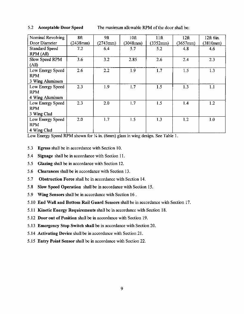
5.2 Acceptable Door Speed The maximum allowable RPM ofthe door shall be:
Nominal Revolving 8ft 9ft lOft 11 ft 12ft 12ft 6in.Door Diameter (2438mm) (2743mm) (3048mm) (3352mm) (3657mm) (3810mm)Standard Speed 7.2 6.4 5.7 5.2 4.8 4.6RPM (All)Slow Speed RPM 3.6 3.2 2.85 2.6 2.4 2.3(All)Low Energy Speed 2.6 2.2 1.9 1.7 1.5 1.3RPM3 Wing AluminumLow Energy Speed 2.3 1.9 1.7 1.5 1.3 1.1RPM4 Wing AluminumLow Energy Speed 2.3 2.0 1.7 1.5 1.4 1.2RPM3 Wing CladLow Energy Speed 2.0 1.7 1.5 1.3 1.2 1.0RPM4 Wing Clad
Low Energy Speed RPM shown for Y4 in. (6mm) glass in wing design. See Table 1.
5.3 Egress shall be in accordance with Section 10.
5.4 Signage shall be in accordance with Section 11.
5.5 Glazing shall be in accordance with Section 12.
5.6 Clearances shall be in accordance with Section 13.
5.7 Obstruction Force shall be in accordance with Section 14.
5.8 Slow Speed Operation shall be in accordance with Section 15.
5.9 Wing Sensors shall be in accordance with Section 16 .
5.10 End Wall and Bottom Rail Guard Sensors shall be in accordance with Section 17.
5.11 Kinetic Energy Requirements shall be in accordance with Section 18.
5.12 Door out of Position shall be in accordance with Section 19.
5.13 Emergency Stop Switch shall be in accordance with Section 20.
5.14 Activating Device shall be in accordance with Section 21.
5.15 Entry Point Sensor shall be in accordance with Section 22.
9
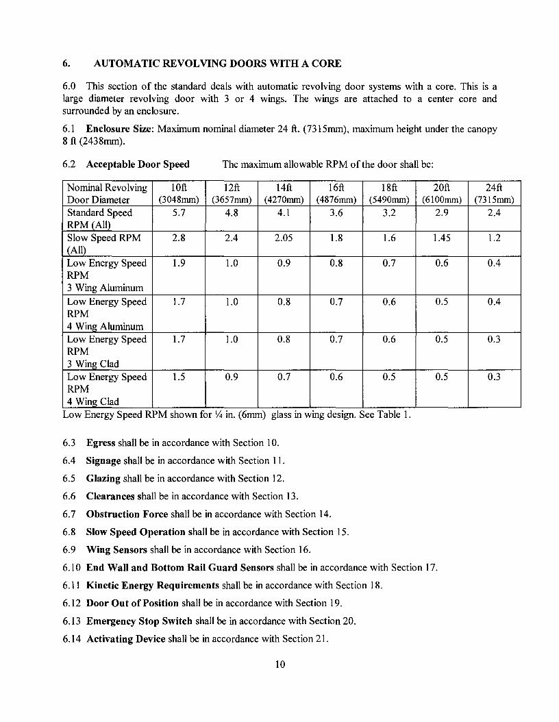
6. AUTOMATIC REVOLVING DOORS WITH A CORE
6.0 This section of the standard deals with automatic revolving door systems with a core. This is alarge diameter revolving door with 3 or 4 wings. The wings are attached to a center core andsurrounded by an enclosure.
6.1 Enclosure Size: Maximum nominal diameter 24 ft. (7315mm), maximum height under the canopy8 ft (2438mm).
6.2 Acceptable Door Speed The maximum allowable RPM of the door shall be:
Nominal Revolving 10ft 12ft 14ft 16ft 18ft 20ft 24ftDoor Diameter (3048mm) (3657mm) (4270mm) (4876mm) (5490mm) (6100mm) (7315mm)Standard Speed 5.7 4.8 4.1 3.6 3.2 2.9 2.4RPM (All)Slow Speed RPM 2.8 2.4 2.05 1.8 1.6 1.45 1.2(All)Low Energy Speed 1.9 1.0 0.9 0.8 0.7 0.6 0.4RPM3 Wing Aluminum
Low Energy Speed 1.7 1.0 0.8 0.7 0.6 0.5 0.4RPM4 Wing AluminumLow Energy Speed 1.7 1.0 0.8 0.7 0.6 0.5 0.3RPM3 Wing CladLow Energy Speed 1.5 0.9 0.7 0.6 0.5 0.5 0.3RPM4 Wing Clad
Low Energy Speed RPM shown for Y4 in. (6mm) glass in wing design. See Table 1.
6.3 Egress shall be in accordance with Section 10.
6.4 Signage shall be in accordance with Section 11.
6.5 Glazing shall be in accordance with Section 12.
6.6 Clearances shall be in accordance with Section 13.
6.7 Obstruction Force shall be in accordance with Section 14.
6.8 Slow Speed Operation shall be in accordance with Section 15.
6.9 Wing Sensors shall be in accordance with Section 16.
6.10 End Wall and Bottom Rail Guard Sensors shall be in accordance with Section 17.
6.11 Kinetic Energy Requirements shall be in accordance with Section 18.
6.12 Door Out of Position shall be in accordance with Section 19.
6.13 Emergency Stop Switch shall be in accordance with Section 20.
6.14 Activating Device shall be in accordance with Section 21.
10
6.15 Entry Point Sensor shall be in accordance with Section 22.
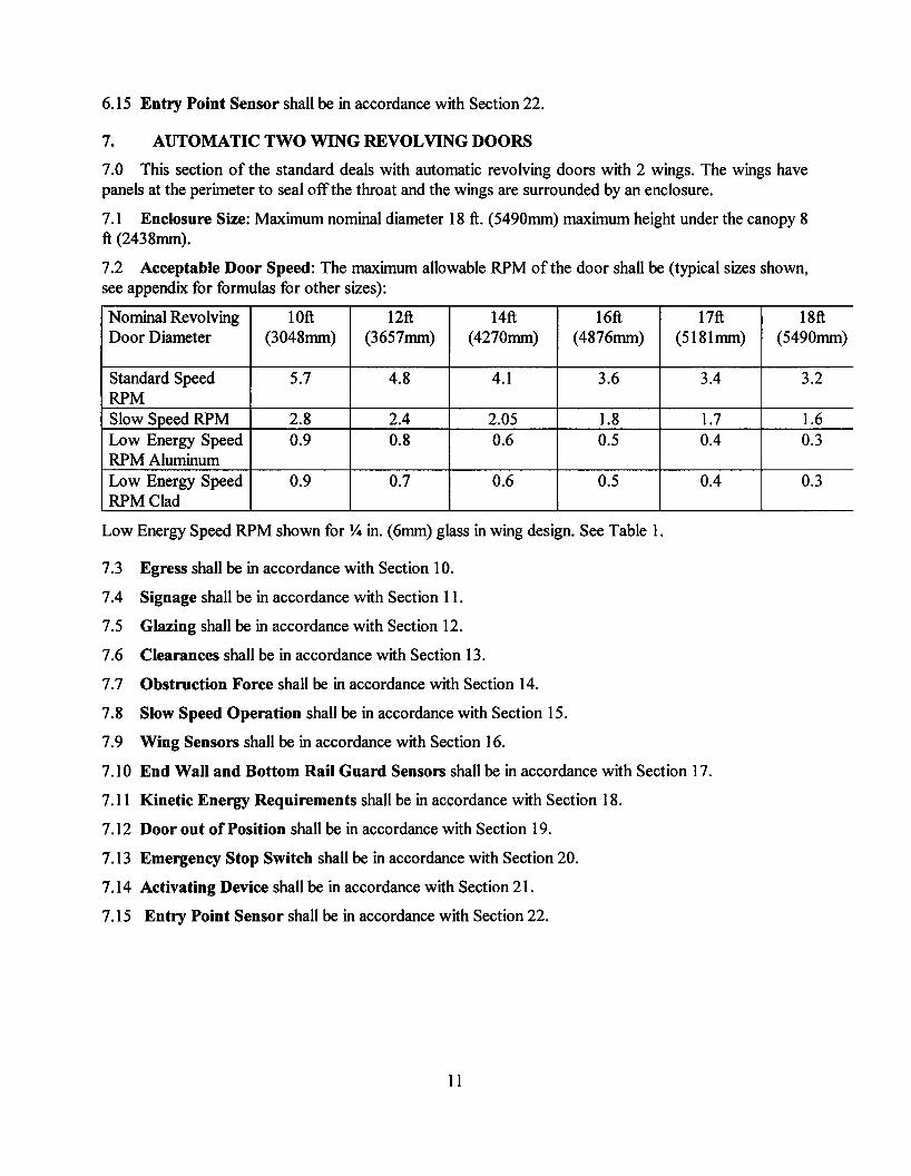
7. AUTOMATIC TWO WING REVOLVING DOORS
7.0 This section of the standard deals with automatic revolving doors with 2 wings. The wings havepanels at the perimeter to seal off the throat and the wings are surrounded by an enclosure.
7.1 Enclosure Size: Maximum nominal diameter 18 ft. (5490mm) maximum height under the canopy 8ft (2438mm).
7.2 Acceptable Door Speed: The maximum allowable RPM ofthe door shall be (typical sizes shown,see appendix for formulas for other sizes):
Nominal Revolving 10ft 12ft 14ft 16ft 17ft 18ftDoor Diameter (3048mm) (3657mm) (4270mm) (4876mm) (5181mm) (5490mm)
Standard Speed 5.7 4.8 4.1 3.6 3.4 3.2RPMSlow Speed RPM 2.8 2.4 2.05 1.8 1.7 1.6Low Energy Speed 0.9 0.8 0.6 0.5 0.4 0.3RPM AluminumLow Energy Speed 0.9 0.7 0.6 0.5 0.4 0.3RPM Clad
Low Energy Speed RPM shown for Y4 in. (6mm) glass in wing design. See Table 1.
7.3 Egress shall be in accordance with Section 10.
7.4 Signage shall be in accordance with Section 11.
7.5 Glazing shall be in accordance with Section 12.
7.6 Clearances shall be in accordance with Section 13.
7.7 Obstruction Force shall be in accordance with Section 14.
7.8 Slow Speed Operation shall be in accordance with Section 15.
7.9 Wing Sensors shall be in accordance with Section 16.
7.10 End Wall and Bottom Rail Guard Sensors shall be in accordance with Section 17.
7.11 Kinetic Energy Requirements shall be in accordance with Section 18.
7.12 Door out of Position shall be in accordance with Section 19.
7.13 Emergency Stop Switch shall be in accordance with Section 20.
7.14 Activating Device shall be in accordance with Section 21.
7.15 Entry Point Sensor shall be in accordance with Section 22.
11
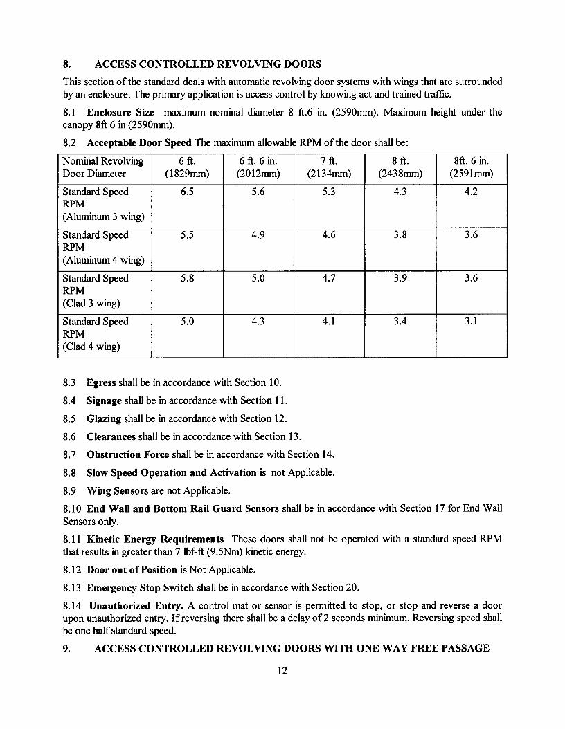
8. ACCESS CONTROLLED REVOLVING DOORS
This section of the standard deals with automatic revolving door systems with wings that are surroundedby an enclosure. The primary application is access control by knowing act and trained traffic.
8.1 Enclosure Size maximum nominal diameter 8 ft.6 in. (2590mm). Maximum height under thecanopy 8ft 6 in (2590mm).
8.2 Acceptable Door Speed The maximum allowable RPM ofthe door shall be:
Nominal Revolving 6 ft. 6 ft. 6 in. 7 ft. 8 ft. 8ft. 6 in.Door Diameter (l829mm) (2012mm) (2134mm) (2438mm) (2591mm)
Standard Speed 6.5 5.6 5.3 4.3 4.2RPM(Aluminum 3 wing)
Standard Speed 5.5 4.9 4.6 3.8 3.6RPM(Aluminum 4 wing)
Standard Speed 5.8 5.0 4.7 3.9 3.6RPM(Clad 3 wing)
Standard Speed 5.0 4.3 4.1 3.4 3.1RPM(Clad 4 wing)
8.3 Egress shall be in accordance with Section 10.
8.4 Signage shall be in accordance with Section 11.
8.5 Glazing shall be in accordance with Section 12.
8.6 Clearances shall be in accordance with Section 13.
8.7 Obstruction Force shall be in accordance with Section 14.
8.8 Slow Speed Operation and Activation is not Applicable.
8.9 Wing Sensors are not Applicable.
8.10 End Wall and Bottom Rail Guard Sensors shall be in accordance with Section 17 for End WallSensors only.
8.11 Kinetic Energy Requirements These doors shall not be operated with a standard speed RPMthat results in greater than 7 lbf-ft (9.5Nm) kinetic energy.
8.12 Door out of Position is Not Applicable.
8.13 Emergency Stop Switch shall be in accordance with Section 20.
8.14 Unauthorized Entry. A control mat or sensor is permitted to stop, or stop and reverse a doorupon unauthorized entry. If reversing there shall be a delay of2 seconds minimum. Reversing speed shallbe one half standard speed.
9. ACCESS CONTROLLED REVOLVING DOORS WITH ONE WAY FREE PASSAGE
12
9.0 This section of the standard deals with automatic revolving door systems with 2, 3 or 4 wings thatare surrounded by an enclosure. The primary application is one way free passage out of a controlled areaand to block access into the controlled area such as airport access. One Way Free Passage RevolvingDoors shall meet the requirements for the corresponding door type.
9.1 Enclosure Size Maximum nominal diameter shall be in accordance with the respective door typesspecified in Sections 5, 6, and 7.9.2 Acceptable Door Speed shall be in accordance with the respective door types specified inSections 5, 6, and 7.
9.3 Egress shall be in accordance with Section 10.
9.4 Signage shall be in accordance with Section 11.
9.5 Glazing shall be in accordance with Section 12.
9.6 Clearances shall be in accordance with Section 13.
9.7 Obstruction Force shall be in accordance with Section 14.
9.8 Slow Speed Operation shall be in accordance with Section 15 with the exception of only onedevice on the free passage side.
9.9 Wing Sensors shall be in accordance with Section 16.
9.10 End Wall and Bottom Rail Guard Sensors shall be in accordance with Section 17.
9.11 Kinetic Energy Requirements shall be in accordance with Section 18.
9.12 Door out of Position is not applicable.
9.13 Emergency Stop Switch shall be in accordance with Section 20.
9.14 Unauthorized Entry A control mat or sensor is permitted to stop, or stop and reverse a doorupon unauthorized entry. If reversing there shall be a delay of 2 seconds minimum. Reversingspeed shall be one half standard speed.
9.15 Activating Device Shall be in accordance with Section 21.
9.16 Entry Point Sensor shall be in accordance with Section 22.
10. REVOLVING DOOR EGRESS REQUIREMENTS
10.1 Egress Width Requirements When required under the applicable sections in this standard, arevolving door shall be capable of breakout with an egress path providing a 36in. (910mm) aggregateminimum width. Use of doors that do not breakout shall be approved by the authority havingjurisdiction.
10.1.1 Two wing doors with automatic center panels shall automatically open in the absence of linepower, activation of fife detection systems, or emergency stop functions. In the absence of line power orthe activation of the fife detection system, the door shall position for egress. The maximum force shallcomply with Section 14 Obstruction Force. (see figures 2 and 3).
10.2 Breakout Force Requirements
13
10.2.1 Egress Component Force Requirements Each revolving door wing shall be capable ofbreakout when a force 130 lb. (570 N) is applied at a point 3 in. (76 mm) from the outer edge of theouter wing stile and 40 in. (1020 mm) above the floor. Exception: Two wing doors with automaticcenter panels.
10.2.2 Other than Egress Component Force Requirements Each revolving door wing used otherthan as a component ofa means of egress shall be capable of breakout when a force of 180 lb. (790 N) isapplied at a point 3 in. (76 mm) from the outer edge of the outer wing stile and 40 in. (1020 mm) abovethe floor.
Exception A breakout force in excess of 180 lb. (801 N) is permitted if the breakout force isreduced to a maximum of 130 lb. (572 N) when at least one of the following conditions is satisfied.
1. When the power to the device holding the door wings in place is removed;
2. The revolving door is capable of receiving and responding to a signal that indicates theactuation of the automatic sprinkler system;
3. The revolving door is capable of receiving and responding to a signal that indicates theactuation ofa smoke detection system that is within 75 ft. (22,860 mm) of the revolving door;
4. A signal from a manual control reduces the holding force to a maximum 130 lb. (570 mm)force.
11. SIGNAGE
11.1 Consistent with section 2.2.1 of ANSI Z535.4, the "signage and warnings" guidelines of A156.27are recognized, industry-specific standards that predate the adoption of Z535.4 and are not replaced bythe standards set forth therein.
Automatic Door Sign Automatic revolving doors shall be marked with signage visible from both sidesofeach wing. The sign shall include the words "Automatic Door", minimum 1"(25mm) tall black lettersplaced at 50" +1- 12" (1270mm +1- 305mm) from the floor to the centerline of the sign. Additionalinformation may be included.
11.2 Slow Speed Activation Sign The sign shall read one of the following: "Activate to Slow", "Pushto Slow", or "Press to Slow". The letters shall be 5/s in. (16 mm) minimum tall and located within 12 in.(305 mm) of the device.
11.3 Emergency Stop Sign The sign shall read "Emergency Stop". The letters shall be 5/s in. minimum(16 mm) tall and located within 12 in. (305 mm) of the emergency stop switch.
12. GLAZING
12.1 When glazing is used in the wings and sidewalls it shall be 0.25 in. (6mm) minimum safety glass.All other glazing shall be 0.5 in. (13 mm) minimum safety glass.
14
13. CLEARANCES
13.1 Clearances The side clearance shall be a minimum of I Y2 in. (38mm) and a maximum of 3in.(76mm) between the rotating wing and the leading edge of the enclosure wall. The top clearance shall bea minimum of Y2 in. (12mm) except when the ceiling rotates with the wings. The bottom clearance shallbe a minimum of Y2 in. (l2mm) and a maximum of 2 in. (50mm). Exception: Access ControlledRevolving Doors are permitted to have tighter side clearances.
14. OBSTRUCTION FORCE
14.1 Obstruction Force The force required to prevent a stopped revolving door from rotating shall notexceed 50 Ibf(222 N) applied 1 in. (25 mm) from the outer edge of the outer wing stile.
15. SLOW SPEED OPERATION AND ACTIVATION
15.1 Slow Speed Operation Activation One device on the interior and one device on the exterior sidesof the door shall be placed within 48 in. (1220mm) of the right hand entry to the door. The device shallbe located between 24 to 48 in. (610 to 1220mm) from the floor. The activation area of the button shallbe a minimum of 1 in. (25 mm) diameter.
15.2 Slow Speed Operation Requirements Shall be a maximum of one half of the Standard Speedspecified by the applicable door type for a minimum ofone revolution.
16. WING SENSORS
16.1 Wing Sensor When wing sensors are required, they shall be effective to within lOin. (254mm)from the face of the wing. A wing sensor shall detect a 28 in. (710mm) minimum high person fully in therotation path of the wing sensor detection width, and shall cause the door to stop or slow to themaximum allowed kinetic energy speed. The effective wing sensor detection width shall be:
16.1.1 For Center Shaft Designs: within 2 in. (51mm) ofthe outer edge of the outer stile towithin 15 in. (380mm) from the axis.
16.1.2 For Core Designs: within 2 in. (51mm) of the outer edge of the outer stile to within 2 in.(51mm) of the core.
16.1.3 For Two Wing Designs: within 2 in. (51mm) from the leading edge of the outsiderotating enclosure to within 15 in. (380mm) min. from the axis except the portion of the rotating centerdoor panel or panels that move at a speed of 1.0 ft (305 mm) /sec. or less, do not require wing sensors,providing that the bottom rail sensor in that area complies with Section 17.2, and its activation causesthe door to stop within 2 in. (51mm) of travel measured from the point ofdetection. See Figures 4, 7and 8.
15
17. END WALL AND BOTTOM RAIL GUARD SENSORS
17.1 End Wall Leading Edge Sensor A sensing device shall detect an obstruction between therotating wings and the leading edge of the enclosure. It shall be active within 2 in. (51 mm) of the floorand shall be active for at least 60 in. (1520 mm) from the floor. Contact switches shall require no morethan 10 Ibf. (45N) pressure to activate. Upon receipt of a signal from the sensor, the door shall stoprotating. See Figure 11.
17.2 Bottom Rail Sensor A sensing device shall be active in the rotating path of the wing. It shall beactive within 2 in. (51 mm) from outer edge of the outer stile end and 6 in. (152 mm) from the center ofthe door and not higher than 4 in. (100 mm) from the fmished floor. Contact switches shall require nomore than 10 Ibf. (45N) pressure to activate. Upon receipt of a signal, the door shall stop rotating. Fortwo wing revolving doors see 16.1. Bottom rail sensors are not required on doors with an operatorsensing device or circuit, provided they provide equivalent performance. See Figure 4.
17.3 End Wall and Bottom Rail Sensor Sensitivity Test The circuit shall be activated when a solidtest fixture 3 in. by 3 in. (76mm x 76mm) is depressed with 10 Ibf (110 N) applied perpendicular to thesensor strip being tested. The sensor strip shall be tested in three locations 12 in. (305mm) apartcovering the active area. The test shall be conducted at 68 degrees ± 5 degrees F (20 degrees ± 2degrees C).
17.4 Cushioning Device The end wall and bottom rail shall be equipped with a cushioning device inlocation as described in 17.1 and 17.2. The sensor can be built into the cushioning devise or it can be aseparate item. Exception: two wing revolving doors with sliding panels.
18. KINETIC ENERGY REQUIREMENTS
18.1 Kinetic energy Doors which operate in the Standard Speed range and generate greater than 2.5 Ibf-ft(3.4 Nm) ofKE, shall be equipped with wing sensors that stop the door, or reduce the kinetic energy of thedoor to not more than 2.5 Ibf-ft (3.4 Nm) before contact.
19. DOOR OUT OF POSITION
19.1 Door out of position The door operator shall stop when a door wing is out of position amaximum of 15 degrees.
20. EMERGENCY STOP SWITCH
20.1 Emergency Stop Switch An emergency stop switch shall be provided that will stop the door'soperation. The door cannot resume rotation until the switch is manually reset. A minimum of oneemergency stop switch button shall be installed within 48 in. (l220mm) of the door and 24 in. (6IOmm)to 48 in. (1220 mm) above the floor. The activation area of the button shall be a minimum of 1 in. (25mm) diameter and shall be red.
21. ACTIVATING DEVICES
The activating device shall comply with either 21.1 or 21.2.
21.1 Motion sensors shall detect a 28 inch (71 Omm) minimum high person and moving at a rate of 6inches (150mm) per second minimum toward the center of the throat opening within the detection areas.Activating detection areas shall have a minimum width equal to the width of the throat opening. Theactivating detection area shall be effective to within 8 in. (203mm) of the arc of the rotating door, and
16
the length shall extend from the door 43 in. (1092mm) minimum from the arc of the wing. Refer toFigure 13.
21.2 Control mats shall conform to paragraph 7.6 Performance Requirements in ANSI/BHMAAI56.10-2005 Standard for Power Operated Doors. When used as an activating device for an automaticrevolving door, the detection area width shall be as wide as the throat opening less 5 inches (127mm)inactive area on each side, and have a length of 43 inches (1092mm) from the center of the throatopening. See Figure 11.
22 ENTRY POINT SENSOR
A presence sensing device shall be provided to detect a person entering a revolving door to prevententrapment between the wing and outer leading edge enclosure wall. Detection shall occur when the wing iswithin 20 in. (508mm) ofthe enclosure entry wall and cause the operator to stop or decelerate, with stoppageoccurring within lOin. (254mm) ofdetection or one second whichever occurs first. The sensor detection zoneshall be to the exterior of the entry point of the revolving door, and come to within 3 inches (7mm) of theouter edge of the rotating wing. The sensor shall detect a 28 in. (71Omm) minimum high person centered inthe area described for a minimum of 30 seconds. In the stop condition a person shall be capable of pushingthe door backwards to free themselves or others with a force not to exceed 40 lbf. (180N). See Figure 12.
Exception: Automatic doors with center shaft with a diameter up to 10ft. (3048mm) and operating at aStandard Speed lower than 7lbf-ft (9.5Nm) kinetic energy are not required to have an entry point sensor.
Automatic doors with a core with wings that will breakout (yield) with a force not to exceed 40 lbf. (180N)applied 3in. (75mm) at the outer edge ofthe outer wing stile and 28 in. (71Omm) from the floor.
Two wing automatic with a retracting leading edge that will retract or yield with a force not to exceed 40 lbs(180N) applied to the lead edge of the rotating enclosure 28 in. (710mm) from the floor with 6in. (152mm)max. ofretraction ofthe lead edge causing the door to stop.
17
APPENDIX (NOT A PART OF A156.27)
Information and drawings shown in the appendix are meant to clarify standard requirements, acquaintpersons with automatic revolving door terms. Revolving doors come in many configurations and types,and the omission of some does not mean they do not meet the standard provided they comply with therequirement in the standard.
Low Energy Speed Charts
These charts are shown as examples of the maximum RPM the door can operate under conditionsspecified in the standard. Maximum RPM varies depending on the weight of the door. The weight shownin these charts is typical aluminum and clad doors with Y4 in. (6mm) glass and 7ft. (2134mm) high doors.Weight will vary by manufacturer, type of glazing and type of metal construction of the door. Theindividual manufacturer's installation instructions and owner's manual should provide a chart for thedoor as it is installed so the installer will know how to adjust the door. Acceptable RPM is the maximumspeed the door can rotate. If the door exceeds the maximum RPM, it must be equipped with a wingsensor to stop or slow the door to the RPM shown under max. RPM at 2.5 lbf-ft (3.4Nm); exception isAccess Controlled Doors which are majority trained traffic users and in high security, and two wingdoors with center door panels as described in paragaph 16.1.
18
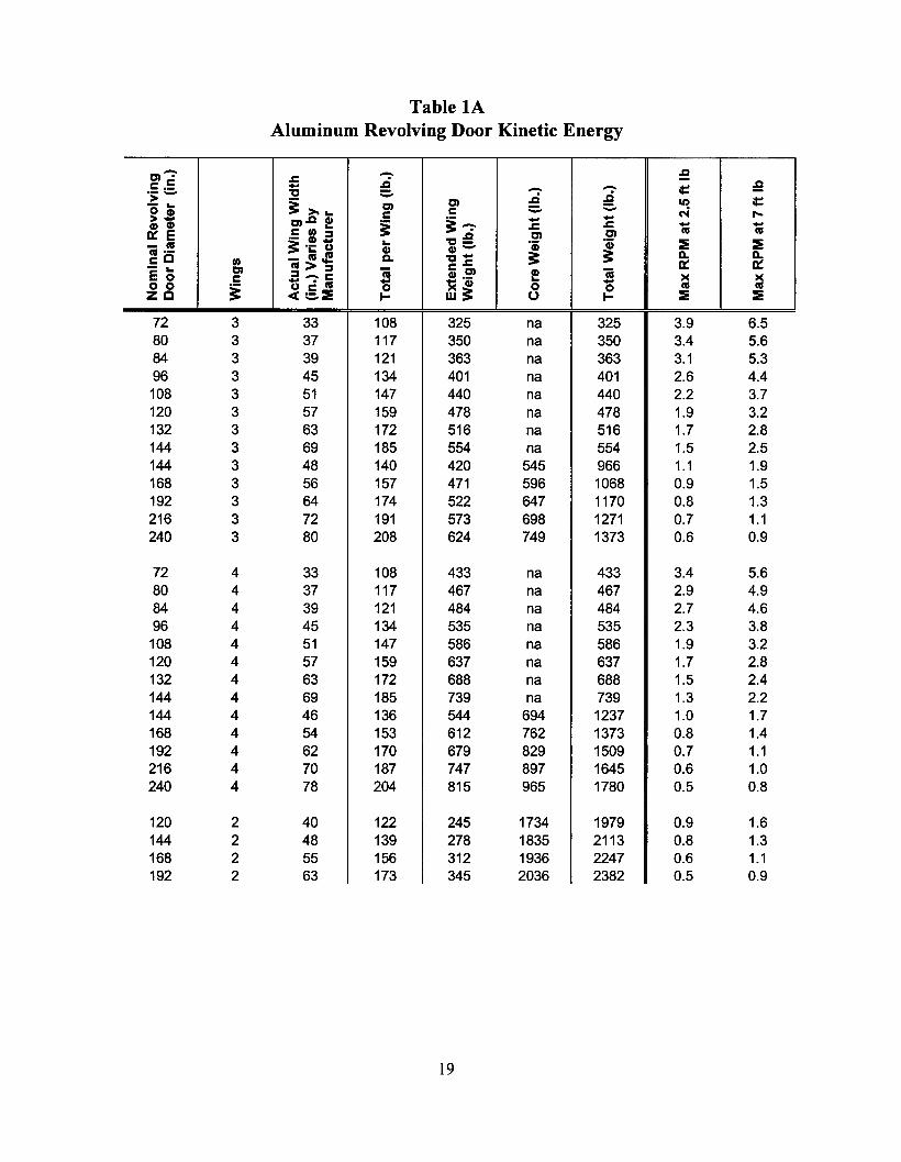
Table lAAluminum Revolving Door Kinetic Energy
- - J:lDI· .c~c.: - - - it:: :e':;- 't:l ::.
~ :9- .. 3: >- .. DI DI It) it::o (I) c c ::. - N ,...>- DI J:l (I) 3:--:- - -(I) (I) 3: .c .c - -n::E c I/) ..
DI DI as as,- (I) :::2 't:l:e-as ~'- 1) .. 'Qj
~:::!i :::!ias·- _:OJ! (I) (1)-
~ Q. Q.cO I/) Q. 't:l-as> :::2 c.c 0:: n::'E ~ DI :::2_c ii (I) ,!? ! ii )(c 1) .: as - ~~ - )(o 0 3: 0 0 0 as asZO <c :::.:::!i t- o t- :::!i :::!i
72 3 33 108 325 na 325 3.9 6.580 3 37 117 350 na 350 3.4 5.684 3 39 121 363 na 363 3.1 5.396 3 45 134 401 na 401 2.6 4.4108 3 51 147 440 na 440 2.2 3.7120 3 57 159 478 na 478 1.9 3.2132 3 63 172 516 na 516 1.7 2.8144 3 69 185 554 na 554 1.5 2.5144 3 48 140 420 545 966 1.1 1.9168 3 56 157 471 596 1068 0.9 1.5192 3 64 174 522 647 1170 0.8 1.3216 3 72 191 573 698 1271 0.7 1.1240 3 80 208 624 749 1373 0.6 0.9
72 4 33 108 433 na 433 3.4 5.680 4 37 117 467 na 467 2.9 4.984 4 39 121 484 na 484 2.7 4.696 4 45 134 535 na 535 2.3 3.8108 4 51 147 586 na 586 1.9 3.2120 4 57 159 637 na 637 1.7 2.8132 4 63 172 688 na 688 1.5 2.4144 4 69 185 739 na 739 1.3 2.2144 4 46 136 544 694 1237 1.0 1.7168 4 54 153 612 762 1373 0.8 1.4192 4 62 170 679 829 1509 0.7 1.1216 4 70 187 747 897 1645 0.6 1.0240 4 78 204 815 965 1780 0.5 0.8
120 2 40 122 245 1734 1979 0.9 1.6144 2 48 139 278 1835 2113 0.8 1.3168 2 55 156 312 1936 2247 0.6 1.1192 2 63 173 345 2036 2382 0.5 0.9
19
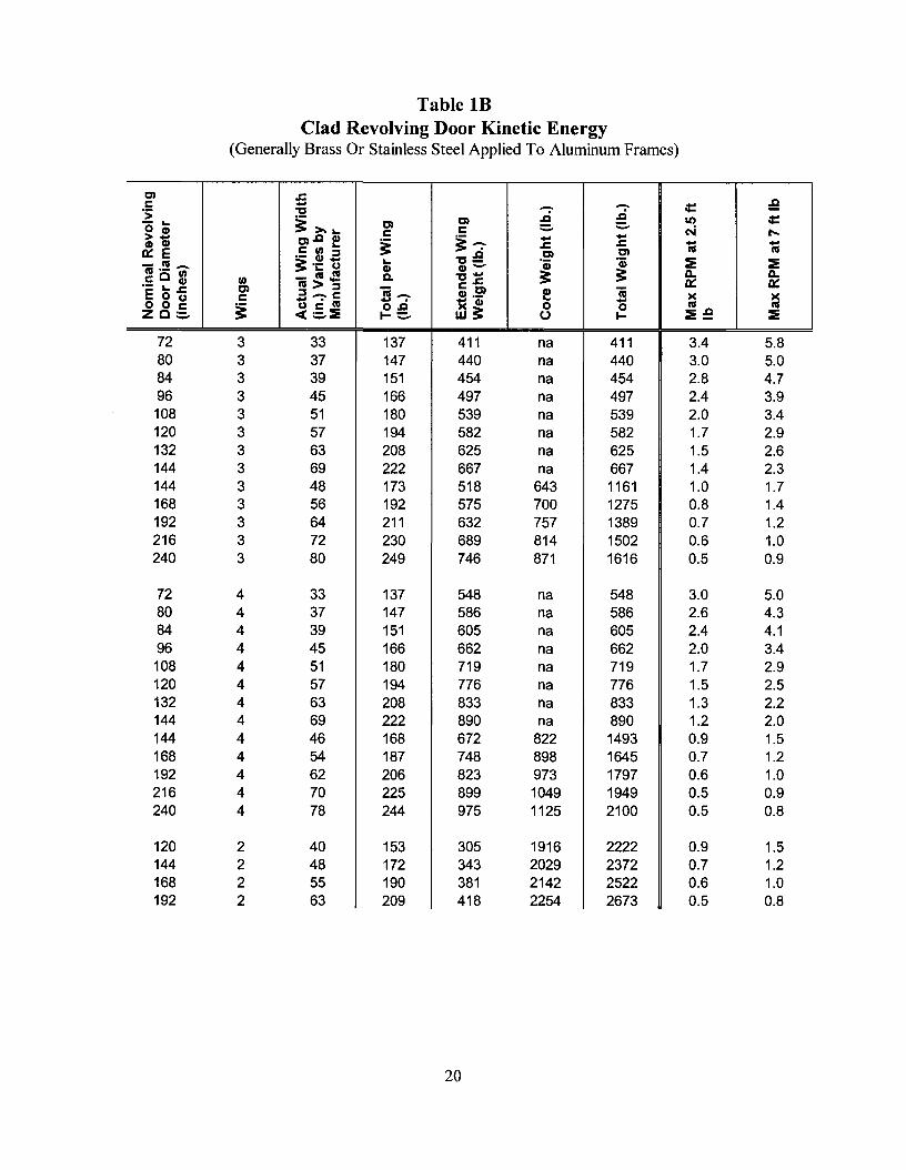
Table IBClad Revolving Door Kinetic Energy
(Generally Brass Or Stainless Steel Applied To Aluminum Frames)
C) .c .Qc - - - ot::'s; 't' .ci .ci- ... ~ >- ... C) C) &I) ot::o CD c - - N>- C).Q CD
C
~-:- - - .....CD CD ~ .c .c - -C III ... III III0:: E ,- CD ~ 't'~
C) C)
iU,!!! - 3: ,- 0 ... 'ii) 'ii) :E :ECD CD-c C :g -~J! c. 't'- 3: 3: 0.. 0..
III III > ~ c.c 0:: 0::,- ... .c C) iU_ CD.~ f iUE 0 (,) c ~-c >< ><Oc lll - . 1< CD -o 0 c~
O.Q 0 0 III IIIZC:.::.. <c :.::..::ll: 1-::- w3: u I- :E~ ::ll:
72 3 33 137 411 na 411 3.4 5.880 3 37 147 440 na 440 3.0 5.084 3 39 151 454 na 454 2.8 4.796 3 45 166 497 na 497 2.4 3.9108 3 51 180 539 na 539 2.0 3.4120 3 57 194 582 na 582 1.7 2.9132 3 63 208 625 na 625 1.5 2.6144 3 69 222 667 na 667 1.4 2.3144 3 48 173 518 643 1161 1.0 1.7168 3 56 192 575 700 1275 0.8 1.4192 3 64 211 632 757 1389 0.7 1.2216 3 72 230 689 814 1502 0.6 1.0240 3 80 249 746 871 1616 0.5 0.9
72 4 33 137 548 na 548 3.0 5.080 4 37 147 586 na 586 2.6 4.384 4 39 151 605 na 605 2.4 4.196 4 45 166 662 na 662 2.0 3.4108 4 51 180 719 na 719 1.7 2.9120 4 57 194 776 na 776 1.5 2.5132 4 63 208 833 na 833 1.3 2.2144 4 69 222 890 na 890 1.2 2.0144 4 46 168 672 822 1493 0.9 1.5168 4 54 187 748 898 1645 0.7 1.2192 4 62 206 823 973 1797 0.6 1.0216 4 70 225 899 1049 1949 0.5 0.9240 4 78 244 975 1125 2100 0.5 0.8
120 2 40 153 305 1916 2222 0.9 1.5144 2 48 172 343 2029 2372 0.7 1.2168 2 55 190 381 2142 2522 0.6 1.0192 2 63 209 418 2254 2673 0.5 0.8
20

Practical RPM Test Method
Divide the Maximum RPM into 60 seconds to get the Minimum Seconds per Revolution. Example: TheStandard speed maximum RPM for a 10 ft. (3048mm) shaft type revolving door is 5.7 revolutions per minuteas shown in the chart under 5.2 Acceptable Door Speed and the table shown in the Appendix. One revolutionat maximum speed is 60 seconds divided by 5.7 which equals 10.5 seconds minimum per revolution.
21
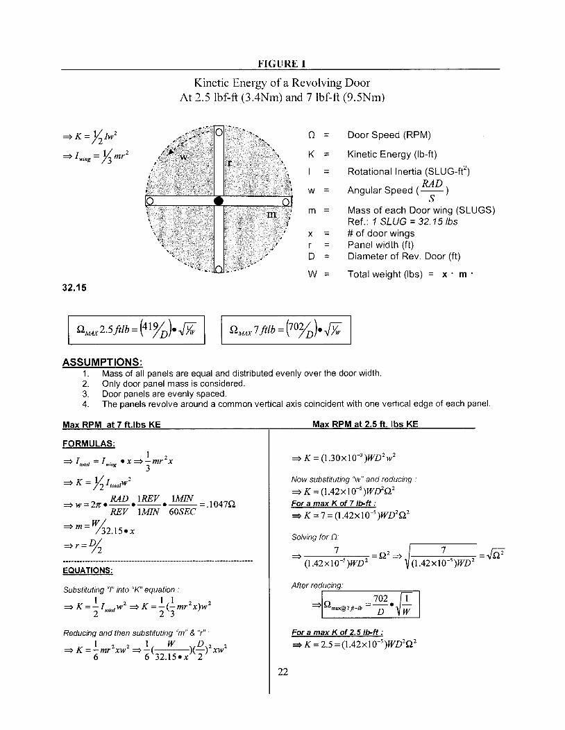
FIGURE 1
Kinetic Energy of a Revolving DoorAt 2.5 lbf·ft (3.4Nm) and 7 lbf-ft (9.5Nm)
~K= lilw2
~ I wing = Jj'mr2
(2 = Door Speed (RPM)
K = Kinetic Energy (Ib-ft)
I = Rotational Inertia (SLUG-fe)RAD
w = Angular Speed (--)S
m = Mass of each Door wing (SLUGS)Ref.: 1 SLUG = 32.15/bs
x = # of door wingsr = Panel width (ft)D = Diameter of Rev. Door (ft)
W = Total weight (Ibs) = x· m'32.15
QMAX 2.5ftlb =(41%).-&
ASSUMPTIONS:1. Mass of all panels are equal and distributed evenly over the door width.2. Only door panel mass is considered.3. Door panels are evenly spaced.4. The panels revolve around a common vertical axis coincident with one vertical edge of each panel.
Max RPM at 7 fUbs KE
FORMULAS:1 2
~ I to,al = I wing • X~ -mr x3
~ K = Ii ItotalW2
~ W = 27'. RAD .1REV • IMIN = .1047QREV IMIN 60SEC
~m-W/- /32.15.x
~r=%
EqUATIONS:
Substituting "/" into "K" equation.
1 2 1 1 2 2~K=-I'otaIW ~K=-(-mr x)w
2 2 3
Reducing and then sUbstituting "rn" & "r" •
1 2 2 1 W D 2 2~ K=-mr xw ~-( )(-) xw
6 6 32.15.x 2
22
Max RPM at 2.5 ft. Ibs KE
Now substituting "w" and reducing·
~ K = (1.42xlO-5 )WD2Q2For a max K of 7 Ib-ft :
~ K =7 =(1.42xIO-5 )WD2Q2
Solving for n.~ 7 =Q2 ~ 7 =N
(1.42xlO-5 )WD 2 (1.42xlO-5 )WD 2
After reducing:..--~------==-"'
~Q = 702. [Tmax@7ft-Ib D Vw
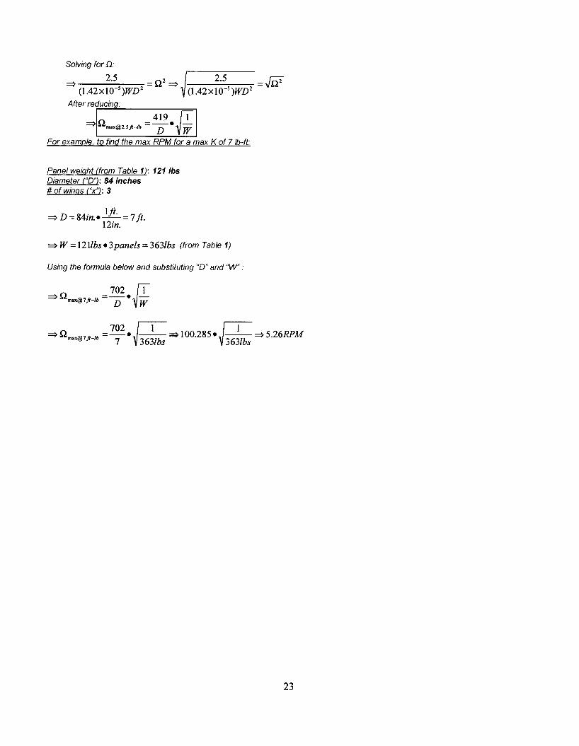
For a max K of 2.5 Ib-ft :
~ K =2.5 =(1.42xlO-5 )WD2Q2
Solving for D:
=> 2.5 = Q2 => 2.5 =.JQ2(l.42xl0-s)WD2 (l.42xl0-s)WD2
After red;::..:u:.;:c:;;.in:..:;zg,;..: -==''
=>Q =_41_9 e [[email protected] D Vw
For example, to find the max RPM for a max K of 7Ib-ft:
Panel weight (from Table 1): 1211bsDiameter ("0"): 84 inches# of wings C'x"): 3
=> D =84in. e 1ft· =7 ft.12in.
=>W=121lbs e 3panels=3631bs (from Table 1)
Using the formula below and substituting "0" and "W" :
=>Q = 702 e [Tmax@7jt-lh D Vw
702~ ~=>Qmax@7jtlh=-e ---=>100.285e ---=>5.26RPM- 7 3631bs 3631bs
23

FIGURE 2REVOLVING DOOR TYPES WITH TYPICAL BREAKOUT POSITIONS
If the fIxed portion of the wing is smaller than 12 in. (305mm) it is a shaft type. Ifthe fIxed portion is largerthan 12in. (305mm) it is a core design. Aggregate Parallel Egress = A'+ A2
Manual and Automatic Revolving Doors with a Center Shaft
Automatic Revolving Doors with a Core
Automatic 2-\Ving Revolving Doors
24
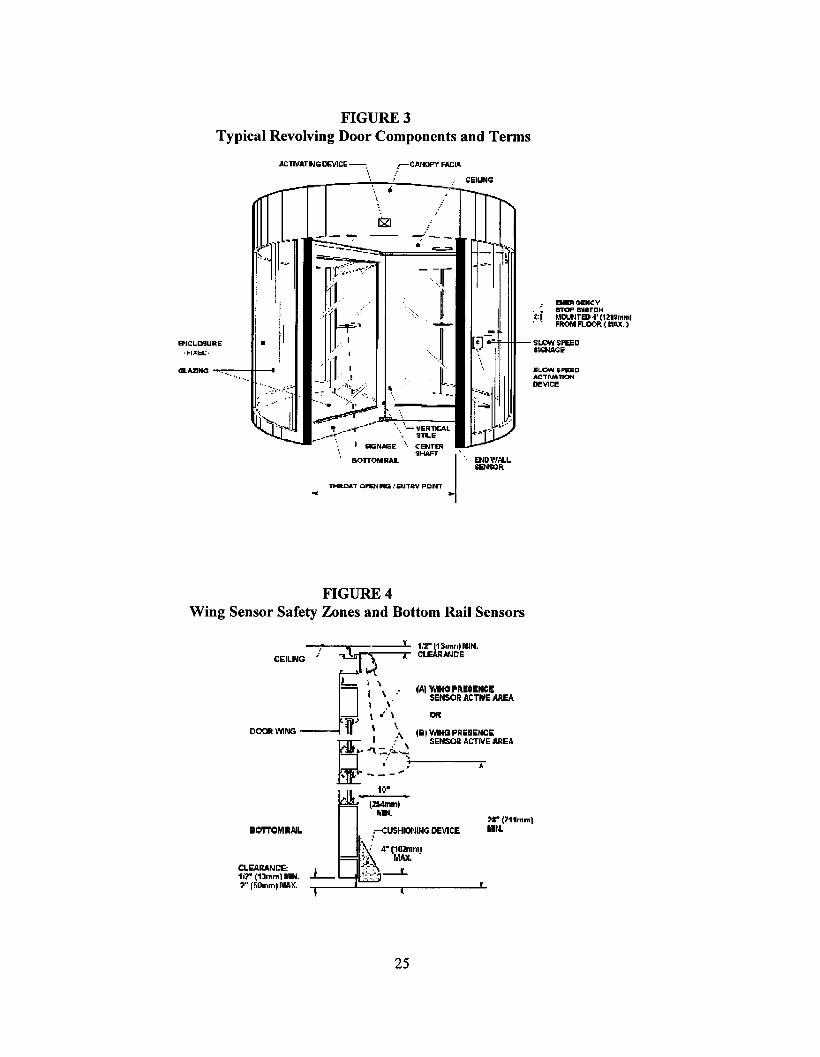
FIGURE 3Typical Revolving Door Components and Terms
AClIVArtlG CEVlCE-
..... CIiIUN<l
" .....
EIoBGENCYBTOP BVIITCH~'gl"tlr~ ". (121UmmlFROM FLOOR. ( r.lAlC. )
EtlllW....LSENSQR
=Cj-""""ff--ttt-- SI.QW$P&1l
'·~l ~~,
..
....~'-- -..
", "'-VERlTK;AL.... S1LE
I SO:;NAGE .... CENTER"HAFT
• IIOTTOM RAL
'I1«:DAT OPEJllr«l,'etnR... PDrn
-- -- ~
..
•El'JCLD!lURE
·t-I.xt:L:·
GLAZING ....,.,..• -".-••~H---O
FIGURE 4Wing Sensor Safety Zones and Bottom Rail Sensors
CEILNG~/~-----:;- ~3~~~~MIN.
J.I I \ (AI V~GPIl.E$ENeE
I \ SEN$CJR AtTflIE AREA, .'o)!.\. I'JR
DOOR \'fING W 'I \ lEU VdNG PR ESENCE
C!. SENSlCJIl AC'TIIIE AREA
=i~:!~~ ~~ 5"'0- ... _.- "'"
to·
BOTTOII1RAlL
CLEARANCE:1.7" (1~mml"'., .. f~Ommll\lA Jr.
,r(11tmmlMIl.
25
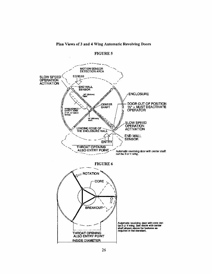
Plan Views of 3 and 4 Wing Automatic Revolving Doors
FIGURES
-_._-----""- ----- -"
./ / MOTION SENSOR -......... . DETECTION AREA .....
SLOW SPEED (EGRESS_------_ )OPERATION '\ I)··~--.... , ,.ACTIVATION .... /V -"- ~,
---END WAL.l.SENSOR
ij4 /ENCLOSURE( ~~ ~
~N ............ .+ DOOR OUT OF POSITION
'IIINGSENOOR / ~ 15" + MUST DEACTIVATESAFETY zot£ I ~ OPERATOR
III (T"I'P. AT EACH :-. I,ll\ ~ 'Nlmlj " " I ,'II.\. "-' II /1/W.~ '\.... IfI.~\~ ~ ".... ' 'II SLOW SPEED
"'" OPERATION, ~D~~gL~~~~~Ail--- . ACTIVATION... '-.. ff/r
)f -,.. ~~. __ ~ I" END WALL
( .~--. -. - --"ENTRyi ) SENSOR
" THRQATOPENfNG ~/'
",-~~SOENTRY POI~ ,-' Automatic rlM1lving door with oenter shaft--. - _._ ~ --- _.- can be 3 or 4 wing.
FIGURE 6
THROAT OPENINGAlSO ENTRY POINTINSIDE DIAMETER
26
AutomatiC revolving dOOr Vtllh core canbe 3 or 4 wing. see 000111 with centershaft shown above for JeatLnS allrequired In the standard.
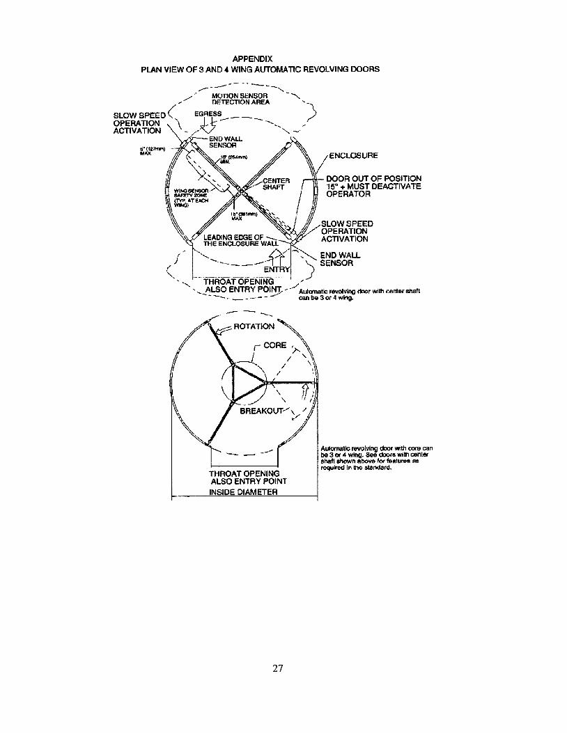
APPENDIXPLAN VIEW OF 3 AND" WING AUTOMATIC REVOlVING DOORS
/ENCLOSURE
DOOR OUT OF POSITION15" + MUST DEACTIVATEOPERATOR
" I"\~JV~~~}'{A~~D
LEADING EDGE OF--. ACTIVATIONTI-lE ENCLOSURE WALL
/~ --'''-",. i-:X-' ~ END WALLI' '--~_-,"'f I ) SENSOR
ENTRY\,.,
"", ., "'THROAT'OPENING' ./'-',- ALSO ENTRY POINT- - . Aulanatic reYlliving d:lor witl1 center sIlaft
- '-. __ ~_.....-- canbe3or4 Whg.
r"'"'-"""""---- - .....~ .... --,...
I\,tQll0N SENSOR - .........DETECTION AREA 1
SLOW SPEED ( EGRESS..- _ _ __ )OPERATION \ ~~-l; --,,-ACTIVATION - / v " -'
END WALLSENSOR
--- ---""
THROAT OPENINGALSO ENTRY POINTINSIDE DIAMETER
AutQmiltIc revolving door wrth torl/ (:<Inbe 3 Of 4 wing. See OXJl'$ Wi1h C«Ilershaftshiown aboVe lOt' 19atuM!lI 8Srcql.P'cd In no Gtllndord.
27
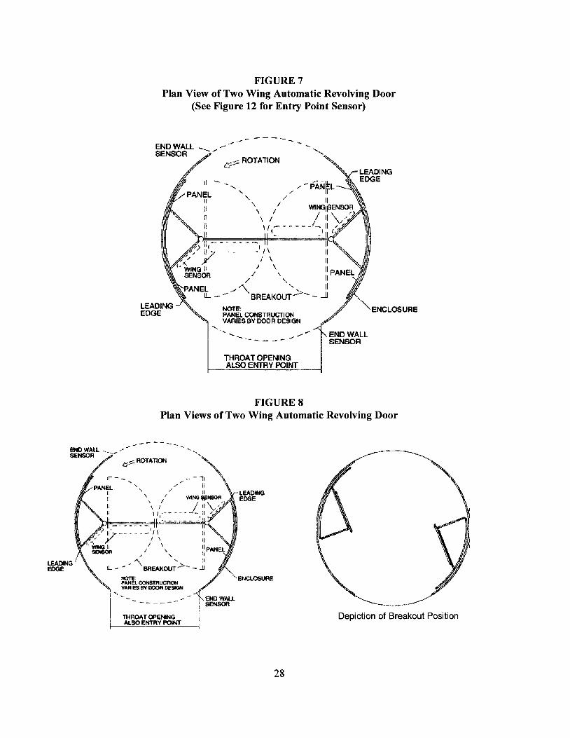
FIGURE 7Plan View of Two Wing Automatic Revolving Door
(See Figure 12 for Entry Point Sensor)
.-- --- - "-
NOTE:PANEL CONSTFlUCTIONVARIES av DOOR DESIGN
" ENCLOSURE
-" .,.. END WALLSENSOR
In/ \
I \
/ "
"- --- - ---
END WALL _ -" .- ~.
SENSOR --/t::-:;:::::" ROTATION
THROAT OPENINGALSO ENTRY POINT
FIGURESPlan Views of Two Wing Automatic Revolving Door
Depiction of Breakout Position
LEADlHGEDGE
") 1,'-
\ I" ,/
II_I J \ it
1 " II
/ \.. lipAN/ " 'I
"" :IIL - -~. "BREAJ(Ol/T-'>- - Jl
~LCON$Ti'lUCl'lOtl ", ENCLOSURE
"'l '. VIofl.IES1lY~ DESIGN '•.•.... - - - '}.. Ef,IO WAU--------- :SENSOR
ITHf'lOAT OPENING I
. ALSO ENTRY POINT i
--_ ..... '''------END WAll. ~_ .,..-seNSOR -
1:;:::::- ROTATION
28
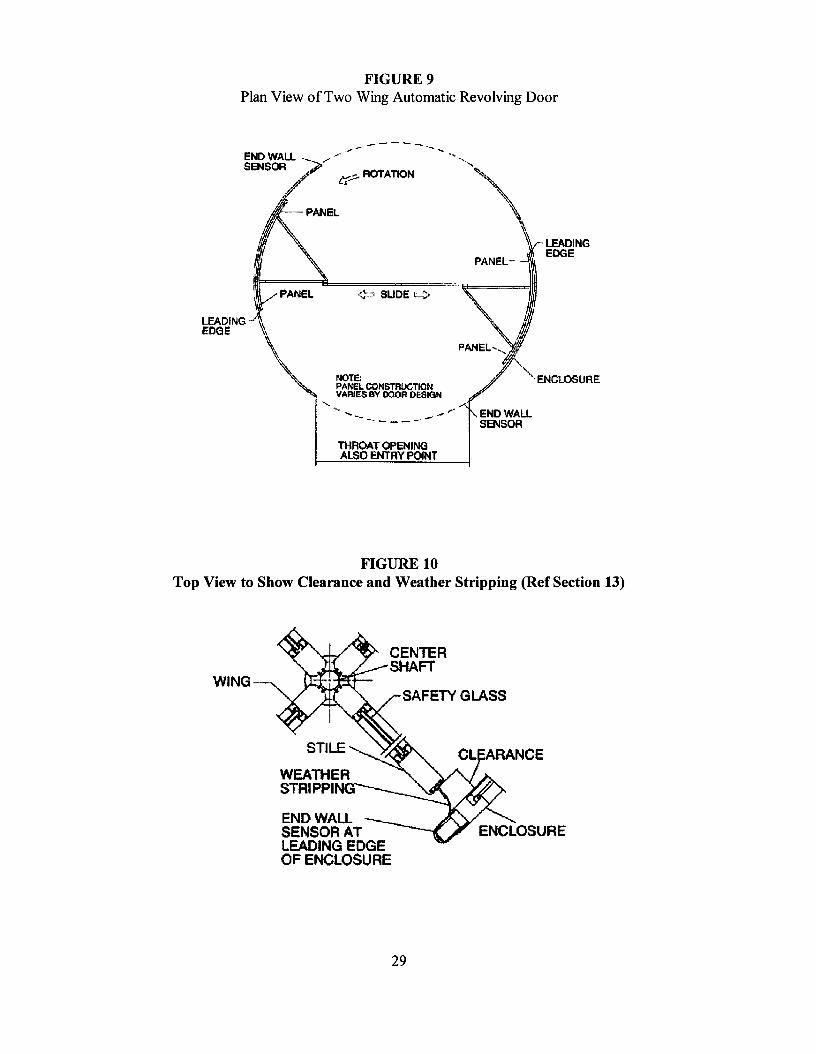
FIGURE 9Plan View ofTwo Wing Automatic Revolving Door
LEADINGEDGE
"'-·ENCLOSURE
,.
'¢:::1 SLIDE ¢
,~-
-~ - - --
"",-::;.;ROTATIONL,J:-
'IOTE:PANEL CON5TRUCTIO~VARIES BY OOOR DESIGN
ENDWALL -_SENSOR
LEADING- ~EDGE Ii,
\..~
THROAT OPENINGALSO ENTRY P04NT
FIGURE 10Top View to Show Clearance and Weather Stripping (Ref Section 13)
SAFETY GLASS
STILE
WEATHERSTRIPPING
END WALLSENSOR ATLEADING EDGEOF ENClOSURE
WING
29
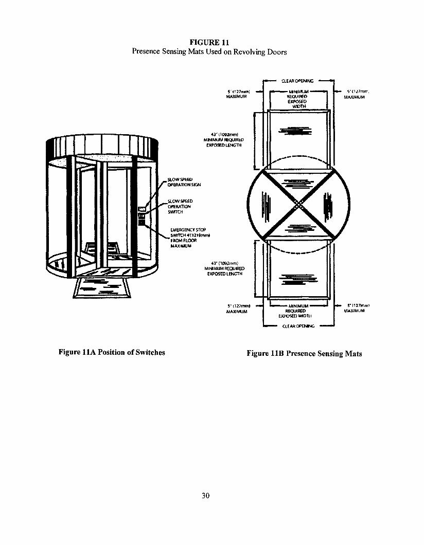
FIGURE 11Presence Sensing Mats Used on Revolving Doors
S" C117mm)MAXIMUM """'MUMREOUI!1l?O
ElCfOSEOWIDTH
5"0l1mm;MAXIMUM
ClEAR OP£NING
S·"27mmlMAXIMUM
43" (1092mrnjMINIMUM REQUIRED
EXPOSED LENGTH
5"1127mmlMAXIMUM
43" (1092mm)MI"'MUM Rt:OtJIIlEO
EXPOSro LENGTH
EMERGENCY SToPSWlTC~4'112'~rnm~
FltOMFlOORMAXIMUM
Figure 11A Position of Switches Figure 11B Presence Sensing Mats
30
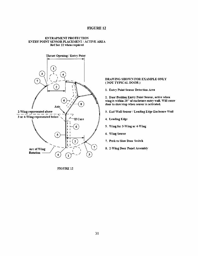
FIGURE 12
E:NTRAPMENT PROTECTIONENTRY POINT SENSOR PLO\CEMENT i ACTIVE AREA.
Rt'f St'c 22 wht'n rt'quired
Thl'oat Opening / Entry Point
"-
Arc of Wing )' --Rotation~
4
5. Wing for 3-Wing or 4-Wing
7. Push to Slow Door Switch
4. Leading Edge
6. 'Viug St'nsor
S. 2-Wing Door Panel Ac;st'mbly
3. End Wall St'llsor I Lt'ading Edgt' Enclosure WaU
DRAWING SHOWN FOR EXA1\IPLE ONLY( NOT TYPICAL DOOR)
1. Entry Point St'nsor Dt'tection Area
2. Door Position Entl"y Point St'nsor, active when"ing is 'nithin 20" of enclosure entry wall. Will causedoor to slow/stop when sensor is acti\'att'd.
cp/ "\ , /-.--
1.~0 II\ \\ \
I I --=(;\_ I~I/
I II .,._.f8\A.us '....~J
2-'Ving represented abovt' '"----------"'""-3 or 4-'Ving reprt'sentt'd below "
FIGURE 12
31
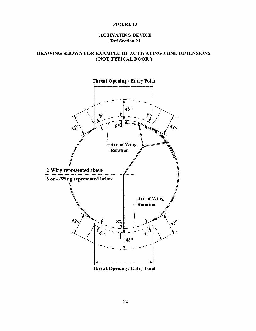
FIGURE 13
ACTIVATING DEVICERef Sl"ction 21
DRA\~VING SHO\VNFOR EXA.l\'IPLE OF ACTIVATING ZONE DIl\'IENSIONS( NOT TYPICAL DOOR)
Throat Opl"ning I Entry Point
--J--""'-- .. -----.-
. 43" -- ')~.. _ _ 8', I
..- . -{I ~tJ ~::: ~-
Arc or\VingRotation
2-\Ving repl"esented above
3 or 4-\Ving represented below
- -.,. -
Throat Opening I Entr)" Point
32
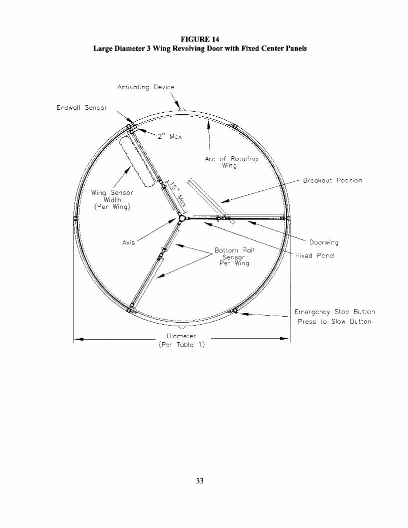
FIGURE 14Large Diameter 3 Wing Revolving Door with Fixed Center Panels
Activating Device
Diameter(Per Table 1)
Breakout Position
Doorwing
Fixed Panel
Emergency Stop Button
Press to Slow Button
III
II
Bottom RoilSensor
Per Wing "III
II
II
II
II
II
II
II
/////
.;/,,""
.................... ",.
l---------------------,
Arc of Rotating \Wing \
"\,\
2" Max
....... --
Wing SensorWidth
(Per Wing)
...
Endwall Sensor
33
ADDITIONAL APPENDIX INFORMATION
Installation Automatic revolving doors should be adjusted by factory authorized installers before placinginto operation.Glass "signage" Some type of marking on the enclosure when glass is used.Acceptable Door RPM (Automatic) A walk speed on feet (915mm)per second was used to calculateacceptable door RPM in automatic doors in this Standard. This is more conservative than the building coderequirements in affect at the time ofpublication.Acceptable Door RPM (Manual) RPM for manual doors coincides with the building code requirements inaffect at the time ofpublication, which were based on a walk speed of 4 feet (l220mm) per second.
Recommended Maintenance and Inspection
The manufacturer should provide an owner's manual with the sale ofeach operator to explain how the ownershould perform regular safety checks.
Revolving doors require periodic maintenance and inspection to ensure compliance with this standard. It is stronglyrecommended that they are inspected at the time of installation and at a minimum annually thereafter, by a qualifiedinspector. It is also recommended that the doors are maintained on a regular basis by a qualified professional perthe manufacturer's instructions. Compliance to the current standards at the time of service is encouraged.
The qualified inspector should attend a one day educational seminar held by the manufacturer or an acceptedindustry organization.
General Information
Automatic revolving doors are widely used because they are energy efficient and can provide a secure entrance. Asthe industry has grown there became a need to have them covered by a standard.
The information and requirements in the standard are what is considered the best practice in the industry. Someowners may have the need to deviate from the standard to meet certain needs. The owner wanting high security ina building selects a card access security automatic revolving door but has need for a higher throughput on shiftchanges and might need to increase the RPM slightly above the limit shown.
One might desire slightly larger diameter revolving doors to move large objects or need a smaller diameter thanshown because of limited space. In case ofthe smaller diameter a wing sensor may not be able to be fully functionalor compliant.
Not meeting all requirements does not mean that the door is unsafe. It is important that a risk assessment be takenand offset with clear instructions to users with signage, good lighting, straight on approach, and uncrowded spacearound the door to allow easy exit to clear the door to offset any deviation.
Trained traffic is exempt by the standard. But the owner is encouraged to attempt to comply. In majority ofcasesall features required by the standard should be able to be met with perhaps only a small deviation.
Specifiers and owners are encouraged to give handicap and slow walking persons an alternative. One ofthealternatives in the standard is the push to slow feature on the door. Another is to place and automatic slide or swingdoor adjacent to the revolving door for their use. It is likely that the exit code will require an out swing dooradjacent to the revolving door and adding automation gives the user an extra benefit.
34