Embed Size (px)
Citation preview

SECTION 2
AMERICANPipe Joints

2-1
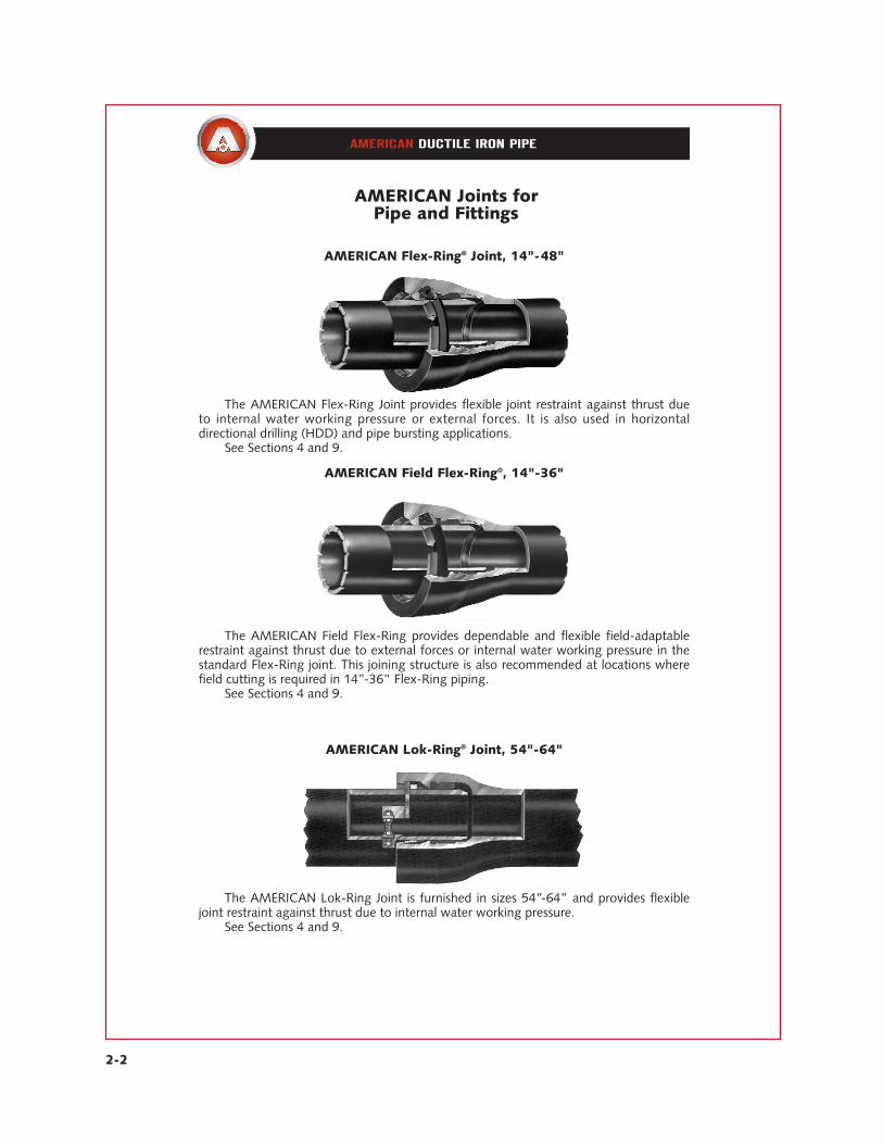
AMERICAN Joints forPipe and Fittings
AMERICAN Fastite® Joint, 4"-64"
The AMERICAN Fastite Joint, furnished in sizes 4”-64”, is a flexible, rubber ringcompression-type joint used extensively in underground service.
See pages 2-6 through 2-15 and Sections 3, 4, 7 and 9.
AMERICAN Flex-Ring® Joint, 4"-12"
AMERICAN Fastite® Joint with Fast-Grip® Gasket, 4"-30"
The AMERICAN Flex-Ring Joint provides flexible joint restraint against thrust dueto internal water working pressure or external forces. It is also used in horizontal directional drilling (HDD) and pipe bursting applications.
See Sections 4 and 9.
The AMERICAN Fast-Grip Gasket furnished in sizes 4”-30” provides flexible, field-adaptable joint restraint in a standard AMERICAN Fastite (or Flex-Ring) Bell.
See Sections 4 and 9.
2-2
AMERICAN Joints forPipe and Fittings
AMERICAN Lok-Ring® Joint, 54"-64"
The AMERICAN Lok-Ring Joint is furnished in sizes 54”-64” and provides flexiblejoint restraint against thrust due to internal water working pressure.
See Sections 4 and 9.
The AMERICAN Field Flex-Ring provides dependable and flexible field-adaptablerestraint against thrust due to external forces or internal water working pressure in thestandard Flex-Ring joint. This joining structure is also recommended at locations wherefield cutting is required in 14”-36” Flex-Ring piping.
See Sections 4 and 9.
AMERICAN Field Flex-Ring®, 14"-36"
The AMERICAN Flex-Ring Joint provides flexible joint restraint against thrust dueto internal water working pressure or external forces. It is also used in horizontal directional drilling (HDD) and pipe bursting applications.
See Sections 4 and 9.
AMERICAN Flex-Ring® Joint, 14"-48"

2-3
AMERICAN MJ Coupled Joint, 4"-48"
The AMERICAN MJ Coupled Joint is furnished in sizes 4”-48” and is an adaptationof the standard Mechanical Joint to provide joint restraint against thrust due to internalpressure.
See Section 9.
AMERICAN Joints forPipe and Fittings
The AMERICAN Mechanical Joint, furnished in pipe sizes 4”-12” and in fittingssizes 4”-48”, is a flexible stuffing box type connection used primarily in undergroundservice.
See pages 2-16 through 2-21 and Sections 3, 5, 7 and 9.
AMERICAN Mechanical Joint, 4"-48"
AMERICAN Flanged Joint, 4"-64"
The AMERICAN Flanged Joint, furnished in sizes 4”-64”, is widely used forexposed plant piping. In combination with other joints and with AMERICAN’s recom-mended NSF 61 certified Toruseal
®gasket, it is also commonly used for Long Span
installations.See Sections 6, 7 and 8.
2-4
AMERICAN Joints forPipe and Fittings
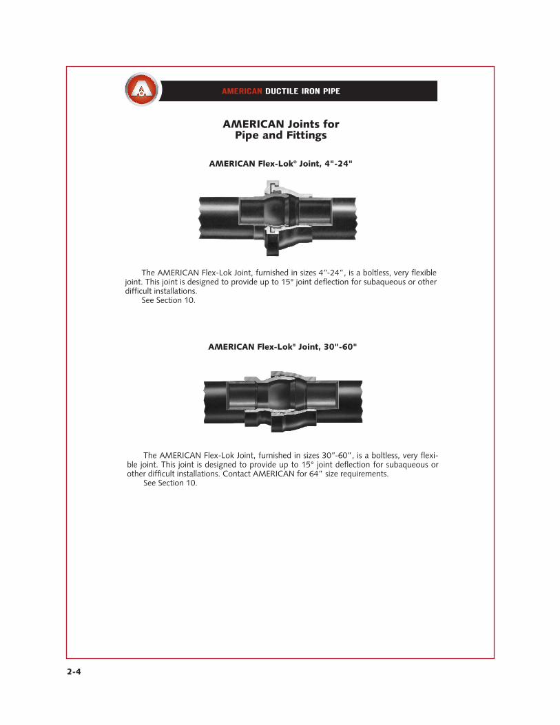
AMERICAN Flex-Lok® Joint, 4"-24"
AMERICAN Flex-Lok® Joint, 30"-60"
The AMERICAN Flex-Lok Joint, furnished in sizes 4”-24”, is a boltless, very flexiblejoint. This joint is designed to provide up to 15° joint deflection for subaqueous or otherdifficult installations.
See Section 10.
The AMERICAN Flex-Lok Joint, furnished in sizes 30”-60”, is a boltless, very flexi-ble joint. This joint is designed to provide up to 15° joint deflection for subaqueous orother difficult installations. Contact AMERICAN for 64” size requirements.
See Section 10.

2-5
AMERICAN Joints forPipe and Fittings
AMERICAN Fastite Joint Push-Bar pipe, furnished in sizes 4”-64”, allows theAMERICAN Fastite Joint to be used in trenchless installations using direct jacking orpushing (including high load installations such as microtunneling and some pipe burst-ing applications). See Section 7.
AMERICAN Fastite® Joint Push-Bar™ Pipe, 4"-64"
The AMERICAN Grooved Joint pictured above—and to a limited extent theShouldered Joint (not pictured)—are furnished for some plant piping installations.
See Section 2.
AMERICAN Grooved and Shouldered Joint, 4"-64"

2-6
AMERICAN Fastite Joint Pipe in sizes 4”-64” for water, sewage or other liquids has theproven long-life and high-strength qualitiesinherent in pipe produced centrifugally inaccordance with AWWA C151. In addition,this significant AMERICAN development, adependable, single gasket, push-on type jointmeeting the requirements of AWWA C111,affords the customer lower joint cost andtime-saving advantages in installation. It pro-vides exceptional strength and flexibility andhas been widely accepted by engineers, con-tractors and utility officials since the 1950s. Foradded flexibility during construction, and forpossible elimination of bends, a liberal 5°allowable deflection is standard in all sizesthrough 30”, offering 21” offset in a 20’length of pipe. Liberal deflection can also beprovided in larger diameter pipe with standardand Special Fastite Deflection Bells.
The patented AMERICAN Fastite Jointembodies many advanced design features andis rated for a water working pressure of 350 psi.For specific conditions, ductile iron piping withthis joint has been approved for much higherpressure conditions. The socket, which is scien-tifically designed with two gasket recesses and adividing buttress, is manufactured to close toler-ances so that the gasket is self-centered, securelyconfined, and firmly compressed for a perma-nent, tight, trouble-free joint. The Fastite jointseal, bubble-tight under vacuum and externalpressure, becomes even tighter with the appli-cation of internal pressure due to a speciallydesigned wedging surface in the socket.
Fastite Joint AssemblyThe bell opening is slightly tapered to
provide easy entry of the pipe end; the flaredsocket design permits liberal joint deflection.
The plain end of the pipe is tapered or roundedto facilitate entry into the bell and self-centeringin the gasket. On pipe cut in the field, theplain end can be easily beveled and smoothedby the use of a portable grinding wheel orother suitable apparatus. Methods of cuttingductile iron pipe are described in Section 3.
A stripe is painted on the plain end ofAMERICAN Fastite Joint Pipe to provide avisual means of checking the joint alignmentand to assure proper insertion. See page 2-10for detailed assembly instructions.
Fastite GasketThe Fastite Joint sealing component—a
molded synthetic rubber ring gasket of twohardnesses, shaped to fit the configuration ofthe gasket socket—is manufactured per allrequirements of ANSI/AWWA C111/A21.11and under AMERICAN’s own rigid specifica-tions, assuring closely controlled dimensionaland hardness properties. The smaller end ofthe gasket is of harder rubber, approximately85 durometer hardness, which provides astrong shoulder for self-centering on the gas-ket buttress, a permanent seal against coldflow, and protection from deterioration. Thelarger end of the gasket is of softer rubber,approximately 65 durometer hardness, provid-ing ease of assembly and positive sealing. Thedesign assures effective sealing at low or highpressures and in straight or deflected jointalignment. It also eliminates any concerns ofinfiltration or root intrusion, and assures posi-tive sealing against negative pressure, thuspreventing gasket “pullout” should a vacuumbe created in the line.
A taper on the inside of the gasket allowsthe entering pipe to locate and center on thehard section and reduces friction loads during
AMERICAN Fastite® Joint PipeFor Water, Sewage or Other Liquids
2-7
subsequent assembly. The snug fit and thehard section of the gasket, in conjunction withthe design of the buttress, act to restrain thegasket against dislodgment during assembly.Additional internal pressure results in increasedtightness of the seal when pipe is either instraight alignment or deflected.
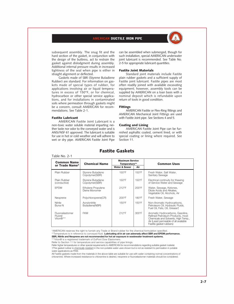
Gaskets made of SBR (Styrene ButadieneRubber) are standard. For information on gas-kets made of special types of rubber, forapplications involving air or liquid tempera-tures in excess of 150°F, or for chemical,hydrocarbon or other special service applica-tions, and for installations in contaminatedsoils where permeation through gaskets mightbe a concern, consult AMERICAN for recom-mendations. See Table 2-1.
Fastite LubricantAMERICAN Fastite Joint Lubricant is a
non-toxic water soluble material imparting nei-ther taste nor odor to the conveyed water and isANSI/NSF 61 approved. The lubricant is suitablefor use in hot or cold weather and will adhere towet or dry pipe. AMERICAN Fastite Joint Pipe
can be assembled when submerged, though forsuch installation, special AMERICAN underwaterjoint lubricant is recommended. See Table No.2-5 for appropriate lubricant quantities.
Fastite Joint MaterialsStandard joint materials include Fastite
plain rubber gaskets and a sufficient supply ofFastite joint lubricant. Fastite pipes are mostoften readily joined with available excavatingequipment; however, assembly tools can besupplied by AMERICAN on a loan basis with anominal deposit which is refundable uponreturn of tools in good condition.
FittingsAMERICAN Fastite or Flex-Ring fittings and
AMERICAN Mechanical Joint Fittings are usedwith Fastite Joint pipe. See Sections 4 and 5.
Coating and LiningAMERICAN Fastite Joint Pipe can be fur-
nished asphaltic coated, cement lined, or withspecial coating or lining where required. SeeSection 11.
Fastite Gaskets
Plain Rubber Styrene Butadiene 150°F 150°F Fresh Water, Salt Water, Copolymer(SBR) Sanitary Sewage
Plain Rubber Styrene Butadiene 150°F 150°F Electrical continuity for thawing(conductive) Copolymer(SBR) of Service Water and Sewage
EPDM Ethylene Propylene 212°F 200°F Water, Sewage, Ketones, Diene Monomer Dilute Acids and Alkalies,
Vegetable Oil, Alcohols, Air
Neoprene Polychloroprene(CR) 200°F 180°F Fresh Water, Sewage
Nitrile Acrylonitrile 150°F 150°F Non-Aromatic Hydrocarbons,Buna-N Butadiene(NBR) Petroleum Oil, Hydraulic Fluids,
Fuel Oil, Fats, Oil, Grease†
Fluoroelastomer FKM 212°F 300°F Aromatic Hydrocarbons, Gasoline,Fluorel Refined Petroleum Products, mostViton®*** Chemicals and Solvents, High Temp.,
Air (Least permeable of all available Fastite gasket rubbers)
Table No. 2-1
Common Nameor Trade Name* Chemical Name
Maximum ServiceTemperature**
Water & Sewer AirCommon Uses
*AMERICAN reserves the right to furnish any Trade or Brand rubber for the chemical formulation specified.**Temperature is in reference to conveyed fluid. Lubricating oil in air can adversely affect SBR and EPDM performance.SBR, Nitrile and Neoprene are not recommended for hot air exposure in wastewater treatment systems.***Viton® is a registered trademark of DuPont Dow Elastomers.Refer to Section 11 for temperature and service capabilities of pipe linings.Refer higher temperatures or other special requirements to AMERICAN for recommendations regarding suitable gasket material.†This gasket rubber is chemically resistant in the non-potable water uses shown but is not as resistant to permeation in potablewater applications as FKM.All Fastite gaskets made from the materials in the above table are suitable for use with water containing normal concentrations ofchloramine. Where increased resistance to chloramine is desired, neoprene or fluoroelastomer materials should be considered.

2-8
*Dimensions subject to change at our option. Check AMERICAN if exact dimensions required.See Section 3 for additional information on ductile iron pipe.See Sections 4 and 7 for information on Fastite fittings.
AMERICAN Fastite® Jointfor Ductile Iron PipeANSI/AWWA C111/A21.11
Standard Dimensions
LAYING LENGTHD
F* A
Table No. 2-2
16 20 6.90 3.38 8.6018 20 9.05 3.75 11.1610 20 11.10 3.75 13.2512 20 13.20 3.75 15.2214 20 15.30 5.23 17.7316 20 17.40 5.23 19.8618 20 19.50 5.50 22.16
24 20 25.80 5.50 28.5030 20 32.00 6.50 34.9536 20 38.30 6.50 41.3742 20 44.50 7.50 48.2748 20 50.80 8.00 54.7154 20 57.56 8.50 61.6560 20 61.61 8.75 65.8064 20 65.67 9.00 70.04
Sizein.
NominalLaying Length
ft. AOutside Diameter
DDepth of Socket
F*Bell O.D.
Dimensions in Inches
14 18 4.80 3.31 6.40
20 20 21.60 5.50 24.28
2-9
Table No. 2-4
4 3⁄8 6 9⁄16
8 3⁄4 10 15⁄16
12 11⁄8 14 15⁄16
16 11⁄2 18 15⁄8
24 21⁄4 30 23⁄4 36 25⁄8 42 21⁄4 48 21⁄2 54 27⁄8 60 31⁄8 64 33⁄8
20 17⁄8
S Separationin.
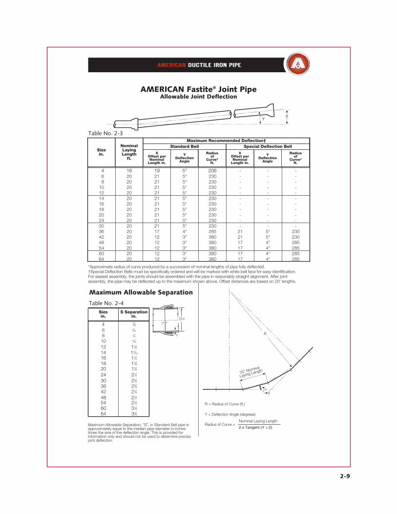
*Approximate radius of curve produced by a succession of nominal lengths of pipe fully deflected.†Special Deflection Bells must be specifically ordered and will be marked with white bell face for easy identification.For easiest assembly, the joints should be assembled with the pipe in reasonably straight alignment. After joint assembly, the pipe may be deflected up to the maximum shown above. Offset distances are based on 20' lengths.
AMERICAN Fastite® Joint PipeAllowable Joint Deflection
XY
Table No. 2-3
14 18 19 5° 206 - - - 16 20 21 5° 230 - - - 18 20 21 5° 230 - - - 10 20 21 5° 230 - - - 12 20 21 5° 230 - - - 14 20 21 5° 230 - - - 16 20 21 5° 230 - - - 18 20 21 5° 230 - - - 20 20 21 5° 230 - - - 24 20 21 5° 230 - - - 30 20 21 5° 230 - - - 36 20 17 4° 285 21 5° 230 42 20 12 3° 380 21 5° 230 48 20 12 3° 380 17 4° 285 54 20 12 3° 380 17 4° 285 60 20 12 3° 380 17 4° 285 64 20 12 3° 380 17 4° 285
Maximum Allowable Separation
Sizein.
R
Y
20' Nominal
Laying Length
[ [
[
[
[
R = Radius of Curve (ft.)
Y = Deflection Angle (degrees)
Radius of Curve =Nominal Laying Length
2 x Tangent (Y � 2)Maximum Allowable Separation, “S”, in Standard Bell pipe isapproximately equal to the median pipe diameter in inchestimes the sine of the deflection angle. This is provided forinformation only and should not be used to determine precisejoint deflection.
Sizein.
NominalLayingLength
ft.X
Offset perNominal
Length in.
Y Deflection
Angle
Radius of
Curve*ft.
XOffset perNominal
Length in.
Y Deflection
Angle
Radius of
Curve*ft.
Maximum Recommended Deflection†Standard Bell Special Deflection Bell
2 x Tangent (Y ÷ 2)
S
D-t
t
2-10
The AMERICAN Fastite Joint is a push-on type joint meeting al l the rigorousrequirements of AWWA C111. TheANSI/AWWA C600 Standard covers indetail the installation of ductile iron watermains, including assembly instructions forpush-on joint pipe.
Field-cutting of AMERICAN Ductile IronPipe can be easily performed, thus eliminat-ing the necessity for factory-made speciallengths of Fastite pipe. The plain end ofFastite pipe cut in the field requires little orno preparation for assembly into the socketof a mechanical joint fitting. Where a cutpipe is to be assembled into a Fastite socket,the required beveling or rounding of theplain end can be easily accomplished by theuse of a portable grinding wheel or othersuitable apparatus. Methods of cutting duc-tile iron pipe are described in Section 3.
The AMERICAN Fastite Joint requiresonly one joint component, the rubber gas-ket*, which when properly installed, fits snug-ly in the gasket recess in the bell socket. Aspecial lubricant supplied with the pipe isapplied to the plain end and the inside surfaceof the gasket before assembly. The pipe endis tapered or rounded to provide self-centeringof the plain end in the gasket and ease ofassembly. A circumferential stripe on the plainend provides a visual indication for checkingthe proper insertion of the joint. The stripe,shown in the photographs illustrating assem-bly methods, passes fully into the bell whenthe plain end is fully inserted into the socket
with the two lengths of pipe in straight alignment. Joints can then be safely deflectedup to the extent shown in Table No. 2-3. Indeflected joints, the stripe will typically be visi-ble to some extent after assembly.
Easier assembly is effected if the pipe issuspended an inch or so off the bottom ofthe trench during the jointing operation.
The following instructions should be fol-lowed in order to properly assemble the jointsand to fully realize the maximum speed andease of assembly of the Fastite Joint:
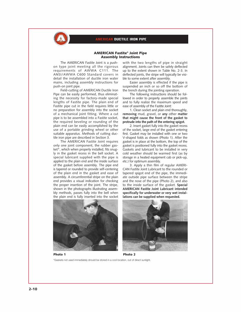
1. Clean socket and plain end thoroughly,removing mud, gravel, or any other matterthat might cause the front of the gasket toprotrude into the path of the entering spigot.
2. Insert gasket fully into the gasket recessof the socket, large end of the gasket enteringfirst. Gasket may be installed with one or twoV-shaped folds as shown (Photo 1). After thegasket is in place at the bottom, the top of thegasket is positioned fully into the gasket recess.Gaskets and lubricant to be installed in verycold weather should be warmed first (as bystorage in a heated equipment cab or pick-up,etc.) for optimum assembly.
3. Apply a thin film of regular AMERI-CAN Fastite Joint Lubricant to the rounded ortapered spigot end of the pipe, the immedi-ate outside pipe surface between the stripeand the nose of the pipe (Photo 2), and alsoto the inside surface of the gasket. SpecialAMERICAN Fastite Joint Lubricant intendedspecifically for underwater or very wet instal-lations can be supplied when requested.
AMERICAN Fastite® Joint PipeAssembly Instructions
Photo 1 Photo 2
*Gaskets not used immediately should be stored in a cool location, out of direct sunlight.

2-11
Caution: If a spigot end contacts theground or trench side after lubrication, anyadhering dirt or rocks should be cleaned offand the area re-lubricated prior to assembly.
4. Insert the plain end in the socket. Foroptimum assembly it is preferable that theentering pipe be in reasonably straight align-ment; however, the Fastite Joint may beassembled if necessary with the pipe deflect-ed within its rated deflection. (Exception: IfFast-Grip gaskets are being used, straightalignment must be maintained.) Push theplain end into the socket using any of theapplicable assembly methods describedhereinafter. If the joint cannot be assembledwith a moderate force, remove the pipe andcheck for the cause of the difficulty, such asimproper positioning of gasket, insufficientor wrong type lubricant, dirt under or behindthe gasket, dirt adhering to the pipe, or anyother cause which would result in obstruc-tion or increased friction between pipe end
and gasket surface. For assurance of properassembly, a thin automotive, blade-typefeeler gauge can also be used if desired forquick and easy probe confirmation of cor-rectly installed axial gasket position aroundthe joint.
5. “Backwards” installation. AMERICANdoes not recommend “backward laying”(bells assembled over spigots, rather thanspigots inserted into bells as pictured in thisliterature) of large-diameter ductile iron pipein buried installations. AMERICAN can furnishbell and plain end fittings to minimize theneed for backward pipe laying. Otherdevices such as sleeves and couplings mayalso be employed for this reason. However,if this condition cannot be avoided, westrongly recommend that installers contactAMERICAN for instructions on how to reducethe potential for problems that could occurwhen assembling pipe in this manner.
In general, Fastite joints or other Fastitegasketed pipes may be readily pushed orpulled together without the need for com-plicated tools or substantial manpower. Thisis most often accomplished with the proce-dures discussed on page 2-14. In general,the joints of AMERICAN push-on pipes arepurposefully “tight,” and most joints requirean assembly force of about 100 to 200pounds or more of assembly force per inchof pipe diameter (i.e. a 12" joint mightrequire about 12 x 100 or 1,200 pounds ofassembly force).
In pulling operations, simply wrap asound wire rope choker cable or nylon slingaround the barrel of the entering pipe.Secure the thimble eye or other end loop ofthe choker to a suitably anchored pullingdevice (e.g. backhoe, come-along, etc.).Use the mechanism to pull the cable taut in
the assembly direction (Photo 3). Continuepulling the cable in a smooth, continuousmotion until the joint is in the fully assembledposition. If desired for special conditions,AMERICAN can furnish suitable, simplecome-alongs and choker cables for man-
Photo 3
AMERICAN Pipe Assembly Mechanisms
2-12
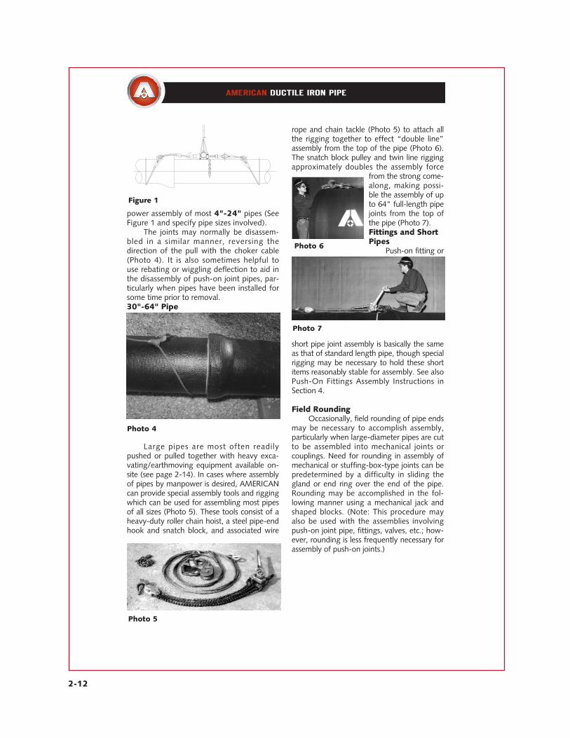
power assembly of most 4"-24" pipes (SeeFigure 1 and specify pipe sizes involved).
The joints may normally be disassem-bled in a similar manner, reversing thedirection of the pull with the choker cable(Photo 4). It is also sometimes helpful touse rebating or wiggling deflection to aid inthe disassembly of push-on joint pipes, par-ticularly when pipes have been installed forsome time prior to removal.30"-64" Pipe
Large pipes are most often readilypushed or pulled together with heavy exca-vating/earthmoving equipment available on-site (see page 2-14). In cases where assemblyof pipes by manpower is desired, AMERICANcan provide special assembly tools and riggingwhich can be used for assembling most pipesof all sizes (Photo 5). These tools consist of aheavy-duty roller chain hoist, a steel pipe-endhook and snatch block, and associated wire
rope and chain tackle (Photo 5) to attach allthe rigging together to effect “double line”assembly from the top of the pipe (Photo 6).The snatch block pulley and twin line riggingapproximately doubles the assembly force
from the strong come-along, making possi-ble the assembly of upto 64" full-length pipejoints from the top ofthe pipe (Photo 7).Fittings and ShortPipes
Push-on fitting or
short pipe joint assembly is basically the sameas that of standard length pipe, though specialrigging may be necessary to hold these shortitems reasonably stable for assembly. See alsoPush-On Fittings Assembly Instructions inSection 4.
Field RoundingOccasionally, field rounding of pipe ends
may be necessary to accomplish assembly,particularly when large-diameter pipes are cutto be assembled into mechanical joints orcouplings. Need for rounding in assembly ofmechanical or stuffing-box-type joints can bepredetermined by a difficulty in sliding thegland or end ring over the end of the pipe.Rounding may be accomplished in the fol-lowing manner using a mechanical jack andshaped blocks. (Note: This procedure mayalso be used with the assemblies involvingpush-on joint pipe, fittings, valves, etc.; how-ever, rounding is less frequently necessary forassembly of push-on joints.)
Photo 5
Photo 6
Photo 7
Photo 4
Figure 1
2-13
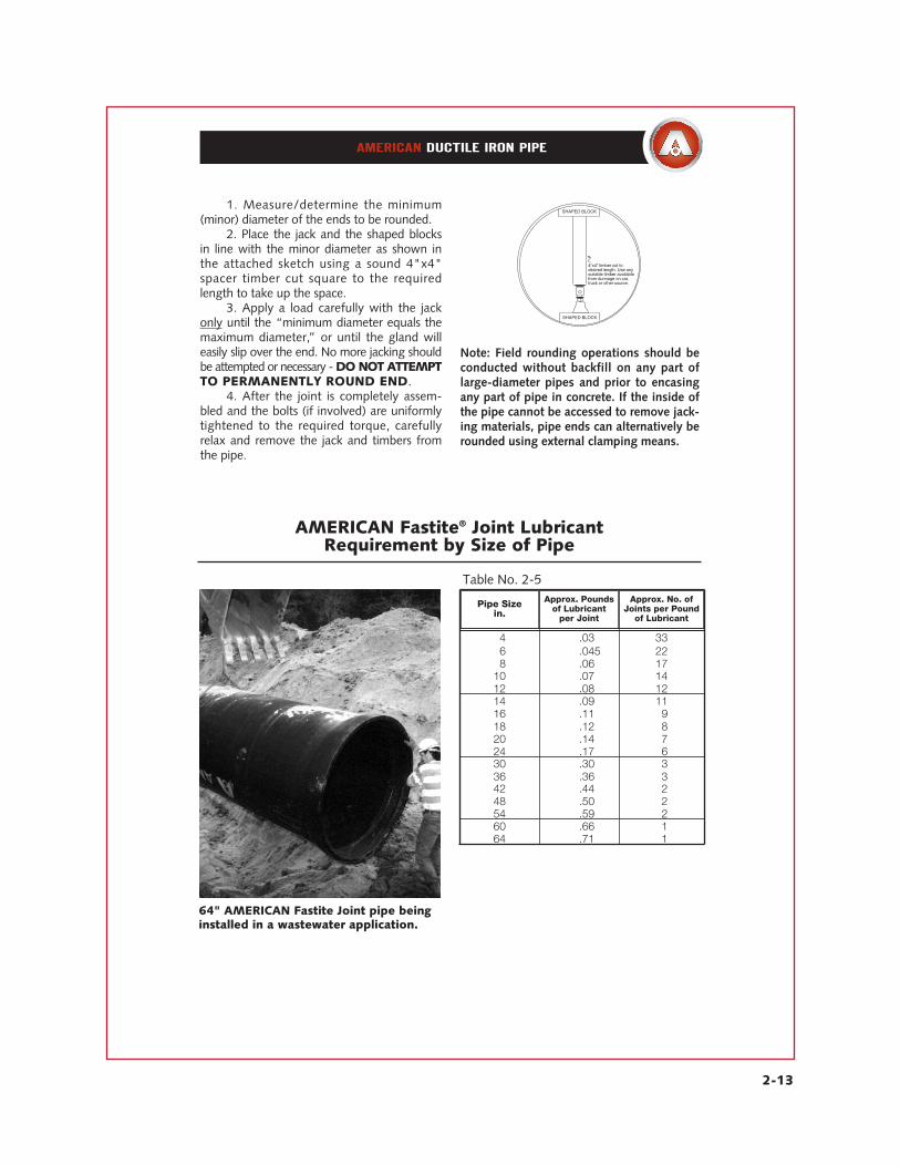
AMERICAN Fastite® Joint Lubricant Requirement by Size of Pipe
Table No. 2-5
14 .03 33 16 .045 22 18 .06 17 10 .07 14 12 .08 12 14 .09 11 16 .11 19 18 .12 18 20 .14 17 24 .17 16 30 .30 13 36 .36 13 42 .44 12 48 .50 12 54 .59 12 60 .66 11 64 .71 11
Pipe Sizein.
Approx. Poundsof Lubricant
per Joint
Approx. No. ofJoints per Pound
of Lubricant
64" AMERICAN Fastite Joint pipe beinginstalled in a wastewater application.
Note: Field rounding operations should beconducted without backfill on any part oflarge-diameter pipes and prior to encasing any part of pipe in concrete. If the inside ofthe pipe cannot be accessed to remove jack-ing materials, pipe ends can alternatively berounded using external clamping means.
1. Measure/determine the minimum(minor) diameter of the ends to be rounded.
2. Place the jack and the shaped blocksin line with the minor diameter as shown inthe attached sketch using a sound 4"x4"spacer timber cut square to the requiredlength to take up the space.
3. Apply a load carefully with the jackonly until the “minimum diameter equals themaximum diameter,” or until the gland willeasily slip over the end. No more jacking shouldbe attempted or necessary - DO NOT ATTEMPTTO PERMANENTLY ROUND END.
4. After the joint is completely assem-bled and the bolts (if involved) are uniformlytightened to the required torque, carefullyrelax and remove the jack and timbers fromthe pipe.
SHAPED BLOCK
SHAPED BLOCK
4"x4" timber cut todesired length. Use anysuitable timber availablefrom dunnage on car,truck or other source.

2-14
Spade or Crowbar MethodThis is applicable to the smaller sizes
of AMERICAN Fastite Joint Pipe, and con-sists of centering the lubricated end of theentering pipe in the gasket and thenpushing against the bell face of the enter-ing pipe with a spade or crowbar driveninto the ground in front of the bell face.This method requires the trench bottomto be fairly firm soil. The method may notbe effective in a rocky trench or with atrench that is soft, muddy or sandy. Awooden block between the bell face andthe pry bar may increase the leverage.Easier assembly is effected if the pipe issuspended an inch or so off the bottom ofthe trench.
Backhoe and Heavy EquipmentMethods
These methods are usually applicableto the intermediate and larger sizes ofAMERICAN Fastite Joint Pipe where thebar method might not be effective. Itconsists of centering the end of the enter-ing pipe in the gasket as the pipe to beassembled is suspended from the back-hoe. Then it can be pulled into the adjoin-ing socket with the pipe sling by movingthe backhoe arm toward the previouslyassembled pipe. In other instances, thepipe may be assembled by placing thebackhoe or other earth mover bucket orblade against the bell face of the enteringpipe and pushing it into the socket. Whenpushing against the bell face, care shouldbe taken to avoid very small contact areasand possible damage to the pipe bells orspigots. Wood cushions between thebackhoe bucket and the pipe are particu-larly effective in preventing damage.
AMERICAN Fastite® JointCommon Assembly Methods
In seeking ways to take even greater advantage of the cost-reducing features ofthe Fastite Joint, utility contractors have developed other methods of assembling thisjoint without special tools. The following methods are described for the information ofthe user, who may elect to use them at his discretion, keeping in mind that these meth-ods may not be effective for all installations and under all field conditions.
Spade or Crowbar Method
Backhoe and Heavy Equipment Methods
2-15
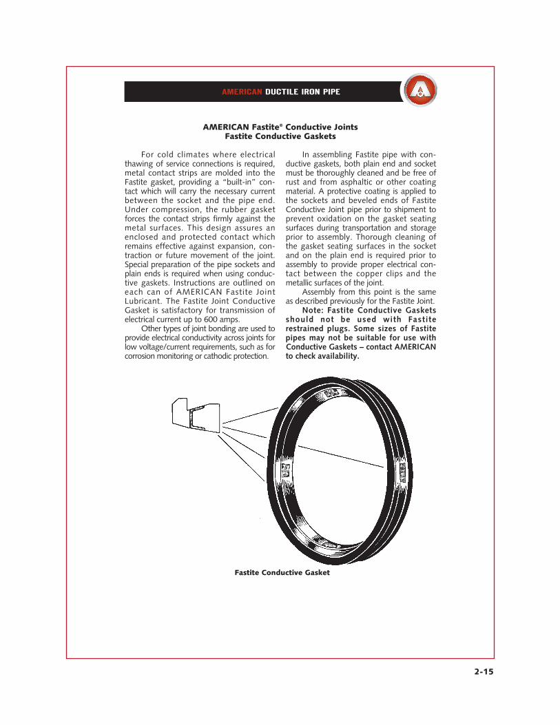
For cold climates where electricalthawing of service connections is required,metal contact strips are molded into theFastite gasket, providing a “built-in” con-tact which will carry the necessary currentbetween the socket and the pipe end.Under compression, the rubber gasketforces the contact strips firmly against themetal surfaces. This design assures anenclosed and protected contact whichremains effective against expansion, con-traction or future movement of the joint.Special preparation of the pipe sockets andplain ends is required when using conduc-tive gaskets. Instructions are outlined oneach can of AMERICAN Fastite JointLubricant. The Fastite Joint ConductiveGasket is satisfactory for transmission ofelectrical current up to 600 amps.
Other types of joint bonding are used toprovide electrical conductivity across joints forlow voltage/current requirements, such as forcorrosion monitoring or cathodic protection.
In assembling Fastite pipe with con-ductive gaskets, both plain end and socketmust be thoroughly cleaned and be free ofrust and from asphaltic or other coatingmaterial. A protective coating is applied tothe sockets and beveled ends of FastiteConductive Joint pipe prior to shipment toprevent oxidation on the gasket seatingsurfaces during transportation and storageprior to assembly. Thorough cleaning ofthe gasket seating surfaces in the socketand on the plain end is required prior toassembly to provide proper electrical con-tact between the copper clips and themetallic surfaces of the joint.
Assembly from this point is the sameas described previously for the Fastite Joint.
Note: Fastite Conductive Gasketsshould not be used with Fastiterestrained plugs. Some sizes of Fastitepipes may not be suitable for use withConductive Gaskets – contact AMERICANto check availability.
AMERICAN Fastite® Conductive JointsFastite Conductive Gaskets
Fastite Conductive Gasket

2-16
The AMERICAN Mechanical Jointwas developed by the American Cast IronPipe Company and first marketed in 1929.Since that time, millions of feet of AMERI-CAN pipe equipped with this joint havebeen installed to give dependable serviceacross the nation and in many foreigncountries. The joint is designed with astuffing box into which a rubber gasket iscompressed by a ductile iron gland drawnup with low-alloy steel bolts. It affords lib-eral deflection and allows expansion andcontraction of the line without leakage. Itis rated for a water working pressure ofup to 350 psi.
Originally designed to meet the rigidrequirements of the gas industry for apressure-tight joint, the AMERICANMechanical Joint was instrumental instarting a nationwide trend toward rub-ber-packed joints for water service as wellas gas service. Its design was widelyaccepted and it soon became the stan-dardized mechanical joint of the cast ironpipe industry.
The popularity of the AMERICANMechanical Joint among utility officials,contractors and engineers steadilyincreased until the majority of cast ironpiping furnished for gas, water, sewageand other services was equipped with thisjoint. However, push-on joint pipes, whichare less labor intensive and reliant withpush-on or mechanical joint fittings, cur-rently make up the vast majority of ductileiron pipelines being installed for under-ground service. Mechanical joint pipe isnow used to a much lesser extent.
The AMERICAN Mechanical Jointmeets the requirements of ANSI/AWWAC110/A21.10 and ANSI/AWWAC111/A21.11.
AMERICAN Ductile Iron MechanicalJoint Pipe is centrifugally cast in nominal 18’or 20’ laying lengths, depending on size,under rigid production and quality controlprocedures in accordance with ANSI/AWWAStandards. AMERICAN Mechanical JointDuctile Iron Pipe is produced in 4”-12” sizesand in Special Thickness Class 53 only.
AMERICAN Mechanical Joint PipeFor Water, Sewage or Other Liquids
2-17
The AMERICAN Mechanical Jointprovides easy installation under the mostadverse conditions. Plain rubber gasketsof SBR are normally used for water anddomestic sewage service. Fabric tippedplain rubber gaskets are available, as wellas other special gaskets such as oil-resis-tant rubber. Plain rubber gaskets ortipped gaskets are used for air or liquidtemperatures up to 120°F. For applica-tions involving temperatures in excess of120°F, or for other special service appli-
cations, and for installations in contami-nated soils where permeation throughgaskets might be a concern, consultAMERICAN for recommendations. SeeTable No. 2-6.
Standard joint accessories furnishedwith mechanical joint pipe and fittingsinclude ductile iron glands, low-alloy steeltee head bolts with hex nuts and plainrubber gaskets. The cost of these acces-sories is normally included in the priceof the pipe or fittings.
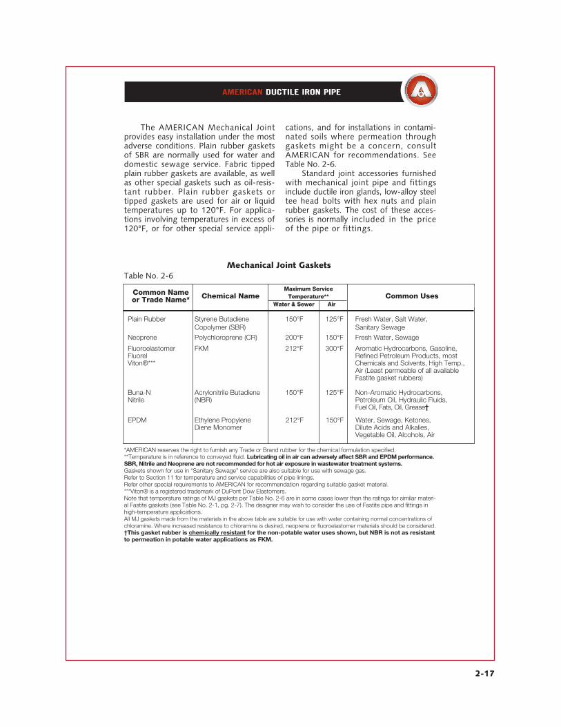
*AMERICAN reserves the right to furnish any Trade or Brand rubber for the chemical formulation specified.**Temperature is in reference to conveyed fluid. Lubricating oil in air can adversely affect SBR and EPDM performance.SBR, Nitrile and Neoprene are not recommended for hot air exposure in wastewater treatment systems.Gaskets shown for use in “Sanitary Sewage” service are also suitable for use with sewage gas.Refer to Section 11 for temperature and service capabilities of pipe linings.Refer other special requirements to AMERICAN for recommendation regarding suitable gasket material.***Viton® is a registered trademark of DuPont Dow Elastomers.Note that temperature ratings of MJ gaskets per Table No. 2-6 are in some cases lower than the ratings for similar materi-al Fastite gaskets (see Table No. 2-1, pg. 2-7). The designer may wish to consider the use of Fastite pipe and fittings inhigh-temperature applications.All MJ gaskets made from the materials in the above table are suitable for use with water containing normal concentrations ofchloramine. Where increased resistance to chloramine is desired, neoprene or fluoroelastomer materials should be considered.†This gasket rubber is chemically resistant for the non-potable water uses shown, but NBR is not as resistantto permeation in potable water applications as FKM.
Mechanical Joint Gaskets
Plain Rubber Styrene Butadiene 150°F 125°F Fresh Water, Salt Water, Copolymer (SBR) Sanitary Sewage
Neoprene Polychloroprene (CR) 200°F 150°F Fresh Water, Sewage
Fluoroelastomer FKM 212°F 300°F Aromatic Hydrocarbons, Gasoline,Fluorel Refined Petroleum Products, mostViton®*** Chemicals and Solvents, High Temp.,
Air (Least permeable of all availableFastite gasket rubbers)
Buna-N Acrylonitrile Butadiene 150°F 125°F Non-Aromatic Hydrocarbons, Nitrile (NBR) Petroleum Oil, Hydraulic Fluids,
Fuel Oil, Fats, Oil, Grease†
EPDM Ethylene Propylene 212°F 150°F Water, Sewage, Ketones, Diene Monomer Dilute Acids and Alkalies,
Vegetable Oil, Alcohols, Air
Common Nameor Trade Name* Chemical Name
Maximum ServiceTemperature**
Water & Sewer AirCommon Uses
Table No. 2-6

2-18
AM
ER
ICA
N M
echan
ical
Join
tA
NSI/
AW
WA
C111/A
21.1
1 Sta
ndar
d D
imen
sions
14"-
48"
Gla
nds
may
be
tape
red
as s
how
n by
dot
ted
line
LM
0.19
"
JA
K2
K1
B
S
F
Tabl
e N
o. 2
-7
* 2
2.5
0
2.
50
2.
61
4.
75
6.
00
6.
25
6.
25
.
56
.
75
.
62
.3
7
.44
* 21 ⁄4
2.75
2.50
2.86
5.00
6.25
6.50
6.50
.56
.75
.62
.37
.4
4
*
3
3
.96
2.50
4.06
6.19
7.62
7.69
7.69
.87
.94
.62
.40
.5
2
14
4.8
0
2.
50
4.
90
7.
50
9.
06
9.
38
9.
12
.
91
1.
00
.
75
.4
1
.65
16
6
.90
2.50
7.00
9.50
1
1.06
1
1.31
1
1.12
.94
1.06
.88
.43
.7
0
18
9.0
5
2.
50
9.
15
11.
75
13.
31
13.
63
13.
37
.
98
1.
12
1.
00
.4
5
.75
10
11
.10
2.50
1
1.20
1
4.00
1
5.62
1
5.81
1
5.62
.98
1.19
1.00
.47
.8
0
12
13.2
0
2.
50
13.
30
16.
25
17.
88
18.
06
17.
88
.
98
1.
25
1.
00
.4
9
.85
14
15
.30
3.50
1
5.44
1
8.75
2
0.25
2
0.69
2
0.25
1.02
1.31
1.25
.51
.8
9
16
17.4
0
3.
50
17.
54
21.
00
22.
50
22.
94
22.
50
1.
08
1.
38
1.
31
.5
2
.97
18
19
.50
3.50
1
9.64
2
3.25
2
4.75
2
5.28
2
4.75
1.14
1.44
1.38
.53
1.0
5
20
21.6
0
3.
50
21.
74
25.
50
27.
00
27.
08
27.
00
1.
20
1.
50
1.
44
.5
4
1
.12
24
25
.80
3.50
2
5.94
3
0.00
3
1.50
3
1.75
3
1.50
1.26
1.62
1.56
.56
1.2
2
30
32.0
0
4.
00
32.
17
36.
88
**
39.
12
39.
12
**
1
.81
2.00
**
1.5
0
36
38.3
0
4.
00
38.
47
43.
75
**
46.
00
46.
00
**
2
.00
2.00
**
1.8
0
42
44.5
0
4.
00
44.
67
50.
62
**
53.
12
53.
12
**
2
.00
2.00
**
1.9
5
48
50.8
0
4.
00
50.
97
57.
50
**
60.
00
60.
00
**
2
.00
2.00
**
2.2
0
Siz
ein
.A
Pla
in E
nd
BF
JC
entr
ifugal
Pip
eFit
tings
K2
Centr
ifugal
Pip
eFit
tings
MC
entr
ifugal
Pip
eFit
tings
Dim
ensi
ons
in Inches
K1
LS
*2",
21 ⁄4"
and
3"
size
s of
pip
e ar
e no
long
er m
anuf
actu
red
by A
ME
RIC
AN
and
dim
ensi
ons
are
give
n fo
r in
form
atio
n on
ly. 2
" an
d 2
1 ⁄4"
size
s ar
e no
t sho
wn
in A
WW
A C
111.
**14
"-48
" M
echa
nica
l Joi
nts
are
not a
vaila
ble
on c
entr
ifuga
l pip
e.Th
e du
ctile
iron
pip
e be
ll fla
nges
are
in a
ccor
danc
e w
ith A
WW
A C
111
whi
ch a
lso
prov
ides
that
thic
ker
bell
flang
es m
ay b
e fu
rnis
hed.
For
addi
tiona
l inf
orm
atio
n an
d to
lera
nces
see
AW
WA
C11
1.B
olt H
oles
are
1 ⁄8" la
rger
than
the
bolt
diam
eter
s. S
ee T
able
No.
2-8
.W
eigh
ts a
nd c
lass
es fo
r du
ctile
iron
pip
e ar
e gi
ven
in S
ectio
n 3.

2-19
Sizein.
AMERICAN no longer manufactures 2”, 21⁄4” and 3” sizes of pipe; bolts required per joint for 2” and 21⁄4” sizes were 25⁄8” x21⁄2”, and for 3” size were 45⁄8” x 3”.Bolts used with mechanical joint retainer glands may be required by the manufacturers of those devices to be longer thanshown above.When required and when used with bell flanges “tapped for studs,” stud bolts in lieu of Tee Head bolts are normallyordered of the same length of the Tee Head bolts they replace (See pages 2-24 and 2-25).†Gasket weights shown here are for standard SBR rubber; other available rubber types are shown on page 2-17.*14”-48” mechanical joints are for fittings only.**54” Mechanical Joints are used only with special mechanical joint sleeves. This size is not in AWWA C110.
AMERICAN Mechanical Joint Accessories
Table No. 2-8
4 14 3⁄4 x 31⁄2 113 116 .42 110 6 16 3⁄4 x 31⁄2 115 111 .59 117 8 16 3⁄4 x 41⁄2 115 118 .75 124 10 18 3⁄4 x 41⁄2 117 120 .92 128 12 18 3⁄4 x 41⁄2 117 130 1.09 139 14 10 3⁄4 x 41⁄2 119 135 1.23 146 16 12 3⁄4 x 41⁄2 111 145 1.42 158 18 12 3⁄4 x 41⁄2 111 155 1.56 168 20 14 3⁄4 x 41⁄2 113 170 1.77 185 24 16 3⁄4 x 51⁄2 115 190 2.13 108
30* 20 11⁄4 x 61⁄21⁄2 141 180 4.16 22536* 24 11⁄4 x 61⁄21⁄2 149 235 4.81 28942* 28 11⁄4 x 61⁄21⁄21⁄2 199 300 5.77 40548* 32 11⁄4 x 61⁄21⁄21⁄2 113 365 6.52 485
No. PerJoint
BoltsTotal Gland Gasket† One Set
AccessoriesSizein.
Gland
Gasket
Alloy Steel Tee Head Boltwith Hex Nut
54** 36 11⁄4 x 61⁄21⁄21⁄2 127 360 7.30 494
Weight in PoundsBolts

2-20
*Approximate radius of curve produced by a succession of nominal lengths of pipe fully deflected. A shorter radius can be obtained using shorter pipes.
The joint should be assembled with the pipe in reasonably straight alignment. Joint deflection to the maximum shownabove may be made after assembly but before tightening bolts. Offset distances are based on 20’ lengths.**14”-48” Mechanical Joints are provided on fittings and valves only.
XY
Table No. 2-9
14 18 31 8°-18’ 124 16 20 30 7°-07’ 160 18 20 22 5°-21’ 220 10 20 22 5°-21’ 220 12 20 22 5°-21’ 220 14 ** ** 3°-35’ ** 16 ** ** 3°-35’ ** 18 ** ** 3°-00’ ** 20 ** ** 3°-00’ ** 24 ** ** 2°-23’ ** 30 ** ** 2°-23’ ** 36 ** ** 2°-05’ ** 42 ** ** 2°-00’ ** 48 ** ** 2°-00’ **
Sizein.
Nominal Laying Length
ft.
XOffset per Nominal Length
in.
YDeflection
Angle
Radius of Curve*ft.
Maximum Recommended Deflection
Maximum Allowable Separation, “S”,is provided for information only andshould not be used to determineprecise joint deflection.
Maximum AllowableSeparation
S
Table No. 2-10
24 11 30 11⁄4 36 13⁄8 42 11⁄2 48 13⁄4
Sizein.
SSeparation
in.
R
Y
20' Nominal
Laying Length
[ [
[
[
[
R = Radius of Curve (ft.)
Y = Deflection Angle (degrees)
Radius of Curve =Nominal Laying Length
2 x Tangent (Y/2)
AMERICAN Mechanical Joint PipeAllowable Joint Deflection

2-21
1. Thoroughly clean socket and plainend of all rust or foreign material; slip thegland over plain end with the lip exten-sion toward plain end, followed by thegasket with thick section facing the gland.Gaskets to be installed during very coldweather should be warmed first.*
2. Lubricate socket, gasket andpla in end with soapy water or anapproved pipe lubr icant meet ingrequirements of AWWA C111.
3. Insert plain end into socket andpush gasket into position, making sure it isevenly seated in socket.
4. Slide gland into position, insertbolts and run nuts up finger-tight.
5. Tighten bolts to draw glandtoward the pipe flange evenly, maintain-ing approximately the same distancebetween the gland and the face of theflange at all points around the joint. Thismay be achieved by partially tighteningthe bottom bolt first; then the top bolt;next, the bolts at either side; and, finally,the remaining bolts. This process should
be repeated until all bolts are within therange of torques shown. In larger sizes(30”-48”), as many as 5 or morerepetitions may be required.
6. The completed joint.
It is recommended that the torque beapplied with torque-measuring wrenches.The approximate torque can be applied bya man trained to give an average pull on aspecific length regular ratchet wrench; for5⁄8” bolt, length of wrench is 8”; for 3⁄4”bolt, 10”; for 1” bolt, 14”; and for 11⁄4”bolt, 16”. Torque so applied shouldbe checked with torque-measuringwrenches. *Gaskets not usedimmediately should be stored in acool location, out of direct sunlight.
AMERICAN Mechanical Joint PipeAssembly Instructions
The AMERICAN Mechanical Joint is the Standardized Mechanical Joint per AWWAC111. Assembly of the Mechanical Joint is pictured and described below.
1 2 3
4 5 6
Table No. 2-11
4-24 3⁄4 75-9030-36 1 100-12042-48 11⁄4 120-150
Pipe Size†in.
Bolt Diameterin.
Range ofTorqueFt.-Lbs
† 14”-48” Mechanical Joints are provided on fittings and valves only.

2-22
DA
BR*
GR
OO
VE
DE
TAIL
O.D
.
T
C
Tabl
e N
o. 2
-12
*"R
" fo
r si
zes
4" a
nd 6
" is
.120
"; fo
r 8"
-12"
is .1
45";
for
14"
and
16"
is .1
65";
for
18"-
24"
is.1
85";
and
for
30"
and
36"
is .2
15".
**M
inim
um n
omin
al w
all t
hick
ness
of c
entri
fuga
lly c
ast d
uctil
e iro
n pi
pe fu
rnis
hed
with
Gro
oved
Join
t. Th
ickn
esse
s ab
ove
corr
espo
nd to
Spe
cial
Thi
ckne
ss C
lass
53
for 4
"-16
" di
amet
er, a
ndS
peci
al T
hick
ness
Cla
sses
54
and
55 fo
r dia
met
ers
18"
and
20",
resp
ectiv
ely,
and
Spe
cial
Thic
knes
s C
lass
56
for d
iam
eter
s 24
"-36
".†P
ress
ure
ratin
gs e
stab
lishe
d by
cou
plin
g m
anuf
actu
rer.
††M
axim
um le
ngth
for
4"si
ze is
17'
6", f
or 6
"-24
"si
zes
is 2
0'0"
, and
for
30"-
36"
size
s is
19'
6".
Sho
rter
leng
ths
than
the
max
imum
leng
ths
can,
of c
ours
e, b
e fu
rnis
hed.
†††3
0" a
nd 3
6" s
izes
are
not
incl
uded
in A
WW
A C
606.
For
tole
ranc
es s
ee A
WW
A C
606.
Sta
ndar
d fit
tings
are
ava
ilabl
e w
ith G
roov
ed J
oint
s an
d ar
e no
rmal
ly a
vaila
ble
only
with
rigi
d gr
oovi
ng.
Cou
plin
gs fo
r G
roov
ed J
oint
s m
ay b
e fu
rnis
hed
by A
ME
RIC
AN
but
are
not
of o
ur d
esig
n or
man
ufac
ture
. Che
ck A
ME
RIC
AN
for
deta
ils a
nd r
ecom
men
datio
ns.
14
4
.80
.32
500
.7
50
.8
40
.
375
4.5
63
.
096
.151
31 ⁄2
13.8
1241
16
6
.90
.34
400
.7
50
.8
40
.
375
6.6
56
.
100
.154
31 ⁄2
21.4
1430
18
9
.05
.36
400
.8
75
.9
50
.
500
8.7
81
.
104
.177
41 ⁄2
30.1
1600
10
11
.10
.38
350
.9
38
1.0
15
.
500
10.8
13
.
114
.186
41 ⁄2
39.2
1785
12
13
.20
.40
350
.9
38
1.0
15
.
500
12.9
06
.
117
.192
41 ⁄2
49.2
1985
14
15
.30
.42
250
.9
38
1.0
15
.
625
14.9
69
.
126
.206
41 ⁄4
60.1
1200
16
17
.40
.43
250
1.1
88
1.3
40
.
625
17.0
63
.
128
.208
51 ⁄2
70.1
1410
18
19
.50
.47
250
1.1
88
1.3
40
.
625
19.1
25
.
148
.228
51 ⁄2
86.0
1720
20
21
.60
.51
150
1.1
88
1.3
40
.
625
21.2
19
.
150
.230
51 ⁄2
1
03.4
2070
24
25
.80
.56
150
1.1
88
1.3
40
.
625
25.4
06
.
157
.237
51 ⁄2
1
35.9
2720
Siz
ein
.O
.D.
T**
Nom
inal
Wall
Thic
kness
Couplin
g
Max.
Work
ing
Pre
ssure
†psi
Fle
xible
Join
tR
igid
Join
tB
C
AD
Gro
ove
Depth
Min
.M
ax.
Per
Foot
(Wit
hout
Couplin
g)
Per
Max
imum
††
Length
Weig
ht
in P
ounds
Min
. Length
Gro
ove
d E
nd-
Gro
ove
d E
nd
Pip
ein
.
Dim
ensi
ons
in Inches
3
0†††
3
2.00
.63
150
1.3
75
1.6
25
.
750
31.5
50
.
195
---
61 ⁄2
1
90.0
3710
3
6 †††
3
8.30
.73
150
1.3
75
1.6
25
.
750
37.8
50
.
195
---
61 ⁄2
2
63.7
5140
AM
ER
ICA
N G
roove
d a
nd S
hould
ered
Join
tsA
MER
ICA
N G
roove
d J
oin
tA
WW
A C
606
2-23
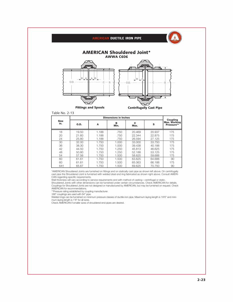
*AMERICAN Shouldered Joints are furnished on fittings and on statically cast pipe as shown left above. On centrifugallycast pipe the Shouldered Joint is furnished with welded steel end ring fabricated as shown right above. Consult AMERI-CAN regarding specific requirements.Wall thickness will vary according to service requirements and with method of casting—centrifugal or static.Shouldered Joints with other dimensions can be furnished under certain circumstances. Check AMERICAN for details.Couplings for Shouldered Joints are not designed or manufactured by AMERICAN, but may be furnished on request. CheckAMERICAN for recommendations.**Pressure rating established by coupling manufacturer.†66" couplings are used with 64" pipe.Welded rings can be furnished on minimum pressure classes of ductile iron pipe. Maximum laying length is 19'6" and mini-mum laying length is 1'6" for all sizes.Check AMERICAN if smaller sizes of shouldered end pipes are desired.
O.D. C
B A BA
S
Table No. 2-13
18 19.50 1.188 .750 20.469 20.937 17520 21.60 1.188 .750 22.344 22.875 17524 25.80 1.188 .750 26.594 27.125 17530 32.00 1.750 1.000 33.000 33.750 17536 38.30 1.750 1.000 39.438 40.188 17542 44.50 1.750 1.250 45.813 46.625 17548 50.80 1.750 1.250 52.188 53.125 17554 57.56 1.750 1.500 58.625 59.688 17560 61.61 1.750 1.500 63.625 64.688 9060 61.61 1.750 1.500 65.063 66.188 17564† 65.67 1.750 1.500 69.625 70.750 90
Sizein. O.D. A B
Min.C
Max. S
CouplingMax. Working
Pressure**
Dimensions in Inches
B A
C SO.D.
Fittings and Spools Centrifugally Cast Pipe
AMERICAN Shouldered Joint*AWWA C606

2-24
*14"-48" Mechanical Joints are furnished on fittings only.
AMERICAN Bolted JointsTee Head Bolts
Table No. 2-14
Boxing of Tee Head Bolts†Tee Head Bolts with Hex Nuts are boxed with the following number per box (per
each weight of bolt and nut shown in parentheses):
†Bolts and nuts of special sizes not routinely furnished by AMERICAN are also shown for information.††Double nut stud, 41⁄2" minimum thread one end, 2" on other end.Approximate unit weights, in pounds, of nuts only are as follows: 5⁄8"-.12; 3⁄4"-.19; 1"-.42; 11⁄4"-.80; 11⁄2"-1.40. Bolts for 4"-48" MJ Joints are per AWWA C111.
5⁄8 x 3 (.48)-3753⁄4 x 31⁄2 (.80)-2253⁄4 x 4 (.85)-2003⁄4 x 41⁄2 (.91)-1753⁄4 x 5 (.96)-1753⁄4 x 51⁄2 (1.01)-1503⁄4 x 6 (1.06)-150
3⁄4 x 61⁄2 (1.11)-1253⁄4 x 7 (1.16)-1003⁄4 x 8 (1.33)-751 x 5 (1.86)-1001 x 6 (2.06)-751 x 7 (2.26)-751 x 71⁄2 (2.36)-75
1 x 91⁄2 (3.00)-5011⁄4 x 6 (3.40)-5011⁄4 x 81⁄2 (4.25)-4011⁄4 x 131⁄2 (6.25)1⁄2 x 81⁄2 (6.75)1⁄2 x 10 (7.65)1⁄2 x 11 (8.25)
††Boxedperorder}
14 14 13⁄4 x 31⁄2 14 3⁄4 x 31⁄2 14 13⁄4 x 43⁄416 16 13⁄4 x 31⁄2 16 3⁄4 x 43⁄4 16 13⁄4 x 43⁄418 16 13⁄4 x 43⁄4 16 3⁄4 x 41⁄2 16 13⁄4 x 41⁄210 18 13⁄4 x 43⁄4 18 3⁄4 x 41⁄2 18 13⁄4 x 41⁄212 18 13⁄4 x 43⁄4 18 3⁄4 x 41⁄2 18 13⁄4 x 41⁄214 10 13⁄4 x 41⁄2 10 3⁄4 x 53⁄4 10 13⁄4 x 53⁄416 12 13⁄4 x 41⁄2 12 3⁄4 x 53⁄4 12 13⁄4 x 53⁄418 12 13⁄4 x 41⁄2 12 3⁄4 x 53⁄4 12 13⁄4 x 53⁄420 14 13⁄4 x 41⁄2 14 3⁄4 x 53⁄4 14 13⁄4 x 51⁄224 16 13⁄4 x 53⁄4 16 3⁄4 x 51⁄2 16 13⁄4 x 51⁄230 20 13⁄4 x 63⁄4 - - 20 13⁄4 x 73⁄436 24 11 x 63⁄4 - - 24 13⁄4 x 73⁄442 28 11⁄4 x 61⁄23⁄4 - - 28 11⁄4 x 73⁄448 32 11⁄4 x 61⁄23⁄4 - - 32 11⁄4 x 73⁄4
Pipe Sizein.
No. Sizein.
Mechanical Joint Mechanical Joint withRetainer Gland MJ Coupled Joint
No. No.Sizein.
Sizein.
****
2-25
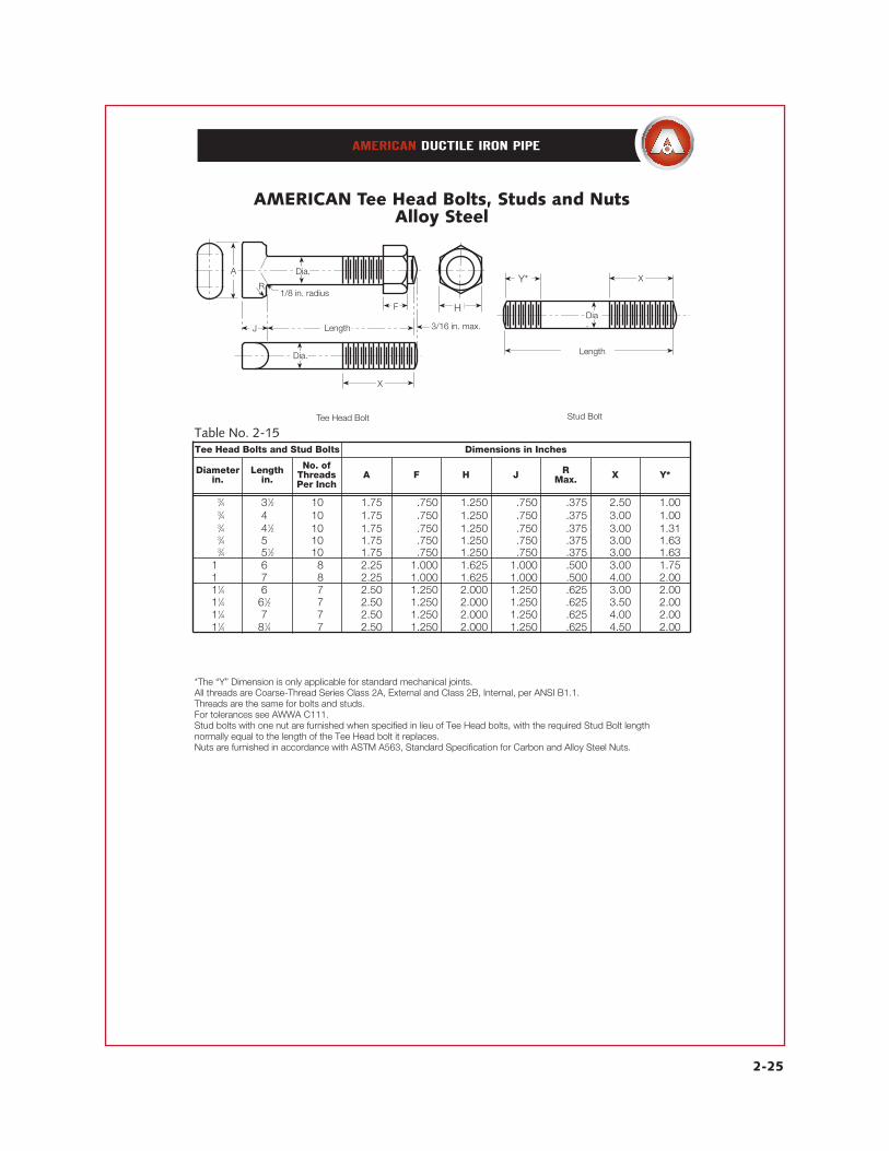
*The “Y” Dimension is only applicable for standard mechanical joints.All threads are Coarse-Thread Series Class 2A, External and Class 2B, Internal, per ANSI B1.1.Threads are the same for bolts and studs.For tolerances see AWWA C111.Stud bolts with one nut are furnished when specified in lieu of Tee Head bolts, with the required Stud Bolt length normally equal to the length of the Tee Head bolt it replaces.Nuts are furnished in accordance with ASTM A563, Standard Specification for Carbon and Alloy Steel Nuts.
AMERICAN Tee Head Bolts, Studs and NutsAlloy Steel
X
Dia.
Length
Y
Stud Bolt
MF
X
3/16 in. max.
Dia.
Dia.
LengthJ
1/8 in. radiusR
A
Tee Head Bolt
Table No. 2-15
13⁄4 31⁄2 10 1.75 .750 1.250 .750 .375 2.50 1.0013⁄4 43⁄4 10 1.75 .750 1.250 .750 .375 3.00 1.0013⁄4 41⁄2 10 1.75 .750 1.250 .750 .375 3.00 1.3113⁄4 53⁄4 10 1.75 .750 1.250 .750 .375 3.00 1.6313⁄4 51⁄2 10 1.75 .750 1.250 .750 .375 3.00 1.6313⁄4 63⁄4 18 2.25 1.000 1.625 1.000 .500 3.00 1.7513⁄4 73⁄4 18 2.25 1.000 1.625 1.000 .500 4.00 2.0011⁄4 63⁄4 17 2.50 1.250 2.000 1.250 .625 3.00 2.0011⁄4 61⁄23⁄4 17 2.50 1.250 2.000 1.250 .625 3.50 2.0011⁄4 73⁄4 17 2.50 1.250 2.000 1.250 .625 4.00 2.00
Diameterin.
Lengthin.
No. ofThreadsPer Inch
A F H J RMax. X Y*
H
Y*
11⁄4 81⁄43⁄4 17 2.50 1.250 2.000 1.250 .625 4.50 2.00
Tee Head Bolts and Stud Bolts Dimensions in Inches

AMERICAN reserves the right to modify or change designs, materials, specifications, or dimensions shown herein without prior notice.
This is an on-line edition of a section from the out-of-print 19th Edition of the AMERICAN Pipe Manual. References may be made in this section to
other sections of the AMERICAN Pipe Manual. Those other sections are also available at www.american-usa.com as an on-line reference.