Embed Size (px)
Citation preview
AMETEK JOFRA APCAdvanced Pressure Calibrator
Reference Manual

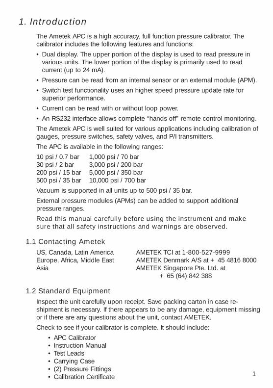
1. IntroductionThe Ametek APC is a high accuracy, full function pressure calibrator. Thecalibrator includes the following features and functions:
• Dual display. The upper portion of the display is used to read pressure invarious units. The lower portion of the display is primarily used to readcurrent (up to 24 mA).
• Pressure can be read from an internal sensor or an external module (APM).
• Switch test functionality uses an higher speed pressure update rate forsuperior performance.
• Current can be read with or without loop power.
• An RS232 interface allows complete “hands off” remote control monitoring.
The Ametek APC is well suited for various applications including calibration ofgauges, pressure switches, safety valves, and P/I transmitters.
The APC is available in the following ranges:
10 psi / 0.7 bar 1,000 psi / 70 bar30 psi / 2 bar 3,000 psi / 200 bar200 psi / 15 bar 5,000 psi / 350 bar500 psi / 35 bar 10,000 psi / 700 bar
Vacuum is supported in all units up to 500 psi / 35 bar.
External pressure modules (APMs) can be added to support additionalpressure ranges.
Read this manual carefully before using the instrument and makesure that all safety instructions and warnings are observed.
1.1 Contacting AmetekUS, Canada, Latin America AMETEK TCI at 1-800-527-9999Europe, Africa, Middle East AMETEK Denmark A/S at + 45 4816 8000Asia AMETEK Singapore Pte. Ltd. at
+ 65 (64) 842 388
1.2 Standard EquipmentInspect the unit carefully upon receipt. Save packing carton in case re-shipment is necessary. If there appears to be any damage, equipment missingor if there are any questions about the unit, contact AMETEK.
Check to see if your calibrator is complete. It should include:
• APC Calibrator• Instruction Manual• Test Leads• Carrying Case• (2) Pressure Fittings• Calibration Certificate 1
1.3 Safety information
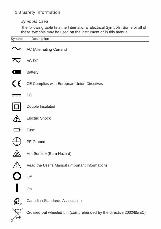
Symbols Used
The following table lists the International Electrical Symbols. Some or all ofthese symbols may be used on the instrument or in this manual.
Symbol Description
AC (Alternating Current)
AC-DC
Battery
CE Complies with European Union Directives
DC
Double Insulated
Electric Shock
Fuse
PE Ground
Hot Surface (Burn Hazard)
Read the User’s Manual (Important Information)
Off
On
Canadian Standards Association
Crossed out wheeled bin (comprehended by the directive 2002/95/EC)
2
The following definitions apply to the terms “Warning” and “Caution”.
• “Warning” identifies conditions and actions that may pose hazards to theuser.
• “Caution” identifies conditions and actions that may damage theinstrument being used.
Use the calibrator only as specified in this manual, otherwise injury anddamage to the calibrator may occur.
WarningTo avoid possible electric shock or personal injury:
• Do not apply more than the rated voltage. See specifications forsupported ranges.
• Thermostats must not be connected to any other voltage source duringa test
• Follow all equipment safety procedures.
• Never touch the probe to a voltage source when the test leads areplugged into the current terminals.
• Do not use the calibrator if it is damaged. Before you use the calibrator,inspect the case. Look for cracks or missing plastic. Pay particularattention to the insulation surrounding the connectors.
• Select the proper function and range for your measurement.
• Make sure the battery cover is closed and latched before you operate thecalibrator.
• Remove test leads from the calibrator before you open the battery door.
• Inspect the test leads for damaged insulation or exposed metal. Checktest leads continuity. Replace damaged test leads before you use thecalibrator.
• When using the probes, keep your fingers away from the probe contacts.Keep your fingers behind the finger guards on the probes.
• Connect the common test lead before you connect the live test lead.When you disconnect test leads, disconnect the live test lead first.
• Do not use the calibrator if it operates abnormally. Protection may beimpaired. When in doubt, have the calibrator serviced.
• Do not operate the calibrator around explosive gas, vapor, or dust.
• When using a pressure module, make sure the process pressure line isshut off and depressurized before you connect it or disconnect it fromthe APC or pressure module.
• Disconnect test leads before changing to another measure or sourcefunction.
3
• When servicing the calibrator, use only specified replacement parts.
• To avoid false readings, which could lead to possible electric shock orpersonal injury, replace the battery as soon as the battery indicatorappears.
• To avoid personal injury or damage to the calibrator, use only thespecified replacement parts and do not allow water into the case
CautionTo avoid possible damage to calibrator or to equipment under test:
• Disconnect the power and discharge all high-voltage capacitors beforetesting resistance or continuity.
• Use the proper jacks, function, and range for your measurement orsourcing application.
• If the message changes to "OL" the range limit is exceeded and thepressure source must immediately be removed from the APC to preventdamage to the pressure transducer inside.
• Maximum torque allowed is 15Nm/10 ftlbs. NEVER exceed the torqueallowed.
• To avoid damaging the plastic lens and case, do not use solvents orabrasive cleansers.
Clean the calibrator with a soft cloth dampened with water or water andmild soap.
4
5
2. Calibrator Interface
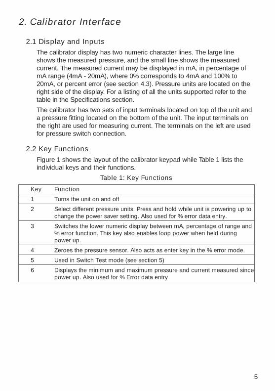
2.1 Display and InputsThe calibrator display has two numeric character lines. The large lineshows the measured pressure, and the small line shows the measuredcurrent. The measured current may be displayed in mA, in percentage ofmA range (4mA - 20mA), where 0% corresponds to 4mA and 100% to20mA, or percent error (see section 4.3). Pressure units are located on theright side of the display. For a listing of all the units supported refer to thetable in the Specifications section.
The calibrator has two sets of input terminals located on top of the unit anda pressure fitting located on the bottom of the unit. The input terminals onthe right are used for measuring current. The terminals on the left are usedfor pressure switch connection.
2.2 Key FunctionsFigure 1 shows the layout of the calibrator keypad while Table 1 lists theindividual keys and their functions.
Table 1: Key Functions
Key Function
1 Turns the unit on and off
2 Select different pressure units. Press and hold while unit is powering up tochange the power saver setting. Also used for % error data entry.
3 Switches the lower numeric display between mA, percentage of range and% error function. This key also enables loop power when held duringpower up.
4 Zeroes the pressure sensor. Also acts as enter key in the % error mode.
5 Used in Switch Test mode (see section 5)
6 Displays the minimum and maximum pressure and current measured sincepower up. Also used for % Error data entry

6
Figure 1
2.3 Power SaverThe calibrator has an adjustable power saver option that allows it to shutdown after being idle (no keys pressed) for a period of 1 to 30 minutes. Toset the shutoff time:
1. Press and hold the (UNITS) key while powering up the unit.
2. A number from 1 to 30 or OFF will appear on the bottom of the display.
3. Use the (UNITS) key to increase the number, and the (MAX/MIN) key todecrease the number.
4. To disable power saver mode decrease the number until OFF isdisplayed on the screen.
5. Press the (ZERO) key to save the settings and return to normaloperation.
7
3. Measuring Pressure and Current
WarningMake sure the process pressure line is shut off and depressurized beforeyou connect it or disconnect it from the APC or pressure module.
Caution• If the message changes to "OL" the range limit is exceeded and the
pressure source must immediately be removed from the APC to preventdamage to the pressure transducer inside.
• Maximum torque allowed is 15Nm/xx ftlbs. NEVER exceed the torqueallowed.
To measure pressure, connect the calibrator using an appropriate fitting.Choose a pressure unit for measurement with the (UNITS) key. Pressure willbe displayed on the large numeric display. Use the (ZERO) key to zero thepressure sensor when vented to atmospheric pressure
Important NOTE: To ensure accuracy of the calibrator it is critical to zerothe APC before a device is calibrated.
To measure current use the mA input terminals on the top of the calibrator.Current can be measured in mA or percentage of range. The range on thecalibrator is set to 0% at 4 mA and 100% at 20 mA. For for example if thecurrent measured is displayed as 75% then the mA value is 16 mA.
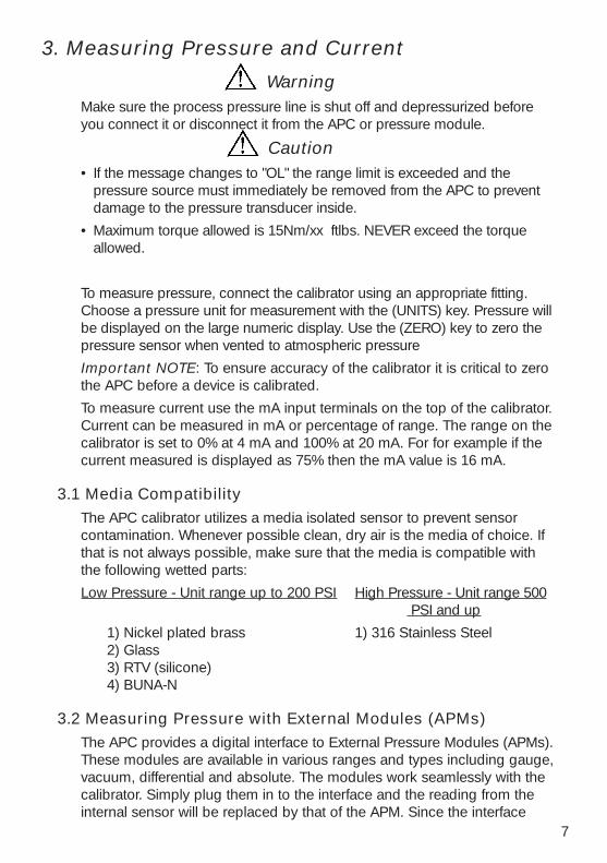
3.1 Media CompatibilityThe APC calibrator utilizes a media isolated sensor to prevent sensorcontamination. Whenever possible clean, dry air is the media of choice. Ifthat is not always possible, make sure that the media is compatible withthe following wetted parts:
Low Pressure - Unit range up to 200 PSI High Pressure - Unit range 500 PSI and up
1) Nickel plated brass 1) 316 Stainless Steel2) Glass3) RTV (silicone)4) BUNA-N
3.2 Measuring Pressure with External Modules (APMs)The APC provides a digital interface to External Pressure Modules (APMs).These modules are available in various ranges and types including gauge,vacuum, differential and absolute. The modules work seamlessly with thecalibrator. Simply plug them in to the interface and the reading from theinternal sensor will be replaced by that of the APM. Since the interface
8
between the APC and the APM is digital all the accuracy and displayresolution is derived from the APM.
3.3 Zeroing of External Modules (APMs)The zeroing of the APM is stored separately from that of the internal sensor.Use the (ZERO) key to zero the APM. For zeroing of absolute APMs, usethe (▲), (▼) and (ENTER) keys to enter the barometric reference pressure.The APC stores barometric reference pressure for one absolute module ata time.
3.4 Minimum and Maximum MeasurementsThe calibrator automatically records the maximum and minimum values forpressure that were read by the calibrator since it has been turned on orreset. The current or mA reading is also stored for the correspondingpressure value. To recall the recorded values from memory press the(MAX/MIN) key. To clear the memory press and hold the (MAX/MIN) keyuntil “CLR” is displayed.
4. Calibrating Transmitters
Warning• Do not apply more than the rated voltage. See specifications for
supported ranges.
• Thermostats must not be connected to any other voltage source during atest
Caution• Disconnect the power and discharge all high-voltage capacitors before
testing resistance or continuity.
4.1 Using the mA Input FunctionThe mA input function allows the user to read back the 4 to 20 mA outputfrom the device being calibrated. This can be done in one of two ways:
1. Passively – Where the device under test directly generates a 4 to 20 mAand can be read by the APC
2. Actively – Where the APC supplies 24 VDC loop power to the deviceunder test to power the device while reading the resulting 4to 20 mA signal.
When the APC is first powered up it always defaults to the passive mAinput mode. To activate loop power do the following steps:
1. Before turning on the APC press and hold down the (% mA) key.
9
2. Press the Power key while continuing to hold down the (% mA) key.
3. Allow the unit to go through the initial power-up sequence (about 5seconds) then release the (% mA) key.
4. Note that the LCD will display LOOP PWR. Loop power will remain onuntil the APC is turned off. Remember loop power is only activatedwhen this sequence is followed. Unless this sequence is performedduring power up the APC will always default to the passive input mode.
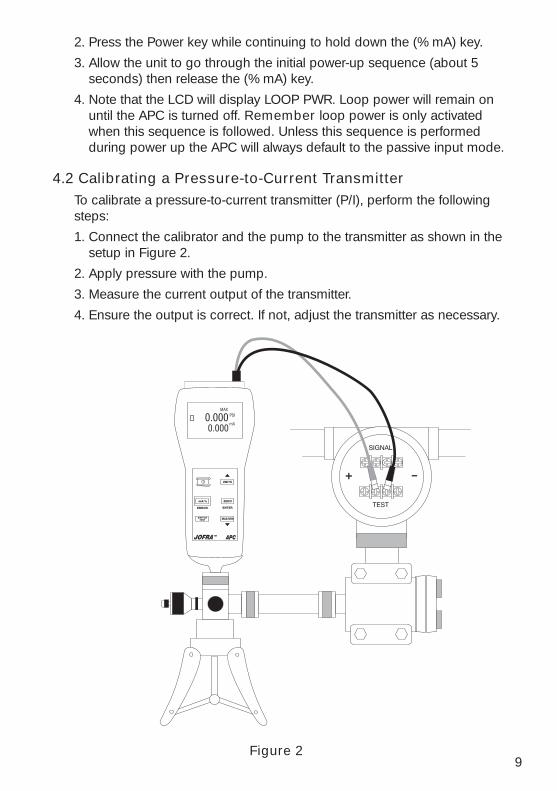
4.2 Calibrating a Pressure-to-Current TransmitterTo calibrate a pressure-to-current transmitter (P/I), perform the followingsteps:
1. Connect the calibrator and the pump to the transmitter as shown in thesetup in Figure 2.
2. Apply pressure with the pump.
3. Measure the current output of the transmitter.
4. Ensure the output is correct. If not, adjust the transmitter as necessary.
Figure 2
10
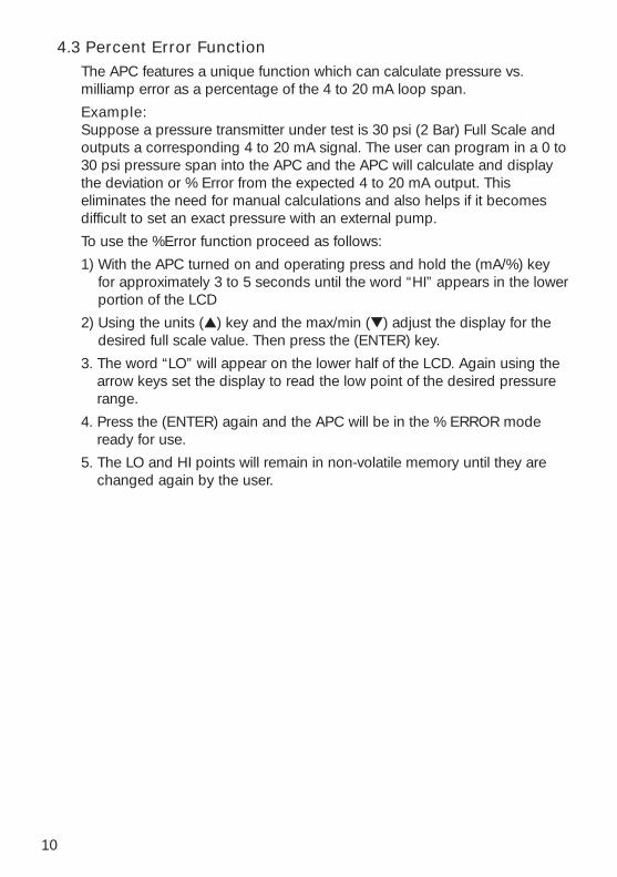
4.3 Percent Error FunctionThe APC features a unique function which can calculate pressure vs.milliamp error as a percentage of the 4 to 20 mA loop span.
Example:Suppose a pressure transmitter under test is 30 psi (2 Bar) Full Scale andoutputs a corresponding 4 to 20 mA signal. The user can program in a 0 to30 psi pressure span into the APC and the APC will calculate and displaythe deviation or % Error from the expected 4 to 20 mA output. Thiseliminates the need for manual calculations and also helps if it becomesdifficult to set an exact pressure with an external pump.
To use the %Error function proceed as follows:
1) With the APC turned on and operating press and hold the (mA/%) keyfor approximately 3 to 5 seconds until the word “HI” appears in the lowerportion of the LCD
2) Using the units (▲) key and the max/min (▼) adjust the display for thedesired full scale value. Then press the (ENTER) key.
3. The word “LO” will appear on the lower half of the LCD. Again using thearrow keys set the display to read the low point of the desired pressurerange.
4. Press the (ENTER) again and the APC will be in the % ERROR modeready for use.
5. The LO and HI points will remain in non-volatile memory until they arechanged again by the user.
11
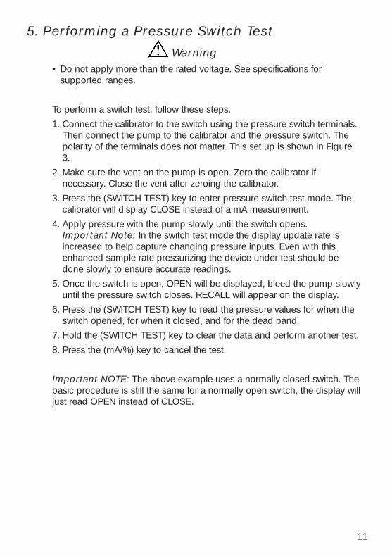
5. Performing a Pressure Switch Test
Warning• Do not apply more than the rated voltage. See specifications for
supported ranges.
To perform a switch test, follow these steps:
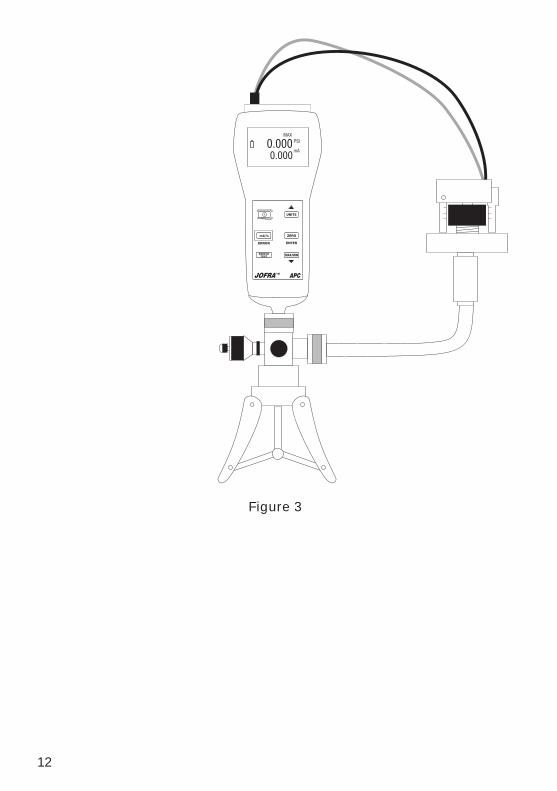
1. Connect the calibrator to the switch using the pressure switch terminals.Then connect the pump to the calibrator and the pressure switch. Thepolarity of the terminals does not matter. This set up is shown in Figure3.
2. Make sure the vent on the pump is open. Zero the calibrator ifnecessary. Close the vent after zeroing the calibrator.
3. Press the (SWITCH TEST) key to enter pressure switch test mode. Thecalibrator will display CLOSE instead of a mA measurement.
4. Apply pressure with the pump slowly until the switch opens. Important Note: In the switch test mode the display update rate isincreased to help capture changing pressure inputs. Even with thisenhanced sample rate pressurizing the device under test should bedone slowly to ensure accurate readings.
5. Once the switch is open, OPEN will be displayed, bleed the pump slowlyuntil the pressure switch closes. RECALL will appear on the display.
6. Press the (SWITCH TEST) key to read the pressure values for when theswitch opened, for when it closed, and for the dead band.
7. Hold the (SWITCH TEST) key to clear the data and perform another test.
8. Press the (mA/%) key to cancel the test.
Important NOTE: The above example uses a normally closed switch. Thebasic procedure is still the same for a normally open switch, the display willjust read OPEN instead of CLOSE.
12
Figure 3
13
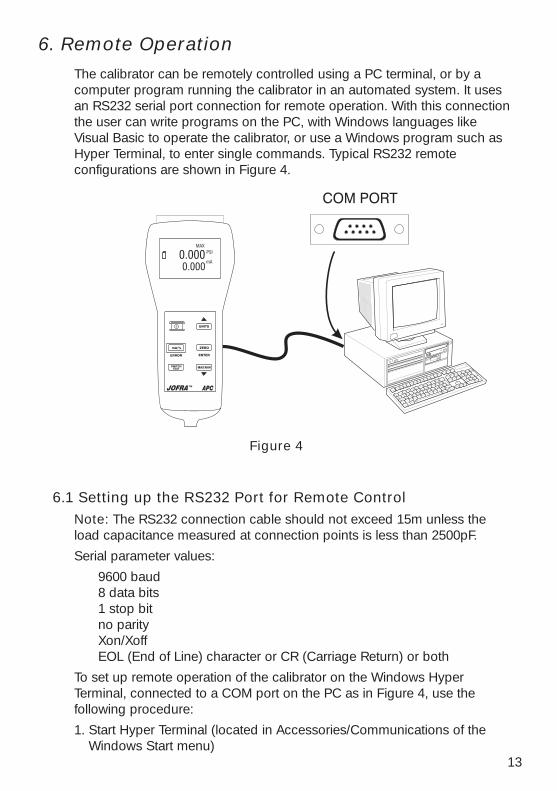
6. Remote OperationThe calibrator can be remotely controlled using a PC terminal, or by acomputer program running the calibrator in an automated system. It usesan RS232 serial port connection for remote operation. With this connectionthe user can write programs on the PC, with Windows languages likeVisual Basic to operate the calibrator, or use a Windows program such asHyper Terminal, to enter single commands. Typical RS232 remoteconfigurations are shown in Figure 4.
Figure 4
6.1 Setting up the RS232 Port for Remote ControlNote: The RS232 connection cable should not exceed 15m unless theload capacitance measured at connection points is less than 2500pF.
Serial parameter values:
9600 baud8 data bits1 stop bitno parityXon/XoffEOL (End of Line) character or CR (Carriage Return) or both
To set up remote operation of the calibrator on the Windows HyperTerminal, connected to a COM port on the PC as in Figure 4, use thefollowing procedure:
1. Start Hyper Terminal (located in Accessories/Communications of theWindows Start menu)
14
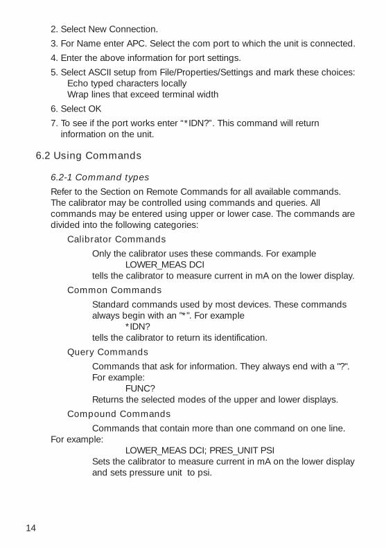
2. Select New Connection.
3. For Name enter APC. Select the com port to which the unit is connected.
4. Enter the above information for port settings.
5. Select ASCII setup from File/Properties/Settings and mark these choices:Echo typed characters locallyWrap lines that exceed terminal width
6. Select OK
7. To see if the port works enter “*IDN?”. This command will returninformation on the unit.
6.2 Using Commands
6.2-1 Command types
Refer to the Section on Remote Commands for all available commands.The calibrator may be controlled using commands and queries. Allcommands may be entered using upper or lower case. The commands aredivided into the following categories:
Calibrator Commands
Only the calibrator uses these commands. For example LOWER_MEAS DCI
tells the calibrator to measure current in mA on the lower display.
Common Commands
Standard commands used by most devices. These commandsalways begin with an "*". For example
*IDN?tells the calibrator to return its identification.
Query Commands
Commands that ask for information. They always end with a "?".For example:
FUNC?Returns the selected modes of the upper and lower displays.
Compound Commands
Commands that contain more than one command on one line.For example:
LOWER_MEAS DCI; PRES_UNIT PSISets the calibrator to measure current in mA on the lower displayand sets pressure unit to psi.
15
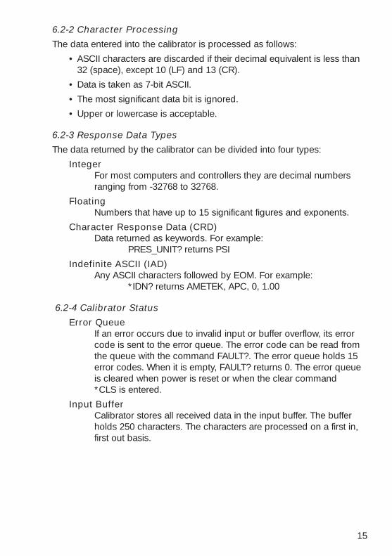
6.2-2 Character Processing
The data entered into the calibrator is processed as follows:
• ASCII characters are discarded if their decimal equivalent is less than32 (space), except 10 (LF) and 13 (CR).
• Data is taken as 7-bit ASCII.
• The most significant data bit is ignored.
• Upper or lowercase is acceptable.
6.2-3 Response Data Types
The data returned by the calibrator can be divided into four types:
IntegerFor most computers and controllers they are decimal numbersranging from -32768 to 32768.
FloatingNumbers that have up to 15 significant figures and exponents.
Character Response Data (CRD)Data returned as keywords. For example:
PRES_UNIT? returns PSI
Indefinite ASCII (IAD)Any ASCII characters followed by EOM. For example:
*IDN? returns AMETEK, APC, 0, 1.00
6.2-4 Calibrator Status
Error QueueIf an error occurs due to invalid input or buffer overflow, its errorcode is sent to the error queue. The error code can be read fromthe queue with the command FAULT?. The error queue holds 15error codes. When it is empty, FAULT? returns 0. The error queueis cleared when power is reset or when the clear command*CLS is entered.
Input BufferCalibrator stores all received data in the input buffer. The bufferholds 250 characters. The characters are processed on a first in,first out basis.
16
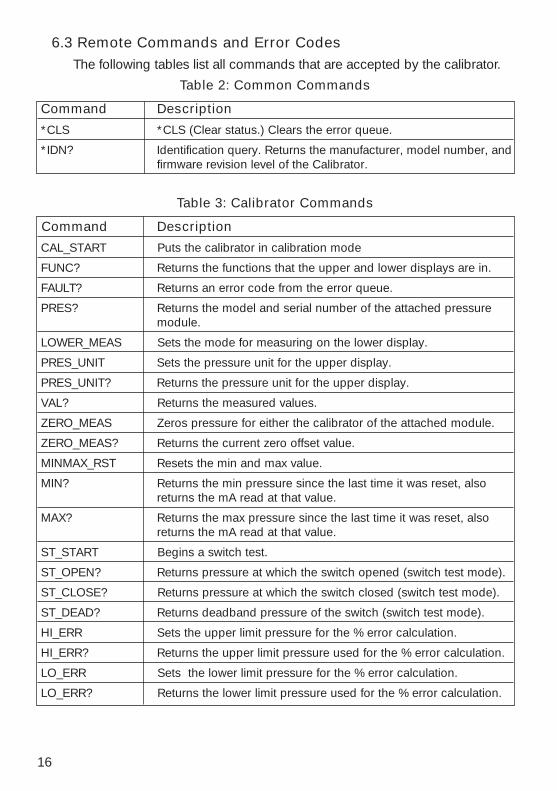
6.3 Remote Commands and Error CodesThe following tables list all commands that are accepted by the calibrator.
Table 2: Common Commands
Command Description
*CLS *CLS (Clear status.) Clears the error queue.
*IDN? Identification query. Returns the manufacturer, model number, andfirmware revision level of the Calibrator.
Table 3: Calibrator Commands
Command Description
CAL_START Puts the calibrator in calibration mode
FUNC? Returns the functions that the upper and lower displays are in.
FAULT? Returns an error code from the error queue.
PRES? Returns the model and serial number of the attached pressuremodule.
LOWER_MEAS Sets the mode for measuring on the lower display.
PRES_UNIT Sets the pressure unit for the upper display.
PRES_UNIT? Returns the pressure unit for the upper display.
VAL? Returns the measured values.
ZERO_MEAS Zeros pressure for either the calibrator of the attached module.
ZERO_MEAS? Returns the current zero offset value.
MINMAX_RST Resets the min and max value.
MIN? Returns the min pressure since the last time it was reset, alsoreturns the mA read at that value.
MAX? Returns the max pressure since the last time it was reset, alsoreturns the mA read at that value.
ST_START Begins a switch test.
ST_OPEN? Returns pressure at which the switch opened (switch test mode).
ST_CLOSE? Returns pressure at which the switch closed (switch test mode).
ST_DEAD? Returns deadband pressure of the switch (switch test mode).
HI_ERR Sets the upper limit pressure for the % error calculation.
HI_ERR? Returns the upper limit pressure used for the % error calculation.
LO_ERR Sets the lower limit pressure for the % error calculation.
LO_ERR? Returns the lower limit pressure used for the % error calculation.
17
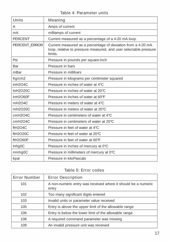
Table 4: Parameter units
Units Meaning
A Amps of current
mA milliamps of current
PERCENT Current measured as a percentage of a 4-20 mA loop.
PERCENT_ERROR Current measured as a percentage of deviation from a 4-20 mAloop, relative to pressure measured, and user selectable pressurelimits.
Psi Pressure in pounds per square-inch
Bar Pressure in bars
mBar Pressure in millibars
Kg/cm2 Pressure in kilograms per centimeter squared
InH2O4C Pressure in inches of water at 4°C
InH2O20C Pressure in inches of water at 20°C
InH2O60F Pressure in inches of water at 60°F
mH2O4C Pressure in meters of water at 4°C
mH2O20C Pressure in meters of water at 20°C
cmH2O4C Pressure in centimeters of water at 4°C
cmH2O4C Pressure in centimeters of water at 20°C
ftH2O4C Pressure in feet of water at 4°C
ftH2O20C Pressure in feet of water at 20°C
ftH2O60F Pressure in feet of water at 60°F
Inhg0C Pressure in inches of mercury at 0°C
mmhg0C Pressure in millimeters of mercury at 0°C
kpal Pressure in kiloPascals
Table 5: Error codes
Error Number Error Description
101 A non-numeric entry was received where it should be a numericentry
102 Too many significant digits entered
103 Invalid units or parameter value received
105 Entry is above the upper limit of the allowable range
106 Entry is below the lower limit of the allowable range
108 A required command parameter was missing
109 An invalid pressure unit was received
18
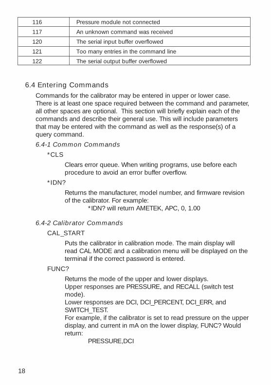
116 Pressure module not connected
117 An unknown command was received
120 The serial input buffer overflowed
121 Too many entries in the command line
122 The serial output buffer overflowed
6.4 Entering CommandsCommands for the calibrator may be entered in upper or lower case.There is at least one space required between the command and parameter,all other spaces are optional. This section will briefly explain each of thecommands and describe their general use. This will include parametersthat may be entered with the command as well as the response(s) of aquery command.
6.4-1 Common Commands
*CLS
Clears error queue. When writing programs, use before eachprocedure to avoid an error buffer overflow.
*IDN?
Returns the manufacturer, model number, and firmware revisionof the calibrator. For example:
*IDN? will return AMETEK, APC, 0, 1.00
6.4-2 Calibrator Commands
CAL_START
Puts the calibrator in calibration mode. The main display willread CAL MODE and a calibration menu will be displayed on theterminal if the correct password is entered.
FUNC?
Returns the mode of the upper and lower displays. Upper responses are PRESSURE, and RECALL (switch testmode).Lower responses are DCI, DCI_PERCENT, DCI_ERR, andSWITCH_TEST.For example, if the calibrator is set to read pressure on the upperdisplay, and current in mA on the lower display, FUNC? Wouldreturn:
PRESSURE,DCI
19
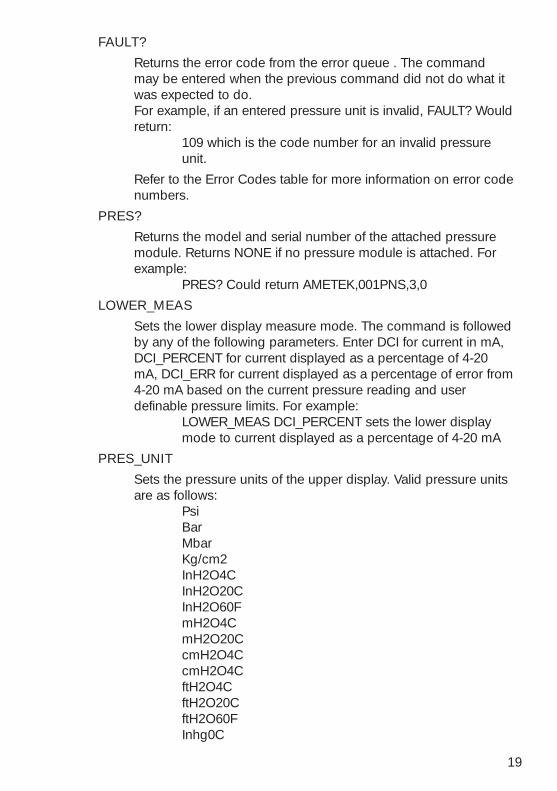
FAULT?
Returns the error code from the error queue . The commandmay be entered when the previous command did not do what itwas expected to do.For example, if an entered pressure unit is invalid, FAULT? Wouldreturn:
109 which is the code number for an invalid pressureunit.
Refer to the Error Codes table for more information on error codenumbers.
PRES?
Returns the model and serial number of the attached pressuremodule. Returns NONE if no pressure module is attached. Forexample:
PRES? Could return AMETEK,001PNS,3,0
LOWER_MEAS
Sets the lower display measure mode. The command is followedby any of the following parameters. Enter DCI for current in mA,DCI_PERCENT for current displayed as a percentage of 4-20mA, DCI_ERR for current displayed as a percentage of error from4-20 mA based on the current pressure reading and userdefinable pressure limits. For example:
LOWER_MEAS DCI_PERCENT sets the lower displaymode to current displayed as a percentage of 4-20 mA
PRES_UNIT
Sets the pressure units of the upper display. Valid pressure unitsare as follows:
PsiBarMbarKg/cm2InH2O4CInH2O20CInH2O60FmH2O4CmH2O20CcmH2O4CcmH2O4CftH2O4CftH2O20CftH2O60FInhg0C
20
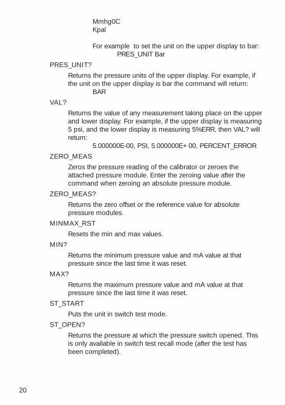
Mmhg0CKpal
For example to set the unit on the upper display to bar:PRES_UNIT Bar
PRES_UNIT?
Returns the pressure units of the upper display. For example, ifthe unit on the upper display is bar the command will return:
BAR
VAL?
Returns the value of any measurement taking place on the upperand lower display. For example, if the upper display is measuring5 psi, and the lower display is measuring 5%ERR, then VAL? willreturn:
5.000000E-00, PSI, 5.000000E+00, PERCENT_ERROR
ZERO_MEAS
Zeros the pressure reading of the calibrator or zeroes theattached pressure module. Enter the zeroing value after thecommand when zeroing an absolute pressure module.
ZERO_MEAS?
Returns the zero offset or the reference value for absolutepressure modules.
MINMAX_RST
Resets the min and max values.
MIN?
Returns the minimum pressure value and mA value at thatpressure since the last time it was reset.
MAX?
Returns the maximum pressure value and mA value at thatpressure since the last time it was reset.
ST_START
Puts the unit in switch test mode.
ST_OPEN?
Returns the pressure at which the pressure switch opened. Thisis only available in switch test recall mode (after the test hasbeen completed).
21
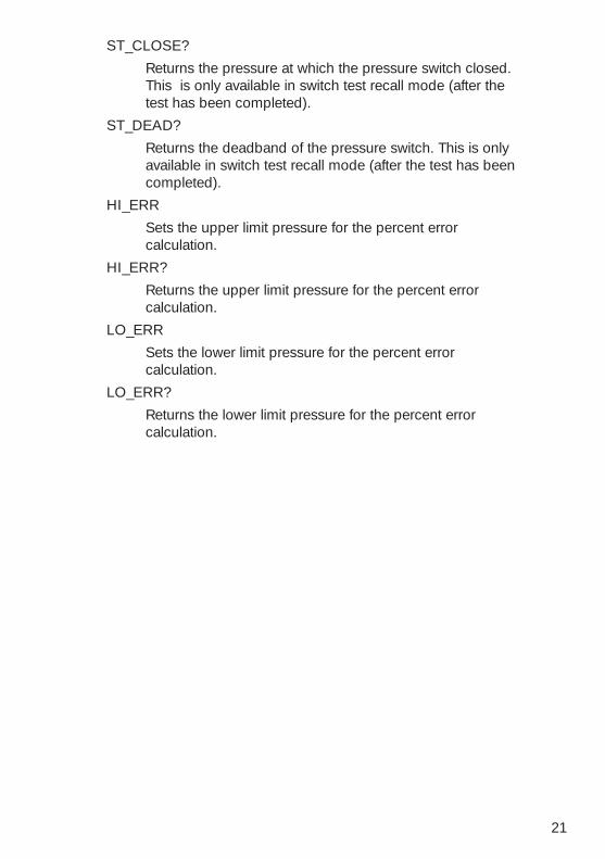
ST_CLOSE?
Returns the pressure at which the pressure switch closed.This is only available in switch test recall mode (after thetest has been completed).
ST_DEAD?
Returns the deadband of the pressure switch. This is onlyavailable in switch test recall mode (after the test has beencompleted).
HI_ERR
Sets the upper limit pressure for the percent errorcalculation.
HI_ERR?
Returns the upper limit pressure for the percent errorcalculation.
LO_ERR
Sets the lower limit pressure for the percent errorcalculation.
LO_ERR?
Returns the lower limit pressure for the percent errorcalculation.
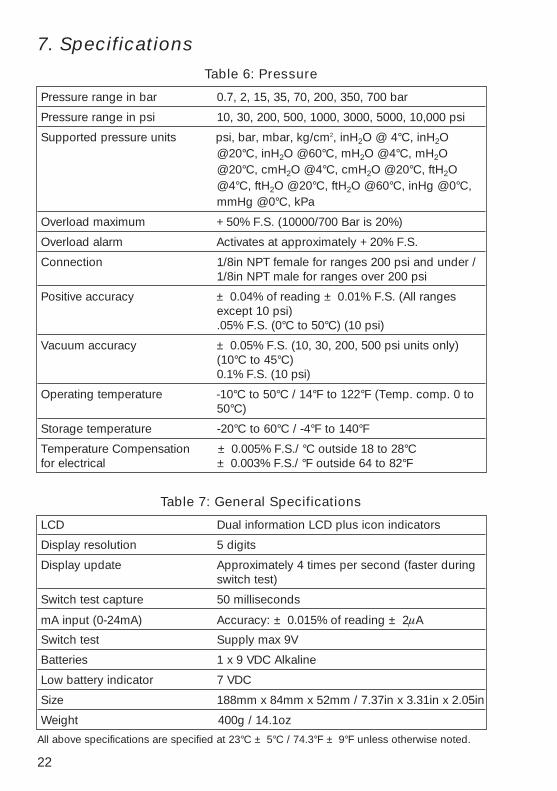
7. SpecificationsTable 6: Pressure
Pressure range in bar 0.7, 2, 15, 35, 70, 200, 350, 700 bar
Pressure range in psi 10, 30, 200, 500, 1000, 3000, 5000, 10,000 psi
Supported pressure units psi, bar, mbar, kg/cm2, inH2O @ 4°C, inH2O@20°C, inH2O @60°C, mH2O @4°C, mH2O@20°C, cmH2O @4°C, cmH2O @20°C, ftH2O@4°C, ftH2O @20°C, ftH2O @60°C, inHg @0°C,mmHg @0°C, kPa
Overload maximum +50% F.S. (10000/700 Bar is 20%)
Overload alarm Activates at approximately +20% F.S.
Connection 1/8in NPT female for ranges 200 psi and under /1/8in NPT male for ranges over 200 psi
Positive accuracy ± 0.04% of reading ± 0.01% F.S. (All rangesexcept 10 psi).05% F.S. (0°C to 50°C) (10 psi)
Vacuum accuracy ± 0.05% F.S. (10, 30, 200, 500 psi units only)(10°C to 45°C)0.1% F.S. (10 psi)
Operating temperature -10°C to 50°C / 14°F to 122°F (Temp. comp. 0 to50°C)
Storage temperature -20°C to 60°C / -4°F to 140°F
Temperature Compensation ± 0.005% F.S./ °C outside 18 to 28°Cfor electrical ± 0.003% F.S./ °F outside 64 to 82°F
Table 7: General Specifications
LCD Dual information LCD plus icon indicators
Display resolution 5 digits
Display update Approximately 4 times per second (faster duringswitch test)
Switch test capture 50 milliseconds
mA input (0-24mA) Accuracy: ± 0.015% of reading ± 2µA
Switch test Supply max 9V
Batteries 1 x 9 VDC Alkaline
Low battery indicator 7 VDC
Size 188mm x 84mm x 52mm / 7.37in x 3.31in x 2.05in
Weight 400g / 14.1oz
All above specifications are specified at 23°C ± 5°C / 74.3°F ± 9°F unless otherwise noted.
22
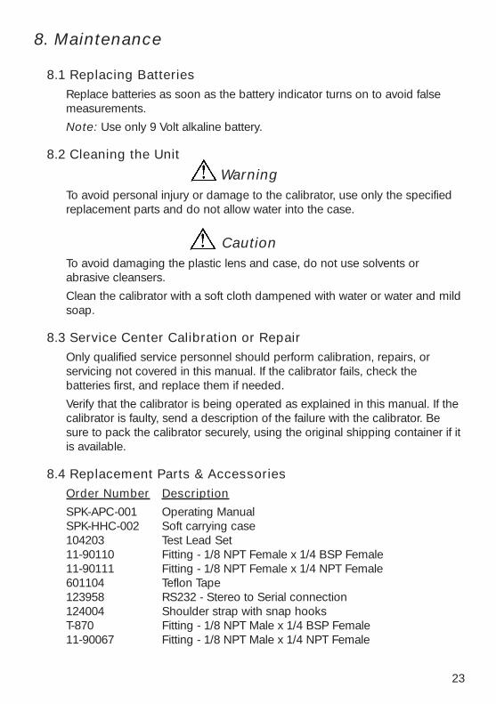
8. Maintenance
8.1 Replacing BatteriesReplace batteries as soon as the battery indicator turns on to avoid falsemeasurements.
Note: Use only 9 Volt alkaline battery.
8.2 Cleaning the Unit
WarningTo avoid personal injury or damage to the calibrator, use only the specifiedreplacement parts and do not allow water into the case.
CautionTo avoid damaging the plastic lens and case, do not use solvents orabrasive cleansers.
Clean the calibrator with a soft cloth dampened with water or water and mildsoap.
8.3 Service Center Calibration or Repair Only qualified service personnel should perform calibration, repairs, orservicing not covered in this manual. If the calibrator fails, check thebatteries first, and replace them if needed.
Verify that the calibrator is being operated as explained in this manual. If thecalibrator is faulty, send a description of the failure with the calibrator. Besure to pack the calibrator securely, using the original shipping container if itis available.
8.4 Replacement Parts & AccessoriesOrder Number Description
SPK-APC-001 Operating ManualSPK-HHC-002 Soft carrying case104203 Test Lead Set11-90110 Fitting - 1/8 NPT Female x 1/4 BSP Female11-90111 Fitting - 1/8 NPT Female x 1/4 NPT Female601104 Teflon Tape123958 RS232 - Stereo to Serial connection124004 Shoulder strap with snap hooksT-870 Fitting - 1/8 NPT Male x 1/4 BSP Female 11-90067 Fitting - 1/8 NPT Male x 1/4 NPT Female
23

24


SPK-APC-001 0219133 Rev D 1/05
AMETEKTest & Calibration Instruments Division
8600 Somerset DriveLargo, FL 33773 USA
TEL 727-536-7831TOLL-FREE 800-527-9999
FAX 727-539-6882E-mail: [email protected]
AMETEK Denmark A/S Gydevang 32-34Post Office Box 30DK-3450 Allerod
DenmarkTel +45 4816 8000Fax +45 4816 8080
E-mail [email protected]
AMETEK Precision Instruments Europe GmbHPostfach 2165
D-40644, MeerbuschGermany
Tel +49 2159 9136 0Fax +49 2159 9136 39E-mail [email protected]
AMETEK Singapore Pte. Ltd.10 Ang Mo Kio Street 65
#05-12 TECHPOINTSingapore 569059Tel +65 6484 2388Fax +65 6481 6588
E-mail [email protected]