Embed Size (px)
Citation preview

Technical GuideTechnical GuideTechnical GuideTechnical GuideTechnical Guide
Feature Overview and Configuration Guide
Allied Telesis Management Framework™ (AMF)
Introduction to AMFThe Allied Telesis Management Framework (AMF) is a suite of features that combine to
simplify network management across all supported network equipment from the core to
the edge.
AMF provides simplified device recovery and firmware upgrade management. The primary
function of AMF is to reduce the management and maintenance overhead on a network,
while improving its responsiveness in handling equipment failures.
AMF enables an entire network to be managed as a single virtual device from any node,
excepting guest nodes, (AMF guests) within the network. Configuration changes can
be simultaneously made on multiple devices, and new devices can easily be
assimilated into the network.
AMF can easily be overlaid on top of an existing network without changing its physical
topology. AMF will determine the optimal logical topology for its own control plane.
AMF’s features enable network engineers to lower network operating costs by reducing
the complexity of network management and automating many routine tasks.
This guide provides a conceptual introduction to AMF, together with its benefits, and
presents configuration guidelines that explain the practical application of AMF in real
networks.
x alliedtelesis.comC613-22047-00 REV G

Allied Telesis Management Framework™ (AMF)
Products and software version that apply to this guide
This guide applies to AlliedWare Plus™ products running version 5.4.5-0.x and later.
AMF master and controller nodes require a feature license. For information about which
products can act as AMF master or controller nodes and the available licenses, see the
AlliedWare Plus Datasheet.
The following features are supported since the following software versions:
AMF Guestnode - 5.4.6-0.x
AMF Agent for integrating x600 Series Switches - 5.4.6-1.x
AMF subscription licenses - 5.4.6-1.x
Table of ContentsIntroduction to AMF ........................................................................................................... 1
Products and software version that apply to this guide .............................................. 2
Key Benefits of AMF .......................................................................................................... 5
Unified command-line ................................................................................................. 5
Configuration backup and recovery ............................................................................ 5
Auto upgrade ............................................................................................................... 5
Node provisioning........................................................................................................ 6
Allied Telesis Management Framework (AMF) Subscription Licenses............................... 6
Managing AMF licenses .............................................................................................. 6
AMF starter license...................................................................................................... 9
Overview of an AMF Network .......................................................................................... 10
AMF Terminology ............................................................................................................. 11
AMF network ............................................................................................................. 11
AMF area ................................................................................................................... 12
AMF nodes ................................................................................................................ 12
Node interconnection ................................................................................................ 13
AMF domains............................................................................................................. 14
Virtual-links ................................................................................................................ 15
Area links ................................................................................................................... 15
AMF Network Operational Concepts ............................................................................... 16
Retention and use of the ‘manager’ username ......................................................... 16
Working-set................................................................................................................ 16
AMF restricted-login .................................................................................................. 17
Loop-free data plane ................................................................................................. 17
VCStacks ................................................................................................................... 17
Page 2 | Products and software version that apply to this guide

Allied Telesis Management Framework™ (AMF)
AMF and removable media ........................................................................................17
AMF interaction with QoS and ACLs..........................................................................18
Sharing AMF links with other network operations......................................................18
NTP and AMF .............................................................................................................19
Node licensing............................................................................................................20
AMF guestnode ..........................................................................................................20
AMF guest configuration ............................................................................................23
AMF guestnode show commands..............................................................................26
Renaming your AMF network .....................................................................................29
AMF support for x600 Series switches ......................................................................29
AMF Configuration ............................................................................................................31
Example - Configuring a simple stand-alone area .....................................................31
AMF tunneling (virtual-links) .......................................................................................35
Prioritizing the tunnel traffic to the CPU of the receiving endpoint ............................40
The Concept of AMF Areas...............................................................................................41
Configuring an AMF controller....................................................................................41
Connections from AMF controllers to the other areas ...............................................42
Example - Configuring a multi-area network..............................................................44
Configuring Multiple Nodes at the Same Time: the Unified CLI .......................................47
Working-set groups ....................................................................................................48
Executing commands on working-sets ......................................................................51
Interactive commands ................................................................................................53
AMF Backups....................................................................................................................54
Backups by master nodes..........................................................................................54
Backups by controller nodes......................................................................................54
Backups by member nodes .......................................................................................54
Controlling the backup behaviour of controller and master nodes ............................58
Scheduling backups...................................................................................................58
Backup destinations...................................................................................................59
Performing a manual backup .....................................................................................61
Backups on chassis or VCStacks running as AMF controllers or masters ................62
Forcing all master nodes in an area to perform a backup..........................................63
Backing up to remote servers ....................................................................................65
Multiple backup destinations .....................................................................................71
Node Recovery .................................................................................................................73
Recommended procedure when replacing a device using automatic node recovery75
Points to note about automatic node recovery ..........................................................76
Restoring a node to a “clean” state ...........................................................................77
Products and software version that apply to this guide | Page 3

Allied Telesis Management Framework™ (AMF)
Manual node recovery ............................................................................................... 78
Node recovery on VCStacks...................................................................................... 79
Recovery of switches that require release licenses................................................... 80
AMF Safe configuration ............................................................................................. 80
How to recover a TQ AP Guest ................................................................................. 83
Firmware Auto Upgrade ................................................................................................... 90
Advantages of reboot-rolling upgrade....................................................................... 90
Disadvantages of reboot-rolling upgrade .................................................................. 91
Advantages of distribute firmware upgrade .............................................................. 91
Support for AMF Network Upgrades ............................................................................... 91
AMF upgrade exceptions .......................................................................................... 91
Summary of the AMF upgrade process..................................................................... 92
Detailed explanation of the AMF upgrade process ................................................... 92
Example 1 - Performing a reboot-rolling upgrade ..................................................... 95
Example 2 - AMF distribute firmware upgrade.......................................................... 97
Node Provisioning ............................................................................................................ 99
When to use node provisioning ................................................................................. 99
Creating a new provisioned node ............................................................................ 100
Configuring adjacent nodes..................................................................................... 101
Connecting a provisioned node to an AMF network ............................................... 104
Special Considerations when Using LACP Aggregations as AMF Links ....................... 105
LACP global passive mode ..................................................................................... 105
Dynamically learned LACP channel-groups ............................................................ 106
Mixed LACP configuration (manual and dynamic) .................................................. 106
Page 4 | Products and software version that apply to this guide

Allied Telesis Management Framework™ (AMF)
Key Benefits of AMFThe key benefits of AMF include its unified Command Line Interface (CLI), simple
configuration backup and recovery process, smart provisioning of new network nodes,
and time-saving rolling firmware upgrade.
Unified command-line
The conventional means of configuring and controlling AlliedWare Plus™ devices is to use
their text-based Command Line Interface (CLI). In existing networks, this CLI is available
via a serial console port and also via remote login sessions such as SSH.
AMF extends this capability from managing either a single device, or a VCStack™ of
devices, through to managing a whole network all from a single (unified) CLI session.
Using the unified CLI, a network administrator can nominate either all nodes, or a subset
of nodes, within the AMF network to comprise an entity known as a working-set.
Commands can then be executed concurrently across all network nodes within this
working-set as if they were a single unit. Any existing configuration or diagnostic actions
can thus be applied to multiple devices using a single command sequence. This reduces
maintenance costs and configuration complexity, while still retaining complete flexibility in
network design and control.
Configuration backup and recovery
AMF master nodes automatically backup the complete configuration information for all
their member nodes, including boot configuration, firmware, licenses, and user scripts.
If an AMF member node should fail, the AMF process will automatically recognize and
reconfigure an unconfigured replacement (standby unit), completely recreating the stored
configuration of the failed unit into the replacement unit. The new unit will then reboot and
resume service, without any need for user intervention beyond physical hardware
replacement and cable connection. In this way AMF provides a complete zero-touch
recovery solution. For more information, see "AMF Backups" on page 54. Similarly, AMF
controller nodes can backup the master nodes of the AMF areas under their control, to
provide automatic recovery of failed masters.
Auto upgrade
Installing firmware upgrades on a production network is typically an infrequent but
sensitive and labor-intensive process. AMF is able to roll out upgrades to a user-selected
subset of nodes. All that needs to be entered is the target group of nodes, and the
location where the new firmware is stored; AMF will then take care of the rest. Nodes are
upgraded in a serial fashion, with each node being tested before continuing on to upgrade
the next node.
If an upgrade fails on a particular node, the upgrade process is automatically terminated
and that node will revert to its previous firmware version. In this way firmware updates are
almost completely hands-free, whilst also providing confidence that a bad update will not
result in loss of service. For more information, see "Firmware Auto Upgrade" on page 90.
Unified command-line | Page 5

Allied Telesis Management Framework™ (AMF)
Node provisioning
It is generally undesirable to have unconfigured devices connected to the network. Node
provisioning enables you to preconfigure a port ready to accept and automatically
configure a “clean” (as new) device for connection at a later date. This is achieved by
storing the future node's configuration in the master node's backup files ready to be
loaded to the new device when connected.
Allied Telesis Management Framework (AMF) Subscription LicensesAllied Telesis Management Framework (AMF) greatly reduces the time and cost of
managing network infrastructure.
Version 5.4.6-1.x adds support for AMF subscription licenses. To see the available
licenses, check your device’s datasheet, which is available at alliedtelesis.com.
Managing AMF licenses
To subscribe to AMF and manage your licenses, use the following steps:
Subscription licenses are tied to the serial number of the device.
Use the show system serialnumber command to display the serial number:
To purchase a subscription license, contact your authorized Allied Telesis representative.
You will need to supply the device serial number.
Subscription licenses are contained in a Capability Response File (CRF). You can
download the CRF from the Allied Telesis Download Center by logging into your account.
Once you have reached the Download Center Homepage, you can locate your device
type by clicking Search Devices from the Devices menu on the left. You can select your
specific device by clicking the serial number from the Serial Number list.
Step 1. Obtain the serial number for your AMF master and/or controller devices
awplus# show system serialnumberA05050G144700002
Step 2. Obtain the subscription license
Step 3. Download the subscription license
Page 6 | Node provisioning

Allied Telesis Management Framework™ (AMF)
From the View Device page, you can download a CRF by clicking the Download
Capability Response link. CRFs are saved as .bin files.
After you have downloaded your CRF, you can transfer it onto the device’s Flash storage
by any preferred method. For example, you can use the copy command to copy the CRF
file from a USB device to your Flash storage:
awplus#copy usb flash
Output 1: Example from the copy usb flash command
Display the filename of the CRF in Flash storage, by using the following command:
awplus#dir *.bin
Then activate it by using the following command:
awplus#license update <CRF-filename>
This command copies license entitlements from the CRF into the device's internal
encrypted license library. You can then safely delete the CRF from the device. For this
command to successfully activate the license, the CRF must be valid and be tied to the
serial number of the device.
You can verify the license by using the following command:
awplus#show license external
This displays the license name, the serial number of the device, and the license’s valid
dates.
Updating subscription licenses
If a subscription license expires, the device immediately reverts to the 3-node AMF Starter
license. Warning messages will be printed in the device log 28 days, 21 days, 14 days, 7
days, and 1 day prior to a license expiring. The Allied Telesis Download Center will also
send you an email reminder prior to your license expiring.
To renew your license, contact your Allied Telesis representative. You can use the
command show license external to confirm the serial number of the device. After
renewing the license, follow steps 3-6 above to download and activate it.
Step 4. Load the subscription license onto the device
awplus#copy usb flashEnter source path with file name[]:A05050G144700002.binCopying...Successful operation
Step 5. Activate the subscription license
Step 6. Verify your CRF activation
Managing AMF licenses | Page 7

Allied Telesis Management Framework™ (AMF)
Subscription licenses on VCStacks
If you are licensing a VCStack, you only need to purchase a license for one member of the
stack. This does not need to be the VCStack master.
To load the license onto the stack, follow the steps above on the stack master. The
software checks that the CRF is valid for one of the stack members and applies the
license entitlement to all members of the stack. The command show license external
stored shows which stack member is the source of the license entitlement.
Output 2: Example from the show license external stored command
If you need to modify the license, for example to extend the date or change the number of
nodes under management, make sure you modify the license for the same device as the
original license. Do not create a new license for a different stack member instead.
If a device leaves the
stack
If the device that is the source of the license entitlement leaves the stack, the following
happens:
a warning message alerts you to this event. The message displays on the console, is
logged, and appears in the show license external output.
the remaining members of the stack retain their entitlement and continue to operate as
an AMF controller/master without any disruption in service.
if the remaining partial stack reboots, it loses access to the license when it restarts.
awplus#show license external stored
Feature entitlements sourced from license file on local flash:
Stack member 1, serial A04435H101200015No valid entitlements found
Stack member 2, serial C20YB7309
AMF Master
Start date: 25 Apr 2016 00:00 Expiry date: 19 Apr 2017 23:59 Maximum nodes: 10
Stack member 3, serial B04435H101200015No valid entitlements found
Page 8 | Managing AMF licenses

Allied Telesis Management Framework™ (AMF)
If you need to permanently replace the device that is the source of the license entitlement,
you can transfer the license to another stack member. To do this:
1. On the Allied Telesis Download Center, transfer the license to the other stack member’s serial number.
2. Follow steps 3-4 above to transfer the CRF to the stack member.
3. Force the stack to re-synchronize its license entitlement by using the command:
awplus#license redistribute
Multiple copies of a
license on a stack
As said above, you only need to purchase a single license for multiple stack members,
and therefore you only need to activate one CRF for the whole stack.
However, if you activate multiple CRFs for the same feature on the stack, the stack will
obtain its license entitlements from the device with the lowest stack-ID. Note that stack-
ID is the only factor that determines which license is used; factors such as license expiry
date are not checked.
This means that it is possible (but not recommended) to have multiple CRFs for the same
feature, where those CRFs have different expiry dates or support a different number of
nodes. In that situation, it is possible for the stack to obtain the wrong license
entitlements.
If the stack obtains the wrong license entitlements:
enter the license redistribute command.
if that does not resolve the issue, then renumber the stack members so that the device
with the preferred license entitlements has the lowest stack-ID amongst the devices
that have any license installed, and reboot the renumbered devices. Once the stack has
fully re-formed, if licenses are still not as desired, enter the license redistribute
command again.
AMF starter license
All AMF Master capable devices come with a free 3-node starter license. The built-in
starter license lets you try AMF before investing in a more comprehensive licensing
option.
AMF starter license | Page 9

Allied Telesis Management Framework™ (AMF)
Overview of an AMF NetworkBefore considering the detail of the elements that operate together within an AMF
network, it is worth taking a high-level overview of the structure of an AMF network, in
order to provide a picture of the context within which the various elements exist.
Figure 1: AMF network overview
The primary structural entity in an AMF network is the AMF area.
Each AMF area can consist of up to 120 network nodes, referred to as AMF member
nodes. These are coordinated by one or more units, known as AMF masters. A single
stand-alone AMF area, consisting of its master(s) and member nodes, is a viable AMF
network and can provide a thorough range of AMF functionality.
To scale up to larger networks, AMF can operate across multiple AMF areas. To operate a
multi-area network, requires a further level of hierarchy. This requirement to communicate
with multiple AMF areas is met by the introduction of an AMF controller. A controller acts
as a master for the masters in each of the individual AMF areas.
A controller can connect to up to 60 AMF areas. However, it can only connect to one area
at a time. That is, the controller can connect to any one of its client masters, and perform
management activities via that master, but cannot perform management activities on
multiple masters simultaneously.
So, an AMF network can be considered to be composed of two realms: the first realm is
the management plane within each individual AMF area (intra-area realm), and the second
realm is the aggregation of individual areas (inter-area realm) into a larger management
network. The aggregated management network is managed by a controller or multiple
controllers. With area aggregation and multiple controllers, AMF managed networks can
grow to more than 7,000 nodes.
ControllerSBx8100
Switch
Switch
Switch
COREArea 1
Area 2
Area 3
Local Master
Local Master
Page 10 | AMF starter license

Allied Telesis Management Framework™ (AMF)
AMF TerminologyThis section contains a glossary of terminology used to describe AMF networking.
AMF network
An AMF network comprises a set of networked devices that contain embedded network
management intelligence. These devices collaborate together, under the management of
master and/or controller devices, to automate and expedite a number of network
management activities.
Because there is an inherent limit to the number of devices that can fully collaborate
together, network scalability is maintained by partitioning the network into an number of
semi-independent managed regions called AMF areas.
Network name In order to provide the capability for networks to interconnect, an AMF network name is
necessary that can identify the AMF network to which any given node belongs. It follows
therefore, that all nodes within a single AMF network must be configured with the same
AMF network name. Note that in an AMF network consisting of multiple areas, all the
member nodes in all the AMF areas must be configured with the same AMF network
name.
To explain the network name function in more detail. Although each autonomous AMF
network has a finite size of 60 areas, data transfer may occur between devices residing in
different autonomous AMF networks. In this situation we would want the user data (called
data plane information) to pass between these networks, but not the (control plane)
information that manages the internal operation of each individual AMF network. The
existence of different network names helps to ensure that there is no exchange of control
plane traffic between autonomous networks.
AMF network | Page 11

Allied Telesis Management Framework™ (AMF)
AMF area
An AMF area consists of a set of interconnected network nodes. This interconnection is, in
turn, made up of a hierarchy of domains. These terms are explained in more detail later in
this guide.
AMF nodes
Five types of nodes exist within an AMF network: controller, master, member, gateway and
AMF guest nodes. Any of these, except the AMF guest node, can comprise either a single
switch, or a VCStack.
Controller node
An AMF controller node sits at the highest level of hierarchy in an AMF network. A node is
designated as a controller by the command atmf controller, see "Configuring an AMF
controller" on page 41.
The main functions performed by an AMF controller are listed below:
backing up the master nodes in the AMF areas under its control. This can be on a
scheduled basis, and/or on demand.
recovering the master nodes within the AMF areas under its control.
running commands simultaneously on multiple nodes within the AMF areas under its
control (all the nodes that run the commands simultaneously must be within the same
AMF area).
operating as the master node for its own local AMF area.
Only one AMF area in the AMF network may contain controller nodes. Up to eight
controller nodes can be created in this AMF area, which forms the hub of a star topology,
and they (the controllers) will operate independently of each other.
Master node Master nodes are user defined by configuration.They then form the core domain of the
AMF area. Aspects of master node functionality include:
performing file system backups of all nodes in the AMF area.
acting as a file server for firmware and configuration for the member nodes in its AMF
area.
providing an essential component for the formation of an AMF network. That is, an AMF
network cannot exist without the existence of at least one master node.
managing the membership of all nodes.
recovering master or member nodes within the AMF area.
When more than one AMF master node exists in an AMF area, their operation is
completely independent and unsynchronized. All master nodes within an AMF area must
reside within the same AMF domain.
Page 12 | AMF area

Allied Telesis Management Framework™ (AMF)
Member node Member nodes are referred to simply as nodes.
there can be up to 120 nodes within an AMF area.
Gateway node Gateway nodes exist at the end of an AMF area link and are referred to as the gateway
nodes for their area. There are no special requirements on gateway nodes, they may be
the controller or master node in their area, or they could be just member nodes.
AMF guest node
AMF guests are devices that either do not run the AlliedWare Plus operating system or run
a version that does not support AMF. AMF guest functionality provides limited
participation in an AMF network. AMF guest devices do not require any operating system
modifications or have AMF software loaded onto them.
Parent node A parent node is an AMF node that also directly connects to a specific AMF node. For
example if an access point is connected to an AMF network, then the AMF node to which
it directly connects is the access point’s parent node.
Node interconnection
Conceptually, an AMF area consists of a series of domains, arranged in layers, with the
core domain (the domain containing the master(s)) at the top.
Connections between nodes that are in different domains are deemed to be vertical
(because they connect from one layer to another) and connections between nodes in the
same domain are deemed to be horizontal.
So, nodes can connect either horizontally using crosslinks, or vertically using uplinks/
downlinks. This is shown in the illustration below:
Figure 2: AMF Uplinks, Downlinks, and Crosslinks
AMF links, of either type, are used to pass AMF management traffic between nodes;
however, they can also carry other network traffic.
Configuring an interface as an AMF link will automatically put the port into trunk mode. An
AMF link can be a single link, a static aggregator, or a dynamic (LACP) aggregator.
AMF link (downlink)
AMFMember node AMF crosslink
AMF link (uplink)
Core Domain
Node interconnection | Page 13

Allied Telesis Management Framework™ (AMF)
Crosslinks Crosslinks are used to connect AMF nodes to other AMF nodes within what is termed an
AMF domain. Configuring an interface as an AMF crosslink will automatically put its port
into trunk mode. A crosslink can be a single link, a static aggregator, or a dynamic (LACP)
aggregator. AMF master nodes must be connected to each other using AMF crosslinks to
ensure they are part of the uppermost domain level.
Up/down links Uplinks/downlinks interconnect domains in what is a vertical hierarchy, the highest
domain being the core domain.
AMF domains
Every AMF node belongs to an AMF domain. Domains can comprise of a single node or
multiple nodes. AMF master nodes are included in the highest domain level within an AMF
area, also known as the core domain, and all other domains are rooted in this domain.
As previously mentioned, AMF domains are determined by AMF crosslinks. All nodes
connected via AMF crosslinks form part of the same domain, and nodes connected via
up/down AMF links will be part of either higher of lower level domains.
Nodes within a domain must be connected in either a chain or ring topology. This means
that a maximum of two crosslinks should be configured on any single node. The
advantage of an AMF domain is that two links from a domain to a single higher level
domain will provide redundant AMF links. We recommend that an AMF domain only be
connected to a single higher level domain, though it may be connected to multiple lower
level domains. We also recommend that you set a maximum number of 12 nodes per
domain.
Hop count The vertical distance of a domain from its core domain is known as its hop count. Figure 3
below shows the relationship between nodes, domains, and core distance (hop count).
The core domain has a core distance (hop count) of 0, and the maximum recommended
core distance in an AMF area is eight.
Figure 3: Core distance hop counts between domains
AMFMember node
AMFMember node
AMFMember node AMFMember node
AMFMember nodeAMFMember node
Node ID2
AMF crosslinkAMF link
Node ID3
Node ID4
Node ID5
Node ID6
Node ID7
Node ID8
Node ID1
CORE DISTANCE 1
CORE DISTANCE 0
CORE DISTANCE 2
AMFMaster node
AMFMaster node
Page 14 | AMF domains

Allied Telesis Management Framework™ (AMF)
Virtual-links
It is simple to form an AMF link between two AMF nodes when they are directly connected
to each other. However, a framework that relies on all member nodes being directly
connected to each other is rather limited in scope. It is far better if the framework can
extend across regions in which AMF is not active. For example, it is desirable for the
framework to extend between sites that communicate with each other via the Internet, or
to be able to hop over a section of non-AMF-capable equipment within a site.
These sorts of non-contiguous connections within an AMF network are made possible by
the use of virtual-links.
Virtual-links are achieved by encapsulating AMF protocol packets within IP wrappers
(L2TPv3 encapsulation, to be exact), so that they can be transported across any arbitrary
path that consists of IP forwarding devices.
There is no restriction on the types of AMF nodes that can terminate virtual-links.
Virtual-links can be created between AMF nodal types such as:
member nodes
member nodes and master nodes
master nodes and controller nodes (actually, connections between controller nodes
and nodes in other AMF areas have a special status and are named area links).
The details of creating and optimizing virtual-links are described in the section"AMF
tunneling (virtual-links)" on page 35.
Area links
The links between different AMF areas are termed AMF area links. These links may be
just normal direct AMF links (i.e. AMF links between directly connected devices) or they
may be virtual-links.
The devices at each end of an area link are referred to as the gateway nodes for their area.
There are no special requirements on gateway nodes. They could be the controller or
master node in their area, or they could be just a standard member node.
The main restriction on area links is that they must run between the core area (the area
that contains the controller(s)) and another AMF area. It is not possible to have an area link
between two non-core AMF areas.
The details of configuring AMF area links are described below in the section "Connections
from AMF controllers to the other areas" on page 42.
Virtual-links | Page 15

Allied Telesis Management Framework™ (AMF)
AMF Network Operational Concepts
Retention and use of the ‘manager’ username
The default username for an AlliedWare Plus login is “manager”, with a documented
default password. Users should change this password on all their nodes to provide login
security.
It is possible to add new usernames and passwords to nodes, but to retain the ability to
centrally manage the network, usernames should be uniformly configured across all AMF
nodes within the AMF network.
Note that managing a network with AMF is incompatible with user authentication via
RADIUS or TACACS+. Use the normal local database for user authentication.
Working-set
Conceptually a working-set is a collection of switches that can be configured centrally as
if they are single devices. A working-set may comprise a predefined group that has been
automatically created based on some common set of physical attributes such as switch
type etc., or it may be an arbitrary set of devices created by a network administrator to
simplify configuration.
Specifying or selecting a working-set allows a single CLI command to be executed on all
nodes within the selected working-set. A working-set can be defined, selected and
configured from any node within an AMF network. Figure 4 below shows a number of
switches that comprise a working-set.
Figure 4: AMF working-set
All the members of a working-set must reside in the same AMF area. It is not possible for
a working-set to spans areas.
Master 1
Member 1
AMF working-set
Master 2
Member 2
Member 6
Member 5
Member 4
Member 3
AMF Network
Page 16 | Retention and use of the ‘manager’ username
Allied Telesis Management Framework™ (AMF)
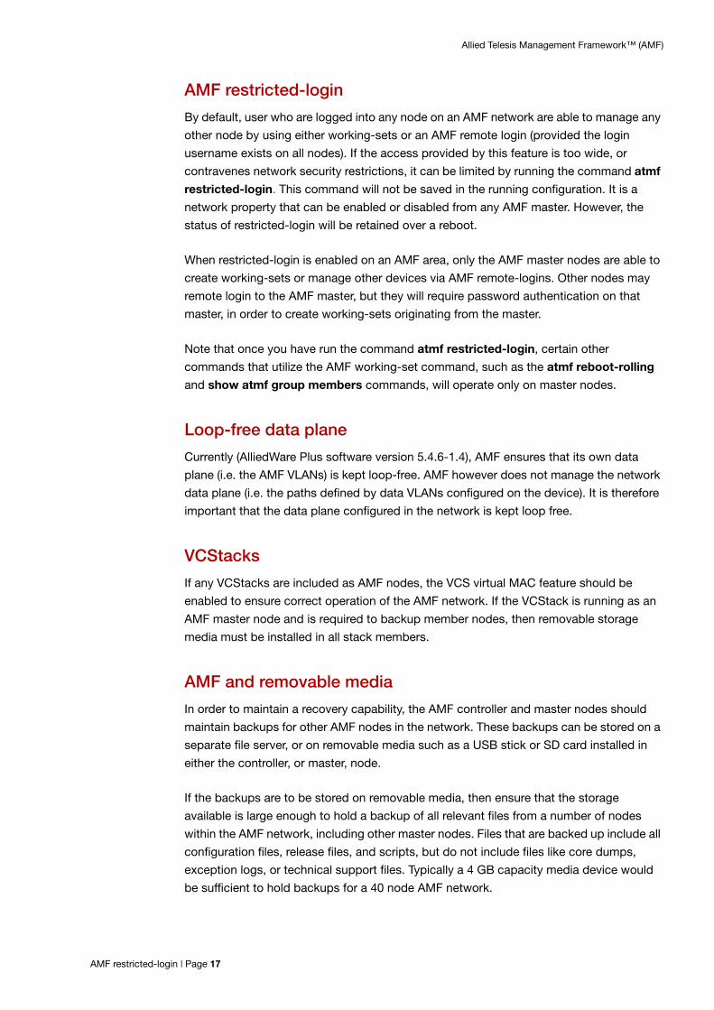
AMF restricted-login
By default, user who are logged into any node on an AMF network are able to manage any
other node by using either working-sets or an AMF remote login (provided the login
username exists on all nodes). If the access provided by this feature is too wide, or
contravenes network security restrictions, it can be limited by running the command atmf
restricted-login. This command will not be saved in the running configuration. It is a
network property that can be enabled or disabled from any AMF master. However, the
status of restricted-login will be retained over a reboot.
When restricted-login is enabled on an AMF area, only the AMF master nodes are able to
create working-sets or manage other devices via AMF remote-logins. Other nodes may
remote login to the AMF master, but they will require password authentication on that
master, in order to create working-sets originating from the master.
Note that once you have run the command atmf restricted-login, certain other
commands that utilize the AMF working-set command, such as the atmf reboot-rolling
and show atmf group members commands, will operate only on master nodes.
Loop-free data plane
Currently (AlliedWare Plus software version 5.4.6-1.4), AMF ensures that its own data
plane (i.e. the AMF VLANs) is kept loop-free. AMF however does not manage the network
data plane (i.e. the paths defined by data VLANs configured on the device). It is therefore
important that the data plane configured in the network is kept loop free.
VCStacks
If any VCStacks are included as AMF nodes, the VCS virtual MAC feature should be
enabled to ensure correct operation of the AMF network. If the VCStack is running as an
AMF master node and is required to backup member nodes, then removable storage
media must be installed in all stack members.
AMF and removable media
In order to maintain a recovery capability, the AMF controller and master nodes should
maintain backups for other AMF nodes in the network. These backups can be stored on a
separate file server, or on removable media such as a USB stick or SD card installed in
either the controller, or master, node.
If the backups are to be stored on removable media, then ensure that the storage
available is large enough to hold a backup of all relevant files from a number of nodes
within the AMF network, including other master nodes. Files that are backed up include all
configuration files, release files, and scripts, but do not include files like core dumps,
exception logs, or technical support files. Typically a 4 GB capacity media device would
be sufficient to hold backups for a 40 node AMF network.
AMF restricted-login | Page 17

Allied Telesis Management Framework™ (AMF)
When using dual CFCs in an SBx8100, a USB memory stick is required in both CFCs.
Similarly, if a VCStack is being used as the master node, all stack members will require
removable media to be installed.
AMF interaction with QoS and ACLs
It's important that ACL and QoS rules do not block the following traffic types:
any traffic on VLANs 4091 and 4092, because they are the default AMF control VLANs.
any Layer 3 traffic on 172.31.0.* or 172.31.128.*, because they are the default AMF
management traffic subnets.
packets with protocol type 0xfbae.
BPDU packets that use the MAC address 0180.c200.002e.
any IPv6 addresses in the range FD00:4154:4D46::/48, as these are used for inter-area
communication.
Note: The AMF control VLANs and AMF management subnets can be manually changed.
With AMF enabled, the number of ACLs available on the DC2552XS\L3, x930, x210, x230,
x310, x510, and x610 switches decreases by 1. If this is problematic and you are not
using AMF, you can disable AMF, which will allow the previous maximum number of ACLs.
Sharing AMF links with other network operations
AMF links have special significance within the AMF network. They are the links used to
carry the AMF management and control traffic flows. Moreover, the AMF software
includes its own algorithm for ensuring loop-free operation of the AMF management
VLANs that run over AMF links.
However, despite the special significance of AMF links, they are not used exclusively for
AMF communication, and are also able to participate in other aspects of the operation of
the network. Specifically, they can also carry data VLANs, and therefore transport all
manner of user data that is being exchanged within the network.
However, although AMF does ensure loop-free operation of the AMF management VLANs
that operate over its AMF links, it does not provide the same service to the data VLANs
(including the native vlan if present) that may also be configured to use these links. Users
are, therefore, responsible for protecting their data VLANs - either by explicitly avoiding
VLAN loops by either configuring EPSR, or by using the spanning tree protocol. In this
respect the following should be noted:
AMF coexists with spanning tree - so spanning tree will operate on AMF links, without
adversely affecting the operation of the AMF management VLANs.
There is no restriction regarding the use of EPSR with AMF. EPSR rings can coexist on
ports that are also configured with AMF links.
Page 18 | AMF interaction with QoS and ACLs

Allied Telesis Management Framework™ (AMF)
NTP and AMF
AMF uses NTP to synchronize the system clocks across nodes within the network. For
this to operate, one or more external NTP servers must be configured on the network,
preferably on the AMF Master.
The primary function of NTP within an AMF network is to ensure that nodes all have the
same time, so that date stamps on backups are consistent across member nodes within
the backup. In an AMF network that has multiple AMF master nodes, it is particularly
important to ensure that node recovery is performed with the most up-to-date backup.
It is a good idea to set the time zone to be the same on all AMF nodes.
Configuring NTP on the AMF network
On one or more (but not all) AMF nodes connected to the Internet, you should configure
three external NTP servers. The best nodes to configure this on are the AMF Masters or a
node directly connected to them.
Note: The AMF Masters are the preferred place to configure NTP, but this is not strictly required. You can configure non-AMF Masters to have external NTP servers, but behaviour degrades the further from the master it is. However, every directly connected node-pair will establish an NTP peer relationship which will allow the time to be synchronized back towards the AMF masters.
For example:
awplus(config)# ntp server 1.pool.ntp.org
awplus(config)# ntp server 2.pool.ntp.org
awplus(config)# ntp server 3.pool.ntp.org
You can check that nodes have synchronized with the NTP server using the show ntp
status command, for example:
Output 3: Output from the show ntp status command
awplus#show ntp statusassocid=0 status=0618 leap_none, sync_ntp, 1 event, no_sys_peer,system peer: 10.37.109.1:123system peer mode: clientleap indicator: 00stratum: 4log2 precision: -18root delay: 32.810root dispersion: 159.658reference ID: 10.37.109.1reference time: db5f5f4e.94ac8ebe Thu, Aug 18 2016 10:10:22.580system jitter: 0.482072clock jitter: 0.366clock wander: 0.247broadcast delay: 0.000symm. auth. delay: 0.000
NTP and AMF | Page 19

Allied Telesis Management Framework™ (AMF)
Node licensing
Master and controller
node license
AMF master and controller nodes are supported on selected Allied Telesis platforms. An
AMF license is required for each master or controller. For information about which
products can act as AMF master or controller nodes and the available licenses, see the
AlliedWare Plus Datasheet.
For the case of the SBx8100, only one AMF master or controller license is required, even if
two CFCs (Controller Fabric Cards) are installed. If the SBx8100 has two CFC cards
installed, then the license can be installed on one CFC card, and will be automatically
copied over to the other CFC card.
A VCStack needs to have consistent licensing on all stack members. Therefore, an AMF
master license would be required on all devices in an SBx908 or x930 stack. A stack will
form successfully even if the master license is present on some stack members, but not
others. However, if a master failover event occurs, and the new master unit in the VCStack
happens to be one that does not have the AMF master license installed, then the stack
will cease to operate as an AMF master. So, it is highly advisable to ensure that before a
VCStack goes live as an AMF master, the AMF master license is installed on all stack
members. See the Licensing Feature Overview and Configuration Guide for details.
When more than one AMF master node exists in an AMF area, it is important to know that
these master nodes operate completely independently of each other, and there is no
synchronization between them. For redundancy, an AMF area can have multiple master
nodes, each acting as a master for the area. However, because there is no
synchronization of status or data files between the masters; the behavior of a master node
is not affected by the presence of other master nodes.
AMF guestnode
The AMF guestnode feature provides an extension to AMF’s management capabilities by
providing a limited degree of management capability for devices (AMF guests) that either
do not run the AlliedWare Plus operating system or run a version that does not support
AMF. This capability offers AMF guests limited participation in an AMF network without
the need to modify their operating systems. Essentially, any device that has either an IPv4
or IPv6 address can become an AMF guest.
AMF nodes within the network can recognize the presence of an AMF guest either
dynamically, if it uses protocols such as DHCP or LLDP, or statically, from the switchport
atmf-guestlink command. Once recognized, the AMF node is then able to provide some,
albeit limited, level of support to these devices.
There is a limitation of one AMF guest per port on an AMF node. An AMF node can be
defined as being either an AMF controller, AMF master, or AMF member, AMF gateway, or
AMF guest.
Page 20 | Node licensing

Allied Telesis Management Framework™ (AMF)
Overview
An essential operating requirement of AMF guestnode configuration is that each AMF
guest directly connects to its own separate port on the AMF node with no intermediate
device in between.
AMF parent nodes are aware, from the AMF guestnode configuration commands, which
of their ports are connected to guest nodes. The AMF node then listens on those ports for
the transmission of specific frames (particularly DHCP and LLDP) in order to obtain
information about any of its attached AMF guest devices. Having discovered information
about an AMF guest, or by having its information configured statically, the AMF node
transmits this information to its local AMF master(s). The AMF guest information is then
accessible to users or by management tools that can access the AMF network
information database via the master(s).
Information about AMF guests is not distributed to the whole AMF network, but is instead
retained only on the directly connected node and its master(s). This avoids consuming
potentially large amounts of memory on the many nodes that may exist within a network.
Not all guest nodes are created equal
For some types of AMF guests, such as the TQ wireless access points, AMF has a more
detailed knowledge of the management interface, and is therefore able to perform specific
actions on those devices such as backup configuration, recover replacement units etc.
Others however, offer very little information that can be obtained by snooping, because
they do not transmit frames that provide useful AMF guest information. For these guest
node types, information needs to be statically configured on the port of the AMF node that
directly connects to the AMF guest.
AMF guest discovery
As stated in the previous section, AMF guests can be configured to be either static or
dynamic, depending on how the AMF node detects their existence. If the guest node uses
DHCP to learn an IP address dynamically, then the AMF nodes can use DHCP snooping
to learn the address that is allocated to the guest node. This process is termed dynamic IP
discovery.
If the AMF guest does not use DHCP to obtain an IP address, then the IPv4, or IPv6,
address of the AMF guest must be manually configured on the port of the AMF node that
connects to the AMF guest. This process is termed static IP discovery. Once an AMF
node is aware of an AMF guest’s IP address, it can use this to interrogate the device for its
MAC address.
Dynamic guest nodes
When AMF guests are configured for dynamic discovery, the switchport on the directly
connected AMF node is configured to use DHCP snooping to discover the AMF guest’s IP
and MAC addresses. Additionally, if the AMF guest supports LLDP and sends out LLDP
packets advertising information about itself, this information can be used to discover the
device MAC address, and other details. On devices that support LLDP-MED, this
information originates from that provided by the equipment supplier. For other devices,
information is retrieved from the descriptor string within the LLDP protocol.
AMF guestnode | Page 21

Allied Telesis Management Framework™ (AMF)
Note that dynamic discovery is only available when using IPv4. For IPv6 networking, static
IP discovery must be used. Also note, that an IPv4 address is required on the VLAN
interface on the parent AMF node in order for dynamic discovery to work.
Static AMF guests
Usually, AMF guests configured for static IP discovery do not support protocols such as
DHCP or LLDP, and therefore offer the AMF nodes little information to discover their IP
addresses etc. For these nodes, information such as IP addresses must be statically
configured on the port of the AMF node that connects to the AMF guest. Note that static
IP discovery must also be used on AMF guests, such as routers and wireless access
points, because these devices can have many connections to further downstream devices
each of which can have one or more IP addresses.
Note that if an AMF guest is statically configured but is also using DHCP and or LLDP and
there is a difference between the static and dynamic addresses, the static address will be
used.
Also note an AMF guest that has downstream devices with their own IP addresses —such
as routers or wireless access points— must have its IP address statically configured.
AMF functionality supported by AMF guests
The degree to which AMF management capability is extended to an individual AMF guest
depends on the nature of the AMF guest as defined by its modeltype.
By default, the minimum management functionality provided to an AMF guest under the
AMF management umbrella is basic topology reporting. At a minimum, AMF will track and
report an AMF guest's network activity recorded at the link level. Whatever information is
obtained about the AMF guest and its operational status will be stored in an AMF device
database and can be viewed by users.
For some AMF guest types however, device-specific support capability is included in
AMF. If the AMF network discovers that one of these advanced-support devices is
connected, then it enables the user to carry out more management operations on that
AMF guest.
AMF management capability varies as defined by its AMF guest model type. An AMF
guest model type is defined using the modeltype command, and can be one of the
following:
TQ access points
Alliedware devices
AlliedWare Plus devices
Other devices
Page 22 | AMF guestnode

Allied Telesis Management Framework™ (AMF)
TQ access points
This model type applies to the Allied Telesis TQ series of wireless access points. It is
presently the model type that offers the widest (AMF guest) support under AMF.
Management support for TQ guest nodes extends to operational status monitoring at the
link and network levels. AMF Master nodes will also backup configuration files for TQ
guest nodes, and manual recovery of configuration is also supported to enable easier
reconfiguration of replacement TQ guest nodes.
Notes: AMF Guest backup of TQ APs may fail if the APs are running in managed mode. If this happens, log in to the TQ and disable managed mode, then reboot. Guest backup of TQ APs may fail if there is a user logged on to the AP GUI. Reliable AMF backup of TQ AP guest devices will only occur with TQ firmware release 3.2.1.a02 and later.
AlliedWare devices
This model type offers additional support for Allied Telesis devices that are running the
legacy AlliedWare operating system, which does not support AMF. This support is limited
to operational status monitoring at the link and network levels.
AlliedWare Plus devices
This model type offers support for devices that are running the Allied Telesis AlliedWare
Plus operating system, but are not capable of running AMF. This support is limited to
operational status monitoring at the link and network levels.
Other devices This model type is intended for devices that do not fit into any of the above categories.
Support is limited to operational status monitoring at the link and network levels.
AMF guest configuration
There are two components of AMF guest configuration:
guest-class configuration, and
guest-link configuration
Guest-class configuration
Guest-classes are used to set up the general parameters for a class of AMF guest
devices. Each guest-class is a profile that can be assigned to multiple AMF guests.
Guest-classes are modal templates that can be applied to selected AMF guest types.
Once you have created a guest-class, you can select it by entering its mode. From here,
you can then configure a further set of operational settings specifically for this guest-
class. These settings can then all be applied to an AMF guest link by running the
switchport atmf-guestlink command.
AMF guest configuration | Page 23

Allied Telesis Management Framework™ (AMF)
The following settings can be configured from within each guest-class mode:
Discovery method
The discovery method can be either static or dynamic. If unconfigured, the command will
apply its default setting of dynamic. AlliedWare Plus router platforms do not support
DHCP Snooping or LLDP. Therefore, dynamic guest-class discovery is not supported on
these products. Before running the command switchport atmf-guestlink a guest-class
with a discovery method of static must be configured.
HTTP enable This parameter is reserved for future use and is currently inactive.
Model type This parameter can be set to one of alliedware, alliedware+, tq, or other. If unconfigured it
will apply the default of other.
Guest port, user name,
and password
The username and password used for devices supporting extended AMF guest
functionality.
Configuration methodology
The methodology applied in the following example assigns an AMF guest configuration to
a switchport of an AMF node, then associates the AMF guest with a guest-class profile.
This will determine the method AMF uses to interrogate the AMF guest.
The following steps are used to define a guest-class:
Step 1: Define a guest-class name and enter the guest configuration mode for that guest-class.
Step 2: Configure parameters for the new class.
To configure a port on a parent node (named Parent-Node1 in this example) to know that
it is connected to a guest node, simply configure the port as a guest link.
Parent-Node1(config)
atmf guest-class TQ4600Create a guest-class named TQ4600 and enter the guest-class configuration mode for that guest-class.
Parent-Node1(config-atmf-guest)
Parent-Node1(config-atmf-guest)
modeltype tqSelect the modeltype for the guest-class to be a tq
Parent-Node1(config-atmf-guest)
username manager password <tq46-guestpass>
Define a password for the TQ4600 of tq46-guestpass
Page 24 | AMF guest configuration

Allied Telesis Management Framework™ (AMF)
Step 3: Configure port2.1.1 to be a guestlink.
Note: An IPv4 address is required on the VLAN interface on the parent AMF node in order for dynamic discovery to work.
Example 1
Step 1 Create the guest-class name FireSensor with a modeltype of other and set it to be
statically detected:
Step 2 Associate the guest-class FireSensor with the port2.1.7
The guest-class that is specified in this command must have already been created by
using the atmf guest-class command. If the guest-class name in the command does not
correspond to an already-defined guest-class, then the command will return an error. Also
note that names of guest-classes are case-sensitive.
Parent-Node1(config)
interface port2.1.1Select port2.1.1 to configure
Parent-Node1(config-if)
switchport atmf-guestlinkConfigure the port to be a guest link.
Parent-Node1(config)
atmf guest-class FireSensorCreate a guest-class named FireSensor and enter the guest-class configuration mode for that guest-class.
Parent-Node1(config-atmf-guest)
modeltype otherSet the modeltype to other
Parent-Node1(config-atmf-guest)
discovery staticSet the device to be statically configured
Parent-Node1(config)
interface port2.1.7Select port2.1.7 to configure
Parent-Node1(config-if)
switchport atmf-guestlink class FireSensor
ip 10.1.2.3
Configure the port to be a guestlink for the guest type FireSensor with the IP address 10.21.2.3.
AMF guest configuration | Page 25
Allied Telesis Management Framework™ (AMF)
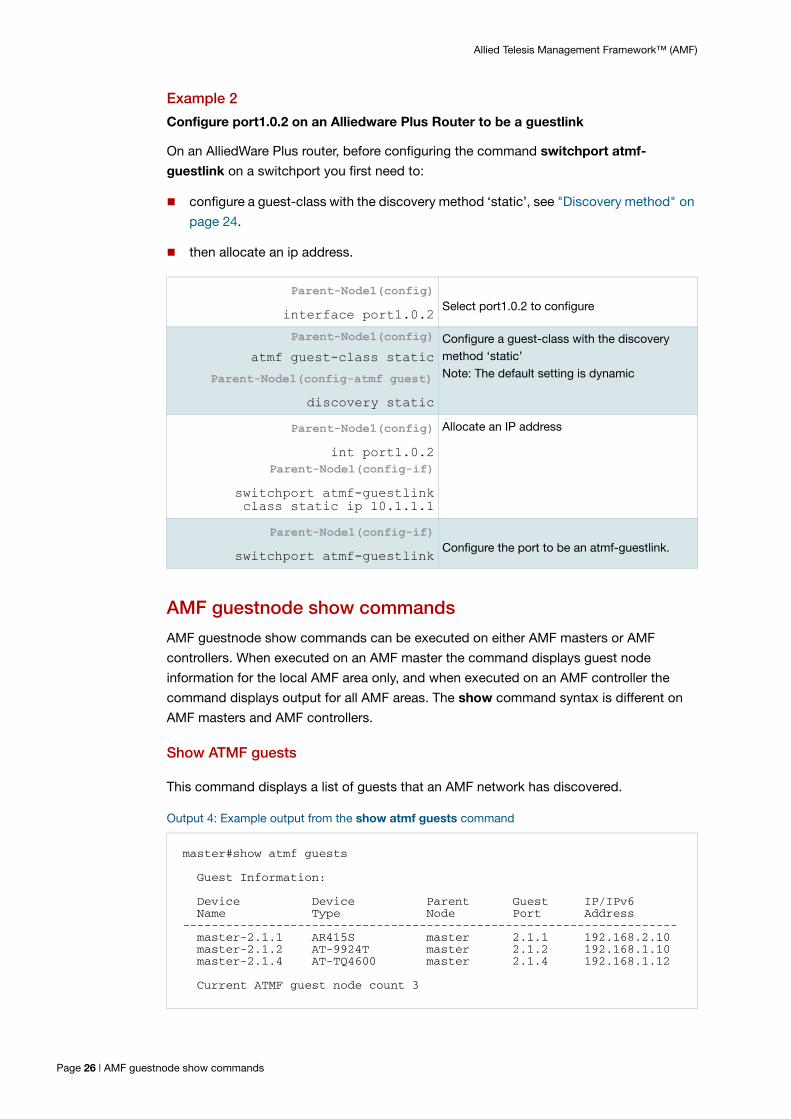
Example 2
Configure port1.0.2 on an Alliedware Plus Router to be a guestlink
On an AlliedWare Plus router, before configuring the command switchport atmf-
guestlink on a switchport you first need to:
configure a guest-class with the discovery method ‘static’, see "Discovery method" on
page 24.
then allocate an ip address.
AMF guestnode show commands
AMF guestnode show commands can be executed on either AMF masters or AMF
controllers. When executed on an AMF master the command displays guest node
information for the local AMF area only, and when executed on an AMF controller the
command displays output for all AMF areas. The show command syntax is different on
AMF masters and AMF controllers.
Show ATMF guests
This command displays a list of guests that an AMF network has discovered.
Output 4: Example output from the show atmf guests command
Parent-Node1(config)
interface port1.0.2Select port1.0.2 to configure
Parent-Node1(config)
atmf guest-class static
Parent-Node1(config-atmf guest)
discovery static
Configure a guest-class with the discovery method ‘static’Note: The default setting is dynamic
Parent-Node1(config)
int port1.0.2Parent-Node1(config-if)
switchport atmf-guestlink class static ip 10.1.1.1
Allocate an IP address
Parent-Node1(config-if)
switchport atmf-guestlinkConfigure the port to be an atmf-guestlink.
master#show atmf guests
Guest Information:
Device Device Parent Guest IP/IPv6 Name Type Node Port Address--------------------------------------------------------------------- master-2.1.1 AR415S master 2.1.1 192.168.2.10 master-2.1.2 AT-9924T master 2.1.2 192.168.1.10 master-2.1.4 AT-TQ4600 master 2.1.4 192.168.1.12
Current ATMF guest node count 3
Page 26 | AMF guestnode show commands

Allied Telesis Management Framework™ (AMF)
Show ATMF guests detail
This command displays the details of each discovered guest node.
Output 5: Example output from the show atmf guests detail command
Figure 5: Parameter Descriptions from the show atmf guests command
PARAMETER DESCRIPTION
Device Name The name assigned for this device within the AMF network. It could be a name that is discovered from the device, or failing that, a name that is auto-assigned by AMF. The auto-assigned name consists of <parent node name>-<attached port number>
Device Type This is the product name of the guest node and is discovered from the device. If no device Type can be discovered, then the model name configured on the guest-class assigned to the connected port is used.
Parent Node The AMF member name of the AMF member that directly connects to the guest node.
Guest Port The port, on the parent node that directly connects to the guest node.
IP/IPv6 Address The address discovered from the node, or statically configured on the parent node's attached port.
master#show atmf guests detail
ATMF Guest Node Information:
Node Name : masterPort Name : port2.1.1Ifindex : 6101Guest Description : master-2.1.1Device Type : AR415SBackup Supported : NoMAC Address : 0000.cd1d.b114IP Address : 192.168.2.10IPv6 Address : Not SetHTTP Port : 0Firmware Version : 2.9.2-09
Node Name : masterPort Name : port2.1.2Ifindex : 6102Guest Description : master-2.1.2Device Type : AT-9924TBackup Supported : NoMAC Address : 0000.cd24.023aIP Address : 192.168.1.10IPv6 Address : Not SetHTTP Port : 0Firmware Version : 2.9.1-15
Node Name : masterPort Name : port2.1.4Ifindex : 6104Guest Description : master-2.1.4Device Type : AT-TQ3200Backup Supported : YesMAC Address : 001a.eb85.fd60IP Address : 192.168.1.12IPv6 Address : Not SetHTTP Port : 0Firmware Version : 3.2.1 A02
AMF guestnode show commands | Page 27

Allied Telesis Management Framework™ (AMF)
Show ATMF links guests
This command shows the details of guest links on the parent node.
Output 6: Output from the show atmf links guests command
Figure 6: Parameter Descriptions from the show atmf guests detail command
PARAMETER DESCRIPTION
Node Name The AMF device that directly connects to the guest node, i.e. the parent node.
Port Name The port on the parent node that directly connects to the guest node.
Ifindex An internal index number that maps to the port number of the guest’s parent node.
Guest
DescriptionThis parameter may display either a user supplied description that has been manually entered during the interface configuration, or alternatively may revert to its default of displaying the AMF parent node plus the port number that connects it to the guest.
Device Type A device type name that is extracted from the device.
Backup Supported Indicates whether AMF is able to backup this device.
MAC Address The MAC address of the guest node.
IP Address The IP address of the guest node.
IPv6 Address The IPv6 address of the guest node.
HTTP Port The HTTP port enables you to specify a port when enabling HTTP to allow a URL for the HTTP user interface of a guest node. This is determined by the http-enable <port> command.
Firmware Version The firmware level that the guest is running, as extracted from the guest node.
master#show atmf links guest
Guest Link Information:
DC = Discovery configuration S = static D = dynamic
Local Guest Model MAC IP / IPv6Port Class Type DC Address Address---------------------------------------------------------------------2.1.1 alliedware Alliedware S 0000.cd1d.b114 192.168.2.102.1.2 awdyn Alliedware D 0000.cd24.023a 192.168.1.102.1.4 TQ TQ D 001a.eb85.fd60 192.168.1.122.1.6 FireSensor Other S - 2001:af34:93::fe92.1.7 - Other D - -
Page 28 | AMF guestnode show commands
Allied Telesis Management Framework™ (AMF)
Renaming your AMF network
In software versions prior to 5.4.6-1.x, if you renamed the AMF network on an AlliedWare
Plus device, we recommended you reboot your device. Version 5.4.6-1.x removes the
need to reboot. To rename the AMF network, use the command:
node_1(config)# atmf network-name <new-name>
AMF support for x600 Series switches
AMF networks that are running version 5.4.6-1.x or later can be more seamlessly
integrated with AlliedWare Plus x600 Series switches, as long as the x600 Series switch is
running version 5.4.2-3.14 or later.
The x600 Series switch must be directly connected to an AMF node that is running
5.4.6-1.x or later.
The x600 Series switch provides the following information to the AMF node that it is
connected to:
MAC address of the port connected to the AMF node
IPv4 address
IPv6 address
name/type of the device (Allied Telesis x600)
name of the current firmware
version of the current firmware
configuration name
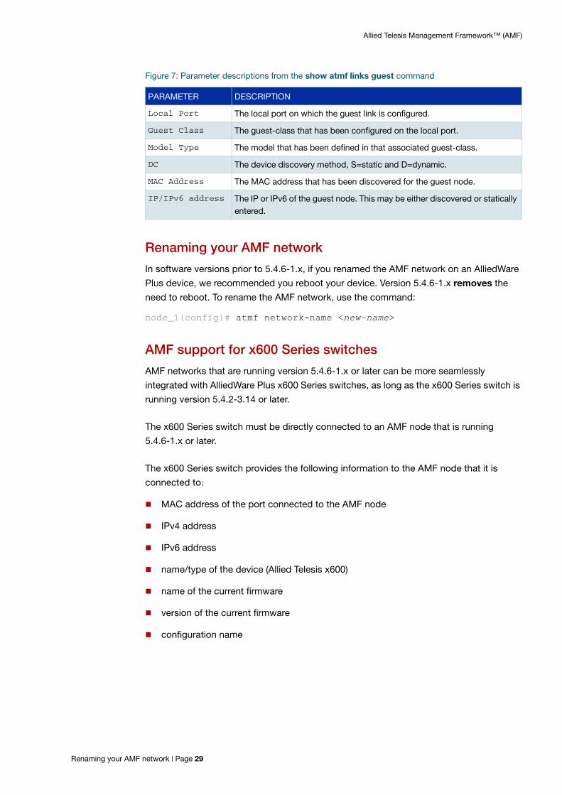
Figure 7: Parameter descriptions from the show atmf links guest command
PARAMETER DESCRIPTION
Local Port The local port on which the guest link is configured.
Guest Class The guest-class that has been configured on the local port.
Model Type The model that has been defined in that associated guest-class.
DC The device discovery method, S=static and D=dynamic.
MAC Address The MAC address that has been discovered for the guest node.
IP/IPv6 address The IP or IPv6 of the guest node. This may be either discovered or statically entered.
Renaming your AMF network | Page 29

Allied Telesis Management Framework™ (AMF)
Earlier software versions made most of this information available from x600 Series
switches, but it was necessary to configure the x600 as an AMF guestnode (so it needed
to be configured with DHCP and/or LLDP). With version 5.4.2-3.16 or later, as soon the
x600 is connected to an appropriately configured port of an AMF node, it is immediately
integrated into the AMF network.
To configure the new functionality, use the following steps.
The x600 Series switch must be running version 5.4.2-3.16 or later.
On the AMF node to which the x600 Series switch is connected, configure the link to the
x600, using the command:
node_1(config-if)# switchport atmf-agentlink
On the AMF node to which the x600 Series switch is connected, you can see the details of
the x600 by running the following command:
node_1# show atmf links guest detail
Step 1. Upgrade the software version on the x600 Series switch
Step 2. Configure the link to the x600 Series switch
Step 3. Monitor the x600 Series switch
Page 30 | AMF support for x600 Series switches
Allied Telesis Management Framework™ (AMF)
AMF Configuration This section presents a series of examples explaining how to configure an AMF network.
Example - Configuring a simple stand-alone area
The following configuration example uses a simplified network to explain the basic steps
required to configure AMF.
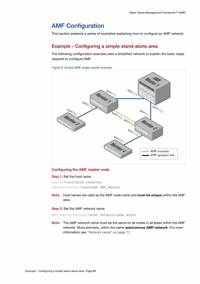
Figure 8: Simple AMF single master example
Configuring the AMF master node
Step 1: Set the host name
awplus#configure terminal
awplus(config)#hostname AMF_Master
Note: Host names are used as the AMF node name and must be unique within the AMF area.
Step 2: Set the AMF network name
AMF_Master(config)#atmf network-name atmf1
Note: The AMF network name must be the same on all nodes in all areas within the AMF network. More precisely, within the same autonomous AMF network. For more information see "Network name" on page 11.
Member 1
Member 2
Member 4
Member 3
port1.0.1
AMF crosslinkAMF up/down link
port1.1.3
port1.1.3port1.0.1
port1.1.2 port1.1.2
port1.1.1
port1.1.2
port1.1.1
port1.1.1
AMFMaster 1
Example - Configuring a simple stand-alone area | Page 31

Allied Telesis Management Framework™ (AMF)
Step 3: Configure the switch to be the AMF master
AMF_Master(config)#atmf master
On standalone devices one master license is required per device. In the case of a
SBx8100 chassis with dual CFC controller cards fitted - this is still considered a single
device, and so only a single AMF master license is required. If the SBx8100 has two
CFC cards installed, then the licence can be installed on one CFC card, and will be
automatically copied over to the other CFC card.
On VCStacks, prior to software version 5.4.5, an AMF master license was required for
each VCStack member. From 5.4.5 onwards, the licensing has been relaxed, and only
a single AMF master license is required per VCStack. However, this license needs to
be installed on each stack member.
Step 4: Configure the data VLANs
AMF_Master(config)#vlan database
AMF_Master(config-vlan)# vlan 2
AMF_Master(config-vlan)# vlan 3
AMF_Master(config-vlan)# exit
Step 5: Configure ports as AMF-links
AMF_Master(config)#interface port1.1.1-1.1.2
AMF_Master(config-if)#switchport atmf-link
Step 6: Configure data VLANs on AMF-links as required
AMF_Master(config-if)#switchport trunk allowed vlan add 2-3
AMF_Master(config-if)#switchport trunk native vlan none
Step 7: Save the configuration and reboot the switch.
AMF_Master#copy running-config startup-config
Building configuration...[OK]
AMF_Master#reload
Note: You must reboot the device to ensure that the AMF network name takes effect.
Configuring the first two member nodes (Member1 and Member2)
The configuration of each of the member nodes does not differ vastly. However, the set of
ports used for AMF links is not the same on all the members. Member1 and Member2
both use one set of ports, while Member3 and Member4 use another set. So, we will look
first at the configuration required on Member1 and Member2, and then consider the
configuration used on Member3 and Member4.
Configure Member1
Step 1: Set the host name
awplus#configure terminal
awplus(config)#)hostname Member1
Page 32 | Example - Configuring a simple stand-alone area
Allied Telesis Management Framework™ (AMF)
Note: Host names that are used as the node name for AMF nodes MUST BE UNIQUE within the AMF area. Each of the member nodes needs to be given a different hostname, e.g. Member1, Member2. Host names must be unique within an AMF area.
Step 2: Set the AMF network name
Member1(config)#atmf network-name atmf1
Note: Note that the AMF network name must be the same on all nodes on all AMF areas within the AMF network.
Step 3: Configure the data VLANs
Member1(config)#vlan database
Member1(config-vlan)#vlan 2-3
Step 4: Configure ports as AMF-links
Member1(config)#interface port1.1.1-1.1.3
Member1(config-if)#switchport atmf-link
Step 5: Configure data VLANs on the AMF-links as required
Member1(config-if)#switchport trunk allowed vlan add 2-3
AMF_Master(config-if)#switchport trunk native vlan none
Step 6: Configure an AMF-crosslink
Member1(config)#interface port1.1.2
Member1(config-if)#switchport atmf-crosslink
Member1(config-if)#switchport trunk native vlan none
Note: AMF links and crosslinks do not need to be configured with data VLANs and can be used solely to provide redundant links in the AMF management VLAN.
Step 7: Save the configuration and reboot the switch.
Member1#copy running-config startup-config
Member1#reload
Note: You must reboot the device to ensure that the AMF network name takes effect.
Configure Member2
Because members 1 and 2 have the same port configuration, you can repeat the steps
used to configure Member1 but set the hostname to be Member2.
Configure Member 3
Step 1: Set the host name
awplus#configure terminal
awplus(config)#hostname Member3
Note: Host names are used as the node name for AMF nodes and MUST BE UNIQUE within the AMF area. So, each of the member nodes needs to be given a different hostname, e.g. Member3, Member4.
Example - Configuring a simple stand-alone area | Page 33

Allied Telesis Management Framework™ (AMF)
Step 2: Set the AMF network name
Member3(config)#atmf network-name atmf1
Note: The AMF network name must be the same on all nodes in all areas within the AMF network.
Step 3: Configure the data VLANs
Member3(config)#vlan database
Member3(config-vlan)#vlan 2-3
Step 4: Configure ports as AMF-links
Member3(config)#interface port1.0.1
Member3(config-if)#switchport atmf-link
Step 5: Configure data VLANs on the AMF-links as required
Member3(config-if)# switchport trunk allowed vlan add 2-3
AMF_Master(config-if)#switchport trunk native vlan none
Step 6: Save the configuration and reboot the switch
Member3#copy running-config startup-config
Member3#reload
Note: You must reboot the device to ensure that the AMF network name takes effect.
Configure Member4
Because members 3 and 4 have the same port configuration, you can repeat the steps
used to configure Member3 but set the hostname to be Member4
Verifying the AMF Network
To check that all nodes have joined the AMF network use the show atmf command with
the summary parameter. You can run this command from any node in an AMF network.
Output 7: Checking AMF configuration using the show atmf summary command
The Current AMF Nodes field in the output above shows that all 5 nodes have joined the
AMF network.
AMF_Master#show atmf summaryATMF Summary Information:ATMF Status : EnabledNetwork Name : atmf1Node Name : AMF_MasterRole : MasterCurrent ATMF Nodes : 5AMF_Master#
Page 34 | Example - Configuring a simple stand-alone area

Allied Telesis Management Framework™ (AMF)
Use the show atmf nodes command to check information on individual nodes:
Output 8: Output from the show atmf nodes command
Note: The Parent field in the output above refers to the parent domain and not the upstream device. In the example output above, Member2 is the domain controller for the parent domain for Member3 and Member4.
Use the show atmf links command to check information on individual AMF links:
Output 9: Checking output with the show atmf links command
AMF tunneling (virtual-links)
AMF tunneling enables you to extend your local uplinks and downlinks across a wide area
network. The tunneled data is wrapped in a Layer 3 IP packet for transmission across a
wide area IP network. A simple AMF tunnel is shown in Figure 9 on page 36. Switches 1
and 2 encapsulate the Layer 2 AMF uplink and downlink data and wrap this inside a Layer
3 IP packet to enable it to traverse an IP Network. Routers 1 and 2 (and any other routers
within the cloud) perform a conventional routing function, reading the IP addresses of the
tunneled packets and forwarding them to their destination.
Once connected through the tunnel, the remote AMF members will have the same AMF
capabilities as a directly connected AMF member.
AMF_Master#show atmf nodesNode Information: * = Local device SC = Switch Configuration: C = Chassis S = Stackable N = StandaloneNode Device ATMF NodeName Type Master SC Parent Depth---------------------------------------------------------------------* AMF_Master AT-SBx81CFC400 Y C none 0 Member1 SwitchBlade x908 N S AMF_Master 1 Member2 SwitchBlade x908 N S AMF_Master 1 Member4 x510-52GTX N S Member2 2 Member3 x510-52GTX N S Member2 2 Current ATMF node count 5
switch1# show atmf links
ATMF Links Brief:
Local Link Port ATMF Adjacent Adjacent LinkPort Type Status State Node Ifindex State-----------------------------------------------------------------------------sa1 Crosslink Up TwoWay Building_1 4501 Forwarding1.1.1 Downlink Up Full Bld1_Floor_1 5001 Forwarding1.1.2 Downlink Up Full Bld1_Floor_2 5003 Forwarding1.1.3 Downlink Up Full Bld2_Floor_1 6101 Forwarding1.1.4 Crosslink Down Init *switch3 Blocking
* = provisioned
AMF tunneling (virtual-links) | Page 35

Allied Telesis Management Framework™ (AMF)
Figure 9: AMF virtual-link
Configuring a virtual-link
Configuration involves specifying the following:
local tunnel ID
local IP address
remote tunnel ID
remote IP address
AMF hostname: Host-A
IPNetwork
Switch 1
Switch 2 AMF hostname: Host-B AMF Crosslink(Layer 2 connectivity)
AMF Up/Downlink(Layer 2 connectivity)
Router 1
Router 2
192.168.1.1
192.168.2.1192.168.2.1 192.168.2.1
192.168.1.1 192.168.1.1
Tunnel ID = 2Tunnel remote ID = 1
Tunnel ID = 1Tunnel remote ID = 2
Tunneled PacketAMF Up/Down Link
Page 36 | AMF tunneling (virtual-links)
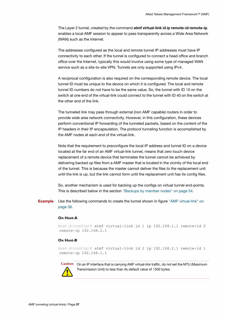
Allied Telesis Management Framework™ (AMF)
The Layer 2 tunnel, created by the command atmf virtual-link id ip remote-id remote-ip,
enables a local AMF session to appear to pass transparently across a Wide Area Network
(WAN) such as the Internet.
The addresses configured as the local and remote tunnel IP addresses must have IP
connectivity to each other. If the tunnel is configured to connect a head office and branch
office over the Internet, typically this would involve using some type of managed WAN
service such as a site-to-site VPN. Tunnels are only supported using IPv4.
A reciprocal configuration is also required on the corresponding remote device. The local
tunnel ID must be unique to the device on which it is configured. The local and remote
tunnel ID numbers do not have to be the same value. So, the tunnel with ID 10 on the
switch at one end of the virtual-link could connect to the tunnel with ID 40 on the switch at
the other end of the link.
The tunneled link may pass through external (non AMF capable) routers in order to
provide wide area network connectivity. However, in this configuration, these devices
perform conventional IP forwarding of the tunneled packets, based on the content of the
IP headers in their IP encapsulation. The protocol tunneling function is accomplished by
the AMF nodes at each end of the virtual-link.
Note that the requirement to preconfigure the local IP address and tunnel ID on a device
located at the far end of an AMF virtual-link tunnel, means that zero touch device
replacement of a remote device that terminates the tunnel cannot be achieved by
delivering backed up files from a AMF master that is located in the vicinity of the local end
of the tunnel. This is because the master cannot deliver the files to the replacement unit
until the link is up, but the link cannot form until the replacement unit has its config files.
So, another mechanism is used for backing up the configs on virtual tunnel end-points.
This is described below in the section "Backups by member nodes" on page 54.
Example Use the following commands to create the tunnel shown in figure "AMF virtual-link" on
page 36.
On Host-A
Host-A(config)# atmf virtual-link id 1 ip 192.168.1.1 remote-id 2 remote-ip 192.168.2.1
On Host-B
Host-B(config)# atmf virtual-link id 2 ip 192.168.2.1 remote-id 1 remote-ip 192.168.1.1
Caution On an IP interface that is carrying AMF virtual-link traffic, do not set the MTU (Maximum Transmission Unit) to less than its default value of 1500 bytes.
AMF tunneling (virtual-links) | Page 37

Allied Telesis Management Framework™ (AMF)
Prioritizing the tunneled traffic
The traffic that is carried in the tunnel includes AMF management information. It is
therefore critical that this information is conveyed to the portion of the network that lies at
the remote end of the tunnel. Accordingly, the traffic that passes through the tunnel should
be given a high QoS priority, so that it will not be lost if other user traffic causes
congestion.
There are two key places in the path where we need to consider prioritization of the tunnel
traffic:
1. When the tunneled traffic passes through any devices that lie between the tunnel endpoint and the wide area network.
2. When the tunneled traffic arrives at the endpoint device, and needs to go up to its CPU.
Prioritizing tunnel traffic passing through other switches
As the tunnel passes through other switches that lie between the tunnel endpoint and the
WAN, the traffic destined for the tunnel will be hardware forwarded by these switches. The
tasks that are required to increase the priority of that hardware forwarding are:
recognise the tunnel destined traffic.
assign this traffic to a high-priority queue on the egress port.
insert a priority tag in the VLAN header of the tunnel destined packets.
insert a priority tag into the IP header of the tunnel destined packets.
Recognising the tunnel traffic
In the illustration in "AMF virtual-link" on page 36, the tunnel destined traffic consists of IP
packets between 192.168.1.1 and 192.168.2.1.
Consider a switch located between Switch1 and Router1, with its port1.0.1 interface
connected to Router1 and its port1.0.2 interface connected to Switch1.
This switch needs to prioritize the tunnel destined traffic in both directions - from Switch1
to Switch2 and from Switch2 to Switch1.
Therefore, it needs to look for traffic with:
Source IP 192.168.1.1 and Destination IP 192.168.2.1
Source IP 192.168.2.1 and Destination IP 192.168.1.1
These two sets of traffic can be classified by matching with the following ACLs:
access-list hardware vlinkdown
permit ip 192.168.1.1/32 ip 192.168.2.1/32
access-list hardware vlinkup
permit ip 192.168.2.1/32 ip 192.168.1.1/32
Page 38 | AMF tunneling (virtual-links)

Allied Telesis Management Framework™ (AMF)
Assigning the traffic to a high-priority queue on the egress port
There are a few configuration steps required to achieve this. A classmap needs to be
created for each tunnel direction, that matches traffic for that tunnel direction:
class-map vlinkup match access-group vlinkup
class-map vlinkdown match access-group vlinkdown
A policy map needs to be created for each tunnel direction, that takes the traffic matching
the appropriate classmap, and puts that traffic into a high-priority egress queue (in this
case, queue 5).
policy-map vlinkup
class default
class vlinkup
remark new-cos 5 internal
policy-map vlinkdown
class default
class vlinkdown
remark new-cos 5 internal
The appropriate policy map needs to be applied to the port on which the tunnel traffic in
the given direction arrives.
int port1.0.1
service-policy input vlinkup
int port1.0.2
service-policy input vlinkdown
Insert a priority tag in the VLAN header of tunnel destined packets
This optional action might be useful where additional switches exist between the AMF
tunnel endpoint and the WAN and that these switches only support CoS-based
prioritization.
If the CoS value in the tunnel packets is set to a high value, then typically, these additional
switches will be able to give that traffic high priority.
The configuration required to mark the CoS values in these frames is simply to change the
lines "remark new-cos 5 internal" in the configuration above to “remark new-cos
5 both”.
In this way, the frames are sent to a high-priority egress queue on the switch with the QoS
config and the CoS value in the frames' VLAN header is marked with the value 5.
AMF tunneling (virtual-links) | Page 39

Allied Telesis Management Framework™ (AMF)
Insert a priority tag in the IP header of tunnel destined packets
Again, this is an optional action. If the devices in the wide-area network are configured to
prioritize packets based on the DSCP value in their IP headers, then configuring a high-
priority value in DSCP fields of the tunnel packets could be worthwhile. In general, WAN
devices are not configured to prioritize based on DSCP, and certainly it cannot be
expected on the Internet. But, in the case of a private WAN that is configured with a DSCP
prioritization scheme, then the following configuration will be of value:
Add the line:
remark-map bandwidth-class green to new-dscp 46
to the class configuration in each policy map.
Prioritizing the tunnel traffic to the CPU of the receiving endpoint
When the tunneled traffic arrives at the end-point AMF member, it needs to go up to the
CPU of that device to be processed. If a high rate of traffic is arriving at that device, then
the link up to the CPU may be oversubscribed, and the tunnel traffic will need to be
prioritized to make sure it is not dropped due to the congestion.
The configuration for prioritizing the tunnel traffic up to the CPU is very similar to that for
prioritizing the traffic being forwarded in the tunnel. The main difference is that only one
direction of traffic (namely, traffic to the end-point device) needs to be prioritized.
For example, on Switch1, it is necessary only to match the traffic coming towards it from
Switch2:
access-list hardware incomingTunnel
permit ip 192.168.2.1/32 ip 192.168.1.1/32
From there, the rest of the configuration is essentially the same as the through-traffic
prioritization case:
policy-map incomingTunnel
classmap incomingTunnel
match access-group incomingTunnel
class default
class incomingTunnel
remark new-cos 5 internal
int port1.0.1
service-policy input incomingTunnel
Page 40 | Prioritizing the tunnel traffic to the CPU of the receiving endpoint

Allied Telesis Management Framework™ (AMF)
The Concept of AMF Areas
AMF is a highly scalable framework, designed to unify the management of very large
networks that can extend to over 7,000 nodes.
The inherent value of AMF is the capability to embed management intelligence into
network nodes. This enables them to work cooperatively to automate network
management tasks. As a result, devices within an AMF region of operation need to
maintain a reasonable degree of knowledge of all other devices in that region. So, when
operating on the scale of thousands of nodes, it is necessary to apply some structure on
the Framework, to divide it into separated operating regions. This way, strong integration
can be maintained between nodes within a region, but the coupling between nodes in
different regions can be considerably reduced.
This is achieved in AMF by dividing a network into regions known as AMF areas.
Each AMF area consists of one or more master nodes, and a set of member nodes. The
masters and members within an area operate in a unified fashion, but have no interaction
with masters or members of other regions.
Coordinating the AMF network as a whole are up to eight controller nodes, each of which
can communicate with the master nodes in other areas. All the controller nodes may be
configured either to communicate with the masters in all other areas, or in order to spread
the load across the controllers, different controllers could be configured to communicate
with the masters within selected sets of areas.
The area that contains the controller(s) is called the core area. The controllers are not
necessarily the master nodes of their own local area. Configuring a node to be a controller
is independent from configuring a node to be a master. So, the master node(s) of the core
area can be quite separate from the controller(s) within that area. Or the controller(s) that
exist in that area. could also be configured to be master(s).
Configuring an AMF controller
To set up a node as an AMF controller, it first needs to have an AMF controller license
installed on it. Then it can be configured to be a controller by using the command:
atmf controller
The area to which it belongs needs to be given a name and an ID number:
atmf area <area-name> id <1-126> [local]
The parameter local indicates that this command is specifying the name and ID number
of the area in which the controller resides.
Configuring an AMF controller | Page 41

Allied Telesis Management Framework™ (AMF)
The controller needs to be informed of the identities of the areas it is controlling, and to be
given passwords for authenticating its communication to masters in those areas.
So, the following commands need to be configured on the controller, for each of the areas
it controls:
atmf area <area-name> id <1-126>
atmf area <area-name> password [8] <password>
The corresponding password also needs to be configured on master nodes and gateway
nodes (see below for an explanation of gateway nodes) in each of those areas.
In addition the controller will need configuration relating to the backing up of master
nodes in the controlled areas, as described in the section "Controlling the backup
behaviour of controller and master nodes" on page 58.
Connections from AMF controllers to the other areas
For an AMF controller to communicate with the other areas that comprise the network, it
needs AMF links into those areas. The core area has a link to each of the other areas in the
network. The other areas do not have links to each other, so the only inter-area links are
those from the core area to the other areas.
The links from the core area to another area are referred to as area links. These links may
be direct connections between neighboring nodes, or they may be virtual-links; either is
quite valid. The end points of the area links can be any nodes within the two areas that are
being connected. There is no requirement that the area link terminate on a controller or
master node, and similarly there is no rule that the area link can't terminate on a controller
or master node.
The devices at each end of the area link are referred to as gateway nodes, as they
constitute the “gateways” into their respective areas.
The configuration required on a gateway node is:
1. The identity of the area that the node belongs to.
atmf area <area-name> id <1-126> local
2. If the gateway is not in the core area, then it needs to be configured with the password for the area in which it resides.
If the gateway is in the core area, then it needs to be configured with the passwords for any areas to which it will be forming area links.
atmf area <area-name> password <password>
3. The names and ID number of any areas to which the gateway will be forming area links. If the gateway is not in the core area, then it will only be forming an area link to the core area, and therefore only needs the name and ID number of the core area.
Page 42 | Connections from AMF controllers to the other areas

Allied Telesis Management Framework™ (AMF)
A gateway node in the core area may be forming area links to multiple remote areas, and will need to be configured with the names and ID numbers of all those areas.
atmf area <area-name> id <1-126>
4. The area link definition(s)
If an area link is a link between directly connected neighbors, then the area link is sim-ply configured on the interface that connects to the neighbor in the other area.
interface portx.y.z
switchport atmf-arealink remote-area <area-name> vlan <2-4094>
The VLAN that is configured on the area link is a VLAN that must be dedicated to the area link, and not used for other purposes.
If an area link is a virtual-link, then the link is defined like a normal virtual-link, as described in "Virtual-links" on page 15, except that an extra remote-area parameter is appended to the command, to indicate that the far end of the virtual-link is in another area.
atmf virtual-link id <1-4094> ip <a.b.c.d> remote-id <1-4094> remote-ip <a.b.c.d> remote-area <area-name>
Configuring master nodes in a multi-area network
The master nodes in the core and non-core areas need to be aware of which area they are
in, so that they will correctly validate connections from the controller(s). The master nodes
need to be configured with the identity of the area they belong to, and the password for
that area.
atmf area <area-name> id <1-126> local
atmf area <area-name> password <password>
Connecting from the controller to another area
A key benefit of having controller nodes is that they can be used to carry out management
tasks in any of their controlled areas. From the one place - a login on the controller - a
network manager can operate on any node in the whole multi-area network.
The way that this is achieved is that the controller can connect to a master in any of its
controlled areas, and then carry out any activities that this master can perform, such as
kicking off a rolling reboot in its area, or executing commands on a working-set within that
area, or provisioning new nodes with that area.
The command that connects the controller to a remote master is:
atmf select-area <area-name>
Once this command has been entered, you are effectively in control of the master node in
the specified area, and can execute any commands that could be executed in that master.
To relinquish control of that remote master node, enter one of the following commands:
no atmf select-area or
atmf select-area localNote that a controller can only connect to one remote master at a time.
Connections from AMF controllers to the other areas | Page 43

Allied Telesis Management Framework™ (AMF)
Example - Configuring a multi-area network
The AMF and related configurations for the six nodes illustrated in this diagram are:
Controller/master in the core area
Hostname Highpointatmf network-name Terrainatmf controlleratmf masteratmf area Plateau id 1 localatmf area Ravine id 2atmf area Ravine password 8 E1phMJTGVBWuCXcv4xtM19cBE+1wWa/KGtPmEmosAI4=atmf area Ridge id 3atmf area Ridge password 8 9nSHUJAdV6mHEygAhpCutXmywVgwAHAE6e4U42e1158=atmf management vlan 4000atmf backup area-masters enableatmf backup server id 1 10.37.74.1 username root path /tftpboot/backups_from_on_highlanderatmf backup 14:30 frequency 4
interface port1.0.9 switchport atmf-link switchport mode trunk switchport trunk native vlan none
ControllerSBx8100
Area 2
Area 3
Area 1Core area Plateau
Ravine
Ridge
Master
Master
Gateway
Gateway Gateway
Non-AMFzone
Directlink
Virtual link
Page 44 | Example - Configuring a multi-area network

Allied Telesis Management Framework™ (AMF)
Gateway in the core Area
Master in Area 2
Hostname Highgatevlan database vlan 10 vlan 20atmf network-name Terrainatmf area Plateau id 1 localatmf area Ravine id 2atmf area Ravine password 8 E1phMJTGVBWuCXcv4xtM19cBE+1wWa/KGtPmEmosAI4=atmf area Ridge id 3atmf area Ridge password 8 9nSHUJAdV6mHEygAhpCutXmywVgwAHAE6e4U42e1158=
atmf virtual-link id 12 ip 154.23.17.9 remote-id 21 remote-ip 92.48.201.10 remote-area Ravine
interface port1.0.9 switchport atmf-link switchport mode trunk switchport trunk native vlan none
int port1.0.10 switchport mode trunk switchport trunk allowed vlan add 10int port1.0.11 switchport atmf-arealink remote-area Ridge vlan 20 switchport mode trunk switchport trunk native vlan none
int vlan10 ip address 154.23.17.9
Hostname Rapidsatmf network-name Terrainatmf masteratmf area Ravine id 2 localatmf area Ravine password 8 E1phMJTGVBWuCXcv4xtM19cBE+1wWa/KGtPmEmosAI4=atmf management vlan 4000
interface port1.0.9 switchport atmf-link switchport mode trunk switchport trunk native vlan none
Example - Configuring a multi-area network | Page 45

Allied Telesis Management Framework™ (AMF)
Gateway in Area 2
Master in Area 3
Hostname Morainevlan database vlan 10 atmf network-name Terrainatmf area Ravine id 2 localatmf area Ravine password 8 E1phMJTGVBWuCXcv4xtM19cBE+1wWa/KGtPmEmosAI4=atmf area Plateau id 1
atmf virtual-link id 21 ip 92.48.201.10 remote-id 12 remote-ip 154.23.17.9 remote-area Plateau
interface port1.0.9 switchport atmf-link switchport mode trunk switchport trunk native vlan none
int port1.0.10 switchport mode trunk switchport trunk allowed vlan add 10
int vlan10 ip address 92.48.201.10
Hostname Peakatmf network-name Terrainatmf masteratmf area Ridge id 3 localatmf area Ridge password 8 9nSHUJAdV6mHEygAhpCutXmywVgwAHAE6e4U42e1158=atmf management vlan 4000
atmf backup server id 1 192.168.231.54 username climber path /home/climber/node_backupsatmf backup redundancy enableatmf backup 16:30 frequency 2
interface port1.0.9 switchport atmf-link switchport mode trunk switchport trunk native vlan none
Page 46 | Example - Configuring a multi-area network
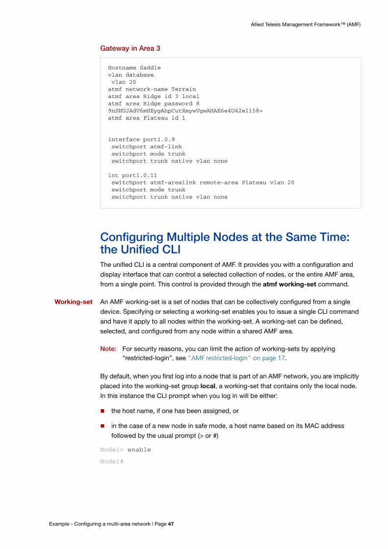
Allied Telesis Management Framework™ (AMF)
Gateway in Area 3
Configuring Multiple Nodes at the Same Time: the Unified CLIThe unified CLI is a central component of AMF. It provides you with a configuration and
display interface that can control a selected collection of nodes, or the entire AMF area,
from a single point. This control is provided through the atmf working-set command.
Working-set An AMF working-set is a set of nodes that can be collectively configured from a single
device. Specifying or selecting a working-set enables you to issue a single CLI command
and have it apply to all nodes within the working-set. A working-set can be defined,
selected, and configured from any node within a shared AMF area.
Note: For security reasons, you can limit the action of working-sets by applying “restricted-login”, see "AMF restricted-login" on page 17.
By default, when you first log into a node that is part of an AMF network, you are implicitly
placed into the working-set group local, a working-set that contains only the local node.
In this instance the CLI prompt when you log in will be either:
the host name, if one has been assigned, or
in the case of a new node in safe mode, a host name based on its MAC address
followed by the usual prompt (> or #)
Node1> enable
Node1#
Hostname Saddlevlan database vlan 20atmf network-name Terrainatmf area Ridge id 3 localatmf area Ridge password 8 9nSHUJAdV6mHEygAhpCutXmywVgwAHAE6e4U42e1158=atmf area Plateau id 1
interface port1.0.9 switchport atmf-link switchport mode trunk switchport trunk native vlan none
int port1.0.11 switchport atmf-arealink remote-area Plateau vlan 20 switchport mode trunk switchport trunk native vlan none
Example - Configuring a multi-area network | Page 47

Allied Telesis Management Framework™ (AMF)
To create a working-set use the command atmf working-set followed by a comma
separated list of the nodes you want to comprise the working-set.
Whenever you select a working-set containing any nodes other than the local device, the
CLI prompt will display the AMF network name—as set by the atmf network-name
command— followed, in square brackets, by the number of nodes contained in the
working-set, such as atmf1[2] as shown in the following example:
Node1# atmf working-set Node1,Node2
Node1,Node2
Working set join
atmf1[2]#
Once you have joined the working-set, any command that you type in will be sent to all
the members of the working-set.
To return to just controlling the local device from any other working-set, use the
command: atmf working-set group local.
Working-set groups
AMF includes the ability to have working-set groups, so that it is not always necessary to
use a comma separated list to specify a working-set.
AMF working-set groups can be split into two types:
automatic
user-defined
Automatic working-set groups
There are three automatic working-set groups that will exist on every AMF network:
1. All—all nodes within the AMF area.
2. Current—the current working-set of nodes. This group is useful for adding additional nodes to the current working-set.
3. Local—the local device.
In any AMF area there will also be a number of other automatic working-set groups that
are dependent on the platform types which exist within the area.
Page 48 | Working-set groups

Allied Telesis Management Framework™ (AMF)
To see the platform- dependent automatic working-set groups that exist within the AMF
area, use the command show atmf group with the automatic parameter:
Output 10: show atmf group members automatic
To select a working-set group use the atmf working-set command with the group
parameter, followed by the group name. You can specify a single group, a comma-
separated list of groups, or a comma-separated list of individual nodes followed by a
comma-separated list of groups. For example, to create a working set made up of
x510_1, x510_2 and all nodes in the group named x900, use the following command:
x908_VCS_1# atmf working-set x510_1,x510_2 group x900
x510_1, x510_2, x908_VCS_1, x908_VCS_2
Working set join
atmf1[4]#
If you specify a partially invalid working-set node list or group list, only the valid nodes
or groups will join the working-set.
If you specify a completely invalid working-set, you will create a working-set containing
no nodes. The switch will generate a warning message to alert you that the current
working-set is empty:
atmf1[3]# atmf working-set group x511
% Warning – working set is now empty
atmf1[0]#
x908_VCS_1#show atmf group members automatic
Retrieving Automatic groups from:x510_1 Master x908_VCS_2 x908_VCS_1
ATMF Group membership
Automatic TotalGroups Members Memberspoe 1 Masterx510 1 x510_1SBx8100 1 Masterx900 2 x908_VCS_2 x908_VCS_1
Working-set groups | Page 49

Allied Telesis Management Framework™ (AMF)
User-defined working-set groups
In addition to the automatic working-set groups, you can create user-defined groups for
arbitrary sets of nodes that you wish to group together, for example, all AMF master
nodes.
To create a user-defined working-set group:
1. Create a working-set containing the desired nodes.
2. Having joined the working-set, then in global configuration mode use the command atmf group.
Master# atmf working-set Master1,Master2
Master1,Master2
Working set join
atmf1[2]# conf t
atmf1[2]# atmf group new-group-name
You can see all user-defined working-set groups that exist on the AMF area with the
command show atmf group members user-defined:
Output 11: show atmf group members user-defined
x908_VCS_1#show atmf group members user-defined
Retrieving Automatic groups from:x510_1 Master1, Master2, x908_VCS_2 x908_VCS_1
ATMF Group membership
User-defined TotalGroups Members Members----------------------------------------------------------------Masters 2 Master1 Master2
Master#
Page 50 | Working-set groups

Allied Telesis Management Framework™ (AMF)
Executing commands on working-sets
Executing commands on a working-set of nodes is very similar to executing commands
on a single AlliedWare Plus device.
When a command is executed that is valid for all nodes within the working-set, the output
is displayed for each of the nodes separately. However, output will be grouped when it is
the same for more than one node.
Here is an example output of the show arp command run from a working-set:
Output 12: show arp command output
atmf1[4]#show arp=======Master:=======
IP Address MAC Address Interface Port Type 172.31.0.1 eccd.6d7d.a542 ATMF sa1 dynamic 172.31.0.3 0000.cd2b.0329 ATMF sa1 dynamic 172.31.0.10 0000.cd37.0163 ATMF sa1 dynamic
=======x510_1:=======
IP Address MAC Address Interface Port Type 172.31.0.2 eccd.6d03.10f9 ATMF sa4 dynamic
===========x908_VCS_1:===========
IP Address MAC Address Interface Port Type 172.31.0.2 0000.cd37.1050 ATMF sa1 dynamic
===========x908_VCS_2:===========
IP Address MAC Address Interface Port Type 172.31.0.2 0000.cd37.1050 ATMF sa3 dynamic
atmf1[4]#
Executing commands on working-sets | Page 51

Allied Telesis Management Framework™ (AMF)
Invalid working-set commands
Some commands can only be executed on particular nodes within the working-set.
Initially the command will be attempted on all nodes within the working-set. However, on
any node for which the command is invalid, the command execution will fail and the
output displayed will indicate the nodes on which the command succeeded and nodes on
which the command failed.
In the example below, output is displayed from the show card command run from a
working-set that is only a valid command for the SBx8100 series switches.
Output 13: SBx8100 series show card command output
Sub-configuration limitations for some nodes in a working-set
There will be some instances where a sub-configuration mode is only valid for some of the
nodes in the working-set. One example of this would be when entering interface
configuration mode for a port that exists on some members of the working-set and not on
others.
For example:
atmf1[4]# conf t
atmf1[4](config)# int port1.1.1
% Can't find interface port1.1.1
atmf1[4:2](config-if)# conf t
In the example above the interface port1.1.1 exists on two of the nodes in the working-
set, but does not exist on nodes “Master” or “x510_1”. The interface configuration mode
fails for these nodes, and a warning message is output to indicate this.
atmf1[4]# show card=======Master:=======
Slot Card Type State-----------------------------------------------1 AT-SBx81GP24 Online2 AT-SBx81GP24 Online3 AT-SBx81GP24 Online4 AT-SBx81XS6 Online5 AT-SBx81CFC400 Online (Active)6 - -7 - -8 - -9 - -10 - -11 - -12 - ------------------------------------------------===============================x510_1, x908_VCS_1, x908_VCS_2:===============================% Invalid input detected at '^' marker.
Page 52 | Executing commands on working-sets

Allied Telesis Management Framework™ (AMF)
Inside the square brackets, the first number indicates the total number of nodes in the
working-set, and the second number indicates the number of nodes in the sub-
configuration mode that has been entered. Any configuration commands configured in
this mode will only be executed on the nodes that successfully entered the sub-
configuration mode.
Entering exit while in this mode will return to global configuration mode for all nodes
within the working-set:
atmf1[4:2](config-if)# exit
atmf1[4](config)# (config)#
Interactive commands
It is inappropriate to execute interactive commands simultaneously across multiple
nodes within a working-set. These commands can only be executed on the local node
working-set or on a working-set with a single member.
When any interactive commands are entered from within a working-set they will give an
error:
atmf1[4]# ping 4.2.2.1
% Working set must contain only single node for this command
The list of current interactive commands, including any optional parameters, are:
ping
mtrace/mstat
traceroute
boot system
boot configuration-file
banner login
tcpdump
edit
copy
move
terminal monitor
Interactive commands | Page 53

Allied Telesis Management Framework™ (AMF)
AMF BackupsAMF backups are a valuable part of AMF network operation. Backups ensure that
appropriate devices within the AMF network have copies of other devices' information
and files. This means that if a node fails, the AMF network can automatically configure its
replacement.
Backups can be performed by either a master, controller, or member node. The
operational details of backups differs between the three types of nodes:
Backups by master nodes
The backups performed by master nodes are a fundamental part of their contribution to
the operation of an AMF area.
They are the mechanism by which AMF master nodes update their records of their AMF
area, and so have all the information and files required to enable automatic node recovery.
By default, AMF master nodes are configured to perform automatically scheduled
backups of the entire AMF area once per day at 3:00 a.m. AMF masters can store their
backups either on remote file servers or on removable media such as USB sticks or SD
cards. These backup files can be used in the recovery of a failed node.
Backups by controller nodes
By default, controller nodes do not perform backups. However, they can be configured to:
backup the master nodes of all their controlled areas, on a regular scheduled basis.
backup a specified set of areas' master nodes immediately.
Controller nodes backup only the master nodes in their controlled areas. They do not
backup member nodes.
Backups by member nodes
The act of a member node performing backups of another member node is required in
order to deal with a specific circumstance - namely when a portion of an AMF network is
located at the end of a virtual-link.
The automatic recovery of a unit that terminates a virtual-link, and accesses its master via
that virtual-link, is less straightforward than the recovery of a unit that has a direct AMF
uplink to its higher-domain neighbor.
If a device has a direct AMF uplink to its higher-domain neighbor and needs to be
replaced; all the replacing device needs to do is send AMF messages from its uplink port
to its neighbor. Its neighbor responds with information about the device being replaced.
The replacing device then requests the master to provide it with the files necessary to fully
adopt the role of the replaced device.
Page 54 | Backups by master nodes

Allied Telesis Management Framework™ (AMF)
However, if a unit is at the end of a virtual-link, there will be one or more non-AMF devices
between itself and the other end of the virtual-link. So, if it sends out AMF messages
towards the master, they will simply be dropped by the non-AMF devices in between.
Figure 10: Backups by member nodes
An alternative solution is required to enable recovery in this situation. The solution is to
enable the member node neighbors of the virtual-link endpoint node to perform limited
backups of the virtual-link endpoint node.
The node at the end of the virtual-link pushes its startup configuration to its adjacent
neighbors. At the time of recovery, the replacement unit then fetches the startup
configuration back and applies the configuration. This provides it with the configuration
required to establish the virtual-link, and thereby make contact with the master node, to
obtain the rest of the files it needs to complete a full recovery.
The AMF messages that the adjacent nodes send to the replacement node indicate that
the sending node has the configuration file that the replacement node needs.
If a recovering node detects a neighbor that indicates it has the required configuration file,
it can then download the configuration file from that neighbor, and apply its configuration.
This restores the recovering node to its prefailure configuration.
MasterSBx8100
Zone containingnon-AMF devices
Member Node
Member Node
AMF packets sent to non-AMF devices will be dropped, as those devices do not know what to do with those packets. So, the replacement node cannot communicate with the Master.
Replacement Node
Far end of
virtual link
Backups by member nodes | Page 55

Allied Telesis Management Framework™ (AMF)
With the original configuration restored the AMF virtual-link becomes operational and the
recovering node can now connect to the area master.
Figure 11: Recovery step 1
Figure 12: Recovery step 2
Figure 13: Recovery step 3
The recovering node then reboots and comes up again running the configuration that
includes the definition of the virtual-link. It re-establishes the virtual-link, and
communicates with the master to complete the recovery.
I have your configuration file
Replacement Node
I have your configuration file
Member Node
Member Node
I would like to download that
configuration filefrom you
Member Node
Member Node
Replacement Node
Replacement Node
Here is the file
Member Node
Member Node
Page 56 | Backups by member nodes

Allied Telesis Management Framework™ (AMF)
Figure 14: Re-establishing the virtual-link
Events that trigger the pushing of the configuration file to neighbor nodes
On appropriate occasions, the node at the end of the virtual-link needs to push its
configuration file to its neighbors.
These appropriate occasions include when:
the running configuration on the node is saved to startup configuration.
the node detects that a new AMF neighbor has been directly connected to it.
the virtual-link on the node goes to the "FULL" state.
a gateway node connected to the virtual-link changes state from non-master to master.
It is important to note that the node terminating the virtual-link does not push its
configuration file to its directly connected neighbors at regular scheduled intervals, but
only when one of the above events occurs. Therefore, if you want to ensure that the
configuration file of the endpoint of a virtual-link has been backed up to its neighbors,
then you should simply copy the running config to startup config. This will also force the
backup to the neighbors to occur.
Zone containingnon-AMF devices
ccoonnttMMFF dd
MasterSBx8100
Member Node
Member Node
Communication with Master, to complete recovery.
Replacement Node
Far end of
virtual link
Virtual link
Backups by member nodes | Page 57

Allied Telesis Management Framework™ (AMF)
Controlling the backup behaviour of controller and master nodes
By default, master nodes will perform a backup of their whole area every day at 3:00 a.m.
The default behavior for controller nodes is not to perform any backups at all.
On master nodes, the performing of backups can be turned on and off with the command:
(no) atmf backup enable
Once backups have been enabled, you can trigger an immediate backup and/or schedule
regular backups, as described in the next section.
On controller nodes, backups can be either enabled or disabled by using the command:
(no) atmf backup area-masters enable
Scheduling backups
Scheduling backups, on both controllers and masters, can be configured with the
command:
atmf backup {default|<hh:mm> frequency <1-24>}
For example, to schedule three backups per day, with the first backup at 7:20 a.m., the
command is:
atmf backup 07:20 frequency 3
Triggering immediate backups
On a master node, the backup of all nodes in its area, or a specified node, can be kicked
off immediately with the command:
atmf backup now [<nodename>]
On a controller, the backup of the masters in all of its controlled areas, or all or one of the
masters in a particular area, can be kicked off immediately with the command:
atmf backup area-masters now [area <area-name>|area <area-name> node <node-name>]
Stopping a backup
To stop a backup that is currently in progress, use the command:
atmf backup stop
Deleting backed up files
On a controller, you can delete the backup files for a given master with the command:
atmf backup area-masters delete area <area-name> node <node-name>
On a master, you can delete the backup files for a given node with the command:
atmf backup delete <node-name>
Page 58 | Controlling the backup behaviour of controller and master nodes

Allied Telesis Management Framework™ (AMF)
Which files are backed up?
The full backup process (i.e. the backup performed by a master or controller node) backs
up most of the files on a node, including its configuration, AlliedWare Plus images, license
files, and more.
The sorts of files that are not backed up are:
stacking configuration
coredump, exception log, tech support etc.
DHCP Snooping database
history and file editor state
random number seed
signature files for security services, because they go out of date— on start-up the
NGFW will check for, and if necessary, download the latest file-set
Backup destinations
Controller and master nodes can save backups to locally installed removal media and/or
to remote file servers.
The backups can be saved to whichever type of removable media that the controller or
master supports - USB or SD card.
When backing up to remote file servers, up to two servers can be specified as backup
destinations for any given master or controller node.
A good level of resilience can be provided by sending backups to both removable media
and remote file servers at the same time as enabled by the command atmf backup
redundancy.
When a master or controller is utilizing more than one backup destination at once (either
two remote file servers or remote file servers and removable media) there are extra rules
and commands that relate to this multi-destination mode of operation.
Note: If multiple AMF Areas are configured to use the same backup server, with the same path a conflict could arise. For example, If there is a device called Router1 in both Areas 1 and 2, the backups will both go to the same directory called .../nodes/Router1 and overwrite each other. To avoid this conflict, it is recommended that you configure different paths for different AMF Areas.
These are discussed below in the section "Multiple backup destinations" on page 71.
Backup destinations | Page 59

Allied Telesis Management Framework™ (AMF)
If an AMF master is storing backup data on removable media then:
If the AMF master is a SBx8100 system with dual CFC controllers, both CFCs should
have removable media installed.
If the AMF master is a VCStack, all stack members should have removable media
installed.
the removable media installed must have sufficient capacity to hold all of the relevant
files stored in the Flash on every node in the AMF area. Typically a 4 GB capacity
removable media storage would be of sufficient size to hold backups for a 40 node
AMF area.
The AMF node backup system has been designed such that the removable media used to
store the backup data can still be used to store other data. However, care needs to be
taken to ensure that enough space is reserved for future AMF backups.
AMF requires up to 128 MB backup space for SBx8100 nodes and up to 64 MB backup
space for other nodes. The output from the show atmf backup command will provide
warnings if free space on the backup media falls below a safe level.
Output 14: Output showing backup media space warning
Safe removal of removable storage media
Removing removable storage media, or rebooting the controller or master node, while an
AMF backup is underway could potentially cause corruption to files in the backup.
Although files damaged as a result of mishandling backup media will be replaced during
the next backup cycle, if the file system on the media becomes damaged, it may require
reformatting before being usable again. To avoid any damage to the AMF backup files or
file system, we recommend that the following procedure be followed before rebooting or
removing any removable storage media from an AMF master or controller:
1. Disable backups to prevent a scheduled backup from occurring while the card is being removed.
2. Terminate any backup already in process.
3. Verify that it is safe to remove the media by checking that backups are disabled and that there are no backups currently in progress.
master1#show atmf backup
Scheduled Backup ...... Disabled Schedule ............ 1 per day starting at 12:45 Next Backup Time .... 25 May 2014 12:45Backup Media .......... SD (Total 3827.0MB, Free 7.1MB) WARNING: Space on backup media is below 64MBCurrent Action ........ Idle Started ............. - Current Node ........ -
Page 60 | Backup destinations

Allied Telesis Management Framework™ (AMF)
Output 15: Example of the safe storage media removal procedure
Once the media has been reinstalled, ensure that the backup scheduler is re-enabled.
Performing a manual backup
Whenever a new device is physically added to the AMF network as a provisioned node,
we recommend that you perform a manual backup from the AMF master.
To perform a manual backup of the entire AMF area, on the AMF master enter the
command atmf backup now:
master1# atmf backup now
master1(config)# atmf backup enable
master1(config)# exit
To check the status of the AMF backup, use the show atmf backup command.
Output 16: Example output from the show atmf backup command entered during a backup
master1#conf t
master1(config)#no atmf backup enablemaster1(config)#exitmaster1#atmf backup stopmaster1#show atmf backup
Scheduled Backup ...... Disabled Schedule ............ 1 per day starting at 12:45 Next Backup Time .... 25 May 2014 12:45Backup Media .......... SD (Total 3827.0MB, Free 3257.1MB)Current Action ........ Idle Started ............. - Current Node ........ -
AMF_Master#show atmf backupScheduled Backup ...... Enabled Schedule ............ 1 per day starting at 03:00 Next Backup Time .... 14 Dec 2013 03:00Backup Media .......... USB (Total 3692.6MB, Free 1782.7MB)Current Action ........ Doing manual backup Started ............. 13 Dec 2012 05:20 Current Node ........ Member1Node Name Date Time In ATMF On Media Status---------------------------------------------------------------------AMF_Master 13 Dec 2012 05:20:16 Yes Yes GoodMember1 - - Yes Yes -Member2 - - Yes No -Member3 - - Yes No -Member4 - - Yes No -
Performing a manual backup | Page 61

Allied Telesis Management Framework™ (AMF)
Below is example output from the show atmf backup command entered after the backup
has completed.
Output 17: Example output from the show atmf backup command entered after backup was completed
Note that the file system used by the AMF backup will not backup files that have the same
name but different case (e.g. “test.txt” and “TEST.txt”), and only one of these files will be
stored in the backup. For this reason we recommend that all files on a node be given
unique file names.
Backups on chassis or VCStacks running as AMF controllers or masters
This section is only applicable in configurations that are not using remote backup servers.
When a chassis is operating as a controller or master node, AMF backups will only occur
on the removable media of the CFC that is the chassis master. Therefore, in the event of a
CFC failure, the new master CFC will have no access to this backup information.
The same applies to the case of a VCStack performing backups. Only the Stack master
will be carrying out backups.
To avoid this situation, you can either configure a remote backup file server or use trigger
scripts to automatically perform a manual backup of the AMF network following a failover
event. This section provides some example trigger scripts to automatically apply a manual
backup. To apply the remote file server solution see "Backing up to remote servers" on
page 65.
Example 1 This example uses a manual backup activation script called triggered-atmfbackup.scp.
When activated, this script applies the following commands to initiate a network backup:
enable
wait 180
atmf backup now
AMF_Master#show atmf backupScheduled Backup ...... Enabled Schedule ............ 1 per day starting at 03:00 Next Backup Time .... 13 Dec 2013 03:00Backup Media .......... USB (Total 3692.6MB, Free 1651.1MB)Current Action ........ Idle Started ............. - Current Node ........ -
Node Name Date Time In ATMF On Media Status---------------------------------------------------------------------ATMF_Master 13 Dec 2013 05:20:16 Yes Yes GoodMember1 13 Dec 2013 05:20:27 Yes Yes GoodMember2 13 Dec 2013 05:20:40 Yes Yes GoodMember3 13 Dec 2013 05:20:52 Yes Yes GoodMember4 13 Dec 2013 05:21:08 Yes Yes Good
Page 62 | Backups on chassis or VCStacks running as AMF controllers or masters

Allied Telesis Management Framework™ (AMF)
When a CFC failure event occurs, the trigger type chassis active-CFC-fail will activate.
The following example shows how the above scripted steps can be automatically applied
if this event occurs.
This example shows a trigger script configuration for the SBx8100:
master1# conf t
master1(config)# trigger 1
master1(config-trigger)# type chassis active-CFC-fail
master1(config-trigger)# script 1 triggered-atmfbackup.scp
To explain the sequence; if there is a failure of a CFC that is operating as a chassis master,
trigger 1, which is associated with the trigger type chassis active-CFC-fail, will activate.This process runs the script triggered-atmfbackup.scp, which will then execute the
command to carry out an atmf backup immediately.
Example 2 In the event of a VCS master failure, the trigger type stack master-fail will activate. The
following example shows how the above scripted steps can be automatically applied if
this event occurs.
This example shows a trigger script configuration that can operate when a stack master
node fails:
Master1# conf t
Master1(config)# trigger 1
Master1(config-trigger)# type stack master-fail
Master1(config-trigger)# script 1 triggered-atmfbackup.scp
To explain the sequence; if there is a failure of a node that is operating as a stack master,
trigger 1, which is associated with the trigger type stack master-fail, will activate.This process runs the script triggered-atmfbackup.scp.
Forcing all master nodes in an area to perform a backup
If there are multiple AMF master nodes in an AMF area, you may also want to use a trigger
script or perform a manual backup by all master nodes after a failover event, so that all
backups are up to date.
Create an AMF working-set group that contains all master nodes in an area, then use the
atmf working-set command in the trigger script to execute the manual backup on all
nodes within the working-set.
To create a working-set containing all AMF master nodes in an area, first manually select
all AMF masters using the atmf working-set command:
Master1# atmf working-set Master1,Master2
NetworkName[2]# conf t
NetworkName[2](config)# trigger 1
Forcing all master nodes in an area to perform a backup | Page 63

Allied Telesis Management Framework™ (AMF)
This command displays an output screen similar to the one shown below:
Enter configuration commands, one per line. End with CNTL/Z
ATMF1{2}# conf t
ATMF1[2](config)# trigger 1
ATMF1[2](config-trigger)# type stack master-fail
ATMF1[2](config-trigger)# script 1 triggered-atmfbackup.scp
Enter configuration commands, one per line. End with CNTL/Z:
ATMF1{2}# conf t
ATMF1[2](config)# trigger 2
ATMF1[2](config-trigger)#type chassis active-CFC-fail
ATMF1[2](config-trigger)#script 1 triggered-atmfbackup.scp
Next, create a user-defined working-set group containing the nodes in the current
working-set using the atmf group (membership) command:
atmf1[2]# conf t
atmf1[2](config) atmf group AMF_masters
You could also carry out a manual backup by all the masters in the area by using the
commands:
atmf working-set group AMF_masters
atmf backup now
=========================================Master1, Master2=========================================
Working set join
ATMF1[2]#
Page 64 | Forcing all master nodes in an area to perform a backup

Allied Telesis Management Framework™ (AMF)
Backing up to remote servers
Because the connection to the remote server(s) must be secure, there are a few steps to
setting up the Remote Server backup.
Setting up SSH keys with the file server
To enable AMF Remote backup, SSH keys need to be setup on the file server.
The following points and processes apply:
1. For the File Server
Any modern Linux server can be used.
The server destination file system should support file permissions. Note, that the FAT32
file system is not supported.
Default OpenSSH versions will work without modifying the SSH settings.
An OpenSSH server daemon must be running with its default settings.
The ability to add known SSH keys to a user.
There must be enough hard drive space on the server (at worst: the sum of all Flash
space on all devices in the network).
Users must be given write access to the folder that is the root of the backup folders.
2. For the Public Key
For security reasons, the exchange of user and host keys must be done manually by the
user using existing crypto commands. This can be done either before or after configuring
the remote file server.
A public host key from the remote file server needs to be imported to the AMF backup
node.
A public user key for root from the AMF backup node needs to be installed on the
remote file server.
The process for this is described in the next two sections.
Backing up to remote servers | Page 65

Allied Telesis Management Framework™ (AMF)
Importing a host key from the remote file server
The following process imports an RSA host key from the remote file server with the IP
address of 10.37.165.65.
Output 18: Importing a host key from remote file server
This process implements a trusted relationship between the server and the AMF master. It
is therefore the users’ responsibility to verify that the public key is being imported from the
correct host, and not a substitute host using the same host name or IP address.
x908(config)#crypto key pubkey-chain knownhosts ip 10.37.165.65 rsa
10.37.165.65 ssh-rsa AAAAB3NzaC1yc2EAAAADAQABAAABAQD4LkpjHYXHrFU6/0vS2PTsIkvKh8j0JkIwIMiBHAxJVadED73G6iq4C6LkNB+M7BZOohF/ow0Bhp4Jr8XK0MfM09gfriRHNNQlGsbfPugDKXnJpFMU88Yu3MaSrkGULgtD7B0MXBEw05HPNjo1RCR9KI3Z3GFGM1TJy8T/6xikczyaxbhqfUeqtpMgDMzRhieqIdpl7Umg4fJxhMDSha8af0HrpRpntsw23+h5IUX9Sw+pG9F1zxczncM1BsKQ579iYA0Ek+pWiFlxK2lziO86oIkYrlcsnHmcYKjrO/9GIlSFSAm6v2bBnXMh6wzcpl0A+6TAU4Bp9c7WNq4KlU0xAre you sure you want to add this public key (yes/no)? yesx908(config)#
Caution When you respond to the question:
“Are you sure you want to add this public key (yes/no)?“You must type in the complete word. For example ‘yes’ (not just the letter ‘y’).
Page 66 | Backing up to remote servers

Allied Telesis Management Framework™ (AMF)
Exporting a public user key from the AMF backup node for the remote file server
1. Generate a public key for root on the AlliedWare Plus Switch:
2. Create a file containing the public key:
3. Confirm that the file exists and looks right.
4. At this stage, transfer the key via TFTP or via removable media. There is no special requirement to keep this key secure.
5. Now on the external server, append the public key to your authorized_keys file.
Linux SSH daemon directory permissions
The Linux SSH daemon file and directory permissions need to be correctly configured.
To set the file permissions on the ssh and authorized_keys directories, use the following
commands:
amf-admin@tb165 ~ $ chmod 700 ~/.ssh
amf-admin@tb165 ~ $ chmod 600 ~/.ssh/authorized_keys
x610a(config)#crypto key generate userkey root rsaGenerating user key for root (1024 bits rsa)This may take a while. Please wait...x610a(config)#exitx610a#
x610a#show crypto key userkey root rsa > root-rsa.pub
x610a#show file root-rsa.pubssh-rsa AAAAB3NzaC1yc2EAAAADAQABAAAAgQDFRNJeSqqMmMesU3wF6RM/F2rieTwU5ILWzstlizVFSz1qLPYb5VaRL8s7pMTElP5aAjIs2dS041a/0WseVt1qYSUlw9kJzcyR26yy+bUzt0L5DspQq+uZkpmvKiTE3BQFvw6RospJh+36fT301ywUPfJiRVyigdYfbch9YG6s4Q==
x610a#copy root-rsa.pub tftp://10.37.165.33/Enter destination file name[root-rsa.pub]:Copying...Successful operationx610a#
amf-admin@atmf23:~$ cat /tftpboot/root-rsa.pub >> ~/.ssh/authorized_keys
Backing up to remote servers | Page 67

Allied Telesis Management Framework™ (AMF)
File/user permissions on the remote file server
The default users/groups and permissions bits should be set to ‘user’ in the folder that is
the root of the backup folders. These defaults should be the same for all directories above
the one supplied. The easiest way to achieve this is to log in as the supplied user to the
server, make the directories required, then not to touch the user/group or permissions on
the folders/files created.
Security on the remote file server
The user will need to create a directory on the remote file server to receive the backed-up
files and directories. The user should limit the permissions on this directory so as to keep
these files as secure as possible. Note that the default permissions will allow group
access to this directory:
Typically this will be access for the user only.
Access to backups is now restricted to the user samh.
Configuring the backup server on the AMF controller/master
Once the keys have been exchanged, the AMF controller or master can be configured to
use the server for backups.
The command to carry out this configuration is:
atmf backup server id {1|2} <hostlocation> username <username>
[path <path>|port <1-65535>]
Where:
id just provides a method for referring to the two different servers if two backup servers
have been configured.
hostlocation is the IPv4 or IPv6 address of the server.
amf-admin@atmf23:~$ mkdir network_backupsamf-admin@atmf23:~$ ls -ltotal 56drwxr-xr-x 4 amf-admin 4096 Dec 19 14:33 atmfdrwxr-xr-x 2 amf-admin 4096 May 1 17:04 network_backupsdrwxr-xr-x 17 amf-admin 32768 May 1 10:23 release_tarballsdrwxr-xr-x 17 amf-admin 12288 Apr 29 14:43 scriptsdrwxr-xr-x 4 amf-admin 4096 Apr 30 13:24 temp
amf-admin@atmf23:~$ chmod 700 network_backups/amf-admin@atmf23:~$ ls -ltotal 56drwxr-xr-x 4 samh stdept 4096 Dec 19 14:33 atmfdrwx------ 2 samh stdept 4096 May 1 17:04 network_backupsdrwxr-xr-x 17 samh stdept 32768 May 1 10:23 release_tarballsdrwxr-xr-x 17 samh stdept 12288 Apr 29 14:43 scriptsdrwxr-xr-x 4 samh stdept 4096 Apr 30 13:24 tempamf-admin@atmf23:~$
Page 68 | Backing up to remote servers

Allied Telesis Management Framework™ (AMF)
username is the name that the controller or master will use when it connects to the server
to write or read backups.
path is the directory path to the folder where the server stores the backups. By default,
this is the home directory of the user specified by the username parameter.
port is the TCP port used for connections to the server. By default, port 22 is used.
For the example being worked through here, the command would be:
atmf backup server id 1 10.37.165.65 username samh path /home/samh/network_backups
Each AMF controller or master supports a maximum of two remote file servers. The
remote backup file servers are mounted on the controller or master’s file system using
SSH and appear as folders.
Configuring a backup to a remote server
After you have configured the servers you can check the backup media, location, log
details, and server status using the show atmf backup command. You can also manually
synchronize the contents of an active server and other configured servers if required.
The following steps describe how to set up two backup servers:
1. Use the command atmf backup server for backup server 1.
This command configures a remote file server(s) as the destination for AMF backups.
Configuration of a remote server will switch the backup process to using remote server functionality and disable any further backup to removable media. Use the no variant of this command to remove the destination servers and revert to backing up to removable media.
Note that if no servers are configured, the backup will go to removable media. If no servers are configured and no removable media exists, no backup will occur. As described below in the section "Multiple backup destinations" on page 71, it is actu-ally possible to override the disabling of the backup to removable media when remote servers have been configured, and thereby backup to both removable media and remote file servers.
2. Repeat step (1) for backup server 2.You should now have two file servers configured to backup your network.As described below in the section "Multiple backup destinations" on page 71, it is actually possible to override the disabling of the backup to removable media when remote servers have been configured, and thereby backup to both removable media and remote file servers.
3. Use the command atmf backup now to force a manual backup of your network.
Note: This step is optional. Alternatively you could wait until the next scheduled back occurs.
4. Use the command show atmf backup.
Backing up to remote servers | Page 69

Allied Telesis Management Framework™ (AMF)
If you forced a manual backup, you will probably want to display the location and state of each configured file server. The display from this command also shows diag-nostic results that test connectivity to each server by using the optional server-status parameter.
In the example shown below, output from the show atmf backup command displays the
configuration of two remote backup file servers.
Output 19: Output from the show atmf backup command - configuration of two remote backup file servers
x908#show atmf backup Scheduled Backup ...... Enabled Schedule ............ 24 per day starting at 14:25 Next Backup Time .... 19 May 2014 11:25 Backup Bandwidth ...... Unlimited Backup Media .......... FILE SERVER (Total 503837.5MB, Free 186818.0MB) Server Config ......... Synchronization ..... Synchronized Last Run .......... 19 May 2014 11:09:50 1 .................. Configured (Mounted) Host .............. 10.36.150.54 Username .......... user_1 Path .............. temp/x908_1 Port .............. - * 2 .................. Configured (Mounted, Primary) Host .............. tb165.test.com Username .......... user_2 Path .............. temp/x908_2 Port .............. - Current Action ........ Idle Started ............. - Current Node ........ --------------------------------------------------------------------------------- Node Name Date Time In ATMF On Media Status Synchronization Date Time From Id To Id Status -------------------------------------------------------------------------------- x210a 19 May 2014 11:09:37 Yes Yes Good 19 May 2014 11:09:46 2 1 Good x610a 19 May 2014 11:09:17 Yes Yes Good 19 May 2014 11:09:19 2 1 Good x610b 19 May 2014 11:09:49 Yes Yes Good 19 May 2014 11:09:49 2 1 Good x610c 19 May 2014 11:09:20 Yes Yes Good 19 May 2014 11:09:20 2 1 Good x610d 19 May 2014 11:09:19 Yes Yes Good 19 May 2014 11:09:19 2 1 Good x908 19 May 2014 11:09:49 Yes Yes Good 19 May 2014 11:09:50 2 1 Good x908stk 19 May 2014 11:09:47 Yes Yes Good 19 May 2014 11:09:48 Yes Yes Good
Page 70 | Backing up to remote servers

Allied Telesis Management Framework™ (AMF)
You can use the show atmf backup command with the parameter server-status to
display the results of the diagnostics that test connectivity to each server:
Output 20: show atmf backup command showing diagnostic test results from each server
Multiple backup destinations
For resilience, AMF enables a master or controller node to store backups in multiple
locations. The backups can go to up to two remote file servers, and to removable media
at the same time.
Backing up to two remote file servers
When a master or controller node is configured with two remote file servers, it will store
backups on both file servers. However, one of the file servers will automatically be
assigned the role of primary server. When a backup is performed, the following sequence
of events occurs:
The master or controller backs up required data to the primary remote server.
When the backup is complete, the master or controller synchronizes the backed-up
files from the primary server over to the other (the backup) server.
The identity of the primary server can be seen from the output of the command:
show atmf backup
One of the servers will be labeled Primary, as shown below:
* 2 .................. Configured (Mounted, Primary)
At any time, you can force the servers to synchronize by using the command:
atmf backup synchronize
For example, if the backup server has been off line for a while, and during that time, a
backup has occurred, then the primary server will have more recent versions of the
backed-up files than the backup server. So, when that backup server is brought back on
line, its data can be brought up to date by running this manual synchronization process.
Master1#sh atmf backup server-status Id Last Check State -------------------------------------1 186 s File server ready 2 1 s SSH no route to host
Multiple backup destinations | Page 71

Allied Telesis Management Framework™ (AMF)
Backing up to remote file server(s) and removable media
If a master or controller has been configured with one or two remote file servers for
backups, then the default behavior is no longer to send backups to removable media.
But, if removable media is present in the unit, and you want to send backups to this media
in addition to the remote file server(s), then this functionality can be implemented by using
the command:
atmf backup redundancy enable
When this has been enabled, the rules are:
If remote file servers are configured and accessible, then the primary backup
destination will always be one of the remote file servers.
When a backup to the primary remote server is complete, the backup is first
synchronized to the other remote file server (if a second remote server has been
configured, and is accessible) and then to the removable media.
The remote file server(s)—if available—is always the preferred location for retrieving
backups for a recovery. The removable media will only be used for delivering files for a
recovery if no remote file servers are accessible.
The command atmf backup synchronize will synchronize the backed-up files
between all backup destinations—the remote file server(s) and the removable media.
If the removable media has been absent for a while, and a new item of removable media
is installed into the controller/master node, the backed-up files on the remote file
server(s) will not be automatically synchronized over to the removable media. This
synchronization must be initiated manually, using the command atmf backup
synchronize.
Page 72 | Multiple backup destinations

Allied Telesis Management Framework™ (AMF)
Node RecoveryAutomatic
node recoveryWith AMF, you can replace a failed node with another device and let AMF automatically
load the appropriate configuration, operating system, licenses, and other files onto the
replacement device.
For this to work, the replacement device must have no configuration file. This means it
must be either:
a factory-new device, or
a used device that has been returned to a “clean” state (see "Restoring a node to a
“clean” state" on page 77)
To replace a failed device with a new device that has either a different platform or a
different node name, you need to provision the network to expect the new device. See
"Node Provisioning" on page 99. When a switch boots up, it follows the process shown in
the flowchart of Figure 15 to determine what configuration to use. This flowchart indicates
when automatic node recovery is successful.
Figure 15: How a switch determines which configuration to use
Is the node already configured?
Is the node connected to an AMF network?
Does the AMF network recognize the node?
Can the node successfully download its configuration from the AMF master?
Download the latest backed-up or provisioned configuration and reboot
Run the default configuration
Run that configuration. This may include connecting
to the AMF network
Run the safe mode configuration
The node is now running the desired configuration
YES
YES
YES
YES
NO
NO
NO
NO
Start here
Multiple backup destinations | Page 73

Allied Telesis Management Framework™ (AMF)
How does the recovering node work out which files to download?
A key step in the flowchart above is “Does the AMF network recognize the node?” This
is the step where the power of AMF comes into play.
When a node disappears and a new, clean, node is added in its place, the following
algorithm is used:
1. The neighbors will send AMF messages with the host name of the previously operating node.
2. The new node will query all known masters to find which has the most recent back-up for that host name given by the adjacent neighbors.
3. The new node will restore all the relevant files that relate to the hostname in question, from the master it has chosen.
A simplified representation of the process is as follows:
Figure 16: How a recovering node works out which files to download
MasterSBx8100
NeighbourReally? I am not Box_5, but I am clean. I should
find the files that will make me Box_5.
Clean Node
Hello, you areBox_5
Please send me the files for Box_5
Here are the files for Box_5
12
3
4
Page 74 | Multiple backup destinations

Allied Telesis Management Framework™ (AMF)
Recommended procedure when replacing a device using automatic node recovery
The following procedure is recommended when replacing a device using AMF automatic
node recovery.
1. Ensure that the replacement device is in a ‘clean’ state, see "Restoring a node to a “clean” state" on page 77
2. Power down the device to be replaced.
3. With the replacement device powered down, move the port connections from the broken device to the replacement device, being careful to ensure the ports are connected in exactly the same way as they were connected to the broken device.
4. Power up the replacement device.
Following these recommendations will ensure AMF can successfully auto-recover the
broken device.
A special note on Lags
If the device to be replaced was connected to the AMF network using aggregators, it is
important to follow the procedure above. Failure to do this may result in the AMF network
failing to auto-recover the device. Failure to auto-recover will leave the device in safe
mode. If this happens, the device may be successfully auto-recovered by ensuring all of
the connections are in place then powering the replacement device down, then back up.
This will re-start the auto-recovery process.
Recommended procedure when replacing a device using automatic node recovery | Page 75

Allied Telesis Management Framework™ (AMF)
Points to note about automatic node recovery
Automatic node recovery is not intended to restore multiple nodes simultaneously. If
multiple nodes have failed, you must recover them one at a time.
Do not make any changes to the device's configuration while a node recovery is
underway. A log message will appear on the console or other VTY session indicating when
recovery has finished (whether successfully or with errors). This message can also be
found by viewing the log with the show log command
Figure 17: Example log output showing automatic node recovery
Recovery progress indication
This is a visual feature that uses front-panel LEDs to display the recovery status during
automatic recovery. This feature uses two distinct flash patterns to indicate the following
states:
Note: This feature is not available on NGFW products (AR3050S and AR4050S).
When using this feature during a recovery failure, you can turn off the failure-alert
indication and return the port LEDs to their normal running state. To do this, use the
command atmf recover led-off. You can repeat this process until the recovery failure has
been rectified.
Note that the Findme and ecofriendly LED features cannot be used while AMF recovery
progress indication is active.
23:03:15 awplus ATMF[863]: ATMF network detected23:03:15 awplus ATMF[863]: ATMF safe config applied (forwarding disabled)23:03:25 awplus ATMF[863]: Shutting down all non ATMF ports23:03:26 x510_1 ATMF[863]: Automatic node recovery started23:03:26 x510_1 ATMF[863]: Attempting to recover as x510_123:03:26 x510_1 ATMF[863]: Checking master node availability23:03:32 x510_1 ATMF[863]: Master has joined. 2 members in total.23:03:32 x510_1 ATMF[863]: x908_VCS_2 has joined. 3 members in total.23:03:32 x510_1 ATMF[863]: x908_VCS_1 has joined. 4 members in total.23:03:37 x510_1 ATMFFSR[2950]: Retrieving recovery data from master node Master23:05:18 x510_1 ATMFFSR[2950]: File recovery from master node succeeded. Node will now rebootFlushing file system buffers...Unmounting any remaining filesystems...Restarting system.
RECOVERY STATE LED INDICATION (GREEN)
Recovery in progress Progressive strobing of all port LEDs.
Recovery failure All port LEDs simultaneously flashing on and off.
Page 76 | Points to note about automatic node recovery

Allied Telesis Management Framework™ (AMF)
Restoring a node to a “clean” state
When replacing a failed device, your replacement device should be one of the following
types, in order for AMF automatic node recovery to work:
a factory-new device
a used device that has been returned to a “clean” state
A clean device is one that has had its previous configuration components removed. A
process of cleaning is required when replacing a failed device with one that, although in
working condition, has been used previously and still retains components of its previous
configuration.
If you keep on-site spares, store them with clean configurations and current releases.
When you upgrade your network to a new AlliedWare Plus version, we recommend that
you upgrade your spare devices too.
To clean up a previously used device, use the atmf cleanup command. This command
erases all data from NVS and Flash, apart from the following:
the boot release file (a .rel file) and its release setting file
license files
The device is then rebooted to put it into a clean state. The device can then be used for
automatic node recovery.
Any other user files that remain in Flash will be overwritten during the automatic recovery
process. If there are any files stored in the Flash of the replacement device that need to be
retained, back these files up prior to installing the device into the AMF network.
Caution If the atmf cleanup command is run on a node that is connected to an AMF network, and the AMF master for that network is currently running a backup, there is a small risk that the files for the node being cleaned will be erased from the AMF master backup. For this reason it is recommended that you disconnect the node from the AMF network before the atmf cleanup command is executed.
Restoring a node to a “clean” state | Page 77

Allied Telesis Management Framework™ (AMF)
Manual node recovery
There are certain situations where automatic recovery may fail. Automatic recovery has
been designed to be cautious in its approach to recovering nodes for reasons such as:
the backup stored on the AMF master does not have a “good” status
the replacement device has a version of the AlliedWare Plus operating system installed
on it that too old to be compatible with Alliedware Plus version running on the neighbor
or the master.
When these situations occur, automatic node recovery will fail.
In this failed state, the replacement device will have the AMF safe configuration mode
applied (see "AMF safe configuration procedures" on page 80). After investigating the
failure and taking remedial action, you may choose to initiate a manual node recovery. To
do this, enter the following command:
amf1# atmf recover {<node_name>} {<master_node_name>}
where:
node_name is the host name of the device being recovered.
master_node_name is the host name of the AMF master that contains the backup you
want to use for the recovery.
The manual recovery command will bypass the usual checks performed by automatic
node recovery. Make sure that the backup configuration stored on the specified AMF
master is correct before you execute the command.
If you attempt to manually recover a node with the backup file of a node from a different
platform, the release file from the backup will be incompatible and won’t be copied to the
replacement device. Instead, the existing release on the replacement device will be used,
in order to ensure the device can join the AMF network and function correctly.
Output 21: Example output showing manual recovery
amf1#atmf recover x510_1 MasterThis command will erase ALL flash contents. Continue node recovery? (y/n)yManual node recovery successfully initiatedx510_1#23:15:32 x510_1 ATMFFSR[8477]: Retrieving recovery data from master node Master23:17:17 x510_1 ATMFFSR[8477]: Manual node recovery completedx510_1#
Page 78 | Manual node recovery

Allied Telesis Management Framework™ (AMF)
Node recovery on VCStacks
Node recovery on VCStacks that are part of an AMF network is slightly different to node
recovery of standalone devices.
This is because VCStack has its own node recovery mechanism that has different
requirements to AMF.
In the extremely unlikely situation of needing to replace an entire VCStack within an AMF
network, you can use AMF automatic node recovery to first recover Stack ID 1, which will
become the VCStack master.
The replacement device for this must be a clean unit, (see "Restoring a node to a “clean”
state" on page 77).
The procedure for recovering an entire stack is as follows:
Connect a clean device to the AMF network, and power it on. The connections into the
AMF network should be between the appropriately configured AMF links on the
neighboring node, and the ports configured as AMF links in the backup of the failed
node’s configuration, (i.e. the ports configured as AMF links on the failed node).
The AMF network should detect the replacement device and begin the automatic node
recovery process. Wait until this process completes, then check that the replacement
device has come up correctly as VCStack ID 1, and that the configuration is correct.
Configure the next replacement device as VCStack ID 2. Ensure it is installed with a
compatible release and the same set of licenses that exist on ID 1. Connect the
VCStack cables and power it on.
VCStack ID 1 should detect ID 2 and synchronize the configuration and firmware
release. Once this has completed, check that the VCStack has formed correctly, and
then connect the remaining network connections.
For any additional VCStack members, repeat the last two steps, ensuring that the
VCStack ID is set to the next sequential value for each additional device that is added to
the VCStack.
Node recovery on VCStacks | Page 79

Allied Telesis Management Framework™ (AMF)
Recovery of switches that require release licenses
SwitchBlade x908 and SwitchBlade x8100 switches need to have release licenses
installed. These release licenses are keyed to the MAC address of the device. If an
existing SwitchBlade is removed from the network, and replaced by a new one, the new
unit will not have the same MAC address as the unit that was removed. As a result, the
release license that was backed up from the original unit will not apply to the new unit.
The procedure to deal with this situation is:
1. Even though the new unit will not have a valid release license initially, the lack of relevant release licenses will not block a firmware upgrade via AMF. The software will be successfully installed on the new unit, and it will run in unlicensed mode (which means that it will not be able to upgrade to yet further software versions).
2. Following the successful recovery of a failed device and once the release license(s) for the replacement device has/have been obtained, these can then be installed on the new device using the license command. To obtain release license(s), contact Allied Telesis support.
Note that backed up feature licenses (unless they are tied to a physical entity such as a
device serial number or MAC address) will automatically be installed into the replacement
unit.
AMF Safe configuration
If AMF automatic node recovery fails, AMF contains a safety net feature that puts the
replacement node into a safe configuration state. This is to prevent an unconfigured
device from joining the network and creating loops.
Detecting AMF safe configuration operation
A log message is generated whenever AMF safe configuration is applied. This message
will appear in the log some time after the startup sequence. This message will also be
displayed on the console or any connected VTY session.
AMF safe configuration procedures
The procedures for AMF safe configuration are shown below:
A special VLAN is created in the disabled state and given the name
atmf_node_recovery_safe_vlan. The VID of this VLAN is determined dynamically to
ensure that it does not conflict with either of the AMF management VLANs or any other
VLANs that are detected on the AMF network.
All ports are removed from their default VLAN membership (VLAN 1).
All ports are set as tagged members of the safe VLAN.
Additionally, all ports that are not AMF links or cross-links are shut down. These links
and crosslinks are detected by AMF and added to the dynamic configuration. This is
done to ensure correct behavior of static aggregators and Layer 3 protocols configured
on neighboring devices.
Page 80 | Recovery of switches that require release licenses

Allied Telesis Management Framework™ (AMF)
Output 22: show vlan command output - the brief parameter set for a device in AMF safe configuration mode
Output 23: show running-config output for a device in AMF safe configuration mode
awplus#show vlan brief
VLAN ID Name Type State Member ports (u)-Untagged, (t)-Tagged======= ================ ======= ======= =======================================1 default STATIC ACTIVE 4090 atmf_node_recovery_safe_vlan STATIC SUSPEND port1.1.1(t) port1.1.2(t) port1.1.3(t) port1.1.4(t) port1.1.5(t) port1.1.6(t) port1.1.7(t) port1.1.8(t) port1.1.9(t) port1.1.10(t) port1.1.11(t) port1.1.12(t) port1.1.13(t) port1.1.14(t) port1.1.15(t) port1.1.16(t) port1.1.17(t) port1.1.18(t) port1.1.19(t) port1.1.20(t) port1.1.21(t) port1.1.22(t) port1.1.23(t) port1.1.24(t)
awplus#show running-config ...!vlan database vlan 4090 name atmf_node_recovery_safe_vlan vlan 4090 state disable!interface port1.0.1-1.0.4 shutdown switchport switchport mode trunk switchport trunk allowed vlan add 4090 switchport trunk native vlan none!interface port1.0.5 switchport switchport atmf-link switchport mode trunk switchport trunk allowed vlan add 4090 switchport trunk native vlan none!interface port1.0.6-1.0.24 shutdown switchport switchport mode trunk switchport trunk allowed vlan add 4090 switchport trunk native vlan none!...
AMF Safe configuration | Page 81

Allied Telesis Management Framework™ (AMF)
Undoing an AMF safe configuration
If your node has had AMF safe configuration applied, you can use normal CLI
configuration commands to modify the running-configuration to whatever configuration is
required.
The example below shows a device being returned from AMF safe configuration mode to
having its default VLAN and port settings applied. Note that in this example a 24-port
interface card has been used.
awplus# configure terminal
awplus(config)# interface port1.0.1-port1.0.24
awplus(config)# interface port1.1.1-port1.1.24
awplus(config-if)# switchport trunk native vlan 1
awplus(config-if)# switchport trunk allowed vlan remove 4090
awplus(config-if)# switchport mode access
% port1.1.5 has ATMF link configured so its mode cannot be changed
% port1.0.5 has ATMF link configured so its mode cannot be changed
awplus(config-if)# no shutdown
awplus(config-if)# exit
awplus(config-if)# vlan database
awplus(config-if)# no vlan 4090
awplus(config-if)# end
In order to retain connectivity to the AMF network, AMF link and crosslink settings should
not be changed. In the example above you can see that port1.0.5 is an automatically
configured AMF link.
Caution No changes should be made to the device's configuration while a node recovery
is underway. A log message will appear on the console or other logged in session
indicating when recovery has finished (whether successfully or with errors). This
message can also be found by viewing the log after running the show log
command.
Page 82 | AMF Safe configuration

Allied Telesis Management Framework™ (AMF)
How to recover a TQ AP Guest
When correctly configured as AMF Guest Nodes, Allied Telesis TQ-series access points
offer the additional advantage that their configuration files can be included in the
automated backups performed by AMF. While zero-touch recovery is not available on
AMF Guest nodes, TQ-series access points included in the AMF backup regime can have
their configuration manually recovered. This is useful when replacing a failed TQ device.
The following example shows the configuration, backup, and restore of a TQ access point
using AMF.
Guest
Member
x310
x610
Office NetworkDHCP server 10.16.36.0/24
subnet
Master
1.0.2
1.0.1
1.0.1
1.0.2
How to recover a TQ AP Guest | Page 83

Allied Telesis Management Framework™ (AMF)
Annotated x610 (AMF Master) configuration!service password-encryption!hostname x610!no banner motd!username manager privilege 15 password 8 $1$bJoVec4D$JwOJGPr7YqoExA0GVasdE0!no service ssh!platform hwfilter-size ipv4-limited-ipv6!service telnet!service http!no clock timezone!snmp-server!aaa authentication enable default localaaa authentication login default local!stack virtual-chassis-id 2132!atmf network-name MyNetatmf masteratmf backup bandwidth 250!ip domain-lookup!no service dhcp-server!no ip multicast-routing!spanning-tree mode rstp!lacp global-passive-mode enable!switch 1 provision x610-48!interface port1.0.1 switchport switchport mode access!interface port1.0.2 switchport switchport atmf-link switchport mode trunk!interface port1.0.3-1.0.50 switchport switchport mode access!interface vlan1 ip address dhcp!line con 0 exec-timeout 0 0line vty 0 4!End
Page 84 | How to recover a TQ AP Guest

Allied Telesis Management Framework™ (AMF)
Annotated x310 configuration!service password-encryption!hostname x310!no banner motd!username manager privilege 15 password 8 $1$bJoVec4D$JwOJGPr7YqoExA0GVasdE0!no service ssh!platform hwfilter-size ipv4-limited-ipv6!service telnet!service http!no clock timezone!snmp-server!aaa authentication enable default localaaa authentication login default local!stack virtual-chassis-id 1865!atmf network-name MyNet!atmf guest-class TQAP (With guest-class, dynamic discovery is the default) modeltype tq username manager password 8 9gzfX8VlZFw5ZKDsepGsKAm7LodYtmhJo5aK3vak7h8=! (A username and password is mandatory when using the ‘tq’ modeltype)ip domain-lookupno service dhcp-server!no ip multicast-routing!service dhcp-snooping (This is important; so we can detect when guests leave)ip dhcp snooping delete-by-linkdown!spanning-tree mode rstp!lacp global-passive-mode enable
!switch 1 provision x310-50!interface port1.0.1 switchport switchport atmf-link
switchport mode trunk ip dhcp snooping trust (This is basic DHCP, it identifies the uplink port that we expect DHCP requests to go to)!interface port1.0.2 switchport switchport atmf-guestlink class TQAP (This is the port that we will connect the guest device to)
switchport mode access!interface port1.0.3-1.0.50
How to recover a TQ AP Guest | Page 85

Allied Telesis Management Framework™ (AMF)
switchport switchport mode access
!interface vlan1 ip dhcp snooping (We want to snoop on this interface for guests) ip address dhcp (The interface on the guest parent interface MUST have an IPv4 address)!line con 0 exec-timeout 0 0line vty 0 4!end
TQ4600 Information
Page 86 | How to recover a TQ AP Guest

Allied Telesis Management Framework™ (AMF)
Some sample show commands
show atmf nodes all
show atmf guests
show atmf guests detail
x610#show atmf nodes all
Node and Guest Information:
* = Local device
SC = Switch Configuration: C = Chassis S = Stackable N = Standalone G = Guest
Node/Guest Device ATMF Parent Node Name Type Master SC Domain Depth---------------------------------------------------------------------* x610 x610-48Ts/X Y S none 0 x310 x310-50FT N S x610 1 x310-1.0.2 AT-TQ4600 N G x310 -
Current ATMF node count 3 (guests 1)
x610#show atmf guests
Guest Information:
Device Device Parent Guest IP/IPv6 Name Type Node Port Address--------------------------------------------------------------------- x310-1.0.2 AT-TQ4600 x310 1.0.2 10.16.36.158
Current ATMF guest node count 1
x610#show atmf guests detail
ATMF Guest Node Information:
Node Name : x310Port Name : port1.0.2Ifindex : 5002Guest Description : x310-1.0.2Device Type : AT-TQ4600Backup Supported : YesMAC Address : eccd.6df3.0f20IP Address : 10.16.36.158IPv6 Address : Not SetHTTP Port : 0Firmware Version : 3.3.0 B02
How to recover a TQ AP Guest | Page 87

Allied Telesis Management Framework™ (AMF)
show atmf backup guests
show atmf links
Structure of the backup media for guest node backups
The following diagram shows the structure of the backup media for guest node backups
with the guest config backup file highlighted:
admin@amf-backup-server:~$ tree /media/sf_server-share/atmf/MyNet/media/sf_server-share/atmf/MyNet├── areas├── guests│ ├── info│ │ └── x310│ ├── logs│ │ └── x310│ ├── nodes│ │ └── x310│ │ └── port1.0.2│ │ └── config.xml├── info├── logs└── nodes ├── x610 │ └── flash └── x310 └── flash
x610#atmf backup guests nowx610#show atmf backup guestsGuest Backup .......... Enabled Schedule ............ 1 per day starting at 03:00 Next Backup Time .... 07 Oct 2016 03:00Backup Bandwidth ...... 250 KBpsBackup Media .......... SD (Total 1875.7MB, Free 1513.2MB)Current Action ........ Idle Started ............. - Current Node ........ -Backup Redundancy ..... Disabled
Parent Node Name Port Name Date Time Status---------------------------------------------------------------------x310 port1.0.2 06 Oct 2016 13:42:12 Good
x310#show atmf links
ATMF Link Brief Information:
Local Link Link ATMF Adjacent Adjacent LinkPort Type Status State Node/Area Ifindex State---------------------------------------------------------------------1.0.1 Uplink Up Full x610 5002 Forwarding1.0.2 Guestlink Up Full x310-1.0.2 - Active
* = Provisioned.
Page 88 | How to recover a TQ AP Guest

Allied Telesis Management Framework™ (AMF)
How to manually recover a failed TQ AP guest.
In this example, we have already replaced the failed device with another TQ-4600.
x310#debug atmf errorx310#terminal monitorx310#atmf recover guest port1.0.2 (This command only takes a few seconds to complete. Note that it must be run on the guest parent node. If the restore succeeds the AP will be restarted automatically.)15:07:12 x310 IMISH[6105]: [manager@ttyS0]atmf recover guest port1.0.215:07:12 x310 ATMFFSR[22152]: Attempting to ping master (x610) (attempt=1)15:07:13 x310 ATMFFSR[22152]: Automatic node recovery ping -c 1 -w 1 172.31.1.12 was successful15:07:13 x310 ATMFFSR[22152]: Node recovery pinged master (x610) reached15:07:13 x310 ATMFFSR[22152]: Node recovery found 1 potential nodes with recovery services15:07:13 x310 ATMFFSR[22152]: Interrogating node x610 for backup15:07:13 x310 ATMFFSR[22152]: Selected master recovery node x61015:07:13 x310 ATMFFSR[22152]: RSYNC COMMAND: rsync -rtDqhW --modify-window=1 --stats --itemize-changes --timeout=30 --bwlimit=250 --log-file=/var/log/atmf_guest_recovery 172.31.1.12::EXMEDIA/MyNet/guests/nodes/x310/port1.0.2 /tmp/.atmf_guest/recover15:07:18 x310 DHCPSN[15262]: Binding Delete: 10.16.36.158, chaddr eccd.6df3.0f20, vlan1, port1.0.2, Server 10.16.36.254, Type Dynamic (with 691065 seconds remaining)15:07:18 x310 NSM[602]: Port down notification received for port1.0.2
15:07:20 x310 NSM[602]: Port up notification received for port1.0.215:07:42 x310 MSTP[876]: CIST port1.0.2 now forwarding, propagating TC to other ports15:07:44 x310 DHCPSN[15262]: Binding Add: 10.16.36.158, chaddr eccd.6df3.0f20, vlan1, port1.0.2, Server 10.16.36.254, Type Dynamic, Expires in 691200 secondsx310#
Note that the text shown in grey above is only displayed if the terminal monitor is
activated with the command debug atmf error enabled.
How to recover a TQ AP Guest | Page 89

Allied Telesis Management Framework™ (AMF)
Firmware Auto UpgradeThere are two recommended methods for performing a firmware upgrade on an AMF
area:
1. AMF reboot-rolling upgrade
2. AMF distribute firmware upgrade
The reboot-rolling firmware upgrade feature allows nodes within an AMF area to be
rebooted and upgraded in a rolling sequence in order to minimize downtime and reduce
the management overhead. The distribute firmware upgrade feature enables nodes within
an AMF area to be upgraded and then rebooted at a later time.
Note: The atmf reboot-rolling command can also be used to reboot a set of nodes without upgrading the firmware. Specifying the force parameter on the atmf reboot-rolling command will result in the upgrade continuing even if an upgrade or reboot fails for a particular node.
AMF reboot-rolling feature is supported from firmware version 5.4.3 and the AMF
distribute firmware feature is supported from firmware version 5.4.4. Reboot-rolling and
distribute firmware upgrades are not supported on the GS900MX series switches.
Advantages of reboot-rolling upgrade
The reboot-rolling upgrade offers the following advantages:
A fully automated upgrade process with report on completion (assuming the initiating
node is excluded from the rolling reboot upgrade process).
The AMF reboot-rolling algorithm automatically selects the appropriate order in which
to upgrade the nodes (edge to core).
The most up-to-date appropriate release is automatically selected from the specified
location for each platform (removable media only).
Multiple nodes can be upgraded and rebooted with a single command.
AMF checks that each node completes the upgrade successfully and that the node re-
joins the network before proceeding to upgrade the next node.
During the upgrade AMF provides rolling updates for the number of nodes that have
been upgraded and rebooted, and the total elapsed time since the upgrade was
initiated.
A report is generated at the end of the reboot-rolling upgrade. (If the initiating node is
excluded from the reboot-rolling upgrade working-set).
Page 90 | Advantages of reboot-rolling upgrade

Allied Telesis Management Framework™ (AMF)
Disadvantages of reboot-rolling upgrade
The reboot-rolling upgrade does however suffer from the following disadvantages:
The upgrade operation is not separated from the reboot operation.
Since only one node is upgraded and rebooted at a time it could take a long time to
upgrade a large network.
Advantages of distribute firmware upgrade
The most up-to-date appropriate release is automatically selected from the specified
location for each platform.
The upgrade operation is separate from the reboot operation, so a working-set of
nodes can be loaded with new firmware, but rebooted at a later convenient time.
Once the new firmware is distributed to a working-set of nodes, the nodes can be
manually rebooted individually, in groups, or all at the same time.
Support for AMF Network UpgradesAs a general rule, Allied Telesis will support upgrading an AMF network spanning up to
two major releases (e.g. From 5.4.4-0.x to 5.4.6-0.x) including all intervening maintenance
releases. (e.g. From 5.4.4-0.4 to 5.4.6-0.3). For AMF network upgrades that span more
than two major releases, it may be necessary to upgrade the network in two stages. (e.g.
from 5.4.4-0.x to 5.4.6-0.x, and then from 5.4.6-0.x to 5.4.7-0.x).
Note: Allied Telesis strongly recommends that all nodes in an AMF network run the same firmware version, and that running different versions should be limited to the periods between staged upgrades of the network. Where the network contains End of Life devices these should run the latest available maintenance release.
AMF upgrade exceptions
There are a few exceptions to the general rule stated above due to known
incompatibilities that exist between particular firmware releases. Refer to the table below
for details:
Note: The following procedure offers a method of avoiding these upgrade restrictions. Use the AMF distribute firmware command to upgrade all nodes in an area and then apply a working-set to simultaneously reboot all AMF nodes in that area. Upgrading the network using this method means at no time are nodes having to interoperate across different firmware versions.
ALLIEDWARE PLUS RELEASE AFFECTED PLATFORMS COMPATIBLE WITH
5.4.3-0.1 - 5.4.3-2.5 All 5.4.3 only
5.4.3-2.6 onwards All 5.4.4-0.1 and above
5.4.4-0.x x210 5.4.4-1.2 and above
Disadvantages of reboot-rolling upgrade | Page 91

Allied Telesis Management Framework™ (AMF)
Summary of the AMF upgrade process
There are a number of steps to follow in order to upgrade nodes within an area using AMF.
These steps are summarized below:
1. Select a group of nodes to be upgraded.
2. Select the new release for each platform to be upgraded in the AMF area.
3. Copy the releases to the location you intend to use for the upgrade.
4. Decide which AMF upgrade method is most suitable for your network.
5. Check that each node to be upgraded (including all members of VCStacks) has enough space in Flash to hold the new release, and is set to boot from Flash.
6. Initiate the AMF network upgrade using your selected method. The AMF upgrade can be initiated from any node in the AMF area. It does not have to be initiated from the master.
Detailed explanation of the AMF upgrade process
This section expands on the steps listed above:
1. Select a group of nodes that need to be upgraded.
While we recommend that all nodes in an AMF network are eventually upgraded to the
same release, you may decide to perform the upgrade on a selected nodes first. If you
elect to use the AMF reboot-rolling upgrade method you may also wish to exclude the
node that is controlling the upgrade in order for it to generate a report once the upgrade
has completed.
2. Select the new release for each platform to be upgraded in the AMF area.
Once you have decided to upgrade your AMF network, you need to look at which product
families your network contains and select an appropriate release for each platform. We
strongly recommend that the same firmware version is applied to each platform where
possible.
3. Copy the releases to the location you intend to use for the upgrade.
The supported media locations for AMF network upgrades are:
Flash
Removable SD card
Removable USB storage
TFTP server
SCP server
HTTP server
Page 92 | Summary of the AMF upgrade process

Allied Telesis Management Framework™ (AMF)
If you specify either Flash or removable storage media, the newest compatible release for
each node will be selected from the stored releases.
Note: Removable storage media must not contain more than 20 releases. More than this and the upgrade will fail and an error message will be generated. If the release file is to be copied from a remote storage location (e.g. via TFTP, HTTP, etc.), then the URL should specify the exact release file-name without using wild card characters. If you are using removable storage media to store the new firmware releases, this must be installed in the node used to initiate the upgrade. If you are using a remote server as the source location for the new firmware releases, the server must be reachable from the node used to initiate the upgrade. The AMF upgrade can be initiated from any node in the AMF network.
4. Decide which AMF upgrade method is most suitable for your network.
The AMF upgrade method that is most suitable for your network will depend on your
network topology and your individual requirements. If you prefer an upgrade method that
reboots each node one at a time (so that the outage is limited to only what is connected to
that node), and then checks that the node successfully re-joins the network before
proceeding to upgrade and reboot the next node, then the AMF reboot-rolling method
may suit your network. If your network demands a shorter period of interruptions, then it
may be more appropriate to use the AMF distribute firmware method so that all nodes can
rebooted at the same time.
5. Check that each node to be upgraded, including all members of VCStacks, has enough space in Flash to hold the new release and is configured to boot from Flash.
Once you have decided which AMF upgrade method is most appropriate for your
network, the simplest way to determine whether the nodes to be upgraded have enough
space in Flash to hold the new firmware version is to create a working-set of the nodes to
be upgraded and use the chosen AMF upgrade command on the working-set. This will be
either atmf reboot-rolling location or atmf distribute firmware location, where location
is one of the supported media locations.
Note: If a remote storage location (e.g. via TFTP, HTTP, etc.), is specified, then this step must be performed separately for each product family, as the exact release file name without using wild card characters must be entered.
These commands will perform several checks on the working-set of nodes to ensure that
the upgrade will succeed, including checking that each node is set to boot from Flash,
and that they have enough free space, before prompting you to confirm whether you wish
to proceed with the upgrade.
Detailed explanation of the AMF upgrade process | Page 93

Allied Telesis Management Framework™ (AMF)
Output 24: amf upgrade showing node with insufficient space
If the AMF upgrade command indicates that there are nodes with insufficient space you
can cancel the upgrade operation and free up the necessary space in Flash on those
nodes.
6. Initiate the AMF network upgrade using the selected method.
Once you have confirmed that all nodes to be upgraded have enough free space in Flash,
you can then initiate the AMF upgrade using the chosen upgrade command. Each node
will be updated to boot from the new release and the previous release will be set as the
backup release file.
Note: If the AMF distribute firmware method is being used, then the nodes must be rebooted manually to complete the upgrade.
core1#atmf working-set group all=====================================================================core1, core2, distribution1, distribution2, edge1, edge2: =====================================================================
Working set join
AMFname[6]#atmf distribute firmware usb:Retrieving data from core1Retrieving data from core2Retrieving data from distribution1Retrieving data from distribution2Retrieving data from edge1Retrieving data from edge2
ATMF Firmware Upgrade:
Node Name New Release File Status ---------------------------------------------------------------------core1 SBx81CFC400-5.4.4-0.6.rel Release ready core2 SBx81CFC400-5.4.4-0.6.rel Release ready distribution1 x610-5.4.4-0.6.rel Release ready distribution2 x610-5.4.4-0.6.rel Release ready edge1 x510-5.4.4-0.6.rel Insufficient space edge2 x510-5.4.4-0.6.rel Release ready
Continue upgrading releases ? (y/n):
Page 94 | Detailed explanation of the AMF upgrade process

Allied Telesis Management Framework™ (AMF)
Example 1 - Performing a reboot-rolling upgrade
To perform a reboot-rolling firmware upgrade on all nodes in the AMF area, first select all
nodes using the default working-set group all command:
Next, using the atmf reboot-rolling command specify the path to the release files to
which you wish to upgrade the nodes in the AMF network. In this example, the release
files are stored on the removable USB storage media installed in the node controlling the
reboot-rolling firmware upgrade, in a directory called “rel”. Note that because the node
controlling the reboot-rolling firmware upgrade is included in the nodes to be upgraded, a
message is displayed indicating that no summary will be available on completion.
Although no summary report was generated in this particular example, you can refer to
the progress messages output to the console to confirm that the upgrades were
successful. You can also use the atmf working-set group all and the show boot
commands to confirm the current boot image for each node in the AMF area.
SBx8100#atmf working-set group all==================================================SBx8100, SBx908-VCS1, SBx908-VCS2, x510_1, x510_2:==================================================Working set join
csg_vcf[5]#atmf reboot-rolling usb:/rel/*.relRetrieving data from SBx8100Retrieving data from SBx908-VCS2Retrieving data from x510_1Retrieving data from x510_2Retrieving data from SBx908-VCS1
ATMF Rolling Reboot Nodes:
TimeoutNode Name (Minutes) New Release File Status---------------------------------------------------------------------x510_2 9 x510-main-20121203-1.rel Release readyx510_1 6 x510-main-20121203-1.rel Release readySBx908-VCS1 9 x900-main-20121203-1.rel Release readySBx908-VCS2 9 x900-main-20121203-1.rel Release readySBx8100 11 SBx81CFC400-main-20121203 Release ready -1.rel% The controlling node (SBSBx8100) is included in therolling reboot and will be rebooted last.No summary will be available on completion.Continue upgrading releases ? (y/n):=====================================================================Copying Release : x510-main-20121203-1.rel to x510_2Updating Release : x510-main-20121203-1.rel information on x510_2==================================================================ATMF Rolling Reboot: Rebooting x510_2====================================================================02:11:32 SBx8100 ATMF[1973]: x510_2 has left. 4 members in total.
% x510_2 has left the working-set02:13:30 SBx8100 ATMF[1973]: x510_2 has joined. 5 members in total.Reboot of x510_2 has completed
Example 1 - Performing a reboot-rolling upgrade | Page 95

Allied Telesis Management Framework™ (AMF)
Note: Removable storage media must not contain more than 20 releases or the upgrade will not proceed and an error message will be generated. If the release file is to be copied from a remote storage location (e.g. via TFTP, HTTP, etc.), then the URL should specify the exact release filename without using wild card characters.
=====================================================================Copying Release : x510-main-20121203-1.rel to x510_1Updating Release : x510-main-20121203-1.rel information on x510_1=====================================================================ATMF Rolling Reboot: Rebooting x510_1====================================================================02:14:13 SBx8100 ATMF[1973]: x510_1 has left. 4 members in total.
% x510_1 has left the working-set02:15:53 SBx8100 ATMF[1973]: x510_1 has joined. 5 members in total.Reboot of x510_1 has completed
=================================================Copying Release : x900-main-20121203-1.rel to SBx908-VCS1Updating Release : x900-main-20121203-1.rel information on SBx908-VCS1====================================================================ATMF Rolling Reboot: Rebooting SBx908-VCS1====================================================================02:19:02 SBx8100 ATMF[1973]: x510_1 has left. 4 members in total.02:19:02 SBx8100 ATMF[1973]: SBx908-VCS1 has left. 3 members in total.
% SBx908-VCS1 has left the working-set02:20:48 SBx8100 ATMF[1973]: SBx908-VCS1 has joined. 4 members in total.Reboot of SBx908-VCS1 has completed02:20:51 SBx8100 ATMF[1973]: x510_1 has joined. 5 members in total.=================================================================Copying Release : x900-main-20121203-1.rel to SBx908-VCS2Updating Release : x900-main-20121203-1.rel information on SBx908-VCS2=====================================================================ATMF Rolling Reboot: Rebooting SBx908-VCS2====================================================================02:21:54 SBx8100 ATMF[1973]: x510_2 has left. 4 members in total.02:21:54 SBx8100 ATMF[1973]: SBx908-VCS2 has left. 3 members in total.
% SBx908-VCS2 has left the working-set02:23:35 SBx8100 ATMF[1973]: SBx908-VCS2 has joined. 4 members in total.Reboot of SBx908-VCS2 has completed=====================================================================Copying Release : SBx81CFC400-main-20121203-1.rel to SBSBx810002:23:39 SBx8100 ATMF[1973]: x510_2 has joined. 5 members in total.Updating Release : SBx81CFC400-main-20121203-1.rel information on SBx8100=====================================================================ATMF Rolling Reboot: Rebooting SBSBx8100=====================================================================02:24:07 SBx8100 ATMF: reboot-rolling Rebooting SBx8100 at request of user manager.
Page 96 | Example 1 - Performing a reboot-rolling upgrade

Allied Telesis Management Framework™ (AMF)
Example 2 - AMF distribute firmware upgrade
To perform an AMF distribute firmware upgrade:
1. First select the set of nodes you wish to upgrade using the atmf working-set command:
2. Then, using the atmf distribute firmware command, specify the path to the release files to use for the upgrade. In this example the release files are being stored on the removable USB storage media in the controlling node named Core1, which in this instance is excluded from the upgrade.
Note: As previously mentioned, removable storage media must not contain more than 20 releases or the upgrade will not proceed and an error message will be generated. If the release file is to be copied from a remote storage location (e.g. via TFTP, HTTP, etc.), then the URL should specify the exact release file name without using wild card characters.
atmf working-set core2, group x510,x610=========================================================core2, distribution1, distribution2, edge1, edge2:=========================================================
Working set join
AMFname[5]#
Example 2 - AMF distribute firmware upgrade | Page 97
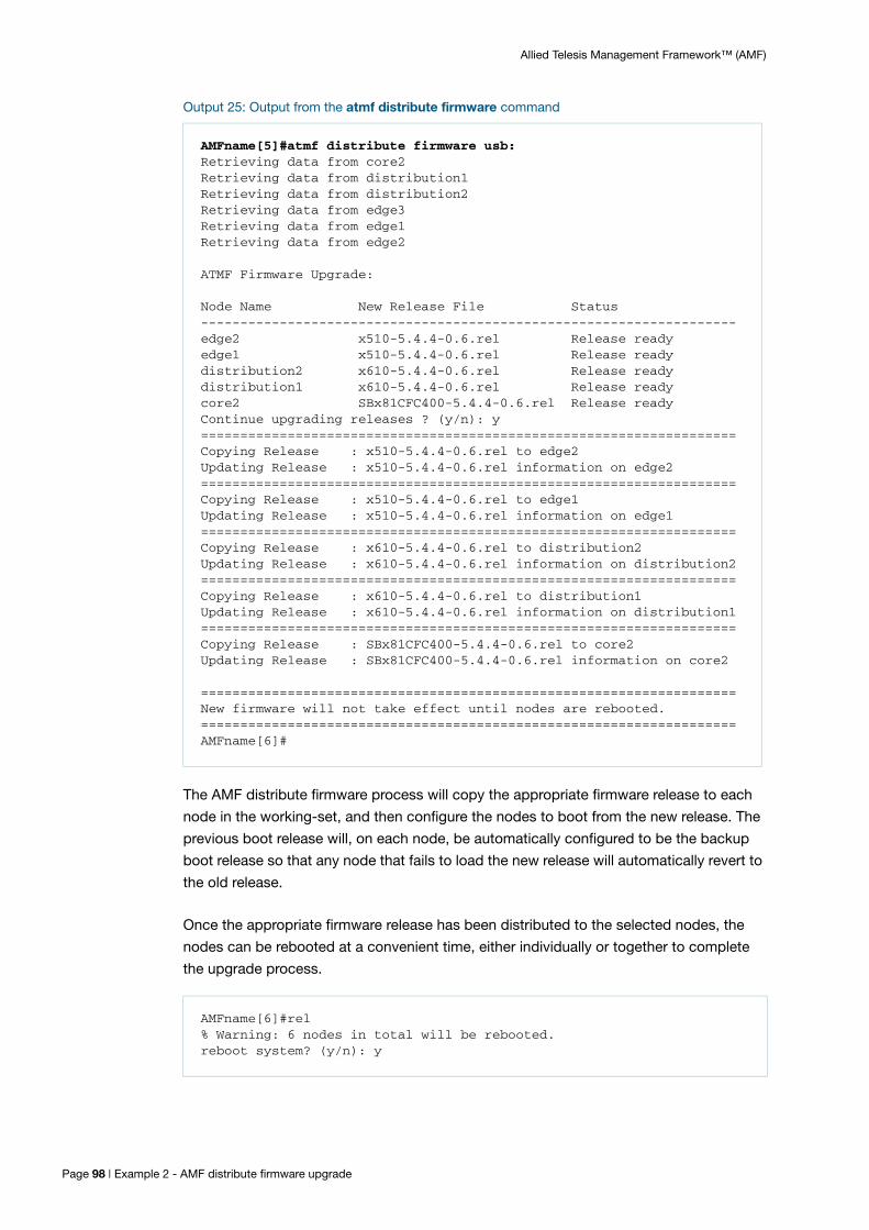
Allied Telesis Management Framework™ (AMF)
Output 25: Output from the atmf distribute firmware command
The AMF distribute firmware process will copy the appropriate firmware release to each
node in the working-set, and then configure the nodes to boot from the new release. The
previous boot release will, on each node, be automatically configured to be the backup
boot release so that any node that fails to load the new release will automatically revert to
the old release.
Once the appropriate firmware release has been distributed to the selected nodes, the
nodes can be rebooted at a convenient time, either individually or together to complete
the upgrade process.
AMFname[5]#atmf distribute firmware usb:Retrieving data from core2Retrieving data from distribution1Retrieving data from distribution2 Retrieving data from edge3Retrieving data from edge1Retrieving data from edge2
ATMF Firmware Upgrade:
Node Name New Release File Status --------------------------------------------------------------------edge2 x510-5.4.4-0.6.rel Release ready edge1 x510-5.4.4-0.6.rel Release ready distribution2 x610-5.4.4-0.6.rel Release ready distribution1 x610-5.4.4-0.6.rel Release ready core2 SBx81CFC400-5.4.4-0.6.rel Release ready Continue upgrading releases ? (y/n): y====================================================================Copying Release : x510-5.4.4-0.6.rel to edge2 Updating Release : x510-5.4.4-0.6.rel information on edge2====================================================================Copying Release : x510-5.4.4-0.6.rel to edge1 Updating Release : x510-5.4.4-0.6.rel information on edge1====================================================================Copying Release : x610-5.4.4-0.6.rel to distribution2 Updating Release : x610-5.4.4-0.6.rel information on distribution2====================================================================Copying Release : x610-5.4.4-0.6.rel to distribution1 Updating Release : x610-5.4.4-0.6.rel information on distribution1====================================================================Copying Release : SBx81CFC400-5.4.4-0.6.rel to core2 Updating Release : SBx81CFC400-5.4.4-0.6.rel information on core2
====================================================================New firmware will not take effect until nodes are rebooted.====================================================================AMFname[6]#
AMFname[6]#rel% Warning: 6 nodes in total will be rebooted.reboot system? (y/n): y
Page 98 | Example 2 - AMF distribute firmware upgrade

Allied Telesis Management Framework™ (AMF)
Node ProvisioningYou can preconfigure (provision) a port for a future node before that node is added to the
network. A provisioned node can be created as a new unique entity, or can be cloned
using the backup data from an existing node. When you connect the new node to the
provisioned port in the AMF network, its configuration is loaded from the information
stored in the backup media.
AMF commands are used to create and configure a provisioned node and to specify the
port(s) that the node is expected to appear on.
When to use node provisioning
Node provisioning can be used in the following instances:
For future extension of the AMF network. You can preconfigure future AMF network
nodes via the atmf provision node commands. The following figure illustrates the
position of a future, provisioned node. Port1.1.5 on Member 2 and port1.0.3 on
Member 4 are configured to expect the future node.
Figure 18: Provisioning for a future node
For replacing an existing node with a node that has a different platform (e.g. replacing
an x310 switch with an x510), and/or with a different host name. Using the atmf
provision node commands you can configure the ports on adjacent nodes to accept
a replacement AMF member.
Note: If you are replacing an existing node that has the same platform and host name, refer to "Node Recovery" on page 73. In this case, node provisioning is not necessary, and node recovery will suffice.
Member 1
Member 2
Member 4
Member 3
port1.0.1
AMF crosslinkAMF up/down link
port1.1.3
port1.1.3port1.0.1
port1.1.2 port1.1.2
port1.1.1
port1.1.2
port1.1.1
port1.1.1
AMFMaster 1
Future node
port1.1.5
port1.0.3
When to use node provisioning | Page 99

Allied Telesis Management Framework™ (AMF)
Creating a new provisioned node
Node provisioning is effectively the process of creating a backup file-set on a master node
that can be loaded onto a provisioned node some time in the future. This file-set is
created just as if the provisioned node really existed and was connected to the network.
Typically these comprise configuration, operating system, and license files etc.
AMF stores these configuration files for the provisioned node on the master node’s
backup media or a remote backup server. These files are automatically loaded onto the
new node’s Flash when it is introduced to the network, in the same way as backed up files
are loaded to the replacement for an existing node.
You can preconfigure nodes either by creating a new directory, or by cloning an existing
node (see Table 1 on page 102 and Table 2 on page 103).
In brief, the operations of the two methods are:
1. Using the command atmf provision node create.
This command creates an “empty” directory ready to hold release and configuration files for use on a future node. You can also copy configuration and release files from existing switches into the new directory.
A convenient way to do this is to use the commands:
atmf provision node <nodename> configure boot config [backup]
[<file-path|URL>]
atmf provision node <nodename> configure boot system [backup]
[<file-path|URL>]
These commands will take a configuration script or operating system image from a specified location, and place it into the file-set for the node that is being provisioned.
Alternatively, you can create the configuration files by using the text editor to edit a configuration script:
Into the file, enter commands similar to those described in "AMF Configuration" on page 31.
Copy the newly created configuration file into the directory that has been created for holding files for this future node, referred to as the 'donor node'. This procedure is described in Table 1 on page 102.
2. Using the command atmf provision node clone.
This command creates a new directory and copies most settings and files from another backed up or provisioned node, referred to as the ‘donor node’. You can make additional changes manually to these files, if needed.
We recommend that you select the donor node to have a configuration as close as possible to that needed on the new node, and for it to contain the same number of ports, or have the same expansion modules (XEMs or LIF cards) installed in the same bays.
This will limit the number of manual changes that will be required to the replicated configuration of the new node.
Page 100 | Creating a new provisioned node

Allied Telesis Management Framework™ (AMF)
When editing or creating files for provisioning, it is convenient to set the working direc-tory to be the directory in which those files reside.
A command that directly sets the working directory to be the storage directory for a given provisioned node is:
atmf provision node <nodename> locate
where <nodename> is the hostname that is being used for the provisioned node.
Configuring adjacent nodes
You need to configure the AMF links and cross-links on the adjacent node before the new
node is connected. Later, when the provisioned node is introduced to the AMF network,
the adjacent node(s) will recognize it and the new node will automatically join the AMF
network.
If you plan to replace an existing AMF node with one that has a different host name, use
the atmf provision command to configure the adjacent node to expect the new node in
the future. This command is used to configure all AMF links and cross-links to the new
node (excluding virtual-links). The command is entered in port configuration mode for the
port to which the provisioned node will be connected. It effectively informs the node that a
provisioned node, with a specified name, will be connected to that port.
If you plan to extend your AMF network via ports that have not been used before, you
must first fully configure the ports beforehand. Such configuration includes using the atmf
provision command and other commands, some of which are shown in the following
tables.
Carry out the procedures outlined in Table 1 on page 102 if you want to achieve the
following situations:
create a provisioned node.
configure the existing node(s) that the provisioned node will (eventually) connect to.
Carry out the procedures outlined in Table 2 on page 103 if you want to achieve the
following situations:
clone a provisioned node.
configure the existing node(s) that the provisioned node will eventually connect to.
Configuring adjacent nodes | Page 101

Allied Telesis Management Framework™ (AMF)
Table 1: Procedure for creating a provisioned node and configuring its adjacent node(s)
1. Enter Privileged Exec mode
Member_4>enable
2. Set the name of the provisioned node to “future_node”
Member_4#atmf provision node future_node create
This command sets up an empty directory on the backup media for use with the provisioned node.
3. Copy and set release file
To copy a release file from Member4’s Flash into the future_node directory, and set that release file to load onto future_node when it first boots up, enter the following commands:
Member_4#atmf provision node future_node locateMember_4#copy flash:member4.rel ./future_node.relMember_4#atmf provision node future_node configure boot system future_node.relORMember_4#atmf provision node future_node locateMember_4#copy current-software member4.rel ./future_node.relMember_4#atmf provision node future_node configure boot system future_node.rel
For information on downloading AlliedWare Plus release files see the Download Centre at www.alliedtelesis.com/support
4. Copy and set the configuration file
To copy a configuration file named current.cfg from Member4’s Flash into the future_node directory, and set that configuration file to load onto future_node when it first boots up, enter the following commands:
Member_4#atmf provision node future_node locateMember_4#copy flash:current.cfg ./future_node.cfgMember_4#atmf provision node future_node configure boot config future_node.cfg
For information on configuring a switch for AMF see "AMF Configuration" on page 31.
5. Edit configuration file if necessary
Note that it is essential to give the provisioned node a unique hostname.For information on configuring a switch for AMF see "AMF Configuration" on page 31.
6. Copy and set license file
To copy a license certificate named member_4.txt from member4’s Flash into the future_node directory, and set that license certificate to load onto future_node when it first boots up, enter the following commands:
Member_4#atmf provision node future_node locateMember_4#copy flash:member_4.txt ./future_node.txtMember_4#atmf provision node future_node license-cert future_node.txt
Page 102 | Configuring adjacent nodes

Allied Telesis Management Framework™ (AMF)
7. On adjacent node(s), configure the port(s) that will be connected to the provisioned node. In this example, port1.0.3 on member4 is being configured as an AMF link and to expect the provisioned node future_node
Member_4#configure terminalMember_4(config)#interface port1.0.3Member_4(config-if)#switchport atmf-linkMember_4(config-if)#switchport trunk native vlan noneMember_4(config-if)#atmf provision future_nodeMember_4(config-if)#exitMember_4(config)#exitMember_4#atmf working-set group local
Note that AMF links and crosslinks do not need to be configured with data VLANs and can be used solely to provide AMF management VLAN redundancy.
Step 7 can be repeated to configure the ports on other adjacent nodes that will be connected to the provisioned node.
Table 2: Procedure for cloning a provisioned node and configuring its adjacent nodes
1. Enter Privileged Exec mode
AMF_Master1>enable
2. Set the name of the provisioned node to “future_node”. In this example, the provisioned node will be a clone of member_3
AMF_Master1#atmf provision node future_node clone member_3
If further changes are required, do, as explained in step 5 in Table 1 above. Note that it is essential to give the provisioned node a unique hostname.
3. On adjacent node(s), configure the port(s) that will be connected to the provisioned node. In this example, port1.0.3 on member_4 is being configured as an AMF link and to expect the provisioned node future_node
AMF_Master1#atmf working-set member_4member_4#configure terminalmember_4(config)#interface port1.0.3member_4(config-if)#switchport atmf-linkmember_4(config-if)#switchport trunk native vlan nonemember_4(config-if)#atmf provision future_nodemember_4(config-if)#exitmember_4(config)#exitmember_4#atmf working-set group localAMF_Master1#
Note that AMF links and crosslinks do not need to be configured with data VLANs and can be used solely to provide AMF management VLAN redundancy.
Step 3 can be repeated to configure the ports on other adjacent nodes to expect the provisioned node.
Table 1: Procedure for creating a provisioned node and configuring its adjacent node(s) (continued)
Configuring adjacent nodes | Page 103

Allied Telesis Management Framework™ (AMF)
Connecting a provisioned node to an AMF network
When you add the new node to the AMF network, its settings and files are automatically
downloaded from the master node’s backup media, or a remote backup server, to the new
node’s Flash.
All you need to do is cable the new device in to the network. The switch’s port LEDs will
flash to show that its settings are being loaded. Progressive strobing of all the port LEDs
indicates that a recovery is underway. For more information on the node recovery LEDs
see "Recovery progress indication" on page 76.
Note that this LED strobing is not available on NGFW products (AR3050S and AR4050S).
The following example shows the expected output when a provisioned node named
future_node joins the AMF network to replace a node called member_5.
21:57:35 awplus ATMF[999]: ATMF network detected 21:57:35 awplus ATMF[999]: ATMF safe config applied (forwarding disabled) 21:57:45 awplus ATMF[999]: Shutting down all non ATMF ports.21:57:45 awplus ATMF[999]: member_5 has left. 0 member in total.21:57:45 x510-2 ATMF[999]: future_node has joined. 1 member in total.21:57:45 x510-2 ATMF[999]: Automatic node recovery started 21:57:45 x510-2 ATMF[999]: Attempting to recover as future_node 21:57:46 x510-2 ATMF[999]: Checking master node availability 21:57:52 x510-2 ATMF[999]: AMF_Master1 has joined. 2 members in total21:57:54 x510-2 ATMF[999]: member_1 has joined. 3 members in total.21:57:56 x510-2 ATMF[999]: member_2 has joined. 4 members in total.21:58:00 x510-2 ATMF[999]: member_3 has joined. 5 members in total.21:58:03 x510-2 ATMF[999]: member_4 has joined. 6 members in total.21:58:04 x510-2 ATMFFSR[6779]: Retrieving recovery data from master node AMF_Master121:58:34 x510-2 ATMFFSR[6779]: Licence installed from certificate.21:58:35 x510-2 ATMFFSR[6779]: File recovery from master node succeeded. Node will now reboot
Page 104 | Connecting a provisioned node to an AMF network

Allied Telesis Management Framework™ (AMF)
Special Considerations when Using LACP Aggregations as AMF LinksUsing LACP aggregations as AMF links requires specific default behavior on the part of
AMF nodes.
AMF requires that a completely unconfigured node, when attached to an AMF network,
will successfully form an AMF connection, and become integrated into the network.
So, if the unconfigured node is attached to the network by an LACP aggregation, it must
be possible for the unconfigured node to form an LACP aggregation.
Therefore AMF nodes need, by default, to be able to recognize when the connected ports
on a neighbor device are dynamically (LACP) aggregated, and then to negotiate an
aggregated link with that neighbor's ports.
Specific functionality is available in Alliedware Plus to support this default behavior, called
LACP global passive mode.
LACP global passive mode
AlliedWare Plus devices can self-configure LACP channel-groups dynamically when they
are connected to another device that has LACP channel-groups configured with active
mode.
When a device starts with factory default configuration (or the start-up configuration file is
missing), LACP global passive mode is automatically turned on. This is useful if you want
to attach a new device to an existing LACP configured network, because the newly added
device will then automatically form LACP channel-groups.
This feature can be turned on or off by the following CLI commands in global
configuration mode:
lacp global-passive-mode enable
no lacp global-passive-mode enable
The current configuration setting is displayed by using the command show running-
config.
Dynamically learned LACP channel-groups behave the same as manually configured ones
(that are configured by the channel-group command). The only exception is that
dynamically learned LACP channel-groups are not displayed in the running configuration.
Currently known—both dynamically created and manually configured —LACP channel-
groups are displayed by entering the following commands:
show etherchannel
show etherchannel detail
LACP global passive mode | Page 105

Dynamically learned LACP channel-groups
A dynamically learned LACP channel-group will be removed from the port, in any of the
following situations:
LACP global passive mode is turned off
the port is removed (hot-swapped out)
the port is down
the no channel-group command is executed on that port.
A dynamically learned LACP channel-group will become a normal, manually configured,
LACP channel-group and appear in the running configuration, in any of the following
situations:
if you add any configuration in Interface Configuration mode of the aggregation or any
member of the aggregation
if you execute the channel-group command in any member of the aggregation, or
if you add a new port to the aggregation.
Mixed LACP configuration (manual and dynamic)
When LACP global passive mode is turned on—by using the lacp global-passive-mode
enable command—we do not recommend using a mixed configuration in an LACP
channel-group; i.e. where some links are manually configured and others are dynamically
learned in the same channel-group.
C613-22047-00 REV G
NETWORK SMARTER
alliedtelesis.com
North America Headquarters | 19800 North Creek Parkway | Suite 100 | Bothell | WA 98011 | USA | T: +1 800 424 4284 | F: +1 425 481 3895
Asia-Pacific Headquarters | 11 Tai Seng Link | Singapore | 534182 | T: +65 6383 3832 | F: +65 6383 3830
EMEA & CSA Operations | Incheonweg 7 | 1437 EK Rozenburg | The Netherlands | T: +31 20 7950020 | F: +31 20 7950021
© 2016 Allied Telesis, Inc. All rights reserved. Information in this document is subject to change without notice. All company names, logos, and product designs that are trademarks or registered trademarks are the property of their respective owners.