Embed Size (px)
Citation preview
7/29/2019 AMI Mesh Editing Tutorial
http://slidepdf.com/reader/full/ami-mesh-editing-tutorial 1/29
Autodesk® Moldflow® Insight 2012
AMI Mesh Editing Tutorial

7/29/2019 AMI Mesh Editing Tutorial
http://slidepdf.com/reader/full/ami-mesh-editing-tutorial 2/29
Revision 1, 30 March 2012.
This document contains Autodesk and third-party software license agreements/notices and/or additional terms and conditions for licensedthird-party software components included within the product. These notices and/or additional terms and conditions are made a part of andincorporated by reference into the Autodesk Software License Agreement and/or the About included as part of the Help function within thesoftware.
7/29/2019 AMI Mesh Editing Tutorial
http://slidepdf.com/reader/full/ami-mesh-editing-tutorial 3/29
Contents
Opening a project. . . . . . . . . . . . . . . . . . . . . . . . . . . . . . . . . . . . . 1Chapter 1
Interpreting mesh statistics. . . . . . . . . . . . . . . . . . . . . . . . . . . . . 2Chapter 2
Fixing bad connectivity. . . . . . . . . . . . . . . . . . . . . . . . . . . . . . . . 4Chapter 3
Fixing high aspect ratios. . . . . . . . . . . . . . . . . . . . . . . . . . . . . . . 9Chapter 4
Fixing invalid free edges. . . . . . . . . . . . . . . . . . . . . . . . . . . . . . . 15Chapter 5
Fixing intersecting elements. . . . . . . . . . . . . . . . . . . . . . . . . . . 19Chapter 6
Tutorial review. . . . . . . . . . . . . . . . . . . . . . . . . . . . . . . . . . . . . . . 25Chapter 7
iii

7/29/2019 AMI Mesh Editing Tutorial
http://slidepdf.com/reader/full/ami-mesh-editing-tutorial 4/29
iv
7/29/2019 AMI Mesh Editing Tutorial
http://slidepdf.com/reader/full/ami-mesh-editing-tutorial 5/29
1
Opening a project
In this task, you will create a project and import a model with a prepared mesh.
1 From the green Moldflow M drop-down menu, click (Close > Project) to closeany project you may have open.
2 Click (Get Started tab > Launch panel > Import).
3 Navigate to the Tutorial folder where Autodesk Moldflow Insight is installed, typically
C:\Program Files\Autodesk\Moldflow Insight xxxx\tutorial.4 In the Files of Type drop-down list, select Study Files *.sdy.
5 Click on the file tutorial_3_task_1.sdy and click Open.
The Import—Create Project dialog appears.
6 Enter Tutorial 3 for the Project name in the Import dialog and click OK.
7 You will see from the Study Tasks pane that the model in this task is represented bya Dual Domain mesh.
8 Select (View tab > Navigate panel > Orbit) and rotate the model to examine itsgeometry and features.
9 If necessary, resize the model using the (View tab > Navigate panel > Zoom) tool.
In the next task, you will check the quality of the mesh by creating the Mesh Statisticsreport.
Click the Next topic link below to move on to the next task of the tutorial.
1
7/29/2019 AMI Mesh Editing Tutorial
http://slidepdf.com/reader/full/ami-mesh-editing-tutorial 6/29
2
Interpreting mesh statistics
In this task, you will complete the following steps to interpret mesh statistics.
■ Open the Mesh Statistics dialog for the study opened in the previous task
■ Examine the results in detail
■ Determine whether there are any problems in the mesh
1 Open the tutorial_3_task_1 study from the Tutorial 3 project you created
in the previous task.
2 Click (Home tab > Create panel > Mesh) to open the Mesh tab.
3 Click (Mesh tab > Mesh Diagnostics panel > Mesh Statistics).
The Mesh Statistics dialog appears.
4 Examine the results based on what you learned in the Meshing tutorial.
Do any of the results suggest problems with the mesh? Refer to the discussionbelow to confirm your interpretation of the results.
5 When you have finished reviewing the results, click Close.
The results confirm that the part is meshed, and that there are
no 2D features (runners, cooling channels) in the model. The fact
Entity Counts
that two connectivity regions are reported is a matter of concern- the part should consist of only a single connected region. Youwill investigate and eliminate this problem in Task 3.
For a Midplane mesh, free edges are expected on the edges of thepart. For a Dual Domain or 3D mesh, however, no free edges
Edge Details
should be reported. The results report 54 free edges. As this is aDual Domain mesh, there are defects to be repaired. You willcorrect this type of problem in Task 5.
This result is relevant to Midplane and Dual Domain meshes.Autodesk Moldflow Insight assigns a unique number to each node
OrientationDetails
and element for identification purposes. To determine if an
element is oriented correctly, the "Right hand rule" is applied.For an individual element, the fingers of the right hand curl inthe direction of the ascending node number. The direction of thethumb indicates the outer face. All elements on a surface mustbe oriented correctly. For a Dual Domain mesh, the "top" side of the elements should be pointing outward. When all elements inthe mesh are oriented correctly, the Orientation Details resultwill be zero, as in this case.
2 | Interpreting mesh statistics

7/29/2019 AMI Mesh Editing Tutorial
http://slidepdf.com/reader/full/ami-mesh-editing-tutorial 7/29
Regardless of the mesh type, a value other than zero for any of the results in this section indicates problems in the mesh. Three
IntersectionDetails
intersecting elements are reported for mesh in this example. Youwill learn how to fix this type of error in Task 6.
The concept of triangle aspect ratios was explained in the Meshingtutorial. Ideally, the aspect ratio of all triangular elements should
SurfaceTriangleAspect Ratio be less than 6. The maximum aspect ratio in this model is reported
as about 11. You will learn how to reduce aspect ratios in Task 4.
This section only appears for Dual Domain meshes. The resultsindicate that the matching between the elements representing
MatchPercentage
the top and bottom surfaces of the part is more than the required85 percent.
In the next task, you will fix the connectivity problem identified above.
Click the Next topic link below to move on to the next task of the tutorial.
Interpreting mesh statistics |3

7/29/2019 AMI Mesh Editing Tutorial
http://slidepdf.com/reader/full/ami-mesh-editing-tutorial 8/29
3
Fixing bad connectivity
In this task, you will use various tools to manually repair poor connectivity regions of thestudy.
Ensure the tutorial_3_task_1 study from the Tutorial 3 project you created inTask 1 is open.
Connectivity Regions: Create Triangles
1 Using the ViewCube, select Top View .
2 Click (Home tab > Create panel > Mesh) to open the Mesh tab.
3 Click (Mesh tab > Mesh Diagnostics panel > Connectivity) to display themesh Connectivity Diagnostic dialog.
4 Click on any element of the model to serve as the reference element for theconnectivity check.
5 In the Connectivity Diagnostic pane, select Place results in diagnostics layer.
When the diagnostic is run, this step will ensure that any unconnected elementsare placed in their own separate layer. This will help you identify and deal withthe problem elements.
6 Click Show and then click Close.The connectivity plot shows that there is a group of elements in the top left of the model which are disconnected from the rest of the part.
7 Click (View tab > Navigate panel > Zoom Window) and draw a box aroundthe circular area of disconnected elements.
8 Click (View tab > Navigate panel > Center) and then click in the center of the circle of disconnected elements.
9 Click (View tab > Navigate panel > Orbit) and examine the connectivityproblem.
Notice that the disk area is supposed to be connected to the main body of thepart at four openings, one of which is shown in Step 16 below. To eliminate theconnectivity problem, you need to connect the disk to the main part at thesefour locations.
4 | Fixing bad connectivity
7/29/2019 AMI Mesh Editing Tutorial
http://slidepdf.com/reader/full/ami-mesh-editing-tutorial 9/29
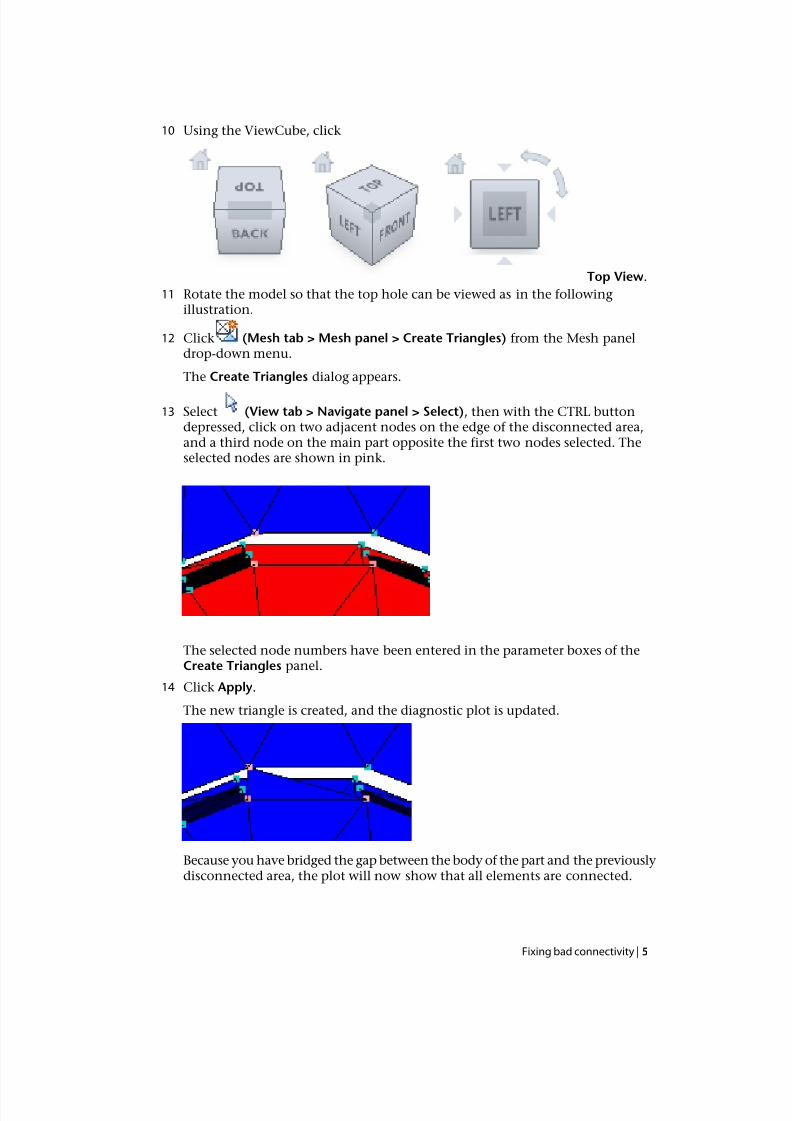
10 Using the ViewCube, click
Top View.
11 Rotate the model so that the top hole can be viewed as in the followingillustration.
12 Click (Mesh tab > Mesh panel > Create Triangles) from the Mesh paneldrop-down menu.
The Create Triangles dialog appears.
13 Select (View tab > Navigate panel > Select), then with the CTRL buttondepressed, click on two adjacent nodes on the edge of the disconnected area,and a third node on the main part opposite the first two nodes selected. Theselected nodes are shown in pink.
The selected node numbers have been entered in the parameter boxes of theCreate Triangles panel.
14 Click Apply.
The new triangle is created, and the diagnostic plot is updated.
Because you have bridged the gap between the body of the part and the previouslydisconnected area, the plot will now show that all elements are connected.
Fixing bad connectivity | 5
7/29/2019 AMI Mesh Editing Tutorial
http://slidepdf.com/reader/full/ami-mesh-editing-tutorial 10/29
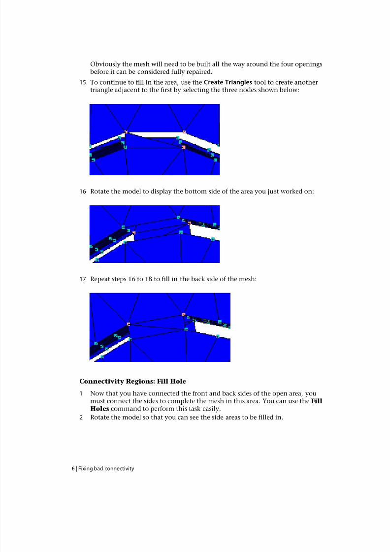
Obviously the mesh will need to be built all the way around the four openingsbefore it can be considered fully repaired.
15 To continue to fill in the area, use the Create Triangles tool to create anothertriangle adjacent to the first by selecting the three nodes shown below:
16 Rotate the model to display the bottom side of the area you just worked on:
17 Repeat steps 16 to 18 to fill in the back side of the mesh:
Connectivity Regions: Fill Hole
1 Now that you have connected the front and back sides of the open area, youmust connect the sides to complete the mesh in this area. You can use the FillHoles command to perform this task easily.
2 Rotate the model so that you can see the side areas to be filled in.
6 | Fixing bad connectivity
7/29/2019 AMI Mesh Editing Tutorial
http://slidepdf.com/reader/full/ami-mesh-editing-tutorial 11/29
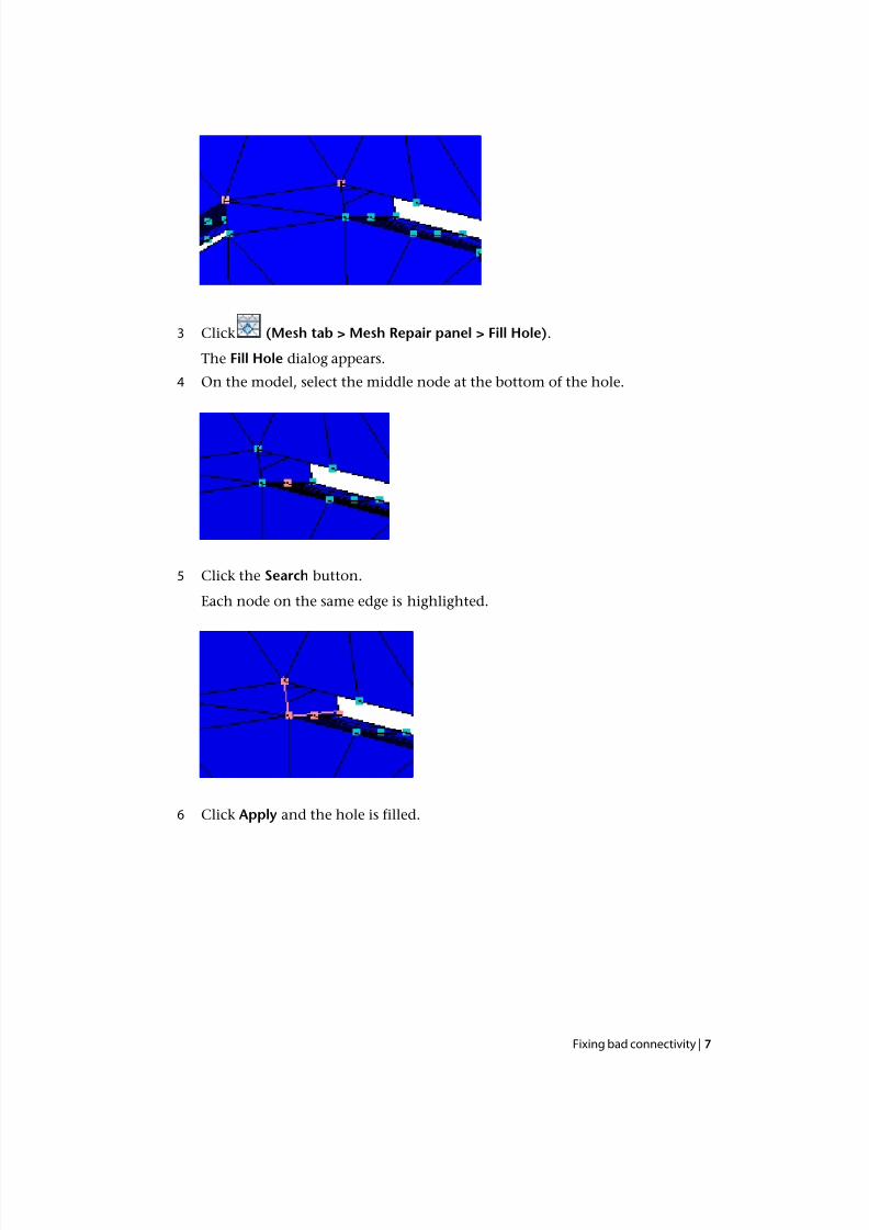
3 Click (Mesh tab > Mesh Repair panel > Fill Hole).
The Fill Hole dialog appears.
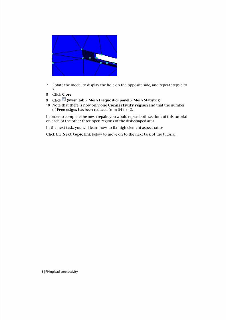
4 On the model, select the middle node at the bottom of the hole.
5 Click the Search button.
Each node on the same edge is highlighted.
6 Click Apply and the hole is filled.
Fixing bad connectivity | 7
7/29/2019 AMI Mesh Editing Tutorial
http://slidepdf.com/reader/full/ami-mesh-editing-tutorial 12/29
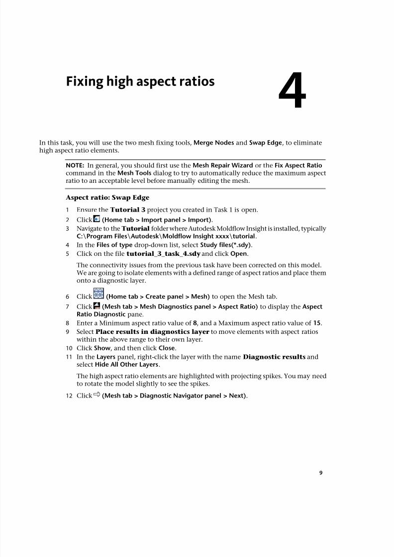
7 Rotate the model to display the hole on the opposite side, and repeat steps 5 to7.
8 Click Close.
9 Click (Mesh tab > Mesh Diagnostics panel > Mesh Statistics).
10 Note that there is now only one Connectivity region and that the numberof Free edges has been reduced from 54 to 42.
In order to complete the mesh repair, you would repeat both sections of this tutorialon each of the other three open regions of the disk-shaped area.
In the next task, you will learn how to fix high element aspect ratios.
Click the Next topic link below to move on to the next task of the tutorial.
8 | Fixing bad connectivity
7/29/2019 AMI Mesh Editing Tutorial
http://slidepdf.com/reader/full/ami-mesh-editing-tutorial 13/29
4
Fixing high aspect ratios
In this task, you will use the two mesh fixing tools, Merge Nodes and Swap Edge, to eliminatehigh aspect ratio elements.
NOTE: In general, you should first use the Mesh Repair Wizard or the Fix Aspect Ratiocommand in the Mesh Tools dialog to try to automatically reduce the maximum aspectratio to an acceptable level before manually editing the mesh.
Aspect ratio: Swap Edge
1 Ensure the Tutorial 3 project you created in Task 1 is open.
2 Click (Home tab > Import panel > Import).
3 Navigate to the Tutorial folder where Autodesk Moldflow Insight is installed, typicallyC:\Program Files\Autodesk\Moldflow Insight xxxx\tutorial.
4 In the Files of type drop-down list, select Study files(*.sdy).
5 Click on the file tutorial_3_task_4.sdy and click Open.
The connectivity issues from the previous task have been corrected on this model.We are going to isolate elements with a defined range of aspect ratios and place themonto a diagnostic layer.
6 Click (Home tab > Create panel > Mesh) to open the Mesh tab.
7 Click (Mesh tab > Mesh Diagnostics panel > Aspect Ratio) to display the AspectRatio Diagnostic pane.
8 Enter a Minimum aspect ratio value of 8, and a Maximum aspect ratio value of 15.
9 Select Place results in diagnostics layer to move elements with aspect ratioswithin the above range to their own layer.
10 Click Show, and then click Close.
11 In the Layers panel, right-click the layer with the name Diagnostic results andselect Hide All Other Layers.
The high aspect ratio elements are highlighted with projecting spikes. You may needto rotate the model slightly to see the spikes.
12 Click (Mesh tab > Diagnostic Navigator panel > Next).
9
7/29/2019 AMI Mesh Editing Tutorial
http://slidepdf.com/reader/full/ami-mesh-editing-tutorial 14/29
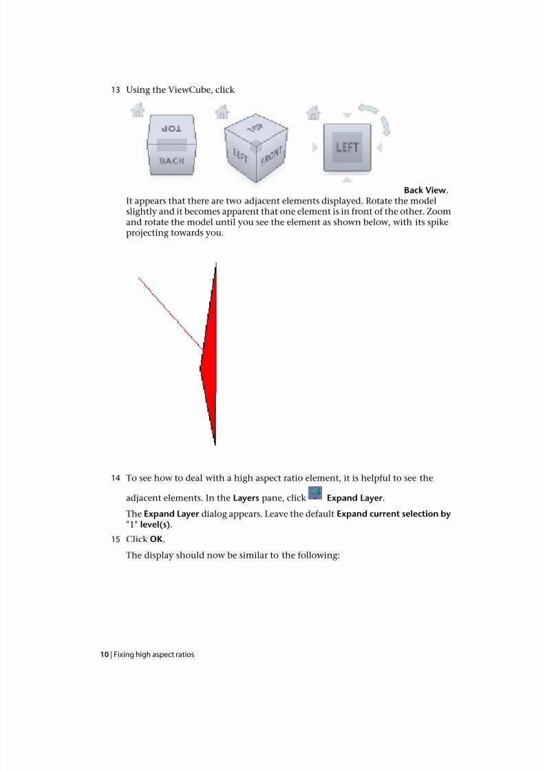
13 Using the ViewCube, click
Back View.It appears that there are two adjacent elements displayed. Rotate the modelslightly and it becomes apparent that one element is in front of the other. Zoomand rotate the model until you see the element as shown below, with its spikeprojecting towards you.
14 To see how to deal with a high aspect ratio element, it is helpful to see the
adjacent elements. In the Layers pane, click Expand Layer.
The Expand Layer dialog appears. Leave the default Expand current selection by"1" level(s).
15 Click OK.The display should now be similar to the following:
10 | Fixing high aspect ratios
7/29/2019 AMI Mesh Editing Tutorial
http://slidepdf.com/reader/full/ami-mesh-editing-tutorial 15/29
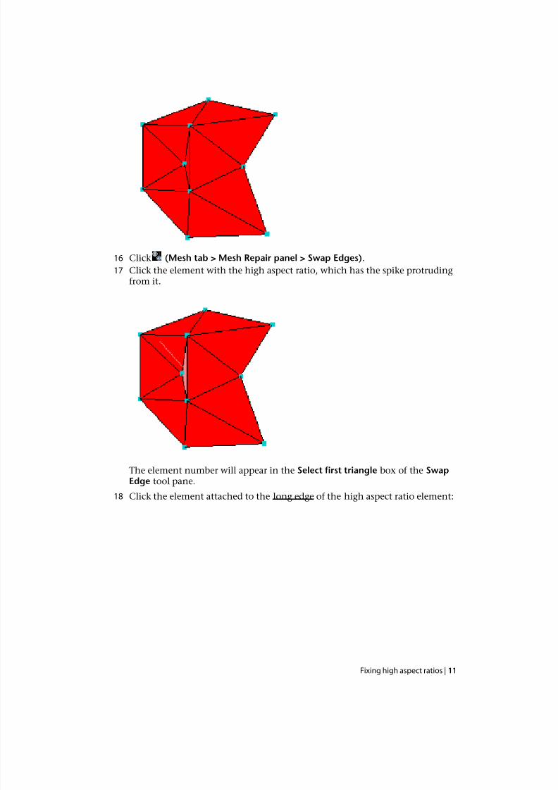
16 Click (Mesh tab > Mesh Repair panel > Swap Edges).
17 Click the element with the high aspect ratio, which has the spike protrudingfrom it.
The element number will appear in the Select first triangle box of the SwapEdge tool pane.
18 Click the element attached to the long edge of the high aspect ratio element:
Fixing high aspect ratios | 11
7/29/2019 AMI Mesh Editing Tutorial
http://slidepdf.com/reader/full/ami-mesh-editing-tutorial 16/29
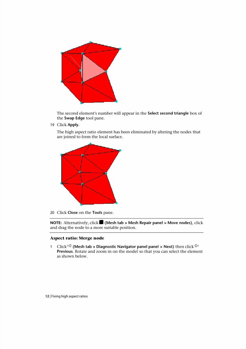
The second element's number will appear in the Select second triangle box of the Swap Edge tool pane.
19 Click Apply.
The high aspect ratio element has been eliminated by altering the nodes thatare joined to form the local surface.
20 Click Close on the Tools pane.
NOTE: Alternatively, click (Mesh tab > Mesh Repair panel > Move nodes), clickand drag the node to a more suitable position.
Aspect ratio: Merge node
1 Click (Mesh tab > Diagnostic Navigator panel panel > Next) then clickPrevious. Rotate and zoom in on the model so that you can select the elementas shown below.
12 | Fixing high aspect ratios
7/29/2019 AMI Mesh Editing Tutorial
http://slidepdf.com/reader/full/ami-mesh-editing-tutorial 17/29
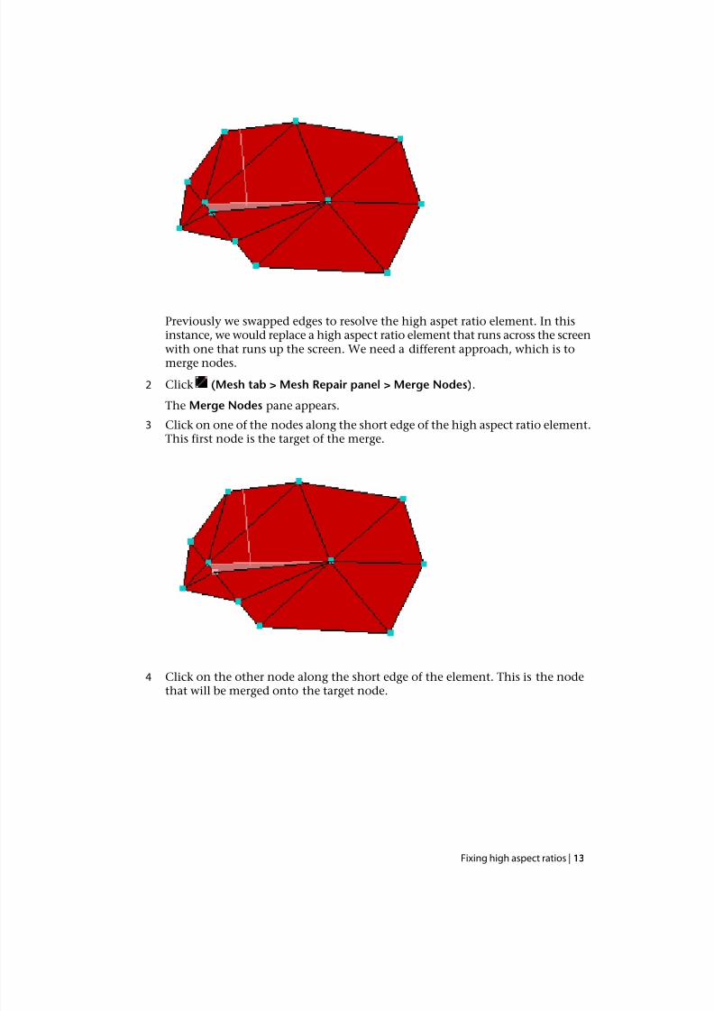
Previously we swapped edges to resolve the high aspet ratio element. In thisinstance, we would replace a high aspect ratio element that runs across the screen
with one that runs up the screen. We need a different approach, which is tomerge nodes.
2 Click (Mesh tab > Mesh Repair panel > Merge Nodes).
The Merge Nodes pane appears.
3 Click on one of the nodes along the short edge of the high aspect ratio element.This first node is the target of the merge.
4 Click on the other node along the short edge of the element. This is the nodethat will be merged onto the target node.
Fixing high aspect ratios | 13
7/29/2019 AMI Mesh Editing Tutorial
http://slidepdf.com/reader/full/ami-mesh-editing-tutorial 18/29
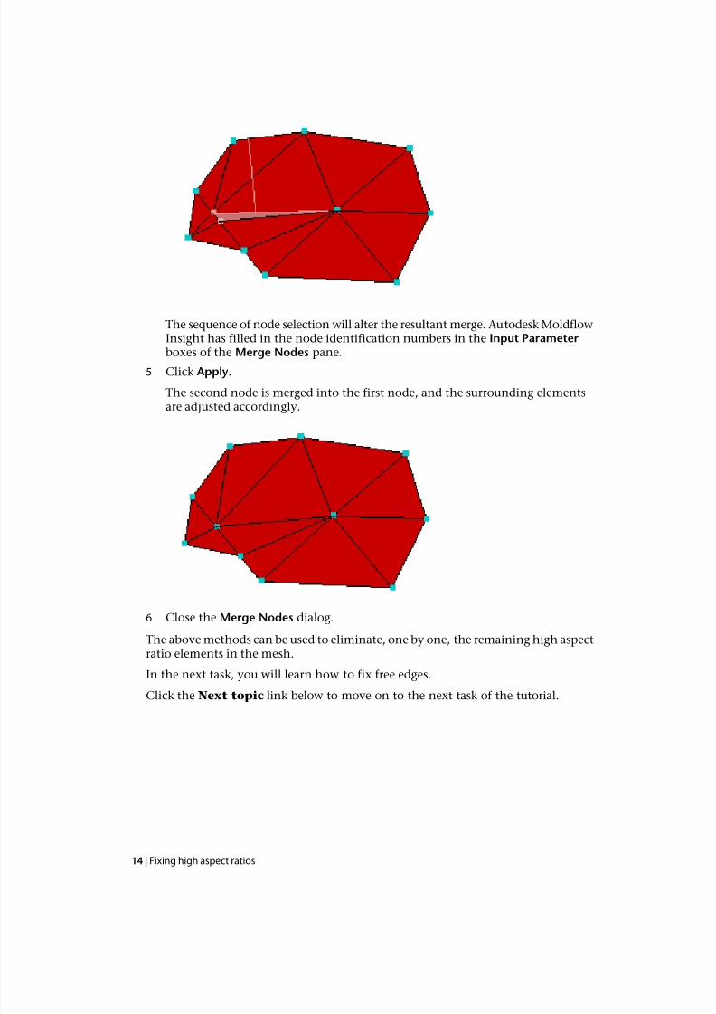
The sequence of node selection will alter the resultant merge. Autodesk MoldflowInsight has filled in the node identification numbers in the Input Parameter
boxes of the Merge Nodes pane.5 Click Apply.
The second node is merged into the first node, and the surrounding elementsare adjusted accordingly.
6 Close the Merge Nodes dialog.
The above methods can be used to eliminate, one by one, the remaining high aspectratio elements in the mesh.
In the next task, you will learn how to fix free edges.
Click the Next topic link below to move on to the next task of the tutorial.
14 | Fixing high aspect ratios
7/29/2019 AMI Mesh Editing Tutorial
http://slidepdf.com/reader/full/ami-mesh-editing-tutorial 19/29
5
Fixing invalid free edges
In this task, you will use the Mesh editing tools to eliminate the Free Edges indicated in the MeshStatistics dialog.
1 Ensure the Tutorial 3 project you created in Task 1 is open.
2 Click then Open > Import and import the file tutorial_free_edges.sdyfrom the Tutorial folder, typically C:\Program Files\Autodesk\Moldflow
Insight xxxx\tutorial
3 Click (Mesh tab > Mesh Diagnostics panel > Free Edges) .
4 Select the Place results in diagnostics layer checkbox.
5 Click Show , and then click Close.
6 In the Layers pane, right-click on Diagnostic results and select Hide All OtherLayers.
Three groups of problem elements consisting of nine free edges are present.
7 Click Expand Layer from the top of the Layers panel, accept the defaults, andclick OK.
8 Enter the values 40 -25 -5 in the Rotation Angle text box (View tab> Viewpoint panel), and press Enter to rotate the model.
9 Click (Mesh tab > Diagnostic Navigator panel > Start - First Diagnostic).
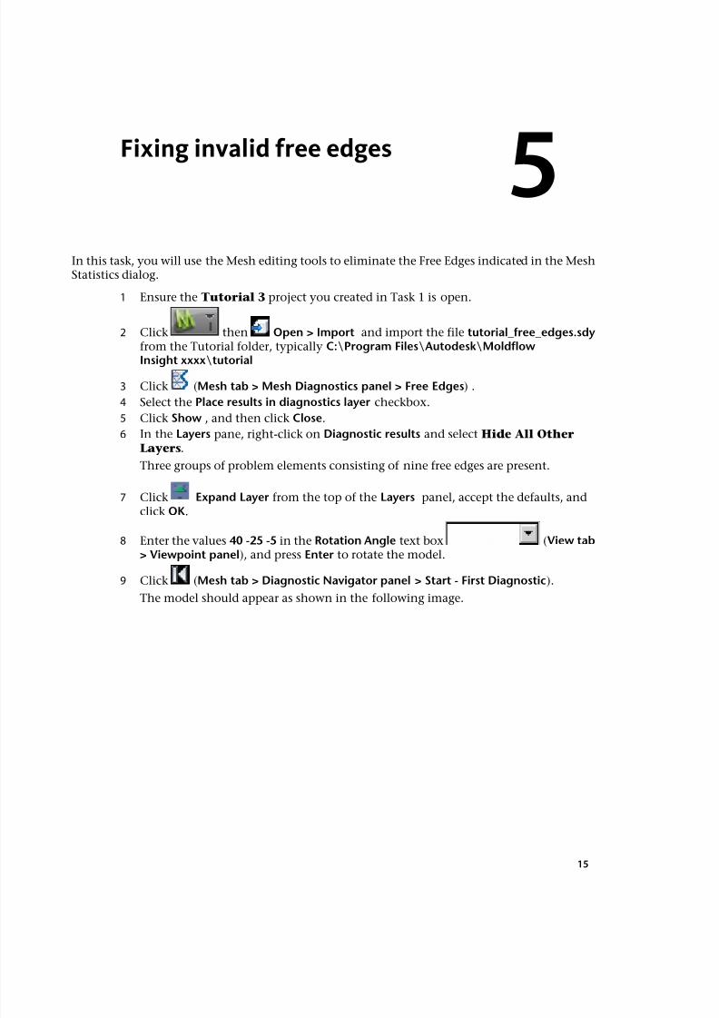
The model should appear as shown in the following image.
15
7/29/2019 AMI Mesh Editing Tutorial
http://slidepdf.com/reader/full/ami-mesh-editing-tutorial 20/29
Three edges need stitching, one for each of the adjacent triangles. There is a veryfine gap between the triangles that cannot be detected visually.
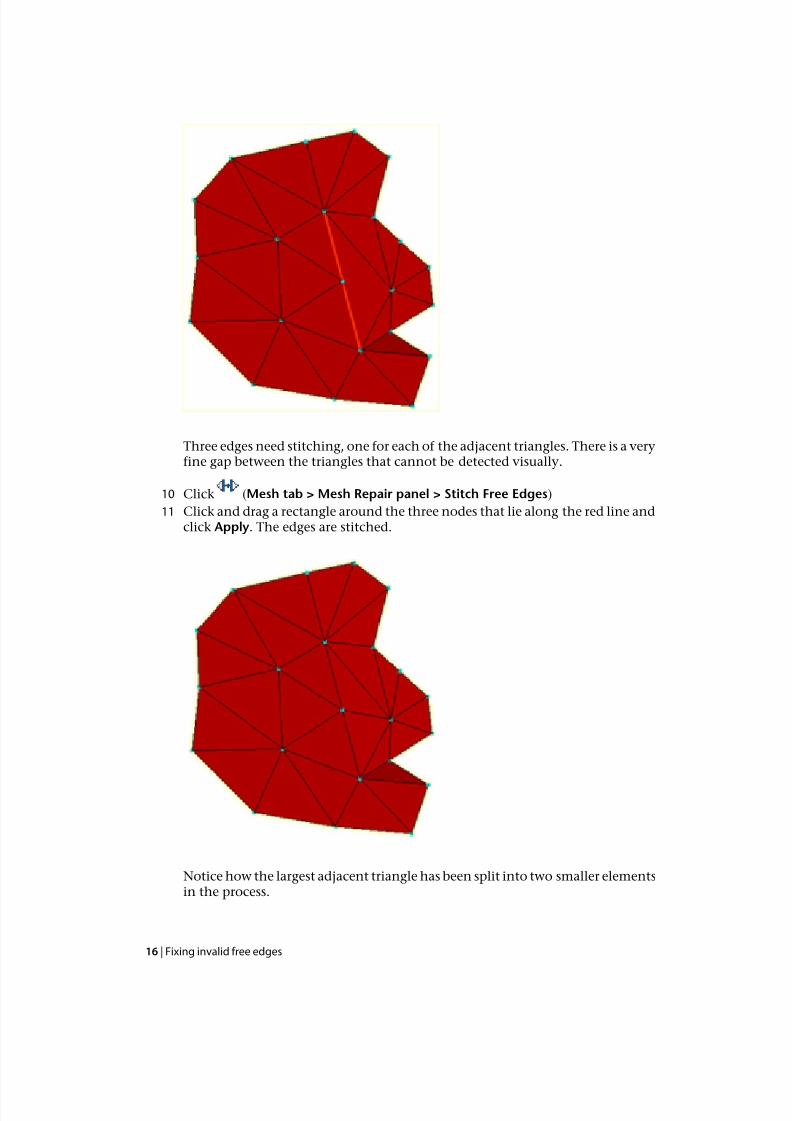
10 Click (Mesh tab > Mesh Repair panel > Stitch Free Edges)
11 Click and drag a rectangle around the three nodes that lie along the red line andclick Apply. The edges are stitched.
Notice how the largest adjacent triangle has been split into two smaller elementsin the process.
16 | Fixing invalid free edges

7/29/2019 AMI Mesh Editing Tutorial
http://slidepdf.com/reader/full/ami-mesh-editing-tutorial 21/29
12 Press (Next) on the Diagnostic Navigator panel (View tab > DiagnosticNavigator panel).
You can also hold down the Ctrl key and select individual nodes along the edge
instead of dragging a rectangle around the free edges.13 The Stitch Free Edges tool pane should still be open. With the Ctrl key held
down, click on the nodes along the free edge and then click Apply.
14 Click (View tab > Diagnostic Navigator panel > End) and rotate the modelto 40 -140 -55.
It is not appropriate to stitch this triangle. Instead you could use the Fill Hole orCreate Triangles as you did in an earlier task. You will use Create Triangles in
this instance.
15 Click (Mesh tab > Mesh panel > Create Triangles).
16 Select Automatically apply when selection complete. When three appropriatenodes are selected, the triangle will be generated without the need to click theApply button.
17 Select the three corner nodes of the hole. The element is added to the modelautomatically.
Fixing invalid free edges | 17

7/29/2019 AMI Mesh Editing Tutorial
http://slidepdf.com/reader/full/ami-mesh-editing-tutorial 22/29
18 Click Mesh tab>
Mesh Diagnostics panel>
Mesh Statistics to verify that allfree edges have been removed.
Click the Next topic link below to move on to the next task of the tutorial.
18 | Fixing invalid free edges
7/29/2019 AMI Mesh Editing Tutorial
http://slidepdf.com/reader/full/ami-mesh-editing-tutorial 23/29
6
Fixing intersecting elements
In this task you will complete steps to fix intesecting elements.
In this task, you will:
■ Use two different techniques to repair intersecting elements.
■ Use a transparent layer to help view the model.
■ Review the Mesh Statistics after repairing a mesh.
Intersecting mesh elements are triangles that touch each other at locations other thanedges and nodes. You need to fix intersecting elements before attempting to analyze yourmodel. These errors are reported in the Mesh Statistics dialog.
Fix Intersecting Elements—Delete and Fill
1 Ensure the Tutorial 3 project you created in Task 1 is open.
2 Click (Home tab > Import panel > Import) and import the file base_mesh.sdy fromthe Tutorial folder, typically C:\Program Files\Autodesk\MoldflowInsight xxxx\tutorial.
3 Click (Home tab > Create panel > Mesh) to open the Mesh tab.
4 Click (Mesh tab > Mesh Diagnostics panel > Mesh Statistics).
Note there are 2 Fully overlapping elements. Click Close.
5 Click (Mesh tab > Mesh Diagnostics panel > Overlap).
6 Select Place results in diagnostics layer.
7 Click Show , and then click Close.
8 In the Layers pane, right-click the Diagnostic results layer and select Hide All OtherLayers.
9 Click Expand Layer, accept the default, and click OK.
Two pairs of intersecting elements should now be visible.
To help visualize where these overlaps occur within the model, you will now createa transparent layer.
10 Select the New Triangles checkbox in the Layers panel.
11 Click Layer Display from the toolbar across the top of the Layers panel.
12 Select Transparent from the Show as drop-down list and click Close.
19
7/29/2019 AMI Mesh Editing Tutorial
http://slidepdf.com/reader/full/ami-mesh-editing-tutorial 24/29
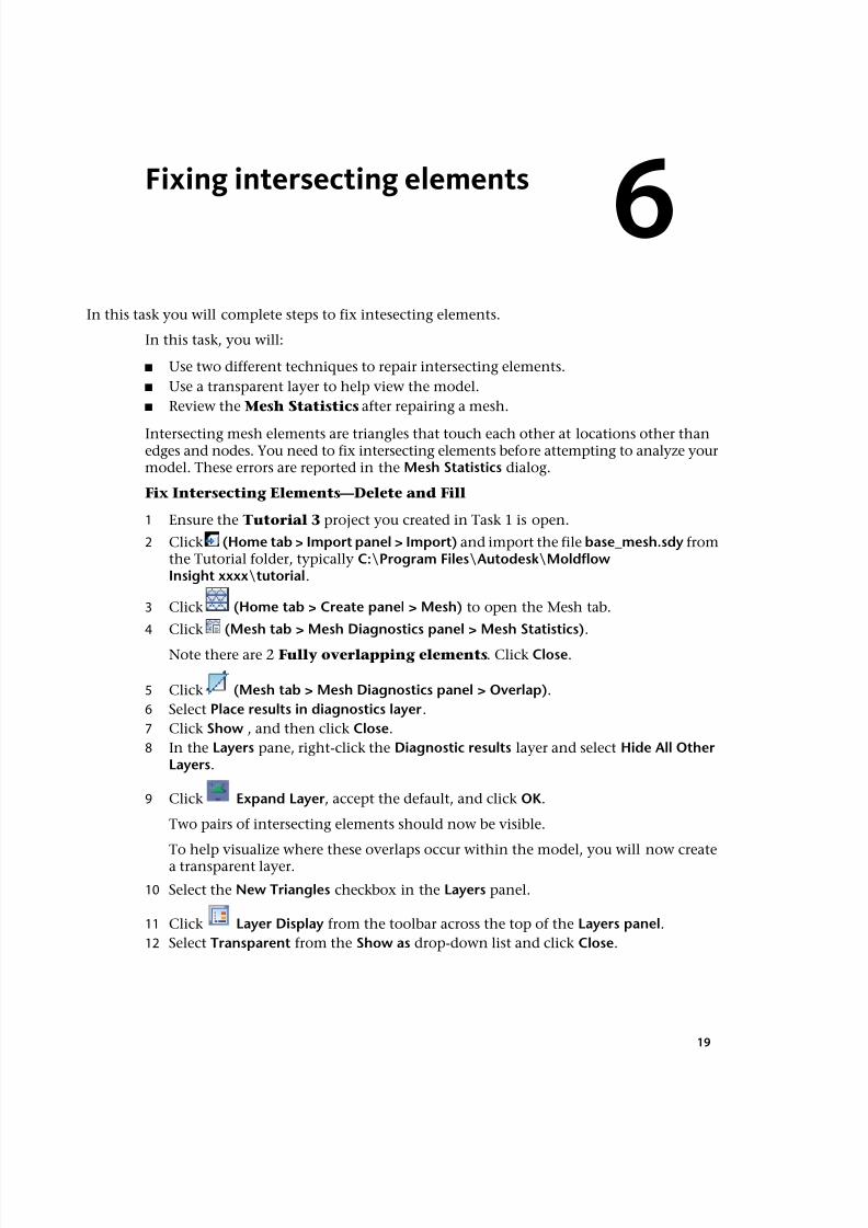
13 Enter the values -155 145 -75 in the Rotation Angles text box (View tab >
Viewpoint panel > Rotation Angles), and press Enter to rotate the model.
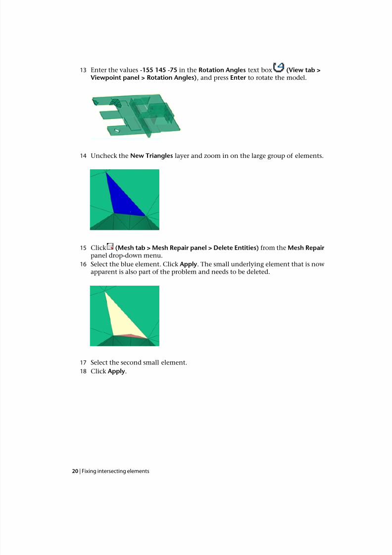
14 Uncheck the New Triangles layer and zoom in on the large group of elements.
15 Click (Mesh tab > Mesh Repair panel > Delete Entities) from the Mesh Repairpanel drop-down menu.
16 Select the blue element. Click Apply. The small underlying element that is nowapparent is also part of the problem and needs to be deleted.
17 Select the second small element.
18 Click Apply.
20 | Fixing intersecting elements
7/29/2019 AMI Mesh Editing Tutorial
http://slidepdf.com/reader/full/ami-mesh-editing-tutorial 25/29
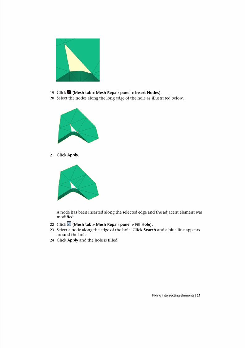
19 Click (Mesh tab > Mesh Repair panel > Insert Nodes).
20 Select the nodes along the long edge of the hole as illustrated below.
21 Click Apply.
A node has been inserted along the selected edge and the adjacent element wasmodified.
22 Click (Mesh tab > Mesh Repair panel > Fill Hole).
23 Select a node along the edge of the hole. Click Search and a blue line appearsaround the hole.
24 Click Apply and the hole is filled.
Fixing intersecting elements | 21
7/29/2019 AMI Mesh Editing Tutorial
http://slidepdf.com/reader/full/ami-mesh-editing-tutorial 26/29
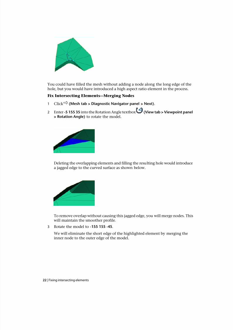
You could have filled the mesh without adding a node along the long edge of thehole, but you would have introduced a high aspect ratio element in the process.
Fix Intersecting Elements— Merging Nodes
1 Click (Mesh tab > Diagnostic Navigator panel > Next).
2 Enter -5 155 35 into the Rotation Angle textbox (View tab > Viewpoint panel> Rotation Angle) to rotate the model.
Deleting the overlapping elements and filling the resulting hole would introducea jagged edge to the curved surface as shown below.
To remove overlap without causing this jagged edge, you will merge nodes. Thiswill maintain the smoother profile.
3 Rotate the model to -155 155 -45.
We will eliminate the short edge of the highlighted element by merging theinner node to the outer edge of the model.
22 | Fixing intersecting elements
7/29/2019 AMI Mesh Editing Tutorial
http://slidepdf.com/reader/full/ami-mesh-editing-tutorial 27/29
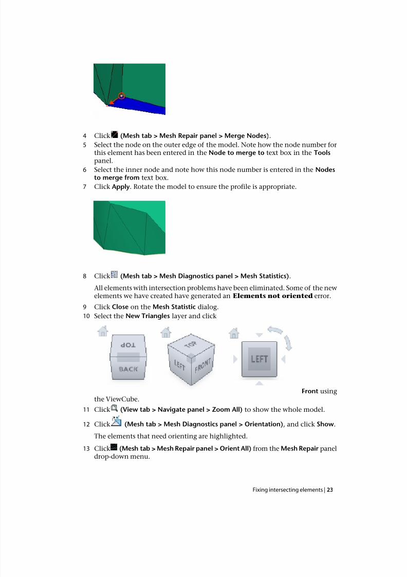
4 Click (Mesh tab > Mesh Repair panel > Merge Nodes).
5 Select the node on the outer edge of the model. Note how the node number forthis element has been entered in the Node to merge to text box in the Toolspanel.
6 Select the inner node and note how this node number is entered in the Nodesto merge from text box.
7 Click Apply. Rotate the model to ensure the profile is appropriate.
8 Click (Mesh tab > Mesh Diagnostics panel > Mesh Statistics).
All elements with intersection problems have been eliminated. Some of the newelements we have created have generated an Elements not oriented error.
9 Click Close on the Mesh Statistic dialog.
10 Select the New Triangles layer and click
Front usingthe ViewCube.
11 Click (View tab > Navigate panel > Zoom All) to show the whole model.
12 Click (Mesh tab > Mesh Diagnostics panel > Orientation), and click Show.
The elements that need orienting are highlighted.
13 Click (Mesh tab >Mesh Repair panel >Orient All) from the Mesh Repair paneldrop-down menu.
Fixing intersecting elements | 23

7/29/2019 AMI Mesh Editing Tutorial
http://slidepdf.com/reader/full/ami-mesh-editing-tutorial 28/29
The mesh has now been repaired. Check the mesh statistics to confirm this.
Click the Next topic link below to move on to the next task of the tutorial.
24 | Fixing intersecting elements
7/29/2019 AMI Mesh Editing Tutorial
http://slidepdf.com/reader/full/ami-mesh-editing-tutorial 29/29
7
Tutorial review
This tutorial has given you an overview of the basic manual mesh editing functions.
You have:
■ Imported a model with a prepared mesh
■ Investigated the mesh with the Mesh Statistics dialog
■ Repaired poor connectivity regions
■
Eliminated high aspect ratio elements and free edges■ Repaired intersecting elements