Embed Size (px)
Citation preview
Clever Features, Contractor Friendly
AMIS215EQ Stereo 15 band 2/3 Octave Graphic Equalizer
AMIS31EQ Mono 31 band 1/3 Octave Graphic Equalizer
Installation And
Operation Manual
2
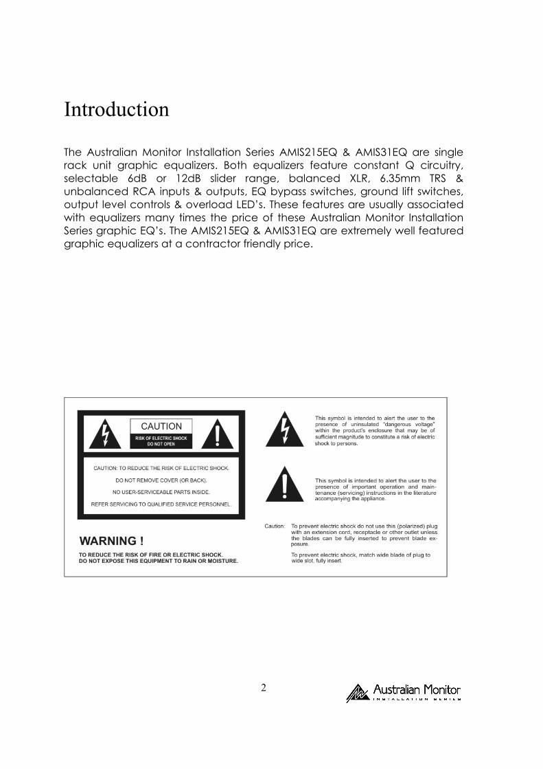
Introduction The Australian Monitor Installation Series AMIS215EQ & AMIS31EQ are single rack unit graphic equalizers. Both equalizers feature constant Q circuitry, selectable 6dB or 12dB slider range, balanced XLR, 6.35mm TRS & unbalanced RCA inputs & outputs, EQ bypass switches, ground lift switches, output level controls & overload LED’s. These features are usually associated with equalizers many times the price of these Australian Monitor Installation Series graphic EQ’s. The AMIS215EQ & AMIS31EQ are extremely well featured graphic equalizers at a contractor friendly price.
3
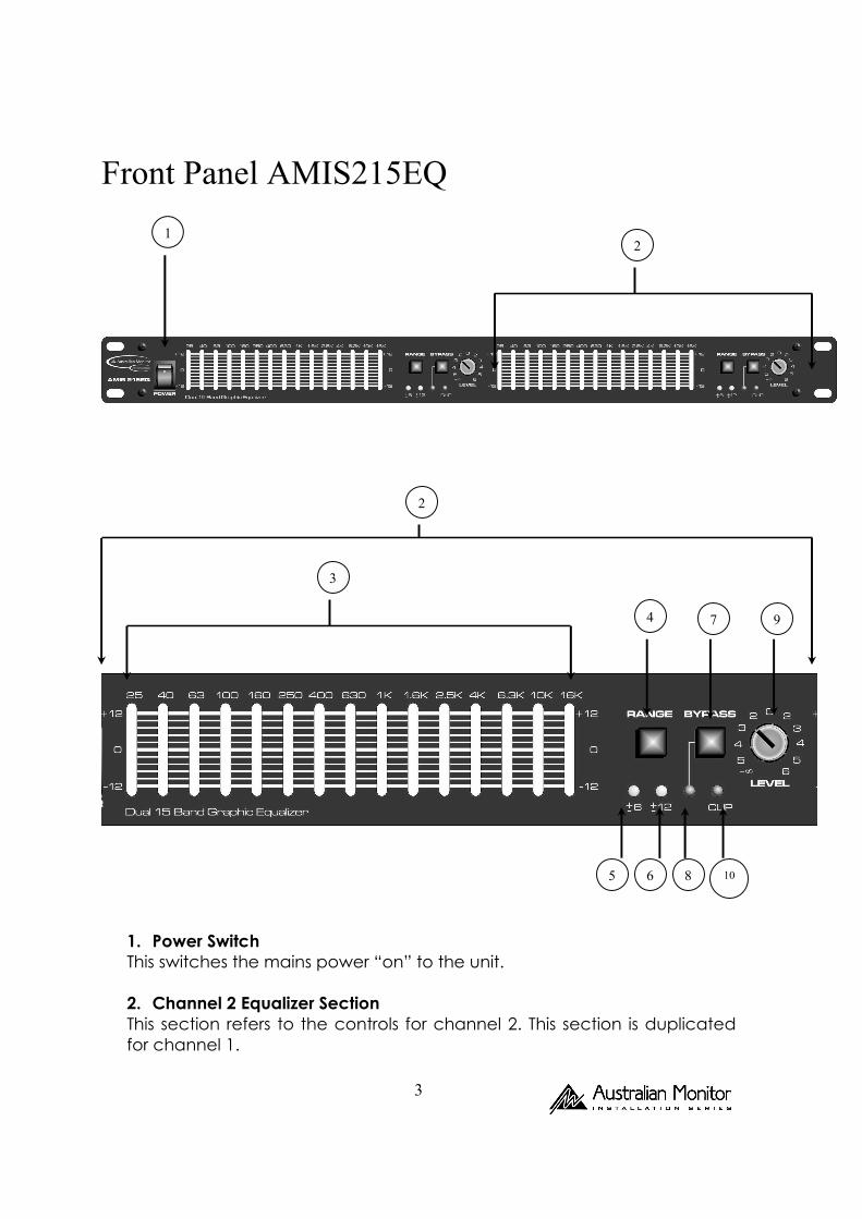
Front Panel AMIS215EQ
1. Power Switch This switches the mains power “on” to the unit. 2. Channel 2 Equalizer Section This section refers to the controls for channel 2. This section is duplicated for channel 1.
1 2
4
5 6
7
8
9
10
3
2
4
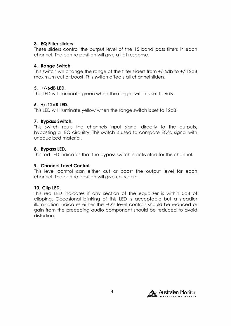
3. EQ Filter sliders These sliders control the output level of the 15 band pass filters in each channel. The centre position will give a flat response. 4. Range Switch. This switch will change the range of the filter sliders from +/-6db to +/-12dB maximum cut or boost. This switch affects all channel sliders. 5. +/-6dB LED. This LED will illuminate green when the range switch is set to 6dB. 6. +/-12dB LED. This LED will illuminate yellow when the range switch is set to 12dB. 7. Bypass Switch. This switch routs the channels input signal directly to the outputs, bypassing all EQ circuitry. This switch is used to compare EQ’d signal with unequalized material. 8. Bypass LED. This red LED indicates that the bypass switch is activated for this channel. 9. Channel Level Control This level control can either cut or boost the output level for each channel. The centre position will give unity gain. 10. Clip LED. This red LED indicates if any section of the equalizer is within 5dB of clipping. Occasional blinking of this LED is acceptable but a steadier illumination indicates either the EQ’s level controls should be reduced or gain from the preceding audio component should be reduced to avoid distortion.
5
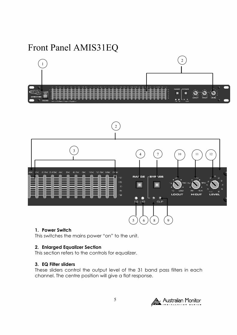
Front Panel AMIS31EQ
1. Power Switch This switches the mains power “on” to the unit. 2. Enlarged Equalizer Section This section refers to the controls for equalizer. 3. EQ Filter sliders These sliders control the output level of the 31 band pass filters in each channel. The centre position will give a flat response.
1 2
2
3 4 7
5 6 8
10 11 12
9
6
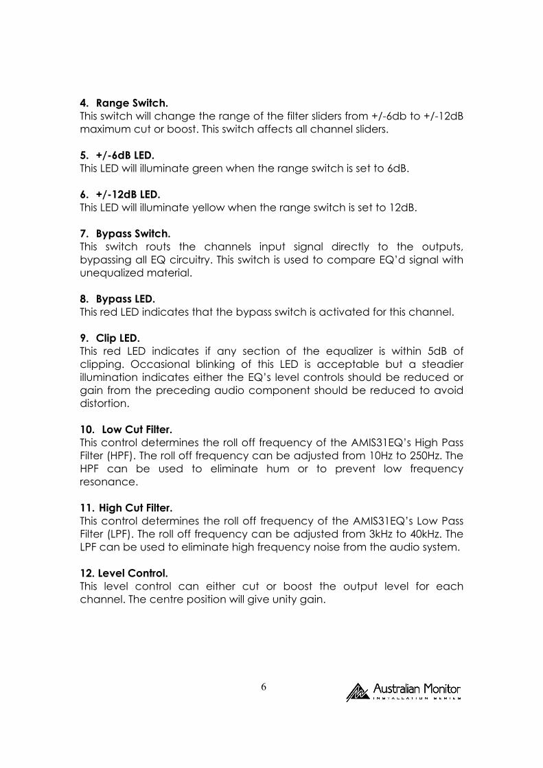
4. Range Switch. This switch will change the range of the filter sliders from +/-6db to +/-12dB maximum cut or boost. This switch affects all channel sliders. 5. +/-6dB LED. This LED will illuminate green when the range switch is set to 6dB. 6. +/-12dB LED. This LED will illuminate yellow when the range switch is set to 12dB. 7. Bypass Switch. This switch routs the channels input signal directly to the outputs, bypassing all EQ circuitry. This switch is used to compare EQ’d signal with unequalized material. 8. Bypass LED. This red LED indicates that the bypass switch is activated for this channel. 9. Clip LED. This red LED indicates if any section of the equalizer is within 5dB of clipping. Occasional blinking of this LED is acceptable but a steadier illumination indicates either the EQ’s level controls should be reduced or gain from the preceding audio component should be reduced to avoid distortion. 10. Low Cut Filter. This control determines the roll off frequency of the AMIS31EQ’s High Pass Filter (HPF). The roll off frequency can be adjusted from 10Hz to 250Hz. The HPF can be used to eliminate hum or to prevent low frequency resonance. 11. High Cut Filter. This control determines the roll off frequency of the AMIS31EQ’s Low Pass Filter (LPF). The roll off frequency can be adjusted from 3kHz to 40kHz. The LPF can be used to eliminate high frequency noise from the audio system. 12. Level Control. This level control can either cut or boost the output level for each channel. The centre position will give unity gain.
7
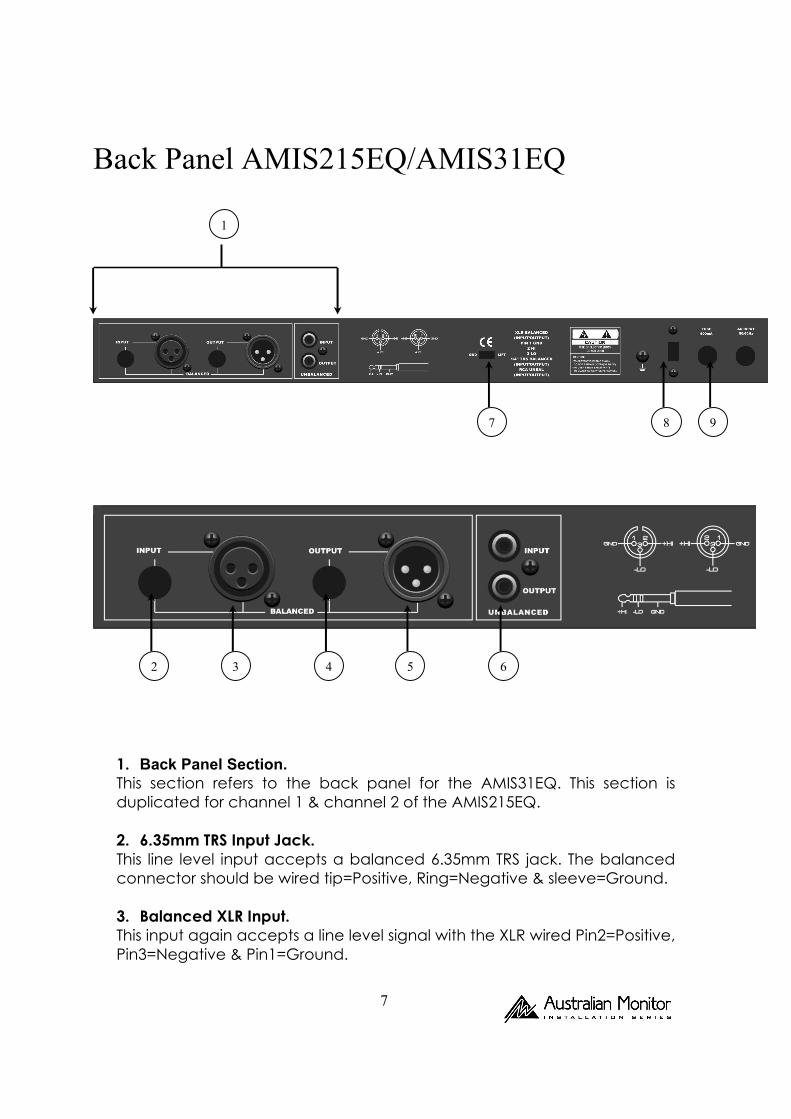
Back Panel AMIS215EQ/AMIS31EQ
1. Back Panel Section. This section refers to the back panel for the AMIS31EQ. This section is duplicated for channel 1 & channel 2 of the AMIS215EQ. 2. 6.35mm TRS Input Jack. This line level input accepts a balanced 6.35mm TRS jack. The balanced connector should be wired tip=Positive, Ring=Negative & sleeve=Ground. 3. Balanced XLR Input. This input again accepts a line level signal with the XLR wired Pin2=Positive, Pin3=Negative & Pin1=Ground.
1
2 3 4 5 6
7 8 9
8
4. 6.35mm TRS output Jack. This is the line level output of this channel. The 6.35mm jack should be wired as point (2). 5. Balanced XLR output. This is the balanced XLR line level output of this channel. The XLR should be wired as point (3). 6. Unbalanced RCA Input/Output. These RCA Input/Outputs provide an unbalanced line level input & output. The RCA connectors should be wired Tip=Positive Sleeve=Ground. Note: Only one style of connector should be used at one time. 7. Ground Lift Switch. The ground lift switch is used to disconnect the signal earth from the mains & chassis earth. This is used to help eliminate hum caused by ground loops. 8. Mains Voltage Selector. This switches mains voltage from 230VAC to 240VAC. Please ensure that this switch is set to the correct voltage for your part of the world. 9. Fuse Holder. Both the AMIS215EQ & AMIS31EQ have a 500mA mains voltage fuse.
Set Up & Operation.
Graphic equalizers are used to modify the frequency contour of a sound system. The graphic equalizer provides a solution to a number of problems that can be posed by any acoustically challenging environment. The AMIS series of graphic equalizers are designed to accept a line level signal from a mixer, professional processor or insert point of an AMIS series amplifier. The following is a quick set up guide for the AMIS215EQ & AMIS31EQ. 1. Set the EQ level controls to the centre detent 0dB position.
2. Select the Bypass switch to the “on” position (red LED illuminated).
9
3. Set all slider controls to the centre detent 0dB position.
4. Set the range switch to the 6dB position (green LED illuminated).
5. Apply signal to the audio system.
6. Release the bypass switch (red LED off)
7. If the overload LED illuminates you may need to turn the level control down until the LED flashes occasionally or is off.
8. Equalize your audio system as desired.
9. If there is not enough adjustment available to achieve the equalization
required, you may need to go back to step 2 & repeat the equalization process with the range switch in the 12dB position (yellow LED illuminated).
AMIS215EQ/AMIS31EQ Specifications 1. Equalizer
Bands; AMIS215EQ; 2 x 15 2/3 Octave ISO Spacing from 20Hz – 20kHz AMIS31EQ; 31 1/3 Octave ISO Spacing from 20Hz - 20kHz Type; Constant Q Accuracy; 3% Centre Frequency Travel; 20mm Positive Centre Detent Range; +/- 6dB or +/- 12dB selectable 2. Inputs Type; Active balanced/unbalanced Connectors; 3 pin XLR, 6.35mm TRS balanced, RCA unbalanced Impedance; 20k Ohms balanced, 15k Ohms unbalanced Max level; +22dBm (level control at centre)
10
3. Outputs Type; Active balanced/unbalanced Connectors; 3 pin XLR, 6.35mm TRS balanced, RCA unbalanced Impedance; <150 Ohms Typical Max Level; +22dbm (2k ohms) +18dBm (600 ohms) 4. Rfi Filters; Yes 5. Passive Bypass Switches; Yes 6. Overload LED Switches; 5dB below clipping 7. Low Cut Filter; 10-250Hz, 12dB per octave 8. High Cut Filter; 3kHz-40kHz, 12dB per octave 9. Frequency Response; 20Hz-20kHz 10. IM Distortion (SMPTE); 0.005% 11. Signal to Noise Ratio; -94dB (20kHz noise bandwidth) 12. Channel Separation; 50dB 13. Common Mode Rejection; 50:1
14. Voltage; 190-250VAC, 50Hz 15. Dimensions; 44.5mm (h) x 483mm (w) x 216mm (d) 16. Weight; 2.5kg

11
Notes

12


![Constant-Q Graphic Equalizers* - Rane · · 2016-08-24band octave equalizer. ... a detailed discussion of a typical gyrator graphic equalizer, see [8]; for a circuit critique of](https://img.pdfslide.net/doc/110x75/5ae4f0f37f8b9a90138fb0fa/constant-q-graphic-equalizers-octave-equalizer-a-detailed-discussion-of.jpg)