Embed Size (px)
Citation preview
D E S C R I P T I O N
POK
BIPOK
QUADRIPOK
TRIPOK
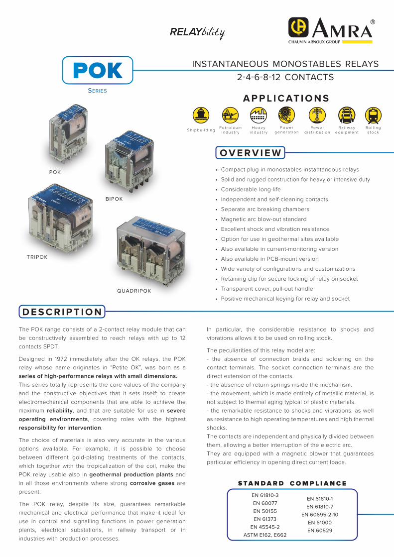
• Compact plug-in monostables instantaneous relays
• Solid and rugged construction for heavy or intensive duty
• Considerable long-life
• Independent and self-cleaning contacts
• Separate arc breaking chambers
• Magnetic arc blow-out standard
• Excellent shock and vibration resistance
• Option for use in geothermal sites available
• Also available in current-monitoring version
• Also available in PCB-mount version
• Wide variety of configurations and customizations
• Retaining clip for secure locking of relay on socket
• Transparent cover, pull-out handle
• Positive mechanical keying for relay and socket
O V E R V I E W
The POK range consists of a 2-contact relay module that can be constructively assembled to reach relays with up to 12 contacts SPDT.
Designed in 1972 immediately after the OK relays, the POK relay whose name originates in “Petite OK”, was born as a series of high-performance relays with small dimensions.This series totally represents the core values of the company and the constructive objectives that it sets itself: to create electromechanical components that are able to achieve the maximum reliability, and that are suitable for use in severe operating environments, covering roles with the highest responsibility for intervention.
The choice of materials is also very accurate in the various options available. For example, it is possible to choose between different gold-plating treatments of the contacts, which together with the tropicalization of the coil, make the POK relay usable also in geothermal production plants and in all those environments where strong corrosive gases are present.
The POK relay, despite its size, guarantees remarkable mechanical and electrical performance that make it ideal for use in control and signalling functions in power generation plants, electrical substations, in railway transport or in industries with production processes.
In particular, the considerable resistance to shocks and vibrations allows it to be used on rolling stock.
The peculiarities of this relay model are:- the absence of connection braids and soldering on the contact terminals. The socket connection terminals are the direct extension of the contacts.- the absence of return springs inside the mechanism.- the movement, which is made entirely of metallic material, is not subject to thermal aging typical of plastic materials.- the remarkable resistance to shocks and vibrations, as well as resistance to high operating temperatures and high thermal shocks.The contacts are independent and physically divided between them, allowing a better interruption of the electric arc.They are equipped with a magnetic blower that guarantees particular efficiency in opening direct current loads.
COMP L I ANC ESTANDARD
EN 61810-3
EN 60077
EN 50155
EN 61373
EN 45545-2
ASTM E162, E662
EN 61810-1
EN 61810-7
EN 60695-2-10
EN 61000
EN 60529
INSTANTANEOUS MONOSTABLES RELAYS2-4-6-8-12 CONTACTS
SERIES
POK
S h i p b u i l d i n gH e a v y
i n d u s t r yR a i l w a y
e q u i p m e n tRo l l i n gs t o c k
P o w e rg e n e r a t i o n
P e t r o l e u mi n d u s t r y
A P P L I C AT I O N S
P o w e rd i s t r i b u t i o n
Page 2 / 8
1. On all contacts simultaneously, reduction of 30%.
2. The max. peak and pulse currents are those currents that can be handled, for a specified time, by the contact. They do not refer to steady or interrupted currents.
3. For other values, see electrical life expectancy curves.
4. Values referred to a new product, measured in laboratory. The ability to maintain this performance over the time depends on the environmental conditions and the contact’ frequency use.
The use of gold plated contacts is recommended in the case of very low loads.
5. Specifications of contacts on new relay
a. Plating material: P4GEO: gold-nickel alloy (>6µ) P8: gold-cobalt alloy (>5µ), knurled contact
b. When the gold-plated contact is subject to heavy loads, it will be degraded on the surface. In this case, the characteristics of the standard contact should be taken into consideration.
This does not impair relay operation.
6. Unless specified otherwise, the operating time signifies until stabilization of the contact (including bounces).
7. Addition of a flyback diode connected in parallel with the coil (DC version only) causes an increase in operating time when the relay drops out.
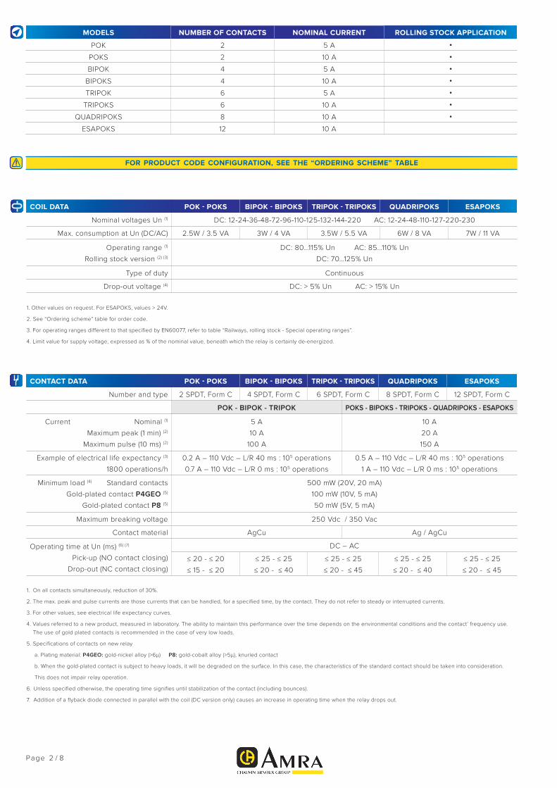
MODELS NUMBER OF CONTACTS NOMINAL CURRENT ROLLING STOCK APPLICATION
POK 2 5 A •
POKS 2 10 A •
BIPOK 4 5 A •
BIPOKS 4 10 A •
TRIPOK 6 5 A •
TRIPOKS 6 10 A •
QUADRIPOKS 8 10 A •
ESAPOKS 12 10 A
FOR PRODUCT CODE CONFIGURATION, SEE THE “ORDERING SCHEME” TABLE
COIL DATA POK - POKS BIPOK - BIPOKS TRIPOK - TRIPOKS QUADRIPOKS ESAPOKS
Nominal voltages Un (1) DC: 12-24-36-48-72-96-110-125-132-144-220 AC: 12-24-48-110-127-220-230
Max. consumption at Un (DC/AC) 2.5W / 3.5 VA 3W / 4 VA 3.5W / 5.5 VA 6W / 8 VA 7W / 11 VA
Operating range (1)
Rolling stock version (2) (3)
DC: 80…115% Un AC: 85…110% Un
DC: 70…125% Un
Type of duty Continuous
Drop-out voltage (4) DC: > 5% Un AC: > 15% Un
1. Other values on request. For ESAPOKS, values > 24V.
2. See “Ordering scheme” table for order code.
3. For operating ranges different to that specified by EN60077, refer to table “Railways, rolling stock - Special operating ranges”.
4. Limit value for supply voltage, expressed as % of the nominal value, beneath which the relay is certainly de-energized.
CONTACT DATA POK - POKS BIPOK - BIPOKS TRIPOK - TRIPOKS QUADRIPOKS ESAPOKS
Number and type 2 SPDT, Form C 4 SPDT, Form C 6 SPDT, Form C 8 SPDT, Form C 12 SPDT, Form C
POK - BIPOK - TRIPOK POKS - BIPOKS - TRIPOKS - QUADRIPOKS - ESAPOKS
Current Nominal (1)
Maximum peak (1 min) (2)
Maximum pulse (10 ms) (2)
5 A
10 A
100 A
10 A
20 A
150 A
Example of electrical life expectancy (3)
1800 operations/h
0.2 A – 110 Vdc – L/R 40 ms : 105 operations
0.7 A – 110 Vdc – L/R 0 ms : 105 operations
0.5 A – 110 Vdc – L/R 40 ms : 105 operations
1 A – 110 Vdc – L/R 0 ms : 105 operations
Minimum load (4) Standard contacts
Gold-plated contact P4GEO (5)
Gold-plated contact P8 (5)
500 mW (20V, 20 mA)
100 mW (10V, 5 mA)
50 mW (5V, 5 mA)
Maximum breaking voltage 250 Vdc / 350 Vac
Contact material AgCu Ag / AgCu
Operating time at Un (ms) (6) (7)
Pick-up (NO contact closing)
Drop-out (NC contact closing)
DC – AC
≤ 20 - ≤ 20
≤ 15 - ≤ 20
≤ 25 - ≤ 25
≤ 20 - ≤ 40
≤ 25 - ≤ 25
≤ 20 - ≤ 45
≤ 25 - ≤ 25
≤ 20 - ≤ 40
≤ 25 - ≤ 25
≤ 20 - ≤ 45
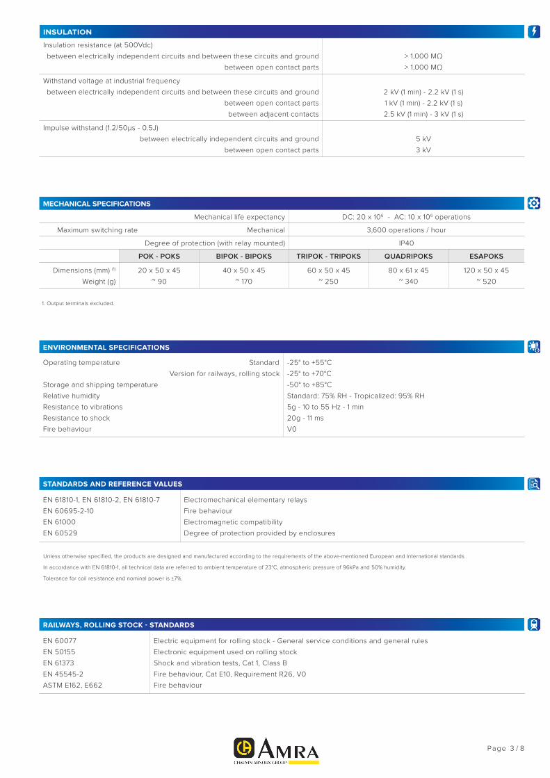
INSULATION
Insulation resistance (at 500Vdc)
between electrically independent circuits and between these circuits and ground
between open contact parts
> 1,000 MΩ
> 1,000 MΩ
Withstand voltage at industrial frequency
between electrically independent circuits and between these circuits and ground
between open contact parts
between adjacent contacts
2 kV (1 min) - 2.2 kV (1 s)
1 kV (1 min) - 2.2 kV (1 s)
2.5 kV (1 min) - 3 kV (1 s)
Impulse withstand (1.2/50μs - 0.5J)
between electrically independent circuits and ground
between open contact parts
5 kV
3 kV
MECHANICAL SPECIFICATIONS
Mechanical life expectancy DC: 20 x 106 - AC: 10 x 106 operations
Maximum switching rate Mechanical 3,600 operations / hour
Degree of protection (with relay mounted) IP40
POK - POKS BIPOK - BIPOKS TRIPOK - TRIPOKS QUADRIPOKS ESAPOKS
Dimensions (mm) (1)
Weight (g)
20 x 50 x 45
~ 90
40 x 50 x 45
~ 170
60 x 50 x 45
~ 250
80 x 61 x 45
~ 340
120 x 50 x 45
~ 520
1. Output terminals excluded.
ENVIRONMENTAL SPECIFICATIONS
Operating temperature Standard
Version for railways, rolling stock
Storage and shipping temperature
Relative humidity
Resistance to vibrations
Resistance to shock
Fire behaviour
-25° to +55°C
-25° to +70°C
-50° to +85°C
Standard: 75% RH - Tropicalized: 95% RH
5g - 10 to 55 Hz - 1 min
20g - 11 ms
V0
STANDARDS AND REFERENCE VALUES
EN 61810-1, EN 61810-2, EN 61810-7
EN 60695-2-10
EN 61000
EN 60529
Electromechanical elementary relays
Fire behaviour
Electromagnetic compatibility
Degree of protection provided by enclosures
Unless otherwise specified, the products are designed and manufactured according to the requirements of the above-mentioned European and International standards.
In accordance with EN 61810-1, all technical data are referred to ambient temperature of 23°C, atmospheric pressure of 96kPa and 50% humidity.
Tolerance for coil resistance and nominal power is ±7%.
RAILWAYS, ROLLING STOCK - STANDARDS
EN 60077
EN 50155
EN 61373
EN 45545-2
ASTM E162, E662
Electric equipment for rolling stock - General service conditions and general rules
Electronic equipment used on rolling stock
Shock and vibration tests, Cat 1, Class B
Fire behaviour, Cat E10, Requirement R26, V0
Fire behaviour
Page 3 / 8

Page 4 / 8
RAILWAYS, ROLLING STOCK - SPECIAL OPERATING RANGES FOR POK(S) - BIPOK(S) RELAYS (1)
Nominal voltage Minimum pick-up voltage Maximum operating voltage Order symbol (1)
24 Vdc 18 33 Z01
24 Vdc 16 32 Z02
24 Vdc 16.8 32 Z03
24 Vdc 19 30 Z04
36 Vdc 28 46 Z01
72 Vdc 55 104 Z01
72 Vdc 55 96 Z02
110 Vdc 77 144 Z01
(1) To order the relay with the special operating range, indicate the “Z0x” symbol in the “Keying position” field of the ordering scheme.
The special range may be subject to operating specifications different from standard specifications. Please contact us for further information.
CONFIGURATION - OPTIONS
P2
Tropicalization of the coil with epoxy resin for use with 95% RH (@ T 50 °C). This treatment also protects the coil
against corrosion which could occur by combination of the humidity with certain chemical agents, such as those
found in acid atmospheres (typical of geothermal power stations) or saline atmospheres.
P4GEO
Gold plating of contacts with gold-nickel alloy, thickness ≥ 6μ. This treatment ensures long-term capacity of the
contact to conduct lower currents in harsh ambient conditions such as acid atmospheres (typical of geothermal
power stations) or saline atmospheres.
P5GEO P4GEO gold-plating of contacts + P2 coil tropicalization.
P6GEO P4GEO type gold-plating, but applied to contacts, contact terminals and output terminals + P2 coil tropicalization.
P7 AgCdO (silver cadmium oxide) contacts.
P8Gold plating of contacts with gold-cobalt alloy, thickness ≥ 5μ, knurled fixed contact. This finish allows further
improvement of the performance provided by gold-plated contact, compared to P4GEO treatment.
LED LED indicator showing presence of power supply, wired in parallel with the coil.
FLYBACK DIODE Polarized component connected in parallel with the coil (type 1N4007 or BYW56 for rolling stock version) designed
to suppress overvoltages generated by the coil when de-energized.
VARISTORNon-polarized component connected in parallel with the coil, designed to suppress overvoltages higher than the
clamping voltage, generated by the coil when de-energized.
TRANSILNon-polarized component connected in parallel with the coil. Behaviour is similar to that of a varistor, with faster
operating times.
LOW TEMPERATURE Minimum operating temperature -50°C, only for rolling stock version (option “L”).
C.S. PCB-mount version (for POK-POKS-BIPOK-BIPOKS only).
Page 5 / 8
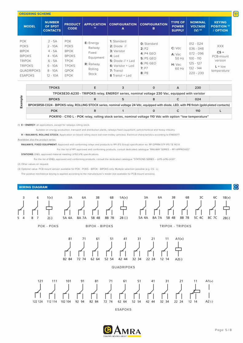
ORDERING SCHEME
MODELNUMBER OF SPDT
CONTACTS
PRODUCT CODE
APPLICATION (1)
CONFIGURATIONA
CONFIGURATIONB
TYPE OF POWER SUPPLY
NOMINALVOLTAGE
(V) (2)
KEYINGPOSITION (3)
/ OPTION
POK
POKS
BIPOK
BIPOKS
TRIPOK
TRIPOKS
QUADRIPOKS
ESAPOKS
2 - 5A
2 - 10A
4 - 5A
4 - 10A
6 - 5A
6 - 10A
8 - 10A
12 - 10A
POK
POKS
BPOK
BPOKS
TPOK
TPOKS
QPOK
EPOK
E: Energy
Railway
Fixed
Equipment
R: Railway
Rolling
Stock
1: Standard
2: Diode //
3: Varistor
4: Led
5: Diode // + Led
6: Varistor + Led
7: Transil
8 Transil + Led
0: Standard
2: P2
4: P4 GEO
5: P5 GEO
6: P6 GEO
7: P7
8: P8
C: Vdc
A: Vac 50 Hz
H: Vac 60 Hz
012 - 024
036 - 048
072 - 096
100 - 110
125 - 127
132 - 144
220 - 230
XXX
CS = PCB-mount
version
L = low temperature
(1) E = ENERGY: all applications, except for railways rolling stock.
Suitable on energy production, transport and distribution plants, railways fixed equipment, petrolchemical and heavy industry.
R = RAILWAYS, ROLLING STOCK: Application on board rolling stock (rail-tram-trolley vehicles). Electrical characteristics according to EN60077.
Availables also the product series:
RAILWAYS, FIXED EQUIPMENT: Approved and conforming relays and products to RFI (FS Group) specification no. RFI DPRIM STF IFS TE 143 A
For the list of RFI approved and conforming products, consult dedicated catalogue “RAILWAY SERIES – RFI APPROVED”.
STATIONS: ENEL approved material meeting LV15/LV16 specifications.
For the list of ENEL approved and conforming products, consult the dedicated catalogue “STATIONS SERIES – LV15-LV16-LV20”.
(2) Other values on request.
(3) Optional value. PCB-mount version available for POK - POKS - BIPOK - BIPOKS only. Multiple selection possible (e.g. CS - L).
The positive mechanical keying is applied according to the manufacturer’s model (not available for PCB-mount versions).
TPOKS E 3 0 A 230
TPOKSE30-A230 - TRIPOKS relay, ENERGY series, nominal voltage 230 Vac, equipped with varistor
BPOKS R 5 8 C 024
BPOKSR58-C024 - BIPOKS relay, ROLLING STOCK series, nominal voltage 24 Vdc, equipped with diode, LED, with P8 finish (gold-plated contacts)
POK R 1 0 C 110 L
POKR10 - C110 L - POK relay, rolling stock series, nominal voltage 110 Vdc with option “low temperature”
Exa
mp
le
+WIRING DIAGRAM
BIPOK - BIPOKS
QUADRIPOKS
POK - POKS TRIPOK - TRIPOKS
ESAPOKS
Page 6 / 8
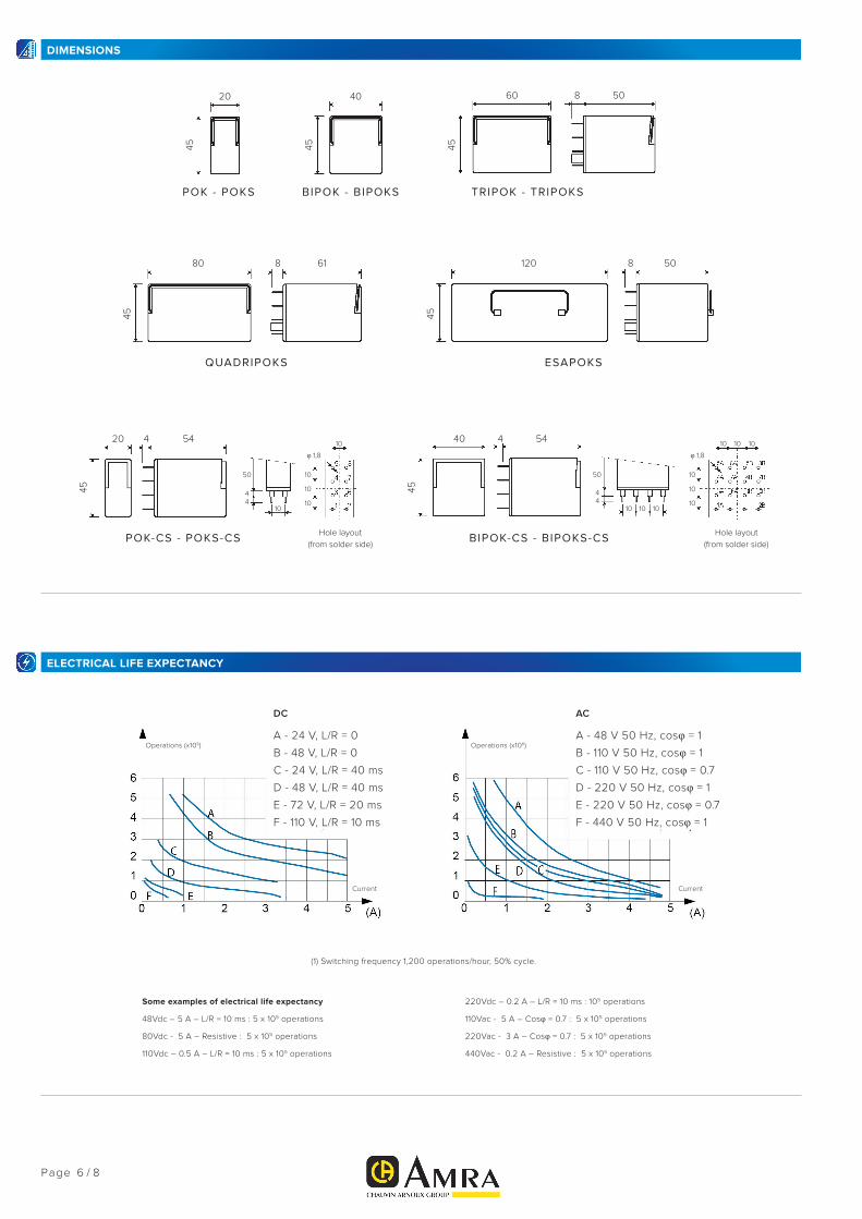
DIMENSIONS
QUADRIPOKS ESAPOKS
45 45
80 61 120 8 508
POK - POKS BIPOK - BIPOKS TRIPOK - TRIPOKS45 45 45
20 40 60 508
POK-CS - POKS-CS Hole layout(from solder side)
Hole layout(from solder side)
BIPOK-CS - BIPOKS-CS
45
4 44 4
50 50
10 10 10 10
10 10 10 10
10 10
φ 1,8 φ 1,8
10 10
10 10
5440
45
5420 4 4
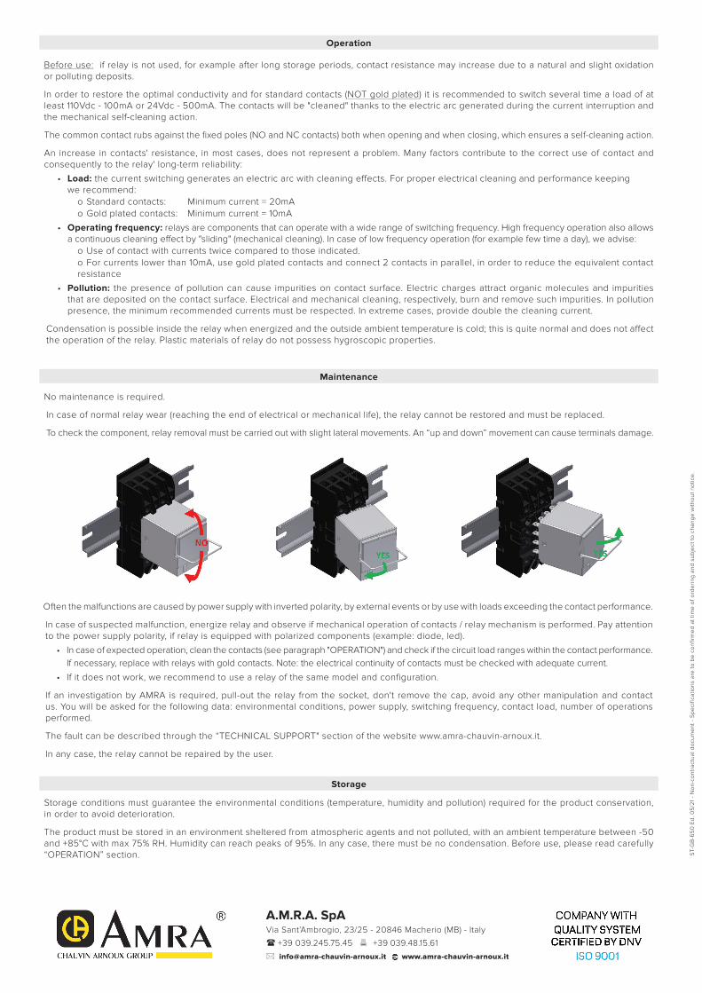
ELECTRICAL LIFE EXPECTANCY
Some examples of electrical life expectancy
48Vdc – 5 A – L/R = 10 ms : 5 x 10⁵ operations
80Vdc - 5 A – Resistive : 5 x 10⁵ operations
110Vdc – 0.5 A – L/R = 10 ms : 5 x 10⁵ operations
220Vdc – 0.2 A – L/R = 10 ms : 105 operations
110Vac - 5 A – Cosφ = 0.7 : 5 x 10⁵ operations
220Vac - 3 A – Cosφ = 0.7 : 5 x 10⁵ operations
440Vac - 0.2 A – Resistive : 5 x 10⁵ operations
DC
A - 24 V, L/R = 0
B - 48 V, L/R = 0
C - 24 V, L/R = 40 ms
D - 48 V, L/R = 40 ms
E - 72 V, L/R = 20 ms
F - 110 V, L/R = 10 ms
A - 48 V 50 Hz, cosφ = 1
B - 110 V 50 Hz, cosφ = 1
C - 110 V 50 Hz, cosφ = 0.7
D - 220 V 50 Hz, cosφ = 1
E - 220 V 50 Hz, cosφ = 0.7
F - 440 V 50 Hz, cosφ = 1
AC
(1) Switching frequency 1,200 operations/hour, 50% cycle.
Operations (x106)
Current Current
Operations (x106)

SOCKETS POK - POKS BIPOK - BIPOKS TRIPOK - TRIPOKS QUADRIPOKS ESAPOKS
Number of terminals 8 16 24 32 48
For wall or rail mounting
Spring clamp, wall or DIN H35 rail mounting PAIR080 PAIR160 PAIR240 PAIR320 PAIR480
Screw, wall or DIN H35 rail mounting 50IP20-I DIN 48BIP20-I DIN 78BIP20-I DIN 96IP20-I DIN 156IP20-I DIN
Screw, wall mounting 50L 48BL 78BL 96BL 156BL
For flush mounting
Spring clamp PRIR080 PRIR160 PRIR240 PRIR320 PRIR480
Double faston (4.8 x 0.8 mm) ADF1 ADF2 ADF3 ADF4 ADF6
Screw 53IL 43IL 73IL - -
For mounting on PCB
65 (1) 65 - - -
(1) Suitable for mounting 2 relays side by side.
RETAINING CLIPS (correspondence with sockets) POK - POKS BIPOK - BIPOKS TRIPOK - TRIPOKS QUADRIPOKS ESAPOKS
Number of clips per relay 1 1 (1) 2 2 2
SOCKET MODEL CLIP MODEL
For wall or rail mounting
PAIR080, PAIR160, PAIR240, PAIR320, PAIR480 RPB48 RPB48 RPB48 RQ48 RPB48
50IP20-I DIN, 48BIP20-I DIN, 78BIP20-I DIN,
96IP20-I DIN, 56IP20-I DINRPB48 RPB48 RPB48 RQ48 RPB48
50L, 48BL, 78BL, 96BL, 156BL RPB48 RPB48 RPB48 RQ48 RPB48
For flush mounting
PRIR080, PRIR160, PRIR240, PRIR320, PRIR480 RPB48 RPB48 RPB48 RQ48 RPB48
ADF1, ADF2, ADF3, ADF4, ADF6 RPB48 RPB48 RPB48 RQ48 RPB48
ADF, 53IL, 43IL, 73IL (2) RPB43 RPB43 RPB43 - -
For mounting on PCB
65 RPB43 RPB43 - - -
(1) Assume two clips for use on rolling stock.
(2) Insert the clip before fastening the socket on the panel.
Page 7 / 8
INSTALLATION, OPERATION AND MAINTENANCE
Installation
Before installing the relay on a wired socket, disconnect the power supply.
The preferential mounting position is on the wall, with the relay positioned horizontally in the “reading orienting” of marking so that the label is readable in the correct sense.
Spacing: the distance between adjacent relays depends on use' conditions.
If a relay is used in the "less favorable" conditions that occur with "simultaneously":
• Power supply: the maximum allowed, permanently
• Ambient temperature: the maximum allowed, permanently
• Current on the contacts: the maximum allowed, permanently
• Number of contacts used: 100%it is strongly recommended to space relay at least 5 mm horizontally and 20 mm vertically, to allow for proper upward heat' dissipation andincrease the longevity of the component.
Actually, relays could be used in less severe conditions. In this case, the distance between adjacent relays can be reduced or abolished.A correct interpretation of the use' conditions allows the optimization of the available spaces. Contact AMRA for more information.
To increase relay' longevity, we recommend mounting relays intended for “continuous use” (permanent power supply), alternating them with relays intended for less frequent use.
For a safe use, the retaining clip is recommended.
For use on rolling stock, relays have been tested to EN 61373 standard equipped with retaining clip(s).
ST-
GB
-65
0 E
d. 0
5/2
1 -
No
n-co
ntra
ctua
l do
cum
ent
- S
pe
cific
atio
ns a
re to
be
co
nfirm
ed
at t
ime
of o
rde
ring
and
sub
ject
to c
hang
e w
itho
ut n
otic
e.
A.M.R.A. SpAVia Sant’Ambrogio, 23/25 - 20846 Macherio (MB) - Italy
( +39 039.245.75.45 6 +39 039.48.15.61
* [email protected] www.amra-chauvin-arnoux.it
Operation
Before use: if relay is not used, for example after long storage periods, contact resistance may increase due to a natural and slight oxidation or polluting deposits.
In order to restore the optimal conductivity and for standard contacts (NOT gold plated) it is recommended to switch several time a load of at least 110Vdc - 100mA or 24Vdc - 500mA. The contacts will be "cleaned" thanks to the electric arc generated during the current interruption and the mechanical self-cleaning action.
The common contact rubs against the fixed poles (NO and NC contacts) both when opening and when closing, which ensures a self-cleaning action.
An increase in contacts' resistance, in most cases, does not represent a problem. Many factors contribute to the correct use of contact and consequently to the relay' long-term reliability:
• Load: the current switching generates an electric arc with cleaning effects. For proper electrical cleaning and performance keepingwe recommend:
o Standard contacts: Minimum current = 20mAo Gold plated contacts: Minimum current = 10mA
• Operating frequency: relays are components that can operate with a wide range of switching frequency. High frequency operation also allows a continuous cleaning effect by "sliding" (mechanical cleaning). In case of low frequency operation (for example few time a day), we advise:
o Use of contact with currents twice compared to those indicated.o For currents lower than 10mA, use gold plated contacts and connect 2 contacts in parallel, in order to reduce the equivalent contact resistance
• Pollution: the presence of pollution can cause impurities on contact surface. Electric charges attract organic molecules and impurities that are deposited on the contact surface. Electrical and mechanical cleaning, respectively, burn and remove such impurities. In pollution presence, the minimum recommended currents must be respected. In extreme cases, provide double the cleaning current.
Condensation is possible inside the relay when energized and the outside ambient temperature is cold; this is quite normal and does not affect the operation of the relay. Plastic materials of relay do not possess hygroscopic properties.
Maintenance
No maintenance is required.
In case of normal relay wear (reaching the end of electrical or mechanical life), the relay cannot be restored and must be replaced.
To check the component, relay removal must be carried out with slight lateral movements. An “up and down” movement can cause terminals damage.
Often the malfunctions are caused by power supply with inverted polarity, by external events or by use with loads exceeding the contact performance.
In case of suspected malfunction, energize relay and observe if mechanical operation of contacts / relay mechanism is performed. Pay attention to the power supply polarity, if relay is equipped with polarized components (example: diode, led).
• In case of expected operation, clean the contacts (see paragraph "OPERATION") and check if the circuit load ranges within the contact performance. If necessary, replace with relays with gold contacts. Note: the electrical continuity of contacts must be checked with adequate current.
• If it does not work, we recommend to use a relay of the same model and configuration.
If an investigation by AMRA is required, pull-out the relay from the socket, don't remove the cap, avoid any other manipulation and contact us. You will be asked for the following data: environmental conditions, power supply, switching frequency, contact load, number of operations performed.
The fault can be described through the “TECHNICAL SUPPORT" section of the website www.amra-chauvin-arnoux.it.
In any case, the relay cannot be repaired by the user.
Storage
Storage conditions must guarantee the environmental conditions (temperature, humidity and pollution) required for the product conservation, in order to avoid deterioration.
The product must be stored in an environment sheltered from atmospheric agents and not polluted, with an ambient temperature between -50 and +85°C with max 75% RH. Humidity can reach peaks of 95%. In any case, there must be no condensation. Before use, please read carefully “OPERATION” section.