Embed Size (px)
Citation preview
i
Copyright
© 2012 Amroad Technology Inc. All Rights Reserved. No part of this publication may be reproduced, transmitted, transcribed, stored in a retrieval system or translated into any
language in any form or by any means without the express written permission of r Technology Inc. To obtain consent, write to the attention of
Amroad Technology Inc.
Document No. DP101/R 2012-1224 V1.0
www.amroad.com.tw
DISCLAIMER Amroad reserves the right to change product specification without prior notice.
Changes may be made to the information in this publication without obligation to notify. Amroad shall not be liable for technical or editorial errors
contained herein.
TRADE MARKS Amroad logo is copyright of Amroad Technology Inc. All other products, services or trade marks mentioned in this document are the property of
their respective owners, companies or organizations.
CONTENTS
ii
Contents COPYRIGHT.............................................................................................................................................................................................................................................................I CONTENTS ............................................................................................................................................................................................................................................................II
CHAPTER 1: INTRODUCTION .......................................................................................................................................................................................................................................1
WELCOME .............................................................................................................................................................................................................................................................1 GENERAL APPLICATION OF DOOR ENTRY SYSTEM ......................................................................................................................................................................................................3 USE OF SIP ............................................................................................................................................................................................................................................................5
CHAPTER 2 : KNOWING VIDEO DOOR PHONE..........................................................................................................................................................................................................6
PACKAGE CONTENTS ..............................................................................................................................................................................................................................................6 FRONT PANEL ........................................................................................................................................................................................................................................................7 LED INDICATORS ...................................................................................................................................................................................................................................................8 REAR PANEL ........................................................................................................................................................................................................................................................10 DIMENSIONS........................................................................................................................................................................................................................................................11
CHAPTER 3 : INSTALLING VIDEO DOOR PHONE .....................................................................................................................................................................................................12
SUGGESTED INSTALLATION POSITIONS ....................................................................................................................................................................................................................12 LIGHTING CONDITIONS .........................................................................................................................................................................................................................................12 INSTALLING PROCEDURES......................................................................................................................................................................................................................................13
1. Screw the Back Plate on the wall. ......................................................................................................................................................................................................13 2. Connect the AC wires and Ethernet cable. ........................................................................................................................................................................................14 3. Screw the Video Door Phone with Back Plate. ...................................................................................................................................................................................15
CHAPTER 4 : CONFIGURING VIDEO DOOR PHONE ................................................................................................................................................................................................16
FINDING VIDEO DOOR PHONE ON NETWORKS ........................................................................................................................................................................................................16 ENTERING WEB USER INTERFACE ...........................................................................................................................................................................................................................17
iii
SYSTEM - BASIC SETTINGS .....................................................................................................................................................................................................................................18 System – Network Settings .......................................................................................................................................................................................................................20 System –Login Name.................................................................................................................................................................................................................................21 System Reboot...........................................................................................................................................................................................................................................21 Phone Settings – Audio .............................................................................................................................................................................................................................24
SIP SERVICES .......................................................................................................................................................................................................................................................26 ENTRANCE SETTINGS – EXTENSIONS .................................................................................................................................................................................................................28 ENTRANCE SETTINGS – GPIO ................................................................................................................................................................................................................................33 ENTRANCE SETTINGS – WIZARD ..........................................................................................................................................................................................................................35 ENTRANCE SETTINGS –RFID (OPTIONAL)...............................................................................................................................................................................................................37 UPGRADE – FIRMWARE UPDATE.............................................................................................................................................................................................................................39 CONFIGURATIONS ................................................................................................................................................................................................................................................41 AR APS ..............................................................................................................................................................................................................................................................42
CHAPTER 5 : USING VIDEO DOOR PHONE ...............................................................................................................................................................................................................43
MAKING CALLS FROM VIDEO DOOR PHONE ...........................................................................................................................................................................................................43 ANSWERING CALLS ON IP VIDEO PHONE/VIDEO INDOOR STATION ...........................................................................................................................................................................43 OPEN THE DOOR ..................................................................................................................................................................................................................................................43 COMMON CONTROLS ...........................................................................................................................................................................................................................................44 DP101R RFID CARD USAGE (OPTIONAL)...............................................................................................................................................................................................................45 ISSUE RFID MASTER CARD FIRST TIME ...................................................................................................................................................................................................................45 SCANNING RFID CARD TO OPEN DOOR .................................................................................................................................................................................................................46
CHAPTER 6 : APPLICATIONS ......................................................................................................................................................................................................................................47
FUNCTIONS PERFORMED BY THE DEVICES ................................................................................................................................................................................................................47 Electric Lock ...............................................................................................................................................................................................................................................47 Electric Strike .............................................................................................................................................................................................................................................47 Electric Strike with Open Button ...............................................................................................................................................................................................................49
iv
Electric Bolt................................................................................................................................................................................................................................................50 Electric Bolt with Open Button .................................................................................................................................................................................................................51 Lighting condition Function......................................................................................................................................................................................................................52
FUNCTIONS PERFORMED BY THE IP-PBX (COMPATIBLE WITH AMORAD IP-PBX).........................................................................................................................................................54 FCC STATEMENT........................................................................................................................................................................................................................................55 CE DECLARATION OF CONFORMITY (EUROPE)................................................................................................................................................................................56

CONTENTS
v
DP101/R MANUAL FOR SYSTEM INTEGRATOR
1
Chapter 1: Introduction Welcome
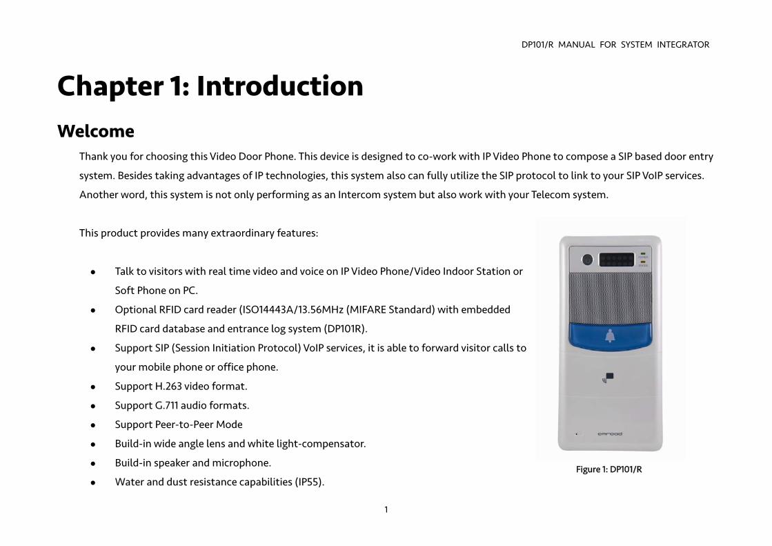
Thank you for choosing this Video Door Phone. This device is designed to co-work with IP Video Phone to compose a SIP based door entry
system. Besides taking advantages of IP technologies, this system also can fully utilize the SIP protocol to link to your SIP VoIP services.
Another word, this system is not only performing as an Intercom system but also work with your Telecom system.
This product provides many extraordinary features:
Talk to visitors with real time video and voice on IP Video Phone/Video Indoor Station or
Soft Phone on PC.
Optional RFID card reader (ISO14443A/13.56MHz (MIFARE Standard) with embedded
RFID card database and entrance log system (DP101R).
Support SIP (Session Initiation Protocol) VoIP services, it is able to forward visitor calls to
your mobile phone or office phone.
Support H.263 video format.
Support G.711 audio formats.
Support Peer-to-Peer Mode
Build-in wide angle lens and white light-compensator.
Build-in speaker and microphone.
Water and dust resistance capabilities (IP55). Figure 1: DP101/R
DP101/R MANUAL FOR SYSTEM INTEGRATOR
2
Friendly web user interface for configuration and management.
Support PoE (Power over Ethernet, 802.3af) module (External power supply AC 48V)
Please read this user guide before installing the device. Please contact your dealers or system integrators if you have questions.
DP101/R MANUAL FOR SYSTEM INTEGRATOR
3
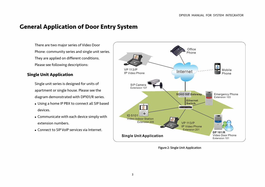
General Application of Door Entry System
There are two major series of Video Door
Phone: community series and single unit series.
They are applied on different conditions.
Please see following descriptions:
Single Unit Application
Single unit series is designed for units of
apartment or single house. Please see the
diagram demonstrated with DP101/R series.
Using a home IP PBX to connect all SIP based
devices.
Communicate with each device simply with
extension numbers.
Connect to SIP VoIP services via Internet.
Figure 2: Single Unit Application
DP101/R MANUAL FOR SYSTEM INTEGRATOR
4
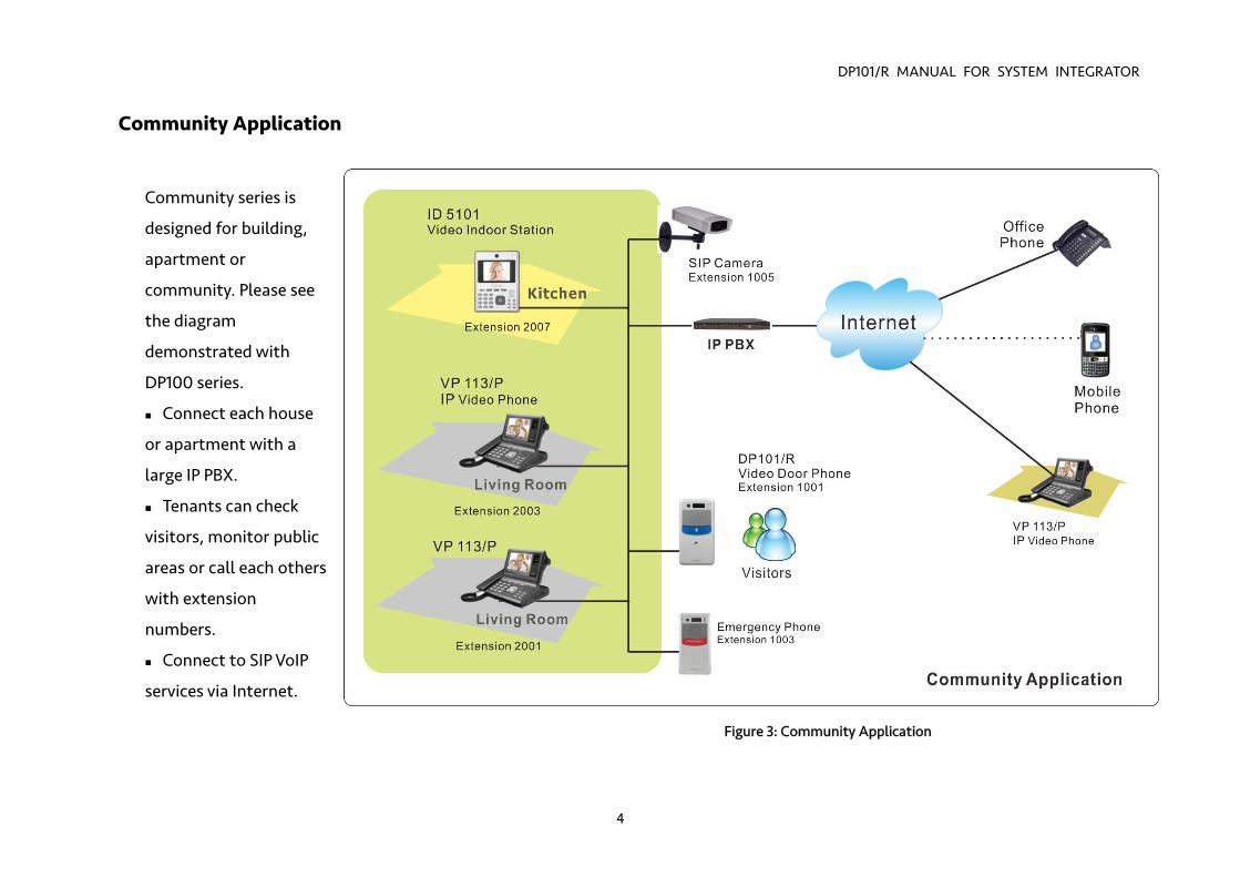
Community Application
Community series is
designed for building,
apartment or
community. Please see
the diagram
demonstrated with
DP100 series.
Connect each house
or apartment with a
large IP PBX.
Tenants can check
visitors, monitor public
areas or call each others
with extension
numbers.
Connect to SIP VoIP
services via Internet.
Figure 3: Community Application
DP101/R MANUAL FOR SYSTEM INTEGRATOR
5
Use of SIP
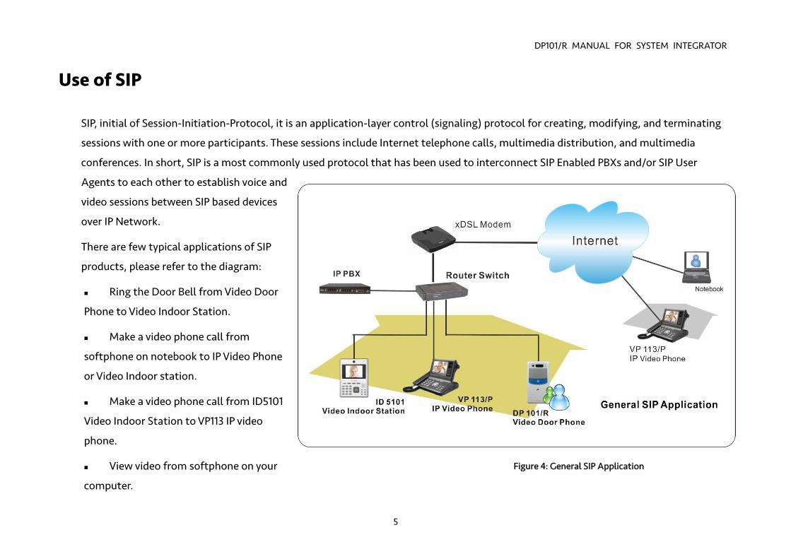
SIP, initial of Session-Initiation-Protocol, it is an application-layer control (signaling) protocol for creating, modifying, and terminating
sessions with one or more participants. These sessions include Internet telephone calls, multimedia distribution, and multimedia
conferences. In short, SIP is a most commonly used protocol that has been used to interconnect SIP Enabled PBXs and/or SIP User
Agents to each other to establish voice and
video sessions between SIP based devices
over IP Network.
There are few typical applications of SIP
products, please refer to the diagram:
Ring the Door Bell from Video Door
Phone to Video Indoor Station.
Make a video phone call from
softphone on notebook to IP Video Phone
or Video Indoor station.
Make a video phone call from ID5101
Video Indoor Station to VP113 IP video
phone.
View video from softphone on your
computer.
Figure 4: General SIP Application
DP101/R MANUALR
6
Chapter 2 : Knowing Video Door Phone Package Contents
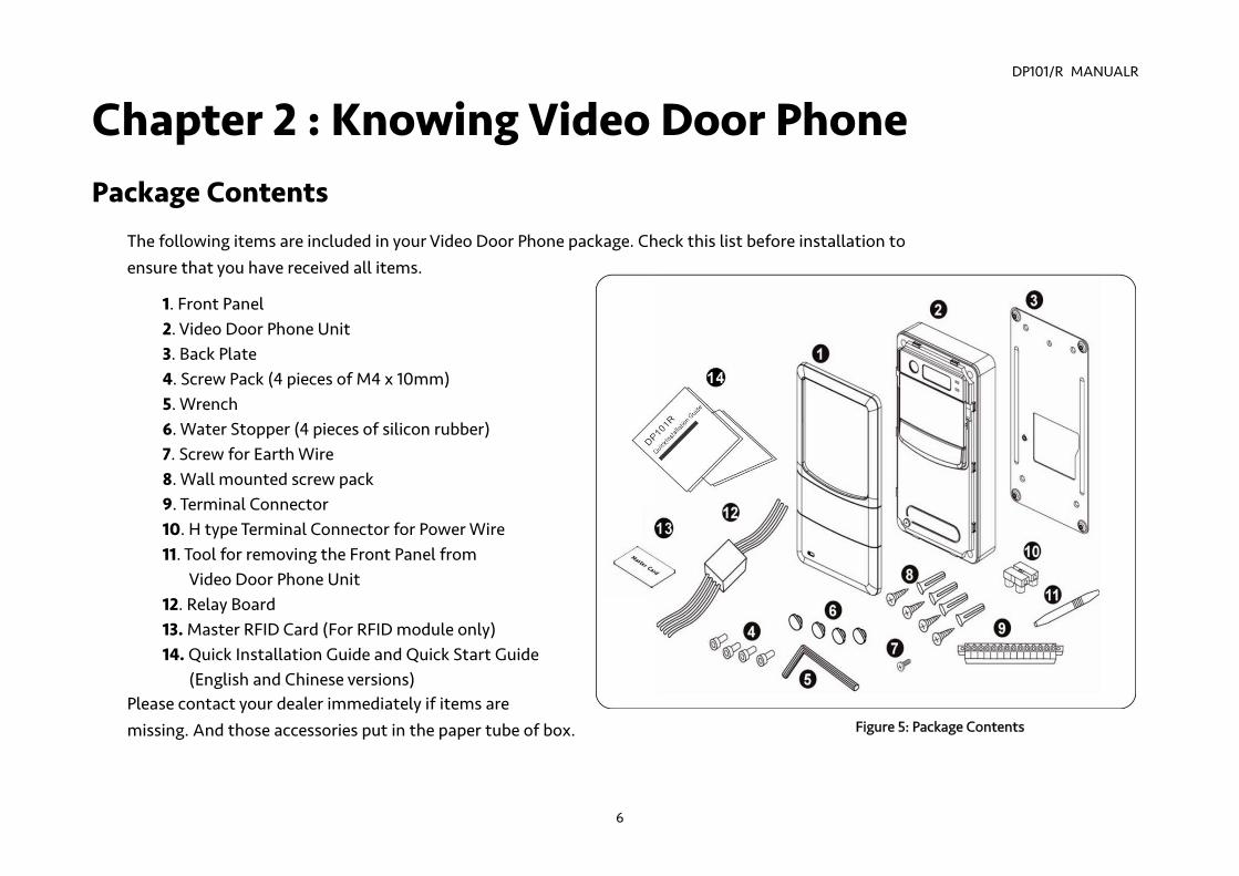
The following items are included in your Video Door Phone package. Check this list before installation to ensure that you have received all items.
1. Front Panel 2. Video Door Phone Unit 3. Back Plate 4. Screw Pack (4 pieces of M4 x 10mm) 5. Wrench 6. Water Stopper (4 pieces of silicon rubber) 7. Screw for Earth Wire 8. Wall mounted screw pack 9. Terminal Connector 10. H type Terminal Connector for Power Wire 11. Tool for removing the Front Panel from
Video Door Phone Unit 12. Relay Board 13. Master RFID Card (For RFID module only) 14. Quick Installation Guide and Quick Start Guide
(English and Chinese versions) Please contact your dealer immediately if items are missing. And those accessories put in the paper tube of box. Figure 5: Package Contents
DP101/R MANUALR
7
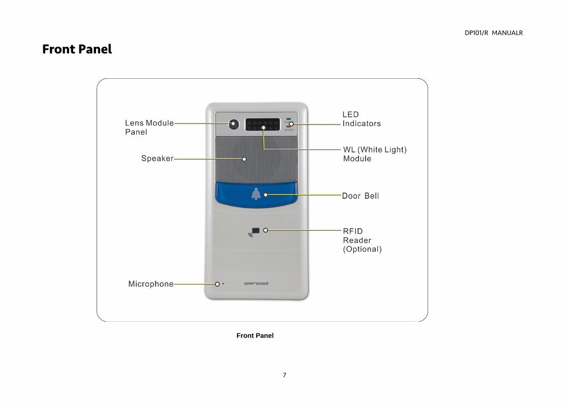
Front Panel
Front Panel
DP101/R MANUALR
8
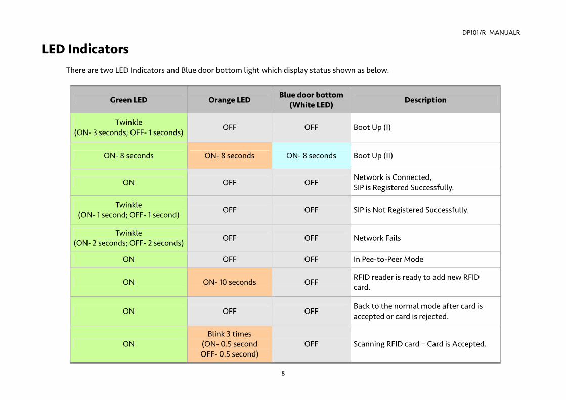
LED Indicators There are two LED Indicators and Blue door bottom light which display status shown as below.
Green LED Orange LED Blue door bottom (White LED) Description
Twinkle (ON- 3 seconds; OFF- 1 seconds)
OFF OFF Boot Up (I)
ON- 8 seconds ON- 8 seconds ON- 8 seconds Boot Up (II)
ON OFF OFF Network is Connected, SIP is Registered Successfully.
Twinkle (ON- 1 second; OFF- 1 second)
OFF OFF SIP is Not Registered Successfully.
Twinkle (ON- 2 seconds; OFF- 2 seconds)
OFF OFF Network Fails
ON OFF OFF In Pee-to-Peer Mode
ON ON- 10 seconds OFF RFID reader is ready to add new RFID card.
ON OFF OFF Back to the normal mode after card is accepted or card is rejected.
ON Blink 3 times
(ON- 0.5 second OFF- 0.5 second)
OFF Scanning RFID card – Card is Accepted.
DP101/R MANUAL
9
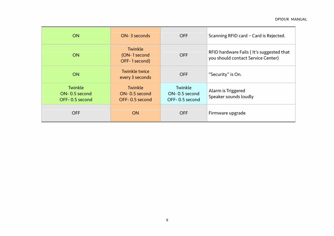
ON ON- 3 seconds OFF Scanning RFID card – Card is Rejected.
ON Twinkle
(ON- 1 second OFF- 1 second)
OFF RFID hardware Fails ( It’s suggested that you should contact Service Center)
ON Twinkle twice
every 3 seconds OFF “Security” is On.
Twinkle ON- 0.5 second OFF- 0.5 second
Twinkle ON- 0.5 second OFF- 0.5 second
Twinkle ON- 0.5 second OFF- 0.5 second
Alarm is Triggered Speaker sounds loudly
OFF ON OFF Firmware upgrade
DP101/R MANUAL
10
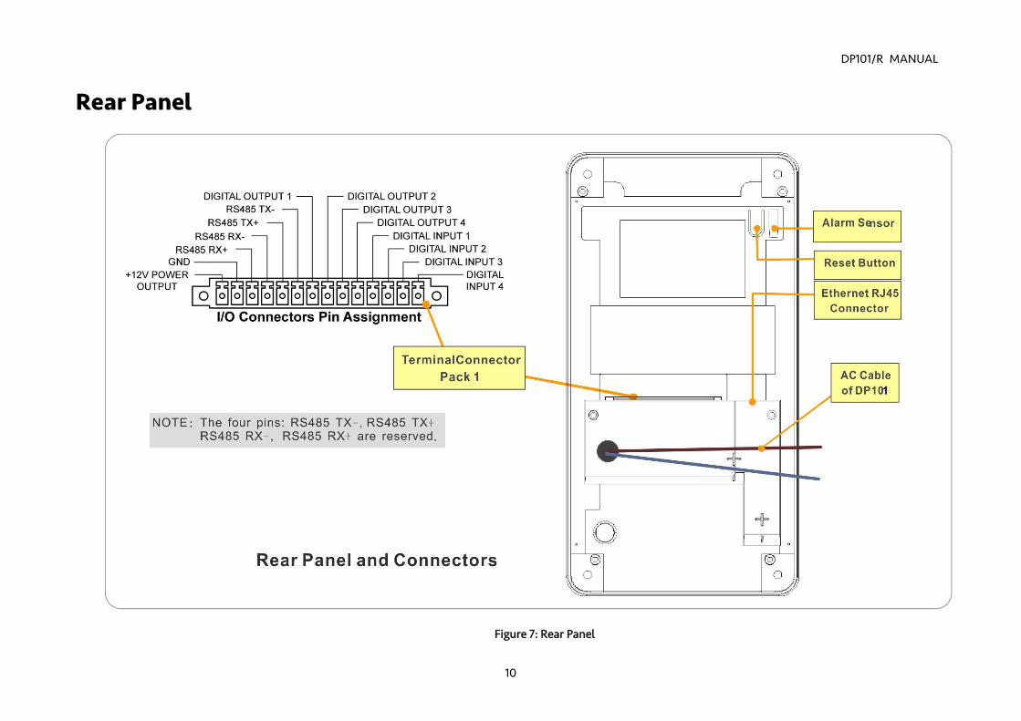
Rear Panel
Figure 7: Rear Panel
DP101/R MANUALR
11
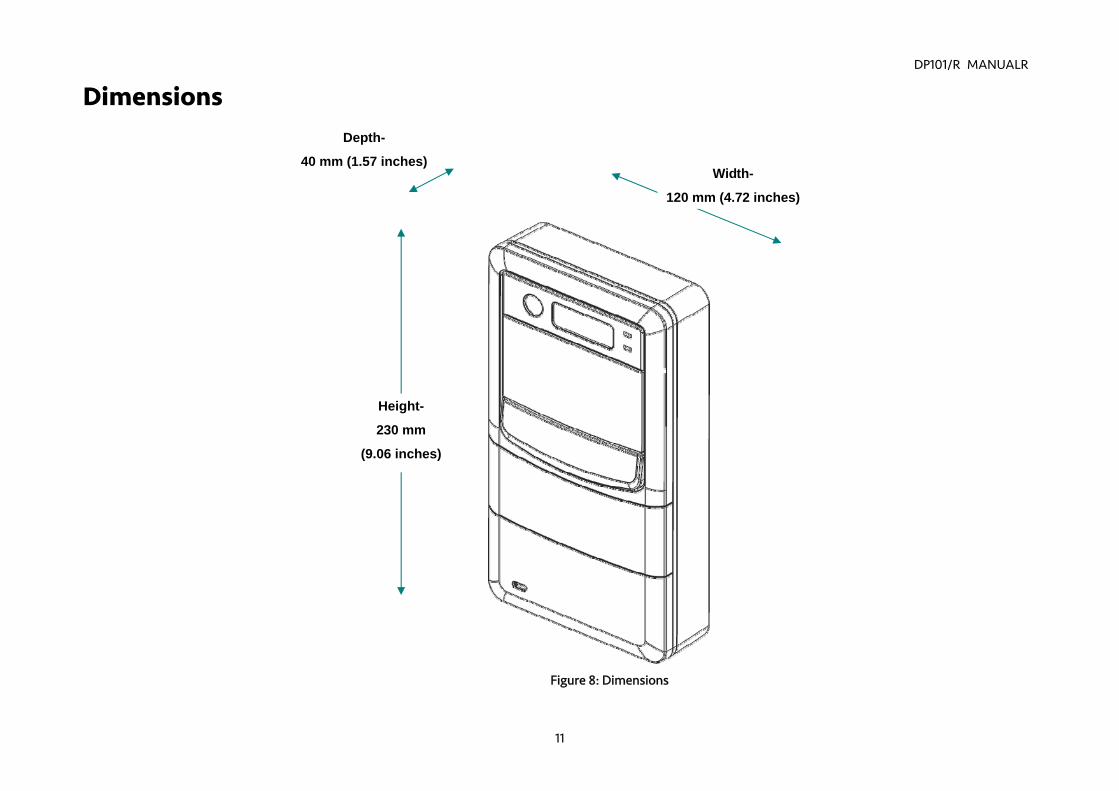
Dimensions Depth-
40 mm (1.57 inches)Width-
120 mm (4.72 inches)
Height-
230 mm
(9.06 inches)
Figure 8: Dimensions
DP101/R MANUALR
12
Chapter 3 : Installing Video Door Phone
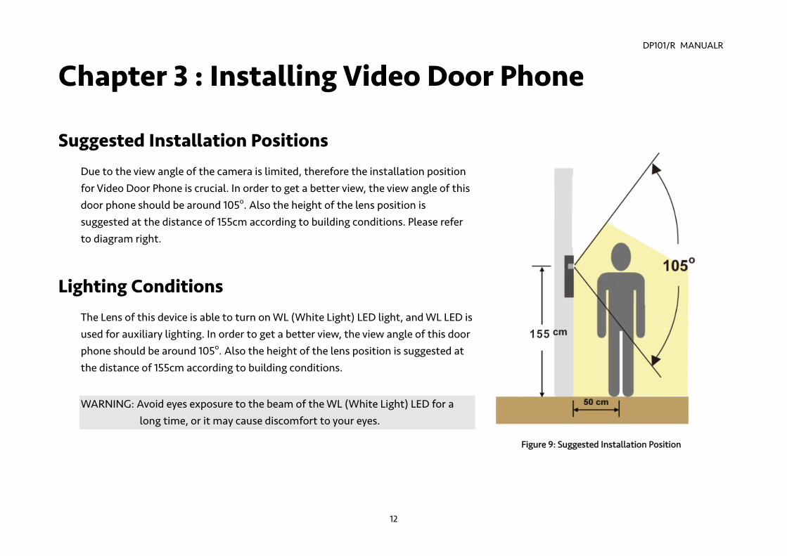
Suggested Installation Positions Due to the view angle of the camera is limited, therefore the installation position for Video Door Phone is crucial. In order to get a better view, the view angle of this door phone should be around 105o. Also the height of the lens position is suggested at the distance of 155cm according to building conditions. Please refer to diagram right.
Lighting Conditions The Lens of this device is able to turn on WL (White Light) LED light, and WL LED is used for auxiliary lighting. In order to get a better view, the view angle of this door phone should be around 105o. Also the height of the lens position is suggested at the distance of 155cm according to building conditions.
WARNING: Avoid eyes exposure to the beam of the WL (White Light) LED for a
long time, or it may cause discomfort to your eyes.
Figure 9: Suggested Installation Position
DP101/R MANUALR
13
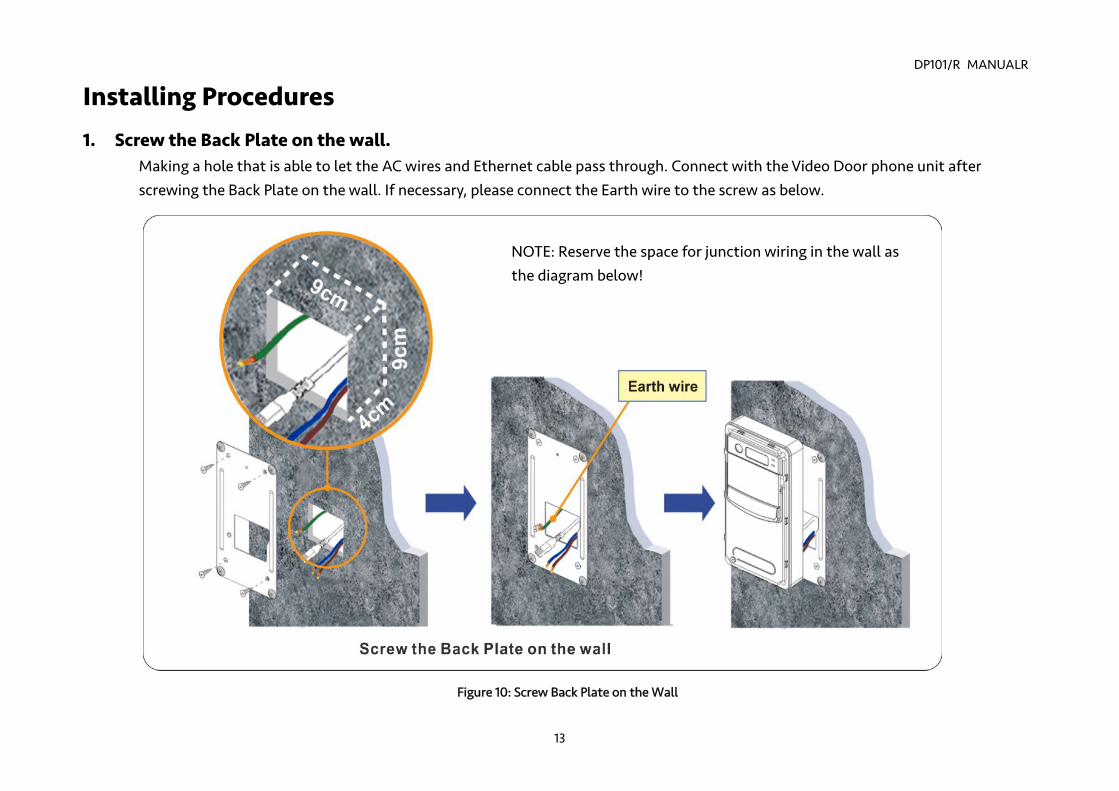
Installing Procedures 1. Screw the Back Plate on the wall.
Making a hole that is able to let the AC wires and Ethernet cable pass through. Connect with the Video Door phone unit after screwing the Back Plate on the wall. If necessary, please connect the Earth wire to the screw as below.
NOTE: Reserve the space for junction wiring in the wall as the diagram below!
Figure 10: Screw Back Plate on the Wall
DP101/R MANUALR
14
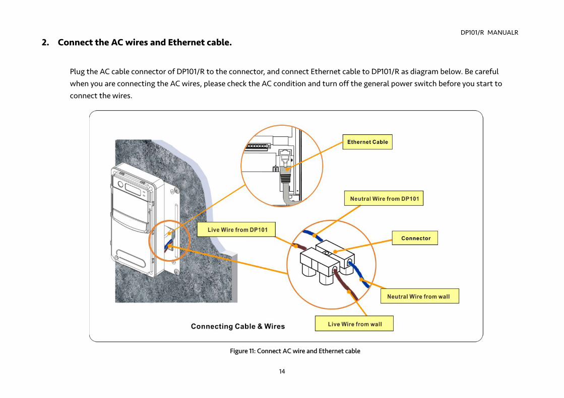
2. Connect the AC wires and Ethernet cable.
Plug the AC cable connector of DP101/R to the connector, and connect Ethernet cable to DP101/R as diagram below. Be careful when you are connecting the AC wires, please check the AC condition and turn off the general power switch before you start to connect the wires.
Figure 11: Connect AC wire and Ethernet cable
DP101/R MANUALR
15
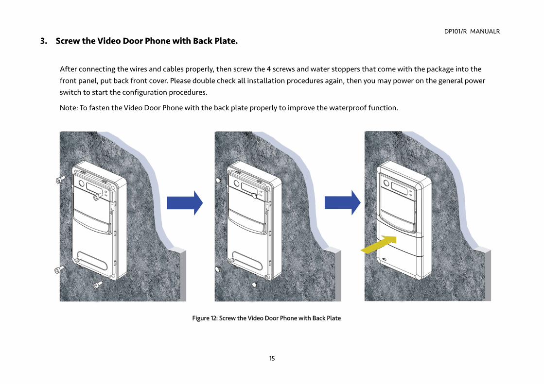
3. Screw the Video Door Phone with Back Plate.
After connecting the wires and cables properly, then screw the 4 screws and water stoppers that come with the package into the front panel, put back front cover. Please double check all installation procedures again, then you may power on the general power switch to start the configuration procedures.
Note: To fasten the Video Door Phone with the back plate properly to improve the waterproof function.
Figure 12: Screw the Video Door Phone with Back Plate
DP101/R MANUAL
16
Chapter 4 : Configuring Video Door Phone Finding Video Door Phone on Networks
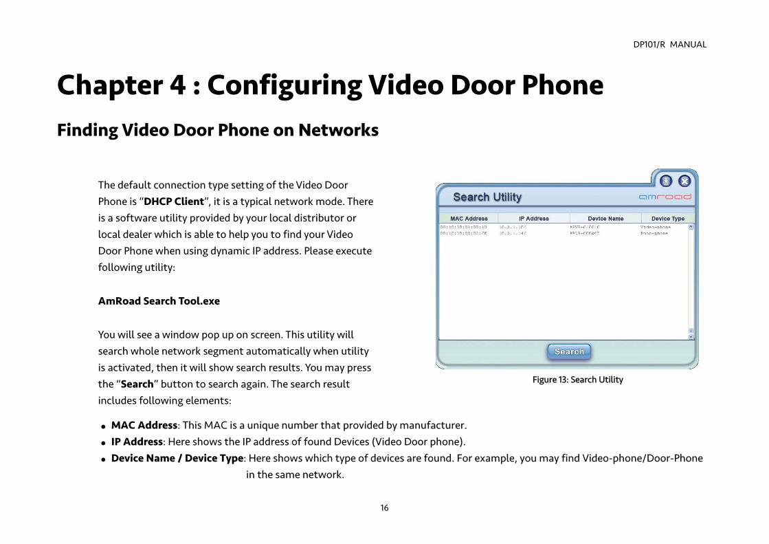
The default connection type setting of the Video Door Phone is “DHCP Client”, it is a typical network mode. There is a software utility provided by your local distributor or local dealer which is able to help you to find your Video Door Phone when using dynamic IP address. Please execute following utility:
AmRoad Search Tool.exe
You will see a window pop up on screen. This utility will search whole network segment automatically when utility is activated, then it will show search results. You may press the “Search” button to search again. The search result includes following elements:
MAC Address: This MAC is a unique number that provided by manufacturer. IP Address: Here shows the IP address of found Devices (Video Door phone). Device Name / Device Type: Here shows which type of devices are found. For example, you may find Video-phone/Door-Phone
in the same network.
Figure 13: Search Utility
DP101/R MANUAL
17
NOTE: 1. The default IP type setting of the Video Door Phone is “DHCP Client “. 2. There is a reset button on the back of the DP101/R
A. Pressing the reset button for 3 seconds=>DP101/R will turn into Statics IP mode as "192.168.0.50" and reboot by itself. B. Or pressing for over 6 seconds =>Turn to DHCP mode as the default value and reboot by itself (Restore to factory
setting). The issued RFID Cards data will be kept, but the Master Card1 data need to be set again.
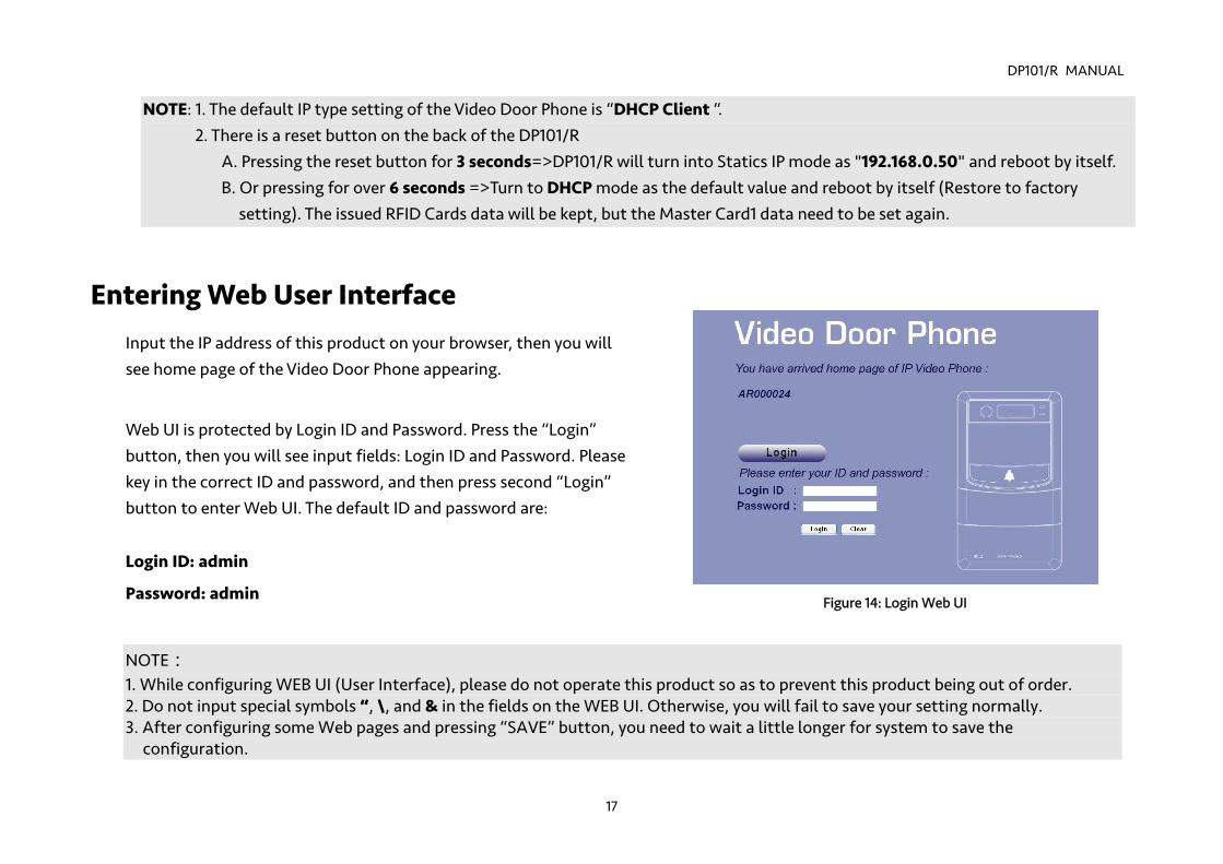
Entering Web User Interface Input the IP address of this product on your browser, then you will see home page of the Video Door Phone appearing.
Web UI is protected by Login ID and Password. Press the “Login” button, then you will see input fields: Login ID and Password. Please key in the correct ID and password, and then press second “Login” button to enter Web UI. The default ID and password are:
Login ID: admin
Password: admin
NOTE: 1. While configuring WEB UI (User Interface), please do not operate this product so as to prevent this product being out of order. 2. Do not input special symbols “, \, and & in the fields on the WEB UI. Otherwise, you will fail to save your setting normally. 3. After configuring some Web pages and pressing “SAVE” button, you need to wait a little longer for system to save the
configuration.
Figure 14: Login Web UI
DP101/R MANUAL
18
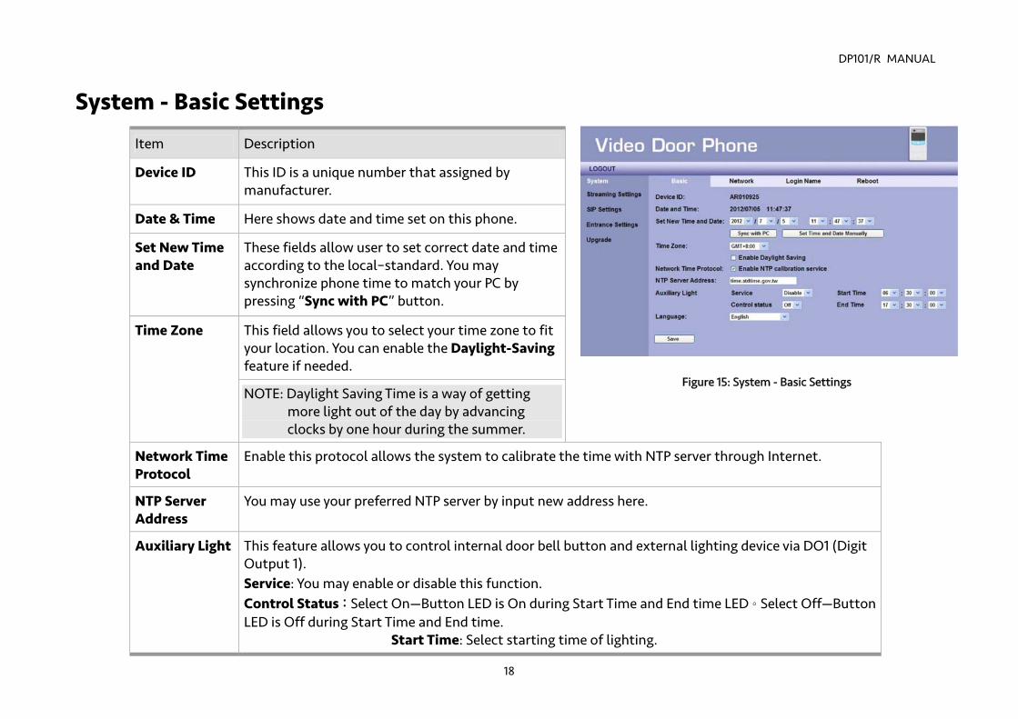
Figure 15: System - Basic Settings
System - Basic Settings
This field allows you to select your time zone to fit your location. You can enable the Daylight-Saving feature if needed.
Time Zone
NOTE: Daylight Saving Time is a way of getting more light out of the day by advancing clocks by one hour during the summer.
Network Time Protocol
Enable this protocol allows the system to calibrate the time with NTP server through Internet.
NTP Server Address
You may use your preferred NTP server by input new address here.
Auxiliary Light This feature allows you to control internal door bell button and external lighting device via DO1 (Digit Output 1). Service: You may enable or disable this function. Control Status:Select On—Button LED is On during Start Time and End time LED。Select Off—Button LED is Off during Start Time and End time.
Start Time: Select starting time of lighting.
Item Description
Device ID This ID is a unique number that assigned by manufacturer.
Date & Time Here shows date and time set on this phone.
Set New Time and Date
These fields allow user to set correct date and time according to the local–standard. You may synchronize phone time to match your PC by pressing “Sync with PC” button.

DP101/R MANUAL
19
End time: Select ending time of lighting.
NOTE: While setting Start Time and End Time, Start Time should be earlier than End Time.
Language This feature allows you to select the language of audio announcement. Select “English” or “Traditional Chinese”
Save Click this button to save your setting.
DP101/R MANUAL
20
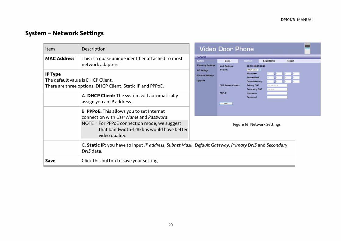
System – Network Settings
Item Description
MAC Address This is a quasi-unique identifier attached to most network adapters.
IP Type The default value is DHCP Client. There are three options: DHCP Client, Static IP and PPPoE.
A. DHCP Client: The system will automatically assign you an IP address.
B. PPPoE: This allows you to set Internet connection with User Name and Password. NOTE:For PPPoE connection mode, we suggest
that bandwidth-128kbps would have better video quality.
C. Static IP: you have to input IP address, Subnet Mask, Default Gateway, Primary DNS and Secondary DNS data.
Save Click this button to save your setting.
Figure 16: Network Settings
DP101/R MANUAL
21
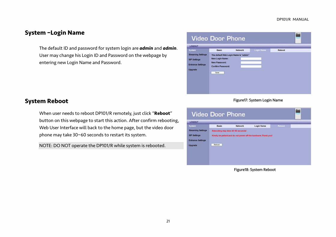
System –Login Name
The default ID and password for system login are admin and admin. User may change his Login ID and Password on the webpage by entering new Login Name and Password.
System Reboot
When user needs to reboot DP101/R remotely, just click “Reboot” button on this webpage to start this action. After confirm rebooting, Web User Interface will back to the home page, but the video door phone may take 30~60 seconds to restart its system.
NOTE: DO NOT operate the DP101/R while system is rebooted.
Figure18: System Reboot
Figure17: System Login Name
DP101/R MANUAL
22
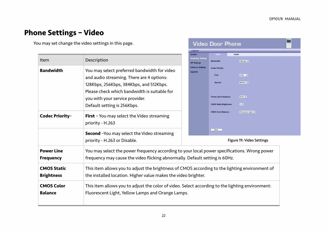
Phone Settings – Video You may set change the video settings in this page.
Item Description
Bandwidth You may select preferred bandwidth for video and audio streaming. There are 4 options: 128Kbps, 256Kbps, 384Kbps, and 512Kbps. Please check which bandwidth is suitable for you with your service provider. Default setting is 256Kbps.
Codec Priority– First – You may select the Video streaming priority - H.263
Second –You may select the Video streaming priority - H.263 or Disable.
Power Line Frequency
You may select the power frequency according to your local power specifications. Wrong power frequency may cause the video flicking abnormally. Default setting is 60Hz.
CMOS Static Brightness
This item allows you to adjust the brightness of CMOS according to the lighting environment of the installed location. Higher value makes the video brighter.
CMOS Color Balance
This item allows you to adjust the color of video. Select according to the lighting environment: Fluorescent Light, Yellow Lamps and Orange Lamps.
Figure 19: Video Settings
DP101/R MANUAL
23
NOTE: Fluorescent Light – This condition is suited for white lighting environment. Yellow Lamps – This condition is suited for indoor yellow bulb environment. Orange Lamps – This condition is suited for indoor orange color or more red color environments.
Save Click this button to save your setting.
NOTE: “Turn on/off WL LED” and “adjust the brightness of CMOS” via Video Door Phone prior to the “automatic CMOS Luma
detection” function. DP101/R can’t get the correct value of the CMOS brightness in some environment, please adjust the brightness value via the Video Door Phone by pressing “2”(brighter) or “8”(darker) in conversation state, or pressing “5” to turn on/off WL LED by yourself.
DP101/R MANUAL
24
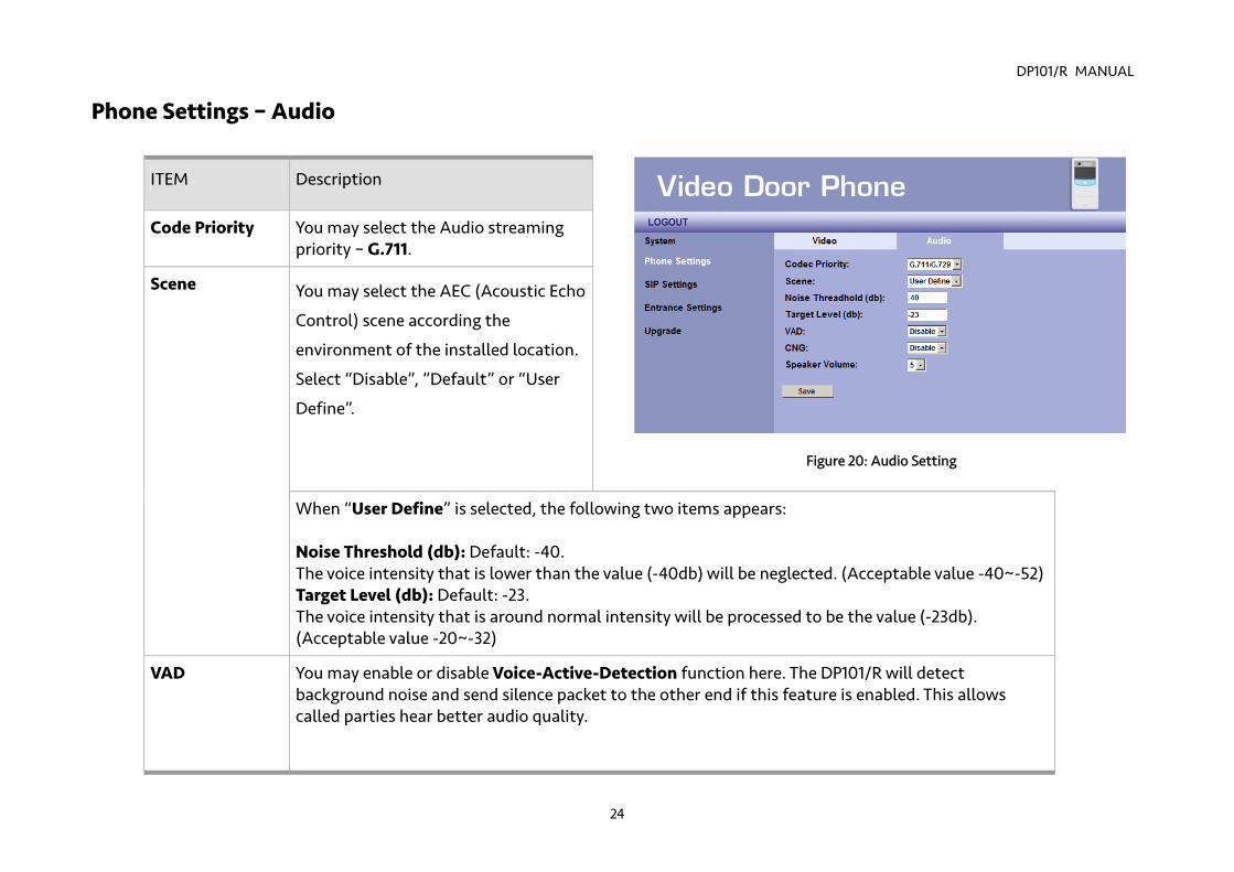
Phone Settings – Audio
ITEM Description
Code Priority You may select the Audio streaming priority – G.711.
You may select the AEC (Acoustic Echo
Control) scene according the
environment of the installed location.
Select “Disable”, ”Default” or “User
Define”.
Scene
When “User Define” is selected, the following two items appears: Noise Threshold (db): Default: -40. The voice intensity that is lower than the value (-40db) will be neglected. (Acceptable value -40~-52)Target Level (db): Default: -23. The voice intensity that is around normal intensity will be processed to be the value (-23db). (Acceptable value -20~-32)
VAD You may enable or disable Voice-Active-Detection function here. The DP101/R will detect background noise and send silence packet to the other end if this feature is enabled. This allows called parties hear better audio quality.
Figure 20: Audio Setting
DP101/R MANUAL
25
CNG You may enable or disable Comfortable-Noise-Generate function here. The DP101/R will generate background noise when receiving silence packet from the other end if this feature is enabled. This allows called parties hear better audio quality.
Speaker Volume
This item allows you to select volume of speaker. There are 10 levels, 0 ~ 9.
Save Click this button to save your setting.
DP101/R MANUAL
26
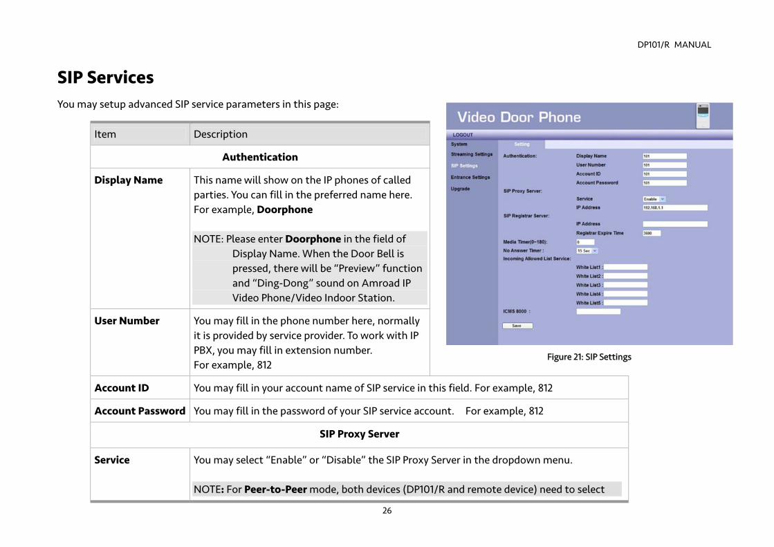
SIP Services You may setup advanced SIP service parameters in this page:
Item Description
Authentication
Display Name This name will show on the IP phones of called parties. You can fill in the preferred name here. For example, Doorphone NOTE: Please enter Doorphone in the field of
Display Name. When the Door Bell is pressed, there will be “Preview” function and “Ding-Dong” sound on Amroad IP Video Phone/Video Indoor Station.
User Number You may fill in the phone number here, normally it is provided by service provider. To work with IP PBX, you may fill in extension number. For example, 812
Account ID You may fill in your account name of SIP service in this field. For example, 812
Account Password You may fill in the password of your SIP service account. For example, 812
SIP Proxy Server
Service You may select “Enable” or “Disable” the SIP Proxy Server in the dropdown menu. NOTE: For Peer-to-Peer mode, both devices (DP101/R and remote device) need to select
Figure 21: SIP Settings
DP101/R MANUAL
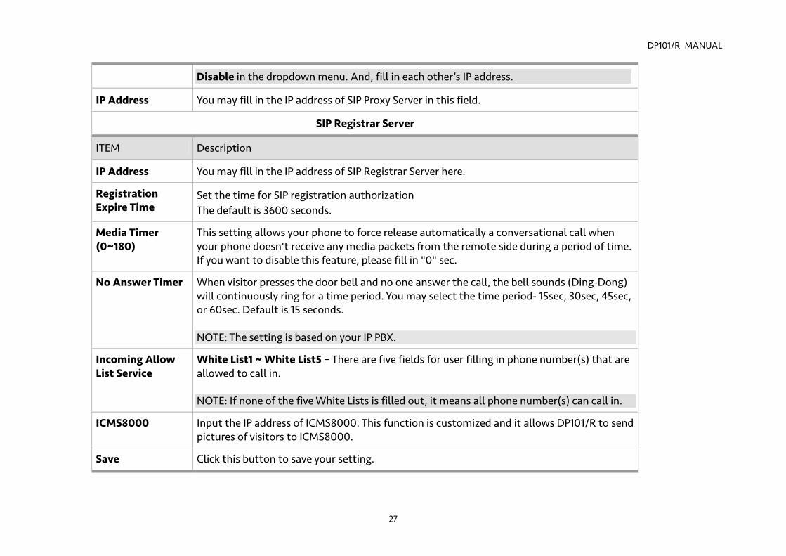
27
Disable in the dropdown menu. And, fill in each other’s IP address.
IP Address You may fill in the IP address of SIP Proxy Server in this field.
SIP Registrar Server
ITEM Description
IP Address You may fill in the IP address of SIP Registrar Server here.
Registration Expire Time
Set the time for SIP registration authorization The default is 3600 seconds.
Media Timer (0~180)
This setting allows your phone to force release automatically a conversational call when your phone doesn't receive any media packets from the remote side during a period of time. If you want to disable this feature, please fill in "0" sec.
No Answer Timer When visitor presses the door bell and no one answer the call, the bell sounds (Ding-Dong) will continuously ring for a time period. You may select the time period- 15sec, 30sec, 45sec, or 60sec. Default is 15 seconds. NOTE: The setting is based on your IP PBX.
Incoming Allow List Service
White List1 ~ White List5 – There are five fields for user filling in phone number(s) that are allowed to call in. NOTE: If none of the five White Lists is filled out, it means all phone number(s) can call in.
ICMS8000 Input the IP address of ICMS8000. This function is customized and it allows DP101/R to send pictures of visitors to ICMS8000.
Save Click this button to save your setting.
DP101/R MANUAL
28
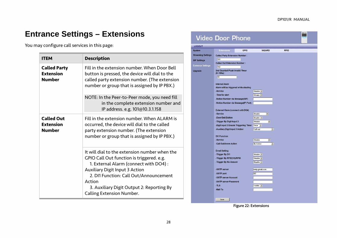
Entrance Settings – Extensions You may configure call services in this page:
ITEM Description
Called Party Extension Number
Fill in the extension number. When Door Bell button is pressed, the device will dial to the called party extension number. (The extension number or group that is assigned by IP PBX.) NOTE: In the Peer-to-Peer mode, you need fill
in the complete extension number and IP address. e.g. [email protected]
Fill in the extension number. When ALARM is occurred, the device will dial to the called party extension number. (The extension number or group that is assigned by IP PBX.)
Called Out Extension Number
It will dial to the extension number when the GPIO Call Out function is triggered. e.g.
1. External Alarm (connect with DO4) : Auxiliary Digit Input 3 Action
2. DI1 Function: Call Out/Announcement Action
3. Auxiliary Digit Output 2: Reporting By Calling Extension Number.
Figure 22: Extensions
DP101/R MANUAL
29
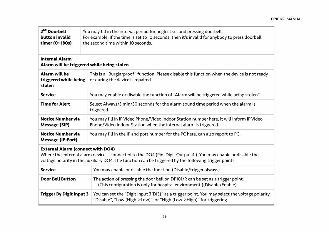
2nd Doorbell button invalid timer (0~180s)
You may fill in the interval period for neglect second pressing doorbell. For example, if the time is set to 10 seconds, then it’s invalid for anybody to press doorbell the second time within 10 seconds.
Internal Alarm Alarm will be triggered while being stolen
Alarm will be triggered while being stolen
This is a “Burglarproof” function. Please disable this function when the device is not ready or during the device is repaired.
Service You may enable or disable the function of “Alarm will be triggered while being stolen”.
Time for Alert Select Always/3 min/30 seconds for the alarm sound time period when the alarm is triggered.
Notice Number via Message (SIP)
You may fill in IP Video Phone/Video Indoor Station number here, it will inform IP Video Phone/Video Indoor Station when the internal alarm is triggered.
Notice Number via Message (IP:Port)
You may fill in the IP and port number for the PC here, can also report to PC.
External Alarm (connect with DO4) Where the external alarm device is connected to the DO4 (Pin: Digit Output 4 ). You may enable or disable the voltage polarity in the auxiliary DO4. The function can be triggered by the following trigger points.
Service You may enable or disable the function.(Disable/trigger always)
Door Bell Button The action of pressing the door bell on DP101/R can be set as a trigger point. (This configuration is only for hospital environment.)(Disable/Enable)
Trigger By Digit Input 3 You can set the “Digit Input 3(DI3)” as a trigger point. You may select the voltage polarity “Disable”, “Low (High->Low)”, or “High (Low->High)” for triggering.
DP101/R MANUAL
30
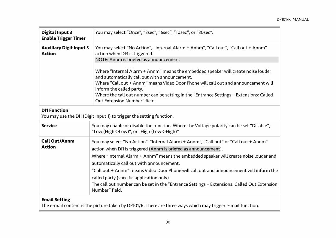
Digital Input 3 Enable Trigger Timer
You may select “Once”, “3sec”, “6sec”, “10sec”, or “30sec”.
Auxiliary Digit Input 3 Action
You may select ”No Action”, “Internal Alarm + Annm”, “Call out”, “Call out + Annm” action when DI3 is triggered. NOTE: Annm is briefed as announcement. Where “Internal Alarm + Annm” means the embedded speaker will create noise louder and automatically call out with announcement. Where “Call out + Annm” means Video Door Phone will call out and announcement will inform the called party. Where the call out number can be setting in the “Entrance Settings – Extensions: Called Out Extension Number” field.
DI1 Function You may use the DI1 (Digit Input 1) to trigger the setting function.
Service You may enable or disable the function. Where the Voltage polarity can be set “Disable”, “Low (High->Low)”, or “High (Low->High)”.
Call Out/Annm Action
You may select “No Action”, “Internal Alarm + Annm”, “Call out” or “Call out + Annm” action when DI1 is triggered (Annm is briefed as announcement). Where “Internal Alarm + Annm” means the embedded speaker will create noise louder and automatically call out with announcement. “Call out + Annm” means Video Door Phone will call out and announcement will inform the called party (specific application only). The call out number can be set in the “Entrance Settings – Extensions: Called Out Extension Number” field.
Email Setting The e-mail content is the picture taken by DP101/R. There are three ways which may trigger e-mail function.
DP101/R MANUAL
31
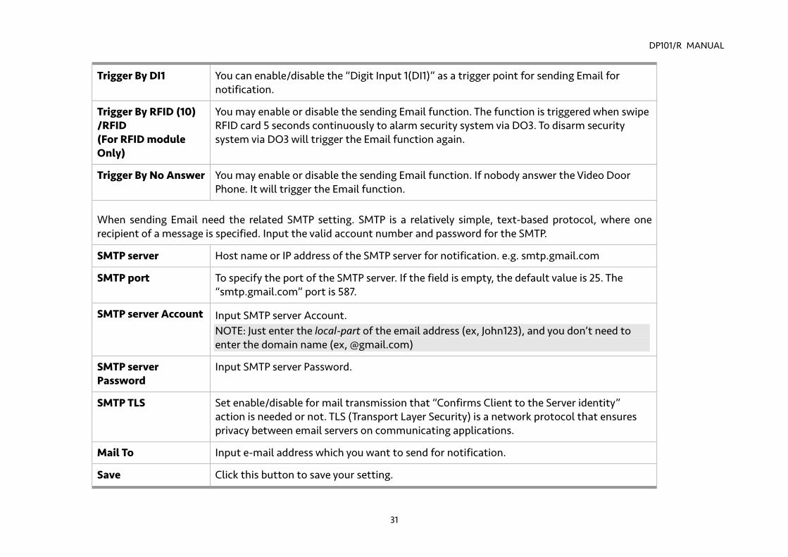
Trigger By DI1 You can enable/disable the “Digit Input 1(DI1)” as a trigger point for sending Email for notification.
Trigger By RFID (10) /RFID (For RFID module Only)
You may enable or disable the sending Email function. The function is triggered when swipe RFID card 5 seconds continuously to alarm security system via DO3. To disarm security system via DO3 will trigger the Email function again.
Trigger By No Answer You may enable or disable the sending Email function. If nobody answer the Video Door Phone. It will trigger the Email function.
When sending Email need the related SMTP setting. SMTP is a relatively simple, text-based protocol, where one recipient of a message is specified. Input the valid account number and password for the SMTP.
SMTP server Host name or IP address of the SMTP server for notification. e.g. smtp.gmail.com
SMTP port To specify the port of the SMTP server. If the field is empty, the default value is 25. The “smtp.gmail.com” port is 587.
SMTP server Account Input SMTP server Account. NOTE: Just enter the local-part of the email address (ex, John123), and you don’t need to enter the domain name (ex, @gmail.com)
SMTP server Password
Input SMTP server Password.
SMTP TLS Set enable/disable for mail transmission that “Confirms Client to the Server identity” action is needed or not. TLS (Transport Layer Security) is a network protocol that ensures privacy between email servers on communicating applications.
Mail To Input e-mail address which you want to send for notification.
Save Click this button to save your setting.
DP101/R MANUAL
32
NOTE: Be careful with the wires connection of GPIO, especially the default polar voltage of hardware (digit output pins) is high. Please select and set the related electric circuit to meet the hardware initial voltage.
DP101/R MANUAL
33
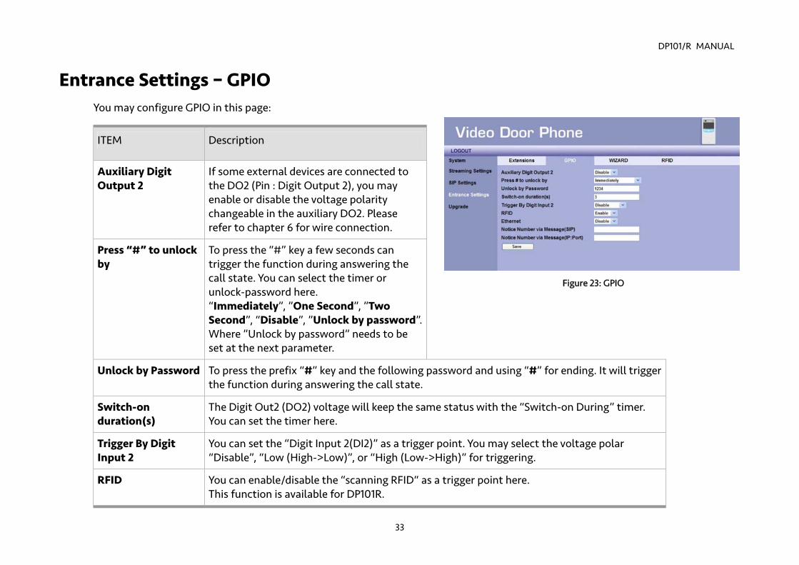
Figure 23: GPIO
Entrance Settings – GPIO You may configure GPIO in this page:
ITEM Description
Auxiliary Digit Output 2
If some external devices are connected to the DO2 (Pin : Digit Output 2), you may enable or disable the voltage polarity changeable in the auxiliary DO2. Please refer to chapter 6 for wire connection.
Press “#” to unlock by
To press the “#” key a few seconds can trigger the function during answering the call state. You can select the timer or unlock-password here. “Immediately”, ”One Second”, ”Two Second”, “Disable”, ”Unlock by password”. Where ”Unlock by password” needs to be set at the next parameter.
Unlock by Password To press the prefix “#” key and the following password and using “#” for ending. It will trigger the function during answering the call state.
Switch-on duration(s)
The Digit Out2 (DO2) voltage will keep the same status with the “Switch-on During” timer. You can set the timer here.
Trigger By Digit Input 2
You can set the “Digit Input 2(DI2)” as a trigger point. You may select the voltage polar “Disable”, “Low (High->Low)”, or “High (Low->High)” for triggering.
RFID
You can enable/disable the “scanning RFID“ as a trigger point here. This function is available for DP101R.
DP101/R MANUAL
34
Ethernet Some trusted Ethernets can be set up as a trigger point. Please contact with the provider when you need more information.
Notice Number via Message (SIP)
You may fill in the extension number here, it will send SIP Messages to the extension when the internal alarm is triggered.
Notice Number via Message (IP :Port)
You may fill in the IP and port number for the PC here. It will report to PC when the internal alarm is triggered.
Save Click this button to save your setting.
NOTE: Be careful with the wires connection of GPIO, especially the default polar voltage of hardware (digit output pins) is high. Please select and set the related electric circuit to meet the hardware initial voltage.
DP101/R MANUAL
35
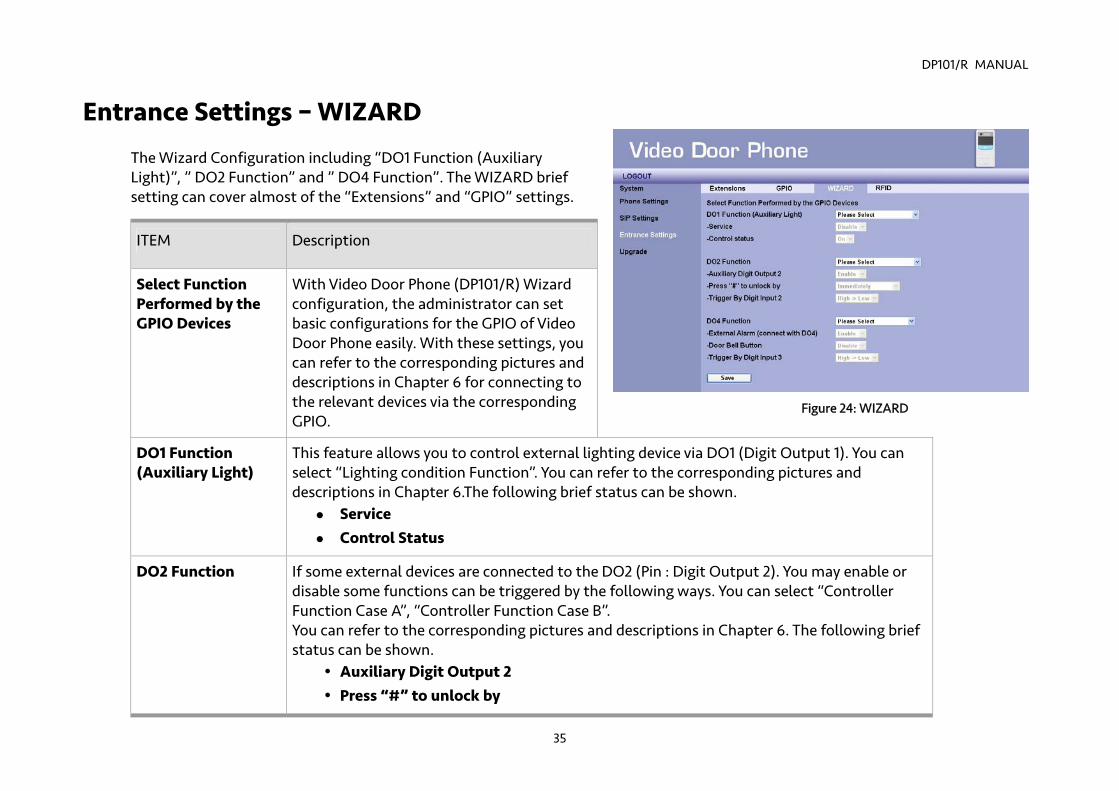
Entrance Settings – WIZARD
The Wizard Configuration including “DO1 Function (Auxiliary Light)”, ” DO2 Function” and ” DO4 Function”. The WIZARD brief setting can cover almost of the “Extensions” and “GPIO” settings.
ITEM Description
Select Function Performed by the GPIO Devices
With Video Door Phone (DP101/R) Wizard configuration, the administrator can set basic configurations for the GPIO of Video Door Phone easily. With these settings, you can refer to the corresponding pictures and descriptions in Chapter 6 for connecting to the relevant devices via the corresponding GPIO.
DO1 Function (Auxiliary Light)
This feature allows you to control external lighting device via DO1 (Digit Output 1). You can select “Lighting condition Function”. You can refer to the corresponding pictures and descriptions in Chapter 6.The following brief status can be shown.
Service Control Status
DO2 Function If some external devices are connected to the DO2 (Pin : Digit Output 2). You may enable or disable some functions can be triggered by the following ways. You can select “Controller Function Case A”, “Controller Function Case B”. You can refer to the corresponding pictures and descriptions in Chapter 6. The following brief status can be shown.
Auxiliary Digit Output 2 Press “#” to unlock by
Figure 24: WIZARD
DP101/R MANUAL
36
Trigger By Digit Input 2
DO4 Function If some external devices are connected to the DO4 (Pin : Digit Output 4). You may enable or disable some functions can be triggered by the following ways. You can select “Care Unit Function”, “Emergency Button Case A”, “C Emergency Button Case B”. If you need above applications, please contact with Amroad. The following brief status can be shown.
External Alarm connect with DO4) Door Bell Button Trigger By Digit Input 3
Save Click this button to save your setting.
NOTE: The most functions in WIZARD brief setting can be found in “Extensions” or “GPIO” settings.
DP101/R MANUAL
37
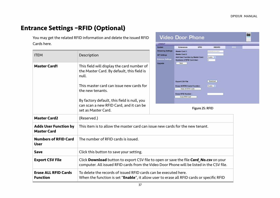
Entrance Settings –RFID (Optional) You may get the related RFID information and delete the issued RFID Cards here.
ITEM Description
Master Card1 This field will display the card number of the Master Card. By default, this field is null. This master card can issue new cards for the new tenants. By factory default, this field is null, you can scan a new RFID Card, and it can be set as Master Card.
Master Card2 (Reserved.)
Adds User Function by Master Card
This item is to allow the master card can issue new cards for the new tenant.
Numbers of RFID Card User
The number of RFID cards is issued.
Save Click this button to save your setting.
Export CSV File Click Download button to export CSV file to open or save the file Card_No.csv on your computer. All issued RFID cards from the Video Door Phone will be listed in the CSV file.
Erase ALL RFID Cards Function
To delete the records of issued RFID cards can be executed here. When the function is set “Enable”, it allow user to erase all RFID cards or specific RFID
Figure 25: RFID
DP101/R MANUAL
38
card. The item Erase RFID Number will appear. Then, you may input the specific issued RFID card number to delete it.
DP101/R MANUAL
39
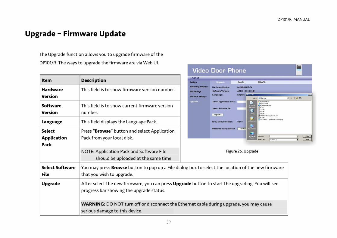
Upgrade – Firmware Update
The Upgrade function allows you to upgrade firmware of the
DP101/R. The ways to upgrade the firmware are via Web UI.
Item Description
Hardware Version
This field is to show firmware version number.
Software Version
This field is to show current firmware version number.
Language This field displays the Language Pack.
Select Application Pack
Press “Browse” button and select Application Pack from your local disk. NOTE: Application Pack and Software File
should be uploaded at the same time.
Select Software File
You may press Browse button to pop up a File dialog box to select the location of the new firmware that you wish to upgrade.
Upgrade After select the new firmware, you can press Upgrade button to start the upgrading. You will see progress bar showing the upgrade status. WARNING: DO NOT turn off or disconnect the Ethernet cable during upgrade, you may cause serious damage to this device.
Figure 26: Upgrade
DP101/R MANUAL
40
RFID Module Version
This field displays the version of the RFID Module. (For DP101R Only)
Restore Factory Default
Press the Restore Default button and wait for system to restore its original factory default setting.
DP101/R MANUAL
41
Configurations
Item Description
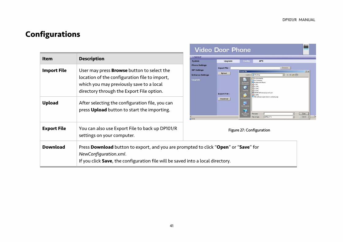
Import File User may press Browse button to select the location of the configuration file to import, which you may previously save to a local directory through the Export File option.
Upload After selecting the configuration file, you can press Upload button to start the importing.
Export File You can also use Export File to back up DP101/R settings on your computer.
Download Press Download button to export, and you are prompted to click “Open” or “Save” for NewConfiguration.xml. If you click Save, the configuration file will be saved into a local directory.
Figure 27: Configuration
DP101/R MANUAL
42
AR APS
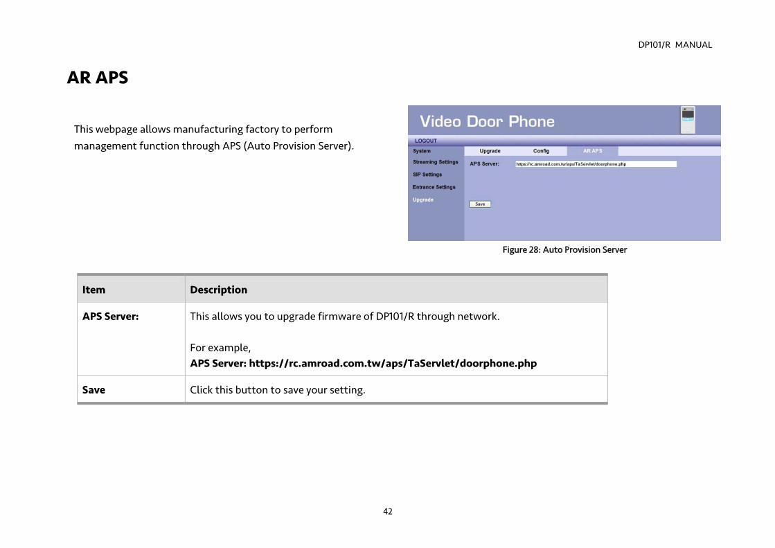
This webpage allows manufacturing factory to perform management function through APS (Auto Provision Server).
Item Description
APS Server: This allows you to upgrade firmware of DP101/R through network. For example, APS Server: https://rc.amroad.com.tw/aps/TaServlet/doorphone.php
Save Click this button to save your setting.
Figure 28: Auto Provision Server
DP101/R MANUAL
43
Chapter 5 : Using Video Door Phone Making Calls From Video Door Phone
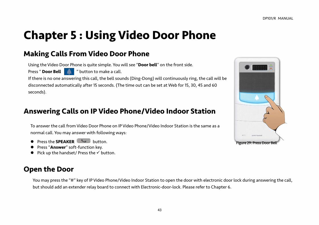
Using the Video Door Phone is quite simple. You will see “Door bell” on the front side. Press “ Door Bell ” button to make a call. If there is no one answering this call, the bell sounds (Ding-Dong) will continuously ring, the call will be disconnected automatically after 15 seconds. (The time out can be set at Web for 15, 30, 45 and 60 seconds).
Answering Calls on IP Video Phone/Video Indoor Station
To answer the call from Video Door Phone on IP Video Phone/Video Indoor Station is the same as a normal call. You may answer with following ways:
Press the SPEAKER button. Press “Answer” soft-function key. Pick up the handset/ Press the button.
Open the Door You may press the “#” key of IP Video Phone/Video Indoor Station to open the door with electronic door lock during answering the call, but should add an extender relay board to connect with Electronic-door-lock. Please refer to Chapter 6.
Figure 29: Press Door Bell
DP101/R MANUAL
44
Common Controls - You may press the “5” key of the IP Video Phone/Video Indoor Station to turn on/off the WL LED during answering the call. - You may press the “2” or “8” key of the IP Video Phone/Video Indoor Station to adjust the CMOS brightness.

DP101/R MANUAL
45
DP101R RFID Card Usage (Optional) Tenants scan RFID card on the reader. DP101R will verify the database to determine whether to open the door or not.
Issue RFID Master Card First Time For the first time, after the installation of DP101R is completed, take the Master RFID Card from package contents to scan on the DP101R RFID reader. This Master RFID card will be used as Master Card1. If you scan another RFID card instead of Master Card on DP101R reader for the first time, the first-time scanned RFID card will become RFID Master Card. NOTE: The Master Card is used for issuing new card, and it can NOT be used for opening door.
Upgrade a New Card with Master Card
Scan Master Card on DP101R First.
Within 10 seconds, scan New RFID Card on DP101R, DP101R Will Store New ID into Database.
Figure 30: Issue New Card
DP101/R MANUAL
46
Scanning RFID Card to Open Door
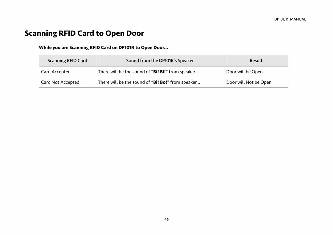
While you are Scanning RFID Card on DP101R to Open Door…
Scanning RFID Card Sound from the DP101R’s Speaker Result
Card Accepted There will be the sound of “Bi! Bi!” from speaker… Door will be Open
Card Not Accepted There will be the sound of “Bi! Bo!” from speaker… Door will Not be Open
DP101/R MANUAL
47
Chapter 6 : Applications Functions Performed by the Devices Electric Lock
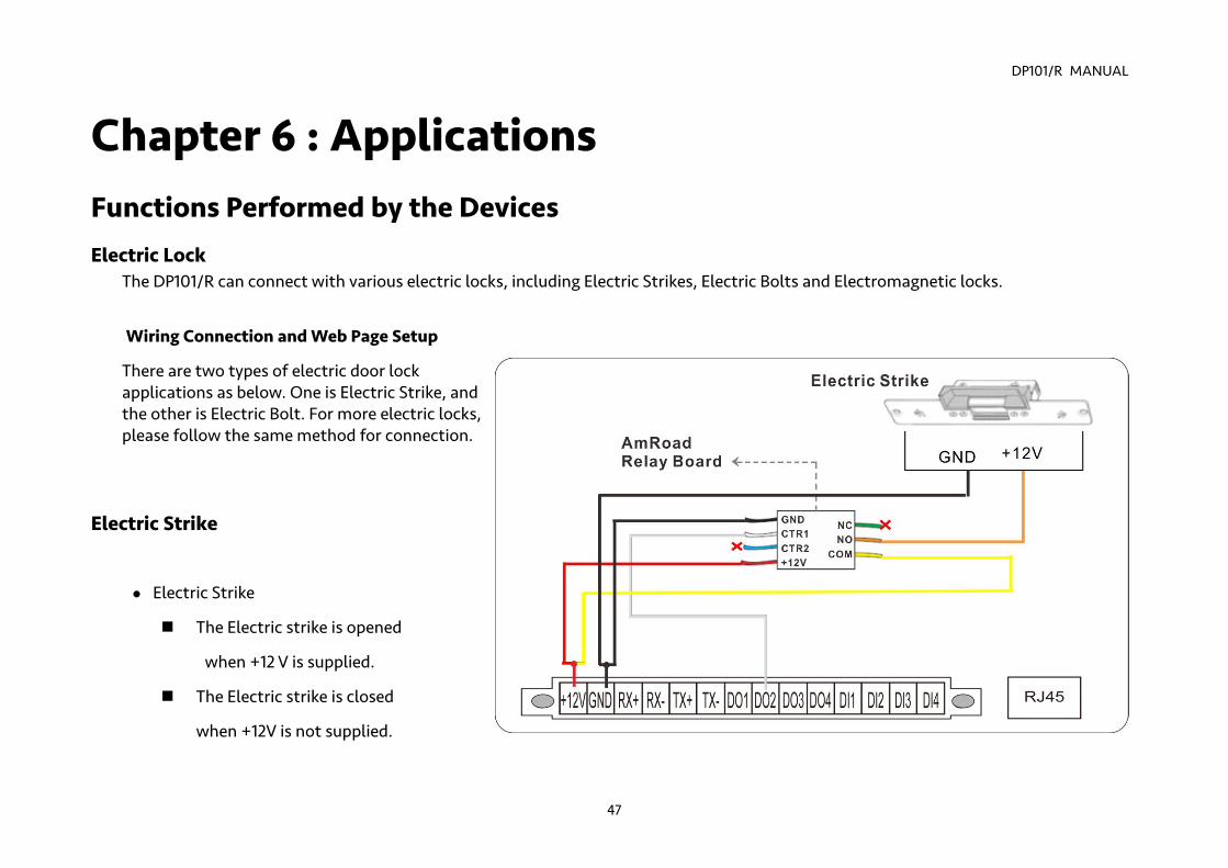
The DP101/R can connect with various electric locks, including Electric Strikes, Electric Bolts and Electromagnetic locks.
Wiring Connection and Web Page Setup
There are two types of electric door lock applications as below. One is Electric Strike, and the other is Electric Bolt. For more electric locks, please follow the same method for connection.
Electric Strike Electric Strike
The Electric strike is opened
when +12 V is supplied.
The Electric strike is closed
when +12V is not supplied.
DP101/R MANUAL
48
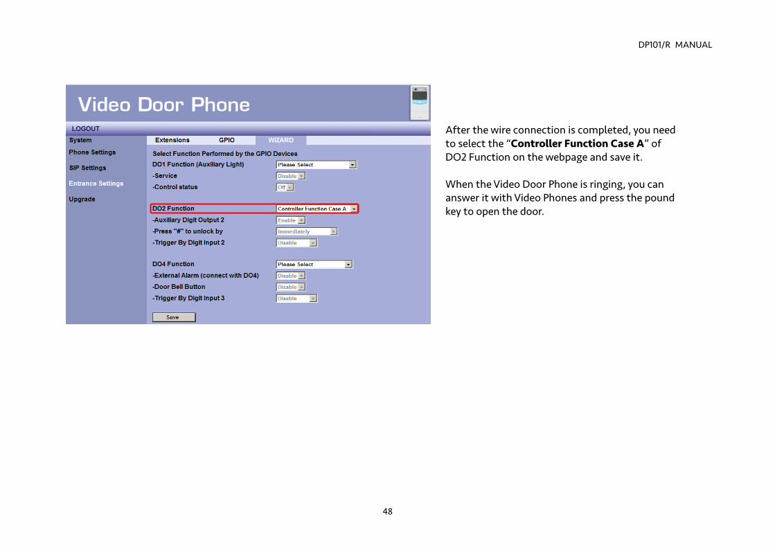
After the wire connection is completed, you need to select the “Controller Function Case A” of DO2 Function on the webpage and save it. When the Video Door Phone is ringing, you can answer it with Video Phones and press the pound key to open the door.
DP101/R MANUAL
49
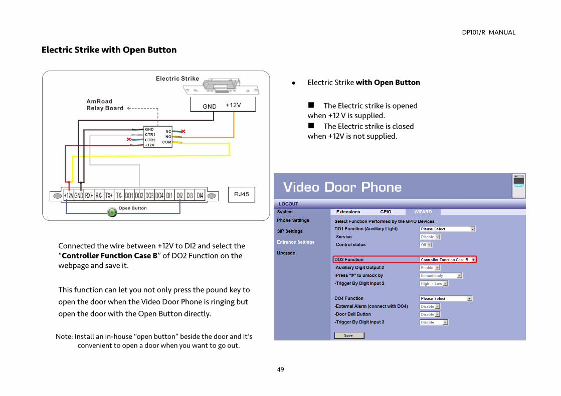
Electric Strike with Open Button
Electric Strike with Open Button
The Electric strike is opened when +12 V is supplied. The Electric strike is closed when +12V is not supplied.
Connected the wire between +12V to DI2 and select the “Controller Function Case B” of DO2 Function on the webpage and save it.
This function can let you not only press the pound key to open the door when the Video Door Phone is ringing but open the door with the Open Button directly.
Note: Install an in-house “open button” beside the door and it’s convenient to open a door when you want to go out.
DP101/R MANUAL
50
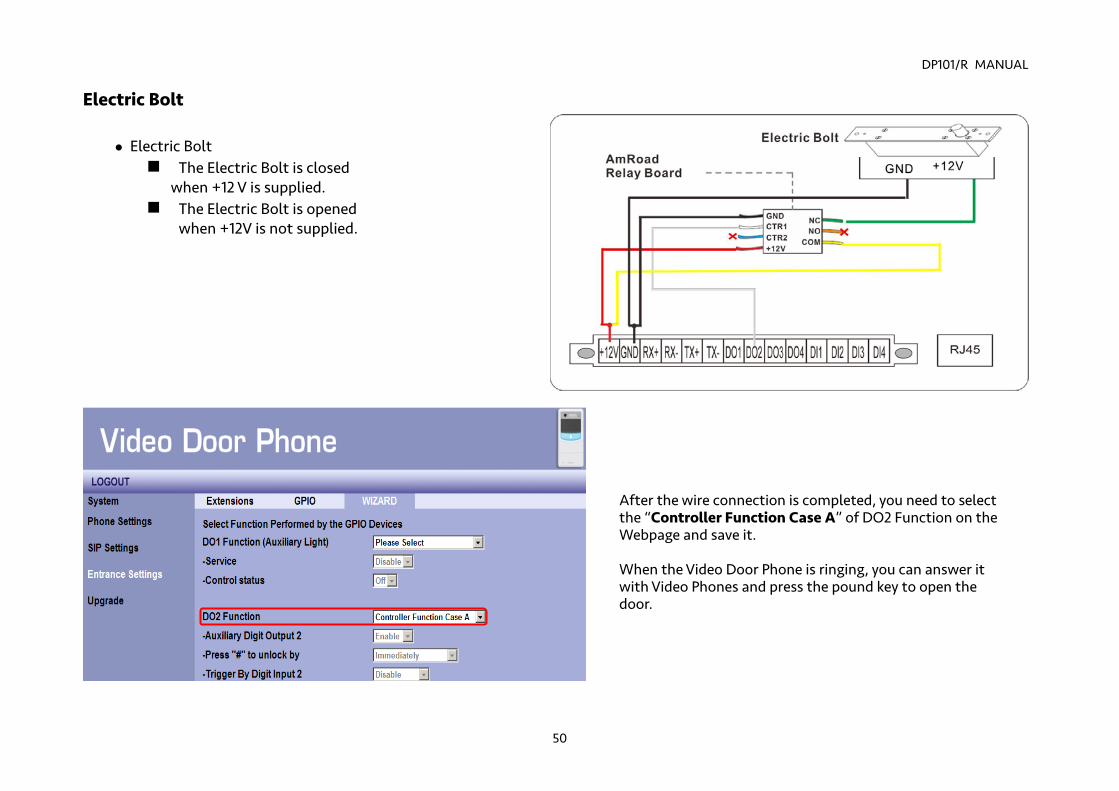
Electric Bolt
Electric Bolt The Electric Bolt is closed
when +12 V is supplied. The Electric Bolt is opened
when +12V is not supplied.
After the wire connection is completed, you need to select the “Controller Function Case A” of DO2 Function on the Webpage and save it. When the Video Door Phone is ringing, you can answer it with Video Phones and press the pound key to open the door.
DP101/R MANUAL
51
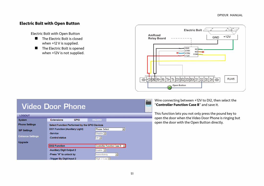
Electric Bolt with Open Button
Electric Bolt with Open Button The Electric Bolt is closed
when +12 V is supplied. The Electric Bolt is opened
when +12V is not supplied.
Wire connecting between +12V to DI2, then select the “Controller Function Case B” and save it. This function lets you not only press the pound key to open the door when the Video Door Phone is ringing but open the door with the Open Button directly.
DP101/R MANUAL
52
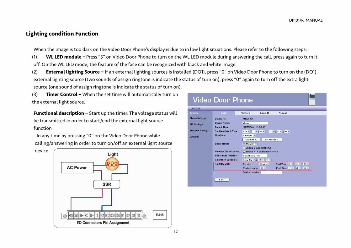
Lighting condition Function When the image is too dark on the Video Door Phone’s display is due to in low light situations. Please refer to the following steps:
(1) WL LED module – Press “5” on Video Door Phone to turn on the WL LED module during answering the call, press again to turn it off. On the WL LED mode, the feature of the face can be recognized with black and white image.
(2) External lighting Source − If an external lighting sources is installed (DO1), press “0” on Video Door Phone to turn on the (DO1) external lighting source (two sounds of assign ringtone is indicate the status of turn on), press “0” again to turn off the extra light source (one sound of assign ringtone is indicate the status of turn on).
(3) Timer Control − When the set time will automatically turn on the external light source.
Functional description − Start up the timer. The voltage status will be transmitted in order to start/end the external light source function -In any time by pressing “0” on the Video Door Phone while calling/answering in order to turn on/off an external light source device.
DP101/R MANUAL
53
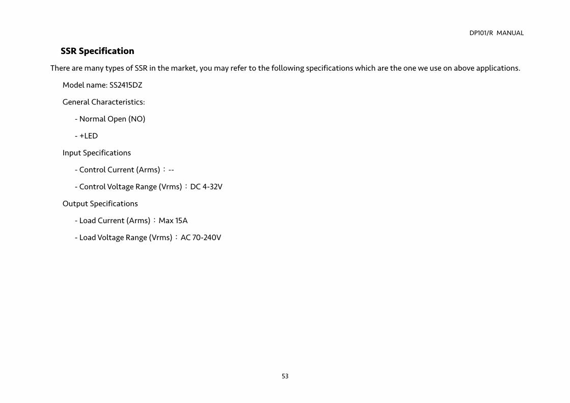
SSR Specification
There are many types of SSR in the market, you may refer to the following specifications which are the one we use on above applications.
Model name: SS2415DZ
General Characteristics:
- Normal Open (NO)
- +LED
Input Specifications
- Control Current (Arms):--
- Control Voltage Range (Vrms):DC 4-32V
Output Specifications
- Load Current (Arms):Max 15A
- Load Voltage Range (Vrms):AC 70-240V
DP101/R MANUAL
54
Functions Performed by the IP-PBX (Compatible with Amorad IP-PBX)
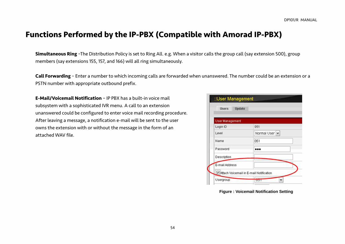
Simultaneous Ring –The Distribution Policy is set to Ring All. e.g. When a visitor calls the group call (say extension 500), group members (say extensions 155, 157, and 166) will all ring simultaneously. Call Forwarding – Enter a number to which incoming calls are forwarded when unanswered. The number could be an extension or a PSTN number with appropriate outbound prefix. E-Mail/Voicemail Notification – IP PBX has a built-in voice mail subsystem with a sophisticated IVR menu. A call to an extension unanswered could be configured to enter voice mail recording procedure. After leaving a message, a notification e-mail will be sent to the user owns the extension with or without the message in the form of an attached WAV file.
Figure : Voicemail Notification Setting
DP101/R MANUAL
55
Appendix A : Regulatory Information FCC STATEMENT
This product has been tested and complies with the specifications for a Class B digital device, pursuant to Part 15 of the FCC Rules. These limits are designed to provide reasonable protection against harmful interference in a residential installation. This equipment generates, uses, and can radiate radio frequency energy and, if not installed and used according to the instructions, may cause harmful interference to radio communications. However, there is no guarantee that interference will not occur in a particular installation. If this equipment does cause harmful interference to radio or television reception, which is found by turning the equipment off and on, the user is encouraged to try to correct the interference by one or more of the following measures:
Reorient or relocate the receiving antenna
Increase the separation between the equipment or devices
Connect the equipment to an outlet other than the receiver's
Consult a dealer or an experienced radio/TV technician for assistance
FCC Radiation Exposure Statement
This equipment complies with FCC radiation exposure limits set forth for an uncontrolled environment. This equipment should be installed and operated with minimum distance 20cm between the radiator and your body.
“Changes or modifications are not expressly approved by the manufacturer could void the user's authority to operate the equipment.”
DP101/R MANUAL
56
CE DECLARATION OF CONFORMITY (EUROPE)
Manufacturer declares that this product conforms to the specifications listed below, following the provisions of the European R&TTE directive 1999/5/EC:
EN 301 489-1, 301 489-17 General EMC requirements for Radio equipment
EN 609 50 Safety
EN 300-328-1, EN 300-328-2 Technical requirements for Radio equipment
Caution: This equipment is intended to be used in all EU and EFTA countries. Outdoor use may be restricted to certain frequencies and/or may require a license for operation. Contact local Authority for procedure to follow.
Note: Combinations of power levels and antennas resulting in a radiated power level of above 100 mW equivalent isotropic radiated power (EIRP) are considered as not compliant with the above mentioned directive and are not allowed for use within the European community and countries that have adopted the European R&TTE directive 1999/5/EC.