Embed Size (px)
Citation preview
AMS-251 / IP-420INSTRUCTION MANUAL
* "CompactFlash(TM)" is the registered trademark of SanDisk Corporation, U.S.A.

i
CONTENTS
I. MECHANICAL SECTION (WITH REGARD TO THE SEWING MACHINE) 11. SPECIFICATIONS ....................................................................................................... 12. CONFIGURATION ....................................................................................................... 23. INSTALLATION ........................................................................................................... 3
3-1. Removing the machine head fixing plate ....................................................................................33-2. Setting up the machine..................................................................................................................43-3. Preparations of switches...............................................................................................................63-4. Connecting the power switch .......................................................................................................73-5. Installing the panel.........................................................................................................................83-6. Installing the thread stand ............................................................................................................83-7. How to install the thread stand for bobbin winding ...................................................................93-8. Connecting the cord ....................................................................................................................103-9. Installing the air hose ..................................................................................................................133-10. Cautions for the compressed air supply (source of supply air) facility ...............................14
4. PREPARATION OF THE SEWING MACHINE .......................................................... 154-1. Lubrication....................................................................................................................................154-2. Adjusting the oil quantity in the hook ........................................................................................16
(1) Checking the oil quantity in the hook ..........................................................................................16(2) Adjusting the hook oil quantity (oil spots) ....................................................................................17(3) Sample of proper quantity of hook oil (oil spots) .........................................................................17
4-3. Checking the emergency stop switch ........................................................................................184-4. Attaching the needle ....................................................................................................................184-5. Needle size and gauge.................................................................................................................19
(1) Adjustment ..................................................................................................................................19(2) Gauge .........................................................................................................................................19
4-6. Threading the machine head ......................................................................................................204-7. Installing and removing the bobbin case ..................................................................................214-8. Installing the bobbin ....................................................................................................................214-9. Preparing the cassette clamp .....................................................................................................224-10. Adjusting the thread tension ....................................................................................................254-11. Intermediate presser height ......................................................................................................264-12. Adjusting the thread take-up spring ........................................................................................26
5. OPERATION OF THE SEWING MACHINE ............................................................... 275-1. Sewing...........................................................................................................................................27
II. OPERATION SECTION (WITH REGARD TO THE PANEL) .................... 281. PREFACE .................................................................................................................. 282. WHEN USING IP-420 ................................................................................................ 32
2-1. Name of each section of IP-420 ..................................................................................................322-2. Buttons to be used in common ..................................................................................................332-3. Basic operation of IP-420 ............................................................................................................342-4. LCD display section at the time of sewing shape selection ....................................................35
(1) Sewing shape data input screen .................................................................................................35(2) Sewing screen ............................................................................................................................37
2-5. Performing sewing shape selection ...........................................................................................392-6. Changing item data ......................................................................................................................41

ii
2-7. Checking pattern shape ..............................................................................................................432-8. Performing modification of needle entry point .........................................................................44
(1) Editing the thread tension ...........................................................................................................44(2) Editing the intermediate presser height ......................................................................................45
2-9. How to use temporary stop .........................................................................................................46(1) To continue performing sewing from some point in sewing ........................................................46(2) To perform re-sewing from the start ............................................................................................47
2-10. When setting of sewing product is difficult because of interruption of needle tip .............482-11. Winding bobbin thread ..............................................................................................................492-12. Using counter .............................................................................................................................51
(1) Setting procedure of the counter ................................................................................................51(2) Count-up releasing procedure ....................................................................................................53(3) How to change the counter value during sewing ........................................................................53
2-13. Performing new register of users’ pattern ...............................................................................542-14. Naming users’ pattern ...............................................................................................................552-15. Performing new register of pattern button ..............................................................................562-16. LCD display section at the time of pattern button selection .................................................57
(1) Pattern button data input screen .................................................................................................57(2) Sewing screen ............................................................................................................................59
2-17. Performing pattern button No. selection .................................................................................61(1) Selection from the data input screen ..........................................................................................61(2) Selection by means of the shortcut button ..................................................................................62
2-18. Changing contents of pattern button .......................................................................................632-19. Copying pattern button .............................................................................................................642-20. Changing sewing mode .............................................................................................................652-21. LCD display section at the time of combination sewing ........................................................66
(1) Pattern input screen ....................................................................................................................66(2) Sewing screen ............................................................................................................................68
2-22. Performing combination sewing ..............................................................................................70(1) Selection of combination data .....................................................................................................70(2) Creating procedure of the combination data ...............................................................................71(3) Deleting procedure of the combination data ...............................................................................72(4) Deleting procedure of the step of the combination data .............................................................72(5) Setting of the skip of steps ..........................................................................................................73
2-23. Using the simple operation mode ............................................................................................732-24. LCD display when the simple operation is selected...............................................................74
(1) Data input screen (individual sewing) .........................................................................................74(2) Sewing screen (individual sewing) ..............................................................................................77(3) Data input screen (combination sewing) .....................................................................................80(4) Sewing screen (combination sewing) .........................................................................................82
2-25. Changing memory switch data .................................................................................................842-26. Using information ......................................................................................................................85
(1) Observing the maintenance and inspection information .............................................................85(2) Releasing procedure of the warning ...........................................................................................86
2-27. Using communication function ................................................................................................87(1) Handling possible data ...............................................................................................................87(2) Performing communication by using the media ..........................................................................87(3) Performing communication by using USB ..................................................................................87(4) Take-in of the data ......................................................................................................................88(5) Taking in plural data together ......................................................................................................89
iii
2-28. Performing formatting of the media .........................................................................................912-29. Operation at the time of X/Y motor position slip .....................................................................92
(1) When the error is displayed during sewing .................................................................................92(2) When the error is displayed after end of sewing .........................................................................93(3) When the rest switch is not displayed .........................................................................................93
3. MEMORY SWITCH DATA LIST ................................................................................. 943-1. Data list .........................................................................................................................................943-2. Initial value list .............................................................................................................................99
4. ERROR CODE LIST ................................................................................................ 1015. MESSAGE LIST ...................................................................................................... 112
III. MAINTENANCE OF SAWING MACHINE ...............................................1151. MAINTENANCE ....................................................................................................... 115
1-1. Adjusting the height of the needle bar (Changing the length of the needle) ....................... 1151-2. Adjusting the needle-to-shuttle relation .................................................................................. 1161-3. Adjusting the vertical stroke of the intermediate presser ...................................................... 1181-4. The moving knife and counter knife......................................................................................... 1181-5. Thread breakage detector plate ............................................................................................... 1191-6. Amount of oil supplied to the hook .......................................................................................... 1191-7. Periodical cleaning of the oil shield ......................................................................................... 1191-8. Replacing the fuse .....................................................................................................................1201-9. Replenishing the designated places with grease ...................................................................121
(1) Types of grease ........................................................................................................................122(2) Points to be applied with JUKI Grease A ..................................................................................122
1-10. Troubles and corrective measures (Sewing conditions)......................................................1242. OPTIONAL ............................................................................................................... 126
2-1. List of the needle hole guides and intermediate pressers .....................................................1262-2. Bar code reader ..........................................................................................................................127
– 1 –
1. SPECIFICATIONS
I. MECHANICAL SECTION (WITH REGARD TO THE SEWING MACHINE)
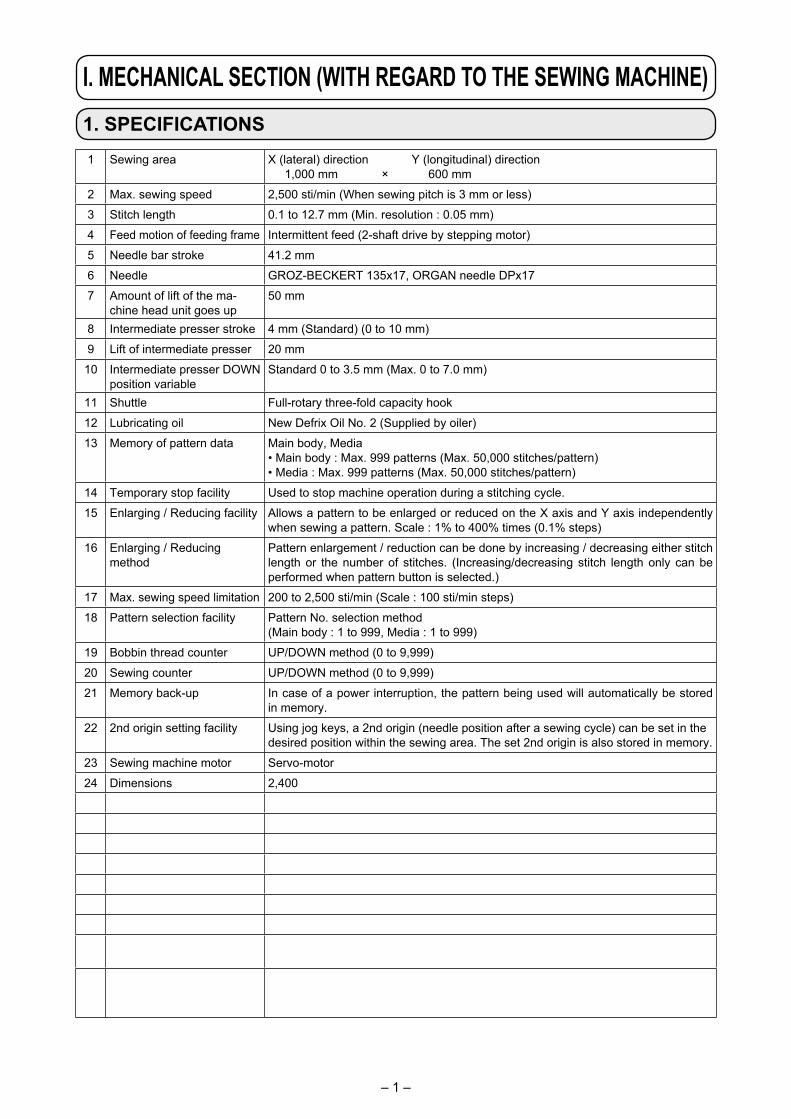
1 Sewing area X (lateral) direction Y (longitudinal) direction 1,000 mm × 600 mm
2 Max. sewing speed 2,500 sti/min (When sewing pitch is 3 mm or less)
3 Stitch length 0.1 to 12.7 mm (Min. resolution : 0.05 mm)
4 Feed motion of feeding frame Intermittent feed (2-shaft drive by stepping motor)
5 Needle bar stroke 41.2 mm
6 Needle GROZ-BECKERT 135x17, ORGAN needle DPx17
7 Amount of lift of the ma-chine head unit goes up
50 mm
8 Intermediate presser stroke 4 mm (Standard) (0 to 10 mm)
9 Lift of intermediate presser 20 mm
10 Intermediate presser DOWN position variable
Standard 0 to 3.5 mm (Max. 0 to 7.0 mm)
11 Shuttle Full-rotary three-fold capacity hook
12 Lubricating oil New Defrix Oil No. 2 (Supplied by oiler)
13 Memory of pattern data Main body, Media• Main body : Max. 999 patterns (Max. 50,000 stitches/pattern)• Media : Max. 999 patterns (Max. 50,000 stitches/pattern)
14 Temporary stop facility Used to stop machine operation during a stitching cycle.
15 Enlarging / Reducing facility Allows a pattern to be enlarged or reduced on the X axis and Y axis independently when sewing a pattern. Scale : 1% to 400% times (0.1% steps)
16 Enlarging / Reducing method
Pattern enlargement / reduction can be done by increasing / decreasing either stitch length or the number of stitches. (Increasing/decreasing stitch length only can be performed when pattern button is selected.)
17 Max. sewing speed limitation 200 to 2,500 sti/min (Scale : 100 sti/min steps)
18 Pattern selection facility Pattern No. selection method(Main body : 1 to 999, Media : 1 to 999)
19 Bobbin thread counter UP/DOWN method (0 to 9,999)
20 Sewing counter UP/DOWN method (0 to 9,999)
21 Memory back-up In case of a power interruption, the pattern being used will automatically be stored in memory.
22 2nd origin setting facility Using jog keys, a 2nd origin (needle position after a sewing cycle) can be set in the desired position within the sewing area. The set 2nd origin is also stored in memory.
23 Sewing machine motor Servo-motor
24 Dimensions 2,400 mm (W) × 1,800 mm (L) × 1,600 mm (H)
25 Mass (gross mass) 947 kg
26 Power consumption 800 VA
27 Operating temperature range 5˚C to 35˚C
28 Operating humidity range 35 % to 85 % (No dew condensation)
29 Line voltage Rated voltage ±10% 50 / 60 Hz
30 Air pressure used Standard 0.35 to 0.5 MPa (Max. 0.55 MPa)
31 Air consumption 1.8 dm3 / min (ANR)
32 Needle highest position stop facility
After the completion of sewing, the needle can be brought up to its highest position.
33 Noise - Equivalent continuous emission sound pressure level (LpA) at the workstation : A-weighted value of 78.2 dB; (Includes KpA = 2.5 dB); according to ISO 10821- C.6.2 -ISO 11204 GR2 at 2,500 sti/min *1.
*1 "sti/min" is an abbreviation for "stitches per minute."

– 2 –
Air regulator
2. CONFIGURATION
❶ Machine head❷ Cassette clamp❸ Intermediate presser❹ Thread stand❺ Operation panel (IP-420)❻ Power switch❼ Emergency stop switch❽ Start switch (green)❾ Pause switch (white)� Eject switch (blue)� Control box� Bobbin winder
❶
❼
�❾
❻
❺
�
❷
�
❸
❹
❽

– 3 –
3. INSTALLATION
3-1. Removing the machine head fixing plate
1) Open machine head safety cover ❶ .
Keep the machine head safety cover ❶ closed while the sewing machine is in operation.
❷
❸
2) Remove two setscrews ❷ . Detach machine head fixing plate ❸ .
3) Re-tighten two setscrews ❷ which you have removed in step 2) back in their tapped holes.
❶

– 4 –
3-2. Setting up the machine
1) Install the machine on a flat place with leveled.2) Loosen nut ❶ and turn level adjuster ❷ to lift
the machine until caster ❸ idles.3) After the machine has been set up properly,
tighten nut ❶ and fix level adjuster ❷ .
❶❷
❸
Use 0.3-mm/m levels for leveling the main body of device.
Overhead view
Worker side
[Positions to check with levels]1) Detach covers ❹ , ❺ , ❻ and ❼ of the main
body of device at four locations by removing their screws.
2) Place a level respectively at positions A indicat-ed in the figure. Adjust the adjusters mounted at four corners so that the number of lines indicat-ed on the level scale plate is within two.
After checking the levelness, adjust the adjuster located at the center section of each strut until it is stretched. Then, give it a 1/8 turn to further stretch it. In this state, fix each adjuster.
3) After the adjustment, re-place the covers back in place.
A
A
A
❹
❺
❼ ❻

– 5 –
1) Remove screw ❶ . Detach needle hole guide ❷ .
[Checking the needle entry]
2) Turn machine head ❸ and hook section ❹ so that they face the front.
Align marker line A on the bearing with marker line B on gear ring.
4) Turn the hand pulley of machine head until needle-bar marker line ❽ is aligned with the lower end of needle bar bushing ❾ .
5) Check to make sure that a clearance of 0.03 to 0.1 mm is provided between the needle and the hook blade point � when the hook blade point is aligned with the center of needle.
For each of four directions, check steps 2) to 4) by turning the machine head and hook section in steps of 90 degrees.
If the clearance of 0.03 to 0.1 mm is not pro-vided between the needle and the hook blade point, re-adjust the levelness of the main body of device.
3) Inserting hook shaft fixing rod ❻ into hook shaft fixing rod insertion hole ❺ , turn pulley ❼ until hook shaft fixing rod ❻ is fully inserted into the hole. (As a guide, turn the pulley until the hook blade point is brought to the position at which it faces upward.)
❺
❻
❼
�
0.03 to 0.1mm
❶❷
❽
❾
❹B
A
A
B
❸
– 6 –
3-3. Preparations of switches
Loosen respective screws ❶ of the power switch, start switch and emergency stop switch which are placed upside down. Then, place the switches so that they face the worker side and re-tighten the screws.
❶
❶
❶
– 7 –
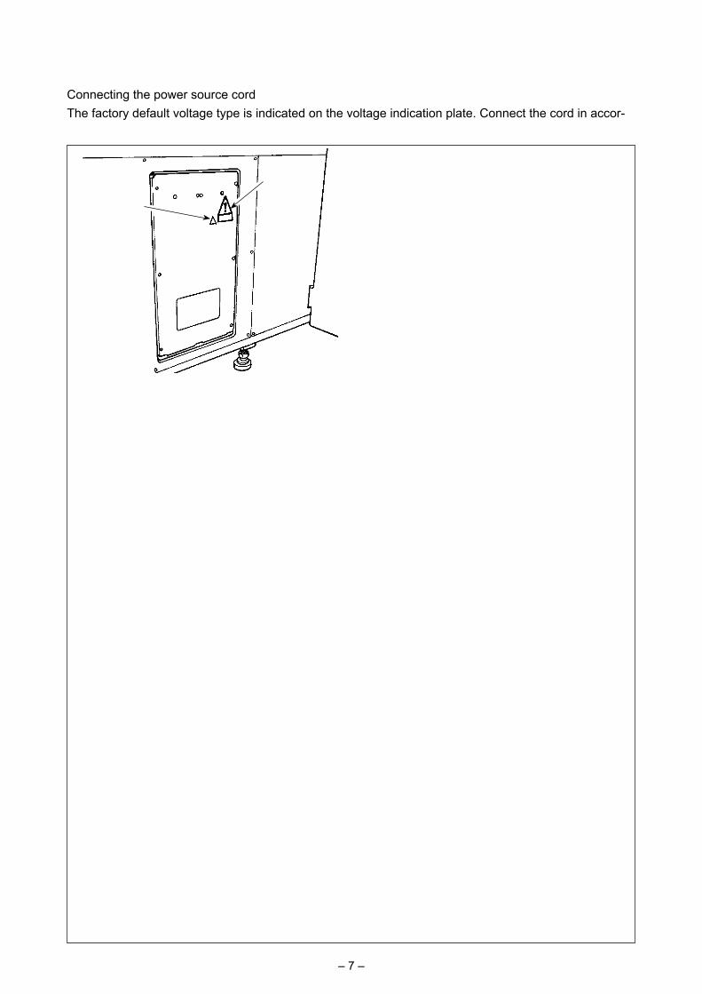
Connecting the power source cordThe factory default voltage type is indicated on the voltage indication plate. Connect the cord in accor-dance with the specifications.
Voltage caution seal
Never use under the wrong voltage and phase.
Electric shock warning label
3-4. Connecting the power switch
Brown OR Black-No.1
Brown OR Black-No.1
Light blue OR BLACK-No.2
Light blue OR BLACK-No.2
Light blue OR BLACK-No.2Green/Yellow
– GND
Green/Yellow
Plug
Power source cord
Power switch
AC200 V, AC220 VAC230 V, AC240 V
• Connecting single phase 200V, 220V, 230V and 240V
White
AC200 V, AC220 V, AC240 V
• Connecting three phase 200V, 220V and 240V
Red WhiteBlack
Table
Control box
Black
Red
Green/Yellow
Green/Yellow– GND
Red
Green
PlugControl box
Green/Yellow
Black
White
Power switch
Table
Brown OR Black-No.1
– 8 –
3-6. Installing the thread stand
3-5. Installing the panel
1) Fix operation box mounting plate ❶ with two wood screws ❷ .
Install the panel at the position where X-move cover or head grip does not interfere with it since breakage of the panel will be caused.
1) Open machine head safety cover ❶ .
Keep the machine head safety cover ❶ closed while the sewing machine is in operation.
2) Fix thread guide plate ❷ with setscrews ❸ (two small screws).
3) Fix thread stand mounting plate ❹ with set-screws ❺ (three large screws).
4) Attach setscrew ❼ in thread winder support block ❻ .
5) Put the thread on bobbin winder support rod ❽ , Insert bobbin winder support block ❻ into bob-bin winder support rod ❽ and fix with setscrew ❼ .
❶
❷
❶
❽
❼
❸
❹ ❺
❻❷

– 9 –
1) Pass thread stand arm ❷ over spool rest rod ❶ and fix with thread stand arm setscrew ❸ and thread stand arm lock nut ❹ .
Fit thread stand protection cap ❺ over the top end of thread stand ❶ .
2) Put thread path bush ❻ and thread path ❼ in holes (two locations) in thread stand arm ❷ in the written order.
3) Attach spool rest rod lock nut (small) ❽ , rub-ber washer ❾ and thread stand lock washer � to the lower end of spool rest rod ❶ . Then, fit the spool rest rod in the hole in bobbin winder base � and fix with thread spool rest rod lock nut (large) � .
4) Attach bobbin winder anti-vibrator � , bobbin winder tray cushion � and bobbin winder tray � to bobbin winder support rod � . Then, fix them on bobbin winder base � with a screw.
5) Attach bobbin winder support rod lock plain washer � , bobbin winder support rod lock spring washer � and bobbin winder support rod lock nut � to the section of screw that pro-trudes from the undersurface of bobbin winder base � and fix them.
3-7. How to install the thread stand for bobbin winding
❻
❼
❸❹
❷
❶
�
�
❽
� ����
❺
�❾�
�❾
�

– 10 –
[How to open the control box]
Remove six screws ❷ which secure the front cover of control box. When opening the front cover, open it by holding it and turning carefully by approximately 90°until it will go no further, as shown in the figure.
Be sure to hold the cover with hands in order to prevent it from dropping.In this case, do not apply an extra load to the front cover you have opened.
3-8. Connecting the cord
[How to close the control box]1) Close the front cover by pushing its lower
side A and fix with six screws ❷ while adding special care not to allow cables to be caught between the front cover and the control box.
2) Lower downward the cord located on the side of the control box and cord presser plate C in the push hole B, press the cord and tighten screws ❸ .
Slowly
❸A
C
B
❷
❷
[How to detach the cover]
Remove eight setscrews ❶ of the side cover.
❶
DANGER :1. To prevent personal injuries caused by electric shock hazards or abrupt start of the sewing
machine, carry out the work after turning OFF the power switch and a lapse of 5 minutes or more.2. To prevent accidents caused by unaccustomed work or electric shock, request the electric expert
or engineer of our dealers when adjusting the electrical components.

– 11 –
[Inside of the control box]
MAIN PCB
CN49 8P
CN65 6P
CN64 14P
CN63 12P
CN62 10P
CN38 12P
CN40 8P
CN48 12P
CN36 8PCN43 6P
CN46 4P
CN37 10P
CN39 26P
CN53 3PCN50 4P
CN60 8P
CN61 12P
CN58 10P
CN59 9P
CN55 2PCN42 10PCN57 6P
CN31 10PCN41 9P
CN56 6PCN45 7P CN44 7P
CN47 4P
CN34 20P CN52 3PCN35 50P
CN54 2P
CN32 8P
CN66 4P
SDC PCB
MAIN PCBPWR PCB
FLT PCBFLT-T PCB (single phase 100 to 200V、three phase 200 to 240V)FLT-S PCB (single phase 200 to 240V)
– 12 –
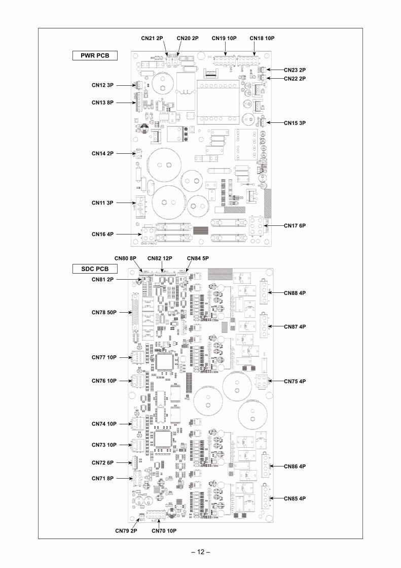
PWR PCB
SDC PCB
CN23 2PCN22 2P
CN15 3P
CN17 6P
CN18 10PCN20 2P CN19 10PCN21 2P
CN12 3P
CN13 8P
CN14 2P
CN11 3P
CN16 4P
CN88 4P
CN87 4P
CN75 4P
CN86 4P
CN85 4P
CN84 5PCN82 12PCN80 8P
CN81 2P
CN78 50P
CN72 6P
CN77 10P
CN76 10P
CN74 10P
CN73 10P
CN71 8P
CN70 10PCN79 2P

– 13 –
3-9. Installing the air hose
1) Connecting the air hose Connect the air hose to the regulator.2) Adjustment of air pressure Open air cock ❶ , pull up and turn air adjust-
ment knob ❷ and adjust so that air pressure indicates 0.45 to 0.5 MPa (Max. 0.55 MPa). Then lower the knob and fix it.
* Close air cock ❶ to expel air.
❶
❷Close
Open
– 14 –
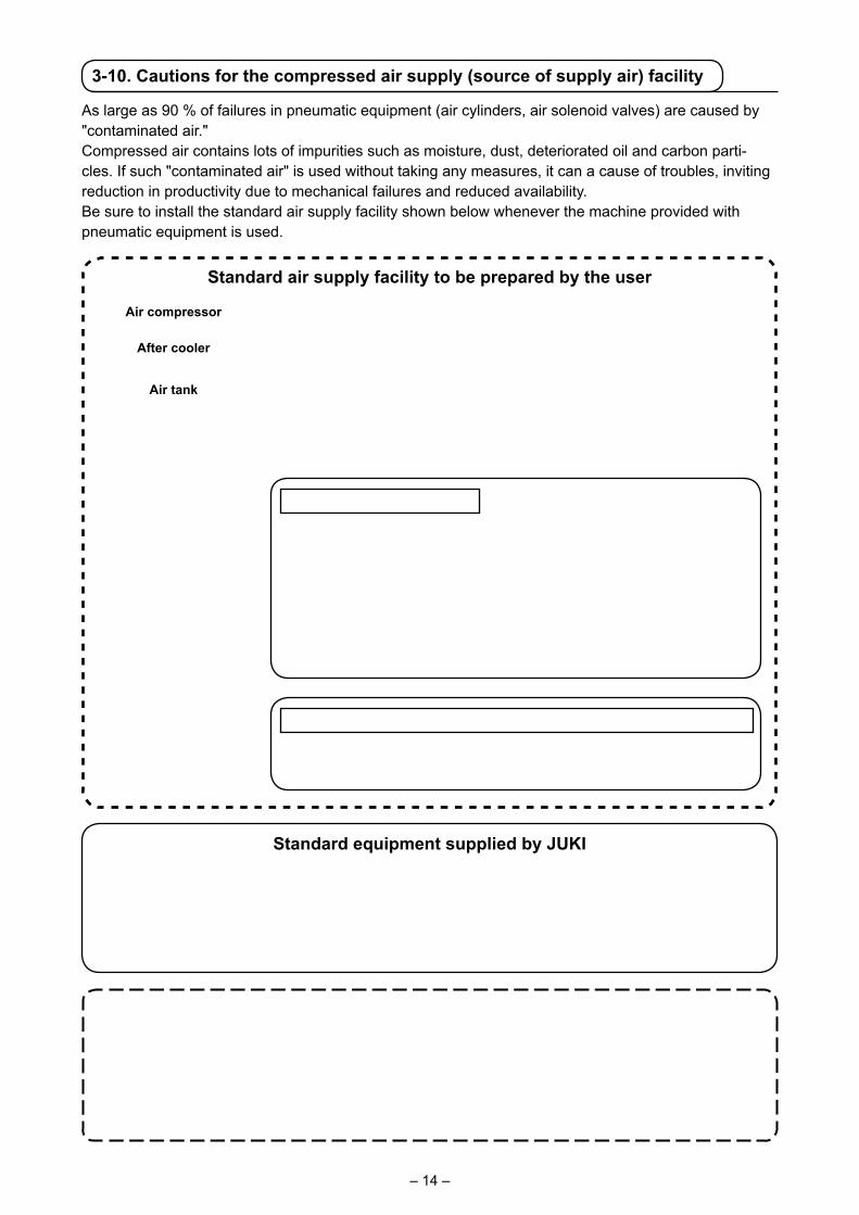
3-10. Cautions for the compressed air supply (source of supply air) facility
As large as 90 % of failures in pneumatic equipment (air cylinders, air solenoid valves) are caused by "contaminated air."Compressed air contains lots of impurities such as moisture, dust, deteriorated oil and carbon parti-cles. If such "contaminated air" is used without taking any measures, it can a cause of troubles, inviting reduction in productivity due to mechanical failures and reduced availability.Be sure to install the standard air supply facility shown below whenever the machine provided with pneumatic equipment is used.
Standard air supply facility to be prepared by the user
Standard equipment supplied by JUKI
Air compressor
After cooler
Air tank
Main line filter
Air dryer
Mist separator
Auto-drain
Auto-drain
Quality of the air supply
When the supply air contains a considerable amount of moisture
Ambient environmentWhen our machine is installed at a place where the temperature greatly changes in the morning and in the evening from that in the daytime or freeze is like to occurIn the aforementioned cases, be sure to install an air dryer.
(Most troubles in the air solenoid valves are caused by carbon.)Be sure to install a mist separator.
When the supply air contains a considerable amount of carbon and dust
Filter regulator
Air solenoid valve
Air cylinder
Cautions for main piping• Be sure to slope main piping by a falling gradient of 1 cm per 1 m in the direction of air flow.• If the main piping is branched off, the outlet port of the compressed air should be pro-
vided at the top part of the piping using a tee in order to prevent drain settling inside the piping from flowing out.
• Auto drains should be provided at all lower points or dead ends in order to prevent the drain from settling in those parts.
– 15 –
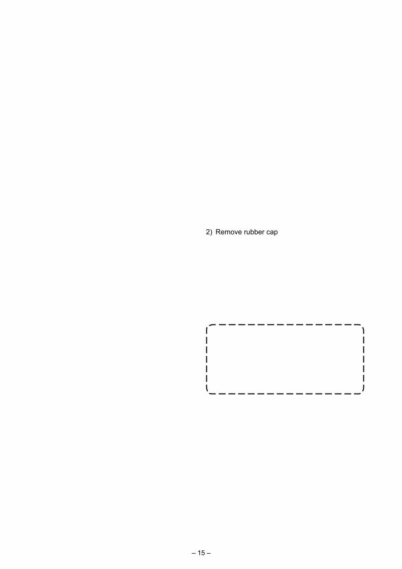
2) Remove rubber cap ❷ . Add JUKI New Defrix Oil No. 2 supplied with the unit into the oil tank. The oil surface in the oil tank must not exceed upper line A.
3) Periodically check to make sure that the oil surface in the oil tank remains between lower line B and upper line A while using the sewing machine. Fill there with oil using the oiler sup-plied with the machine as accessories when oil is short.
The oil tank which is filled with oil is only for lubricating to the hook por-tion. It is possible to reduce the oil amount when the number of rotation used is low and the oil amount in the hook portion is excessive. (Refer to "III-1-6. Amount of oil supplied to the hook" p.119 .)
1. Do not lubricate to the places other than the oil tank and the hook of Caution 2 below. Trouble of components will be caused.
2. When using the sewing machine for the first time or after an extended period of disuse, use the machine after lubricating a small amount of oil to the hook portion. In addition, use the sewing machine for sewing after having it run idle for approximately two min-utes at 1,000 sti/min. (Refer to "III-1-2. Adjusting the needle-to-shuttle relation" p.116 .)
Keep hook section safety cover ❶ closed while the sewing machine is in operation.
4. PREPARATION OF THE SEWING MACHINE
4-1. Lubrication
WARNING : Turn OFF the power before starting the work so as to prevent accidents caused by abrupt start or
the sewing machine.
1) Open hook section safety cover ❶ .
❶
❸
A
❷
B
When you use the sewing machine for the first time after the purchase, lubricate hook race sur-face ❸ until a drop of oil can be observed.
– 16 –
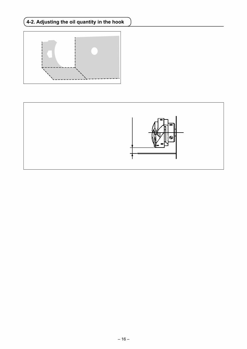
4-2. Adjusting the oil quantity in the hook
① Paper for checking the oil quantity (oil spots) ② Position at which the oil quantity (oil spots) is checked
Oil-spots checking paper
3 to
10
mm
25 m
m
70 mm
* When carrying out the following work described in step 2), take added care not to allow your fingers to come in contact with the hook.
1) In the case the machine head is cold, run it idle for approximately three minutes. (Low-speed opera-tion)
2) Insert a sheet of paper for checking the oil quantity (oil spots) in the check position while the sewing machine is in operation.
3) Check to make sure that the oil surface in the oil tank is at the level between the upper and lower lines.
4) Check the oil quantity (oil spots) for five seconds. (Measure with a watch.)
(1) Checking the oil quantity in the hook
Fit against the wall
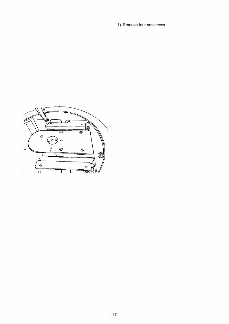
1) Loosen setscrews ❶ (right and left). Detach oil shield ❷ .
At this time, do not attempt to forcibly remove the oil shield. Before removing the oil shield, turn the pulley until the needle stops at its up-per end. Then, remove the oil shield.
2) Turn the hook section so that it faces the front.❷
❶
– 17 –
1) Remove four setscrews ❷ of round table ❶ . Detach round table ❶ .
2) Turn oil quantity adjustment screw ❸ clockwise A until it is fully tightened.
3) Turn the screw counterclockwise B by half.4) The oil quantity (oil spots) is increased by
turning oil quantity adjustment screw ❸ coun-terclockwise B or is decreased by turning it clockwise A.
Carry out the adjustment in the following cases. a. Decrease the hook oil quantity when the oil in
the oil tank at the bed side reduces quickly. b. Decrease the hook oil quantity when the quan-
tity of oil splashing from the hook is large or when oil leaks from the hook cover.
c. Increase the hook oil quantity when the hook generates a large noise.
d. Increase the hook oil quantity if the needle thread is not adequately drawn up due to the oil shortage.
5) After the adjustment of oil quantity, attach round table ❶ in place and fix with four set-screws ❷ .
(2) Adjusting the hook oil quantity (oil spots)
(3) Sample of proper quantity of hook oil (oil spots)
Proper quantity Oil splashing from the hook
1 to 2 mm
1) The state shown in the figure represents the proper quantity of oil (oil spots). Adjustment may be required depending on the sewing pro-cess. However, it is important not to excessive-ly increase/decrease the oil quantity. (Smaller quantity of oil = Hook seizure (hook becomes hot); Larger quantity of oil = Oil stains on the sewn products)
2) Check the oil quantity (oil spots) three times (with three sheets of paper).
❶
❷
AB
❸
– 18 –
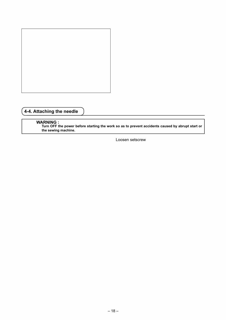
4-4. Attaching the needle
WARNING : Turn OFF the power before starting the work so as to prevent accidents caused by abrupt start or
the sewing machine.
Loosen setscrew ❶. Insert needle ❷ into the hole in needle bar until it will go no further while facing its long groove toward the frame. Then, tighten setscrew ❶.
When tightening setscrew ❶ , be sure to use the screwdriver (Part No. : 40032763) supplied as accessories.Do not use L-shaped hexagon wrench key. There is a danger of breaking set-screw ❶ .
❶
❷
1.5 mm
4-3. Checking the emergency stop switch
When the red button of emergency stop switch ❶ is strongly pressed as far as it goes, the switch is placed in its ON state. When the button is turned clockwise, the switch is placed in its OFF state.Check to be sure that emergency stop switch ❶ is in its OFF state.If emergency stop switch ❶ is in its ON state, the operation panel screen will not light up even if the power switch is turned ON.
Emergency stop switch OFF state
Emergency stop switch ON state
❶
– 19 –
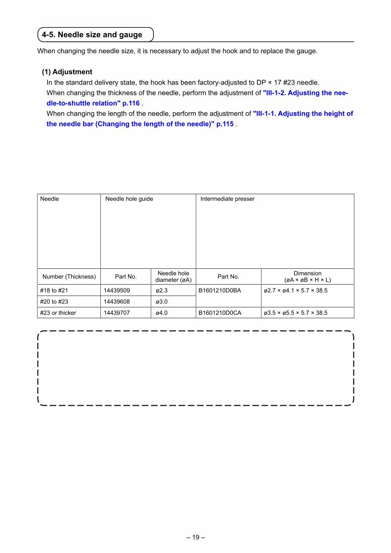
Needle Needle hole guide Intermediate presser
Number (Thickness) Part No. Needle hole diameter (øA) Part No. Dimension
(øA × øB × H × L)
#18 to #21 14439509 ø2.3 B1601210D0BA ø2.7 × ø4.1 × 5.7 × 38.5
#20 to #23 14439608 ø3.0
#23 or thicker 14439707 ø4.0 B1601210D0CA ø3.5 × ø5.5 × 5.7 × 38.5
4-5. Needle size and gauge
When changing the needle size, it is necessary to adjust the hook and to replace the gauge.
(1) Adjustment In the standard delivery state, the hook has been factory-adjusted to DP × 17 #23 needle. When changing the thickness of the needle, perform the adjustment of "III-1-2. Adjusting the nee-
dle-to-shuttle relation" p.116 . When changing the length of the needle, perform the adjustment of "III-1-1. Adjusting the height of
the needle bar (Changing the length of the needle)" p.115 .
When the adjustment of hook and driver is not fit to the thickness of the needle, sewing trou-bles such as stitch skipping and the like or abrasion of the blade point of hook will be caused.
(2) Gauge When changing the needle size, replace the gauge with the optional gauge of the correspondence table.
1. The table above describes the typical optional gauges. For the other special gauges, ask our sales distributors. 2. When using the gauge that is not fit for the thickness of the needle, needle breakage,
abrasion of components such as inner hook and the like, sewing trouble such as stitch skipping and the like will be caused.Example : When sewing the sports shoes with a big size needle guide or inner hook
presser, needle thread loop becomes unstable and stitch skipping or thread breakage may occur.
øA
L
H
øB
øA
– 20 –
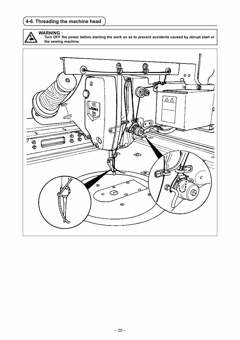
4-6. Threading the machine head
WARNING : Turn OFF the power before starting the work so as to prevent accidents caused by abrupt start or
the sewing machine.
– 21 –
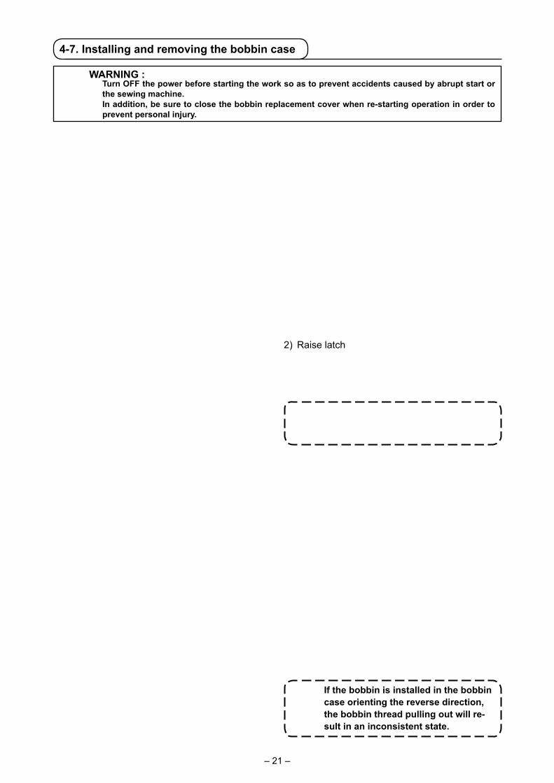
If the bobbin is installed in the bobbin case orienting the reverse direction, the bobbin thread pulling out will re-sult in an inconsistent state.
4-7. Installing and removing the bobbin case
WARNING : Turn OFF the power before starting the work so as to prevent accidents caused by abrupt start or
the sewing machine. In addition, be sure to close the bobbin replacement cover when re-starting operation in order to
prevent personal injury.
2) Raise latch ❸ of bobbin case ❷ , and remove the bobbin case.
3) When entering bobbin case, insert it with the latch tilted until "click" sounds.
If bobbin case ❷ is not adequately fit-ted in the hook, it can drop off the hook or needle can break during sewing.
A 1) When button A is pressed, the turning section rotates to allow the hook to face the front face and bobbin replacement cover ❶ to open.
4-8. Installing the bobbin
WARNING : Turn OFF the power before starting the work so as to prevent accidents caused by abrupt start or
the sewing machine.
1) Set the bobbin ❶ into bobbin case ❷ in the direction shown in the figure.
2) Pass the thread through thread slit ❸ of bob-bin case ❷ , and pull the thread as it is. By so doing, the thread will pass under the tension spring and be pulled out from thread hole ❹ .
3) Pass the thread under bobbin thread guide ❺ and draw the thread by 4 cm out from the bob-bin thread guide.
❷
❸
❶
4 cm
❸
❷❶
❹
❺
– 22 –
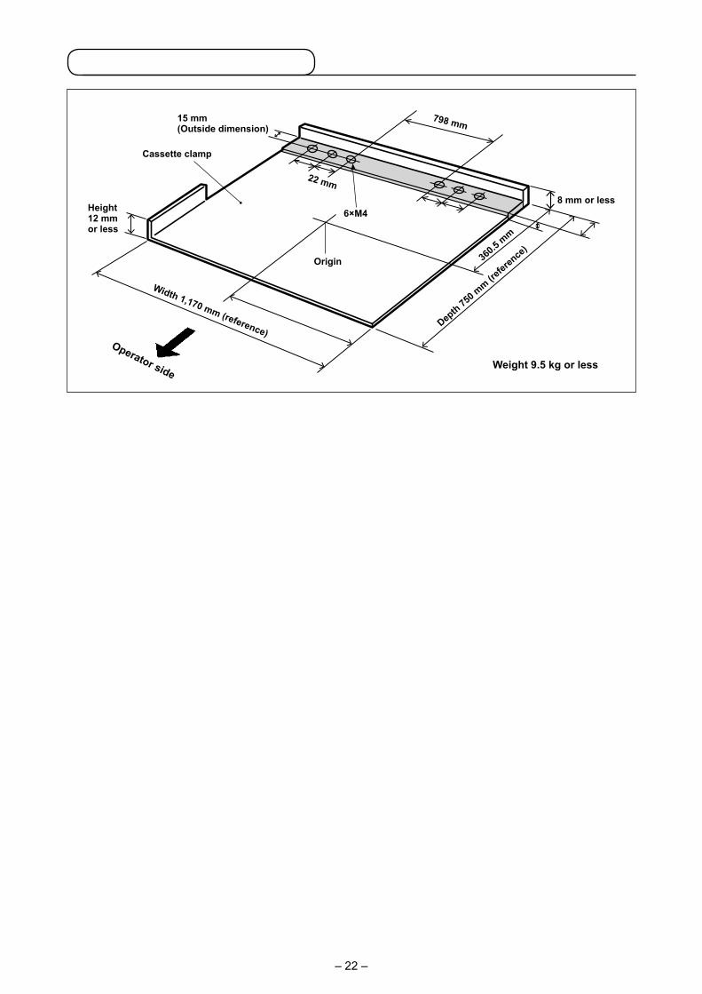
Cassette clamp
Operator sideWeight 9.5 kg or less
Width 1,170 mm (reference)Dep
th 750 m
m (refer
ence
)
Height12 mm or less
360.5
mm
22 mm
6×M4
Origin
798 mm15 mm(Outside dimension)
8 mm or less
2) Stick a piece of Teflon sheet (option: 40123146) or the like on the undersurface of cassette clamp.
1. If a piece of Teflon sheet or the like is not stuck on the undersurface of cassette clamp, the top surface of throat plate can get dirty to cause stains on the sewing material.
The Teflon sheet is a consumable part. It is necessary therefore periodically inspect it and change it with a new one if it has worn out.
2. Clean the undersurface and material retaining surface of cassette clamp and the top surface of throat plate auxiliary cover before use. After the cleaning, check to be sure that the aforementioned sections are free from dirt. Then, start using the sewing ma-chine.
1) The cassette clamp is separately available by a special order. In the case the customer prepares a cassette clamp, the cassette clamp which is shown in the above
figure must be prepared.
585 mm (reference)
22 mm
22 mm
22 mm
26 mm
Height 5.5 mm(Chuck plate mounting base, height)
The sewing area has been factory set to the area (1,000 x 600) as shown in the figure at the time of shipment.
[Sewing area]
Sewing area
Origin
1,000mm
300m
m30
0mm
In the case of using the sewing area that is 600 mm in longitudinal direc-tion, the cassette clamp may protrude the throat plate auxiliary cover when the material is fed in Y direction. So, be careful.
4-9. Preparing the cassette clamp

– 23 –
3) Temporarily fix chuck plates (40181516) ❷ at the 782-mm pitch positions of cassette clamp ❶ with setscrews and washers. (Chuck plates, setscrews and washers are packed in the accessory box.)
4) While fitting chuck plate ❷ against chuck ❸ , attach the cassette clamp in place. Then, securely fix chuck plates ❷ with setscrews.
To detach the cassette clamp, press eject switch ❹ (blue).5) Attach and detach the cassette clamp several time in repetition to check whether it can be complete-
ly attached in place. After attaching the cassette clamp in place, move it back and forth to check whether there is a back-
lash.
❷
❸
❷
❶
❹
Chuck plate mounting pitch782 mm
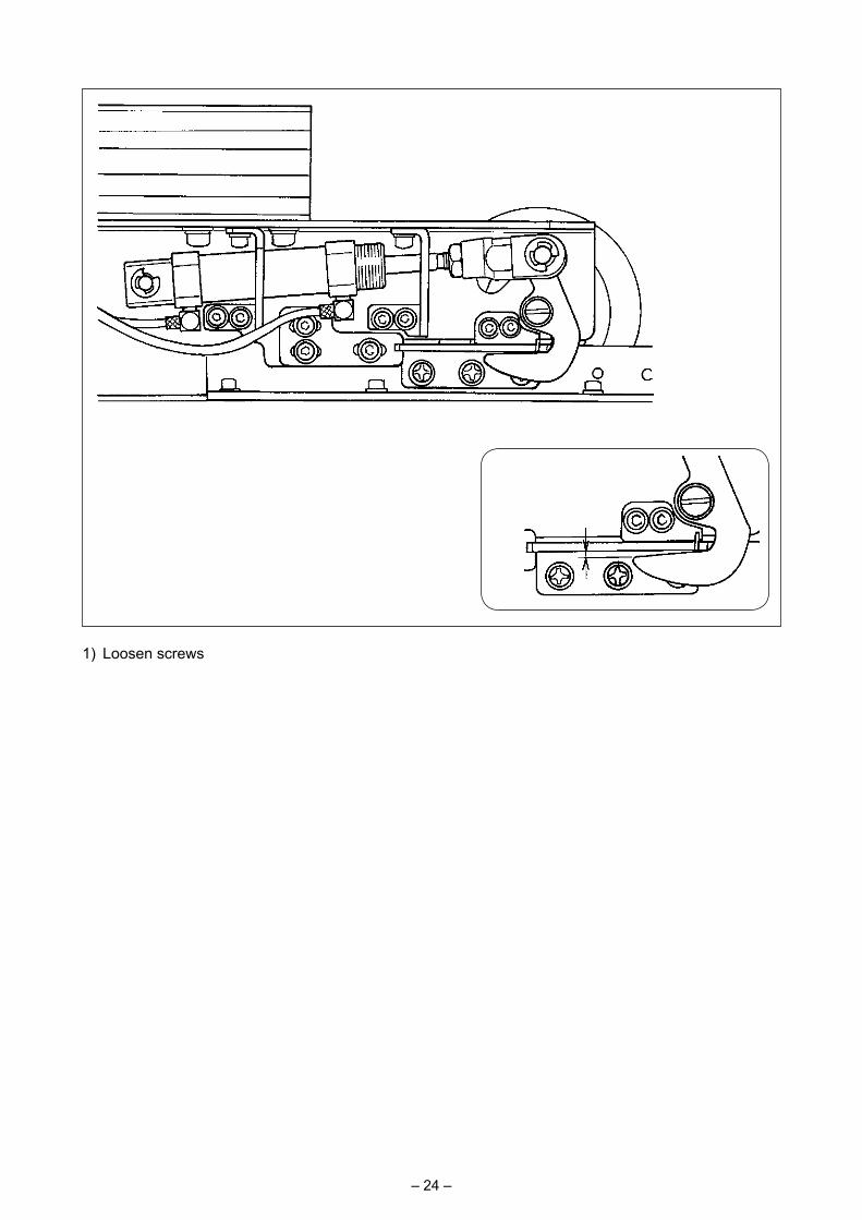
– 24 –
1) Loosen screws ❻ (3 pieces). Press chuck plate bracket A ❺ against chuck plate ❷ of the cassette clamp and fix with screw ❻ .
Adjust the position of chuck plate bracket A ❺ also on the opposite side in the same manner. At this time, adjust so that right and left chuck plates ❷ and chuck plate brackets A ❺ are symmetrically positioned.
2) Then, pressing cylinder knuckle ❼ toward the releasing side, loosen screws ❾ (2 pieces) of chuck plate bracket B ❽ . Adjust the positional relationship between chuck plate ❷ and chuck ❸ so that they are positioned as illustrated in Fig. I.
Adjust, by pressing chuck plate bracket B ❽ in the direction of the arrow, so that a clearance of 0.5 to 1 mm is provided in section B when the chuck is aligned with the chuck plate at section A. Then, fix the chuck plate B with screws ❾ .
* Apply JUKI Grease A to the contact section indicated in a dotted circle in Fig. I.
[In the case there is a backlash]
Releasing side
❼
❽❾ ❸❺❻ ❷
0.5 to 1 mm
❽Fig. I ❾
B
A

– 25 –
4-10. Adjusting the thread tension
If thread tension controller No. 1 ❶ is turned clockwise, the length of remaining thread on the needle after thread trimming will be shorter. If it is turned counterclockwise, the length will be longer.Shorten the length to an extent that the thread is not slipped off.Adjust needle thread tension from the operation panel and bobbin thread tension with ❷.
[Adjusting the needle thread tension]
1) Select THREAD TENSION button
A in the sewing screen.2) Set needle thread tension with SCROLL
button B. There is a setting range of 0 to 200. When the set value is increased, the tension becomes higher.
* When the set value is 50 at the time of standard delivery, the thread tension is adjusted to 2.35N (spun thread #50). (When thread tension No. 1 is released)
❶
❷
Longer
Shorter
A B

– 26 –
1. When raising the intermediate presser height, turn the pulley by hand to lower the needle bar, and confirm that the needle bar does not interfere with the intermediate presser.
2. Take care not to allow your hands and fingers to be caught in the cassette clamp or the intermediate presser.
1. Setting range of the intermediate presser is up to the standard of 3.5 mm. However, when using DP × 17 needle for H type or the like, the setting range can be
changed up to max. 7 mm with memory switch . 2. When increasing the height of intermediate presser or making the needle size thicker,
confirm the clearance between the wiper and the components. Wiper cannot be used unless the clearance is secured. In this case, turn OFF the wiper switch, or change the set value of memory switch .
(Wiper is optionally available.)
4-11. Intermediate presser height
Press INTERMEDIATE PRESSER SETTING button A and ad-just with TEN keys B so that the clearance between the bottom end of intermediate presser and the cloth is 0.5 mm (thickness of thread used).
A
B
4-12. Adjusting the thread take-up spring
1) Adjusting the stroke Loosen setscrew ❷ , and turn thread tension asm.
❸ . Turning it clockwise will increase the moving
amount and the thread drawing amount will increase.
2) Adjusting the pressure To change the pressure of the thread take-
up spring ❶ , insert a thin screwdriver into the slot of thread tension post ❹ while screw ❷ is tightened, and turn it. Turning it clockwise will increase the pressure of the thread take-up spring. Turning it counterclockwise will de-crease the pressure.
0.5 mm
❶
❹
❸
Decrease
Increase
❷

– 27 –
Take care not to allow your hands and fingers in the intermediate presser and cassette clamp when they move. In addition, take care not to allow your hands and fingers to be hit by the intermediate presser and cassette clamp since they move at a high speed.
5. OPERATION OF THE SEWING MACHINE
5-1. Sewing
WARNING : Take added care not to press a wrong button in order to prevent an accident caused by sudden
start of the sewing machine.
When the eject switch ❹ is pressed or the sewing machine completes sewing, the cassette clamp is ejected to the front of the device. If you place an article or your hand(s) on the top surface of table, the cassette clamp can accidentally come in contact with the article or your hand(s) when it is ejected. So, be careful.
1) Place the sewing material on the sewing machine.2) Press power switch ❶ .3) When both of two start switches ❷ are pressed simultaneously, the intermediate presser comes
down and the sewing machine starts sewing.4) Press pause switch ❸ (white) to stop the sewing machine temporarily. Refer to "II-2-9. How to use temporary stop" p.46 for how to use it. * When eject switch ❹ (blue) is pressed, the cassette clamp is ejected to the front of the device.5) Once the sewing machine completes sewing, the needle tip returns to the sewing start position and
the intermediate presser goes up. Then, the cassette clamp is ejected to the front of the device.6) To stop the sewing machine at an emergency, press emergency stop switch ❺ .
❺
❸
❶
❹
❷
– 28 –
1. PREFACE
* The medium supplied with the unit as an accessory contains the service patterns shown in the table given below.
1) Kind of sewing data handled with IP-420
2) Using the data (M3 data) of AMS-210D series with AMS-251 There are two ways to use M3 data with AMS-251.
① Reading by using IP-420 Use PC (personal computer) and copy file (¥AMS¥AMS00xxx.M3) of M3 from floppy disk of AMS-D
to ¥AMS of media. Insert the media to IP-420, and select Pattern No.xxx from M3 data.
② Changing to vector format data using PM-1 Change to the vector format data with PM-1. (For the details, refer to Help of PM-1.) Copy the changed vector format data to ¥VDATA folder of the media. Insert the media to IP-420 and select Pattern No.
II. OPERATION SECTION (WITH REGARD TO THE PANEL)
KindArea
H
10060
ø 60 Pitch 3.0 mmPattern No. 110
Pattern name Description
Users' pattern Pattern that can be stored in the body.Max. 999 patterns can be registered.
Vector format data File that extension is ".VDT"Read from media. Max. 999 patterns can be used.
M3 data Pattern data of AMS-210D seriesUsed by copying from floppy disk of AMS-210D series to media. Max. 999 patterns can be used.
Sewing standard format File that extension is ".DAT"Read from media. Max. 999 patterns can be used.
– 29 –
1. When the inserting direction is wrong, panel or media may be damaged. 2. Do not insert any item other than the CompactFlash (TM). 3. The media slot in the IP-420 accommodates to the CompactFlash (TM) of 2 GB or less. 4. The media slot in the IP-420 supports the FAT16 which is the format of the Compact-
Flash (TM). FAT32 is not supported. 5. Be sure to use the CompactFlash (TM) which is formatted with IP-420. For the formatting
procedure of the CompactFlash (TM), see "II-2-28. Performing formatting of the media" p.91 .
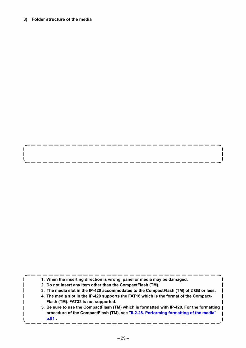
3) Folder structure of the media Store each file in the directories below of the media.
Data that are not stored in the directories above cannot be read. So, be careful.
Store M3 data.
Vector format data : Store in ¥VDATA.
VDATA
Store vector format data.
AMS
VD00 . VDT
SD00 . DAT
SD00 . DAT
AMS0 . M3
AMS0 . M3
VD00 . VDT
SDATA
Store sewing standard data.
M3 data : Store in ¥AMS.
Sewing standard format : Store in ¥SDATA.
4) CompactFlash (TM)
1) Turn the label side of the CompactFlash(TM) to this side (place the notch of the edge to the rear. ) and insert the part that has a small hole into the panel.
2) After completion of setting of the media, close the cover. By closing the cover, it is possible to access. If the media and the cover come in contact with each other and the cover is not closed, check the following matters.・ Check that the media is securely pressed
until it goes no further.・ Check that the inserting direction of the
media is proper.
Media
■ Inserting the CompactFlash (TM)
Media drive

– 30 –
1) Hold the panel by hand, open the cover, and press the media ❷ removing lever ❶ . The media is eject.
When the lever ❶ is strongly pressed, the media ❷ may be broken by pro-truding and falling.
2) When the media ❷ is drawn out as it is, re-moving is completed.
5) USB port■ Inserting a device into the USB port
■ Removing the CompactFlash (TM)
■ Disconnecting a device from the USB port
Slide the top cover and insert the USB device into the USB port. Then, copy data to be used from the USB device onto the main body. After completion of copying the data, remove the USB device.
Remove the USB device. Put the cover back in place.
Cautions when using the media • Do not wet or touch it with wet hands. Fire or electric shock will be caused. • Do not bend, or apply strong force or shock to it.• Never perform disassembling or remodeling of it.• Do not put the metal to the contact part of it. Data may be disappeared.• Avoid storing or using it in the places below. Place of high temperature or humidity / Place of dew condensation / Place with much dust / Place where static electricity or electrical noise is likely to occur
To protect the USB terminal, do not perform sewing by 10 times or more with the USB thumb drive connected to the sewing machine.
❶
❷

– 31 –
① Precautions to be taken when handling USB devices • Do not leave the USB device or USB cable connected to the USB port while the sewing machine is
in operation. The machine vibration can damage the port section resulting in loss of data stored on the USB device or breakage of the USB device or sewing machine.
• Do not insert/remove a USB device during reading/writing a program or sewing data. It may cause data breakage or malfunction. • When the storage space of a USB device is partitioned, only one partition is accessible. • Some type of the USB device may not be properly recognized by this sewing machine. • JUKI does not compensate for loss of data stored on the USB device caused by using it with this
sewing machine. • When the panel displays the communication screen or pattern data list, the USB drive is not recog-
nized even if you insert a medium into the slot. • For USB devices and media such as CF cards, only one device/medium should be basically con-
nected/inserted to/into the sewing machine. When two or more devices/media are connected/insert-ed, the machine will only recognize one of them. Refer to the USB specifications.
• Insert the USB connector into the USB terminal on the IP panel until it will go no further. • Do not turn the power OFF while the data on the USB flash drive is being accessed.
② USB specifications• Conform to USB 1.1 standard• Applicable devices *1 ��� Storage devices such as USB memory, USB hub, FDD and card reader• Not-applicable devices �� CD drive, DVD drive, MO drive, tape drive, etc.• Format supported ����� FD (floppy disk) FAT 12
Others (USB memory, etc.), FAT 12, FAT 16, FAT 32• Applicable medium size � FD (floppy disk) 1.44MB, 720kB
Others (USB memory, etc.), 4.1MB ~ (2TB) • Recognition of drives ��� For external devices such as a USB device, the device which is recog-
nized first is accessed. However, when a medium is connected to the built-in media slot, the access to that medium will be given the highest priority. (Example: If a medium is inserted into the media slot even when the USB memory has already been connected to the USB port, the me-dium will be accessed.)
• Restriction on connection ��Max. 10 devices (When the number of storage devices connected to the sewing machine has exceeded the maximum number, the 11th storage device and beyond will not be recognized unless they are once discon-nected and re-connected.)
• Consumption current ��� The rated consumption current of the applicable USB devices is 500 mA at the maximum.
*1: JUKI does not guarantee operation of all applicable devices. Some device may not operate due to a compatibility problem.
– 32 –
2. WHEN USING IP-420
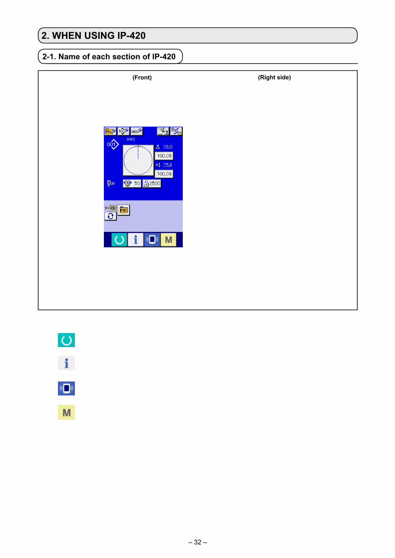
2-1. Name of each section of IP-420
(Front) (Right side)
①
③
②
④ ⑤
① Touch panel・LCD display section
② READY key → Changeover of the data input screen and the sewing screen can be performed.
③ INFORMATION key → Changeover of the data input screen and the information screen can be performed.
④ COMMUNICATION key → Changeover of the data input screen and the communication screen can be performed.
⑤ MODE key → Changeover of the data input screen and the mode changeover screen which
performs various detail settings can be performed.⑥ Contrast control ⑦ Brightness control⑧ CompactFlash (TM) eject button⑨ CompactFlash (TM) slot⑩ Cover detection switch⑪ Connector for external switch⑫ Connector for control-box connection
⑪
⑦
⑫
⑧
⑨
⑥
⑩

– 33 –
2-2. Buttons to be used in common
The buttons which perform common operations in each screen of IP-420 are as follows :
CANCEL button → This button closes the pop-up screen. In case of the data change screen, the data being
changed can be cancelled.
ENTER button → This button determines the changed data.
UP SCROLL button → This button scrolls the button or the display in the upward direction.
DOWN SCROLL button → This button scrolls the button or the display in the downward direction.
RESET button → This button performs the release of error.
NUMERAL INPUT button → This button displays ten keys and input of numerals can be performed.
CHARACTER INPUT button → This button displays the character input screen. → Refer to "II-2-14. Naming users’ pattern" p.55 .
RESSER LOWERING button → Presser is lowered, and the presser lowering screen is displayed. To lift presser, press presser lift button displayed in the presser lowering screen.
Bobbin replacement button → Bobbin replacement is carried out. → Refer to "I-4-7. Installing and removing the
bobbin case" p.21 .

– 34 –
1. In the case an exclusive cassette clamp is used, check the pattern shape for the pur-pose of confirmation. If the pattern lies off the cassette clamp, the needle can interfere with the cassette clamp during sewing causing danger such as needle breakage.
2. When turning OFF the power without pressing READY key , the set value of "Pat-
tern No.", "X enlargement/reduction ratio", "Y enlargement/reduction ratio", "Max. sew-ing speed", "Thread tension" or "Intermediate presser height" is not stored in memory.
① Turn ON the power switch When the power is turned ON first, the language selection
screen is displayed. Set the language you use. (It is possible to change with Memory switch .)
When ending the selection screen with CANCEL button
or ENTER button without performing the
language selection, the language selection screen is displayed whenever the power is turned ON.
② Select the pattern No. you desire to sew. When the power is turned ON, the data input screen is dis-
played. Pattern No. button A whichs selected at present is displayed in the center of the screen. Press the button to se-lect the sewing shape. For selecting procedure of the sewing shape, refer to "II-2-5. Performing sewing shape selection" p.39 .
When READY key B is pressed, the back color of LCD
display is changed to green, and the sewing machine is set to the sewing possible state.
2-3. Basic operation of IP-420
A
B
③ Start sewing. Start sewing referring to "I-5-1. Sewing" p.27 .
* For the screen, refer to "II-2-4. LCD display section at the time of sewing shape selection" p.35 .
– 35 –
B C D E
I
L
J
K
M
P
A
F
H
N
O
G
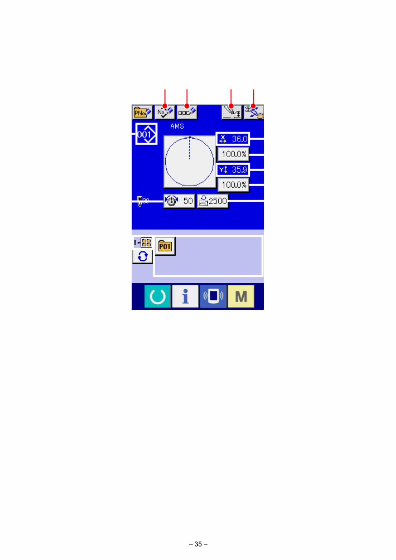
(1) Sewing shape data input screen
2-4. LCD display section at the time of sewing shape selection
Button and display Description
A PATTERN BUTTON NEW REGISTER button
Pattern button new register screen is displayed.→ Refer to "II-2-15. Performing new register of pattern button" p.56 .
B USERS’ PATTERN NEW REGISTER button
Users’ pattern new register screen is displayed.→ Refer to "II-2-13. Performing new register of users’ pattern" p.54 .
C PATTERN BUTTON NAME SETTING button
Pattern button name input screen is displayed.→ Refer to "II-2-14. Naming users’ pattern" p.55 .
D INTERMEDIATE PRESSER SETTING button
Intermediate presser is lowered and the intermediate presser reference value change screen is displayed.→ Refer to "II-2-6. Changing item data" p.41 .
E BOBBIN REPLACEMENT button
Bobbin replacement is carried out.→ Refer to "I-4-7. Installing and removing the bobbin case" p.21 .
– 36 –
Button and display Description
F SEWING SHAPE NO. display
Kind and No. of the sewing shape being selected at present is displayed.There are 4 kinds below of the kinds of sewing shape.
: Users' pattern
: Vector format data
: M3 data
: Sewing standard format
* Be sure to use the media that has been formatted with IP-420. For the formatting procedure of the media, refer to "II-2-28. Performing
formatting of the media" p.91 .
G SEWING SHAPE SELECTION button
Sewing shape being selected at present is displayed on this button and when the button is pressed, the sewing shape selection screen is displayed.→ Refer to "II-2-5. Performing sewing shape selection" p.39 .
H NEEDLE THREAD TENSION SETTING button
Needle thread tension value which is set to the pattern data being selected at present is displayed on this button and when the button is pressed, the item data change screen is displayed.→ Refer to "II-2-6. Changing item data" p.41 .
I X ACTUAL SIZE VALUE display
Actual size value in X direction of sewing shape being selected at present is displayed.When the actual size value input is selected by setting memory switch , X actual size value setting button is displayed.→ Refer to "II-2-6. Changing item data" p.41 .
J X SCALE RATE SETTING button
Scale rate in X direction of sewing shape being selected at present is displayed on this button.When the scale input is set to non-selection by setting memory switch , the button goes out and the X scale is displayed.→ Refer to "II-2-6. Changing item data" p.41 .
K Y ACTUAL SIZE VALUE display
Actual size value in Y direction of sewing shape being selected at present is displayed.When the actual size value input is selected by setting memory switch , Y actual size value setting button is displayed.→ Refer to "II-2-6. Changing item data" p.41 .
L Y SCALE RATE SETTING button
Scale rate in Y direction of sewing shape being selected at present is displayed on this button. When the scale input is set to non-selection by setting memory switch , the button goes out and the Y scale is displayed.→ Refer to "II-2-6. Changing item data" p.41 .
M MAX. SPEED LIMITATION Maximum speed limitation which is set at present is displayed on this button and when the button is pressed, the item data change screen is displayed. (However, maximum speed limitation which is displayed is different from the maximum number of revolutions in the pattern.)→ Refer to "II-2-6. Changing item data" p.41 .
N FOLDER NO. display Pattern register button which is displayed indicates the folder No. which has been stored.
O FOLDER SELECTION button
Folders to display the patterns are displayed in order.
P PATTERN REGISTER button
PATTERN REGISTER buttons stored in N FOLDER NO display are displayed.→ Refer to "II-2-15. Performing new register of pattern button" p.56 .* This button is not displayed unless the new register to the pattern button is
performed.
– 37 –
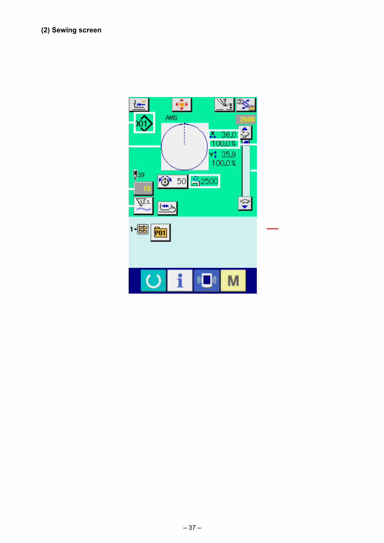
(2) Sewing screen
R
AB C D
PNO
M
Q
S
E
G
J
I
H
K
F
L
Button and display Description
A PATTERN BUTTON MOVE button
The pattern button move screen is displayed.→ Refer to "II-2-10. When setting of sewing product is difficult because of interruption of needle tip" p.48 .
B RETURN TO ORIGIN button
This button returns the presser to the start of sewing and raises the presser at the time of temporary stop.
C INTERMEDIATE PRESSER SETTING button
Intermediate presser is lowered and the intermediate presser reference value change screen is displayed.→ Refer to "II-2-6. Changing item data" p.41 .
D BOBBIN REPLACEMENT button
Bobbin replacement is carried out.→ Refer to "I-4-7. Installing and removing the bobbin case" p.21 .
– 38 –
Button and display Description
E SEWING SHAPE NO. display
Kind and No. of the sewing shape being selected at present is displayed.There are 4 kinds below of the kinds of sewing shape.
: Users' pattern
: Vector format data
: M3 data
: Sewing standard format
* Be sure to use the media that has been formatted with IP-420. For the formatting procedure of the media, refer to "II-2-28. Performing
formatting of the media" p.91 .
F SEWING SHAPE display Sewing shape being selected at present is displayed.
G NEEDLE THREAD TENSION SETTING button
Needle thread tension value which is set to the pattern data being selected at present is displayed on this button and when the button is pressed, the item data change screen is displayed.→ Refer to "II-2-6. Changing item data" p.41 .
H TOTAL NUMBER OF STITCHES OF SEWING SHAPE display
Total number of stitches of the sewing shape being selected at present is displayed.
I COUNTER VALUE CHANGE button
Existing counter value is displayed on this button.When the button is pressed, the counter value change screen is displayed.→ Refer to "II-2-12. Using counter" p.51 .
J COUNTER CHANGE OVER button
The counter display can be changed over among the sewing counter, No. of pcs. counter and bobbin counter.→ Refer to "II-2-12. Using counter" p.51 .
K STEP SEWING button Step sewing screen is displayed. Checking of the pattern shape can be performed.→ Refer to "II-2-7. Checking pattern shape" p.43 .
L FOLDER NO. display Pattern register button which is displayed indicates the folder No. which has been stored.
M SPEED variable resistor Number of rotations of the sewing machine can be changed.
N X SCALE RATE display Scale rate in X direction of sewing shape being selected is displayed.
O X ACTUAL SIZE VALUE display
Actual size value in X direction of sewing shape being selected is displayed.
P Y ACTUAL SIZE VALUE display
Actual size value in Y direction of sewing shape being selected is displayed.
Q Y SCALE RATE display Scale rate in Y direction of sewing shape being selected is displayed.
R MAX. SPEED LIMITATION display
Maximum speed limitation which is set at present is displayed. However, the display is different from the maximum number of revolutions in the pattern. However, the display is different from the maximum number of revolutions in the pattern.
S PATTERN REGISTER button
Pattern register buttons stored in L FOLDER NO. display are displayed.→ Refer to "II-2-15. Performing new register of pattern button" p.56 .* This button is not displayed in the initial state.

– 39 –
① Display the data input screen. Only in case of the data input screen (blue), the selection of
sewing shape can be performed. In case of the sewing screen
(green), press READY key and display the data input
screen (blue).
② Call the sewing shape selection screen. Press SEWING SHAPE button A and the sewing shape
selection screen is displayed.
2-5. Performing sewing shape selection
③ Select the sewing shape. There are 4 kinds of the sewing shape.
Press SEWING SHAPE SELECTION button B.
④ Determine the kind of sewing shape. There are 4 kinds below of the sewing shape. Select the kind
you desire from among them.
Select the sewing shape you desire from SEWING SHAPE SELECTION buttons E and press ENTER
F button.
The sewing shape list screen corresponding to the kind of sewing shape you selected is displayed.
When button C or D is pressed in this screen, X or Y enlarging/reducing ratio can be changed. For the details, refer to "II-2-6. Changing item data" p.41 .
Be sure to use the media that has been formatted with IP-420.For the formatting procedure of the media, refer to "II-2-28. Performing formatting of the media" p.91 .
A
F
E
BC
D
Pictograph Name Maximum number of patterns
Users' pattern 999
Vector format data 999
M3 data 999
Sewing standard format 999

– 40 –
⑤ Select the sewing shape.
When UP or DOWN SCROLL button G is pressed,
the SEWING SHAPE buttons H are changed over in order.
⑥ Determine the sewing shape.
When ENTER button I is pressed, the sewing shape is
determined and the data input screen is displayed.
When the sewing shape is users' pattern, the screen as A is displayed.
PATTERN NO. SELECTION button J that is registered to users' pattern is displayed. Press the button of PATTERN NO. you desire to select.
When VIEWER button K is pressed, the shape of the
pattern No. selected is displayed and you can confirm it.
H G
J
IK
A

– 41 –
① Display the data input screen. In case of the data input screen, the change of item data
can be changed. In case of the sewing screen (green), press
READY switch to display the data input screen (blue).
* The thread tension and the intermediate presser height can be changed even on the sewing screen.
② Display the item data input screen. When the button of the item data you desire to change is
pressed, the item data input screen is displayed. Item data are 5 items below.
* Thread tension value and intermediate presser reference value will change with every pattern to be selected.
* A Scale rate in X direction and B Scale rate in Y direction can be changed to actual size value input by selection of the memory switch .
* There are two ways below to perform X/Y enlargement/reduction.• The data already read in this data input screen can be repeatedly enlarged or reduced.• X/Y scale rate can be set and read when selecting the pattern. See "II-2-5. Performing sewing
shape selection" p.39 .
* In case of the point sewing, even when increase/decrease of number of stitches is set under Enlargement and reduction function mode, enlargement and reduction can be performed with in-crease/decrease of pitch.
* When X/Y scale rate is individually set in case of circle or arc, or X/Y enlargement and reduction are repeated, the sewing is changed to point sewing and the shape may not be kept. Enlargement and reduction can be performed by increase/decrease of pitch. In this case, set and read X/Y scale rate in the pattern list screen.
* Max. input range and initial value of max. speed limitation D are determined with memory switch .
* Change of the intermediate presser height cannot be performed immediately after turning ON the power or immediately after moving from the main unit input. Use the machine after pressing READY
key and performing the origin retrieval.
2-6. Changing item data
Item range Input range Initial value
A Scale rate in X direction 1.0 to 400.0 (%) 100.0 (%)
B Scale rate in Y direction 1.0 to 400.0 (%) 100.0 (%)
C Thread tension 0 to 200 Pattern set value
D Max. speed limitation 200 to 2,500 (sti/min) 2,500 (sti/min)
E Intermediate presser height 0.0 to 3.5 (mm) (Max 0.0 to 7.0 (mm)) Pattern set value
WARNING : Be sure to confirm the shape of pattern after the change of X/Y enlargement/reduction ratio. There
may be a dangerous case such as needle breakage by interference of needle with the presser or the like according to the set value.
A
BDC
E

– 42 –
For example, input X scale rate.Press A to display the item data input screen.
③ Input the data. Input the value you desire with ten keys and + / – keys F.
④ Determine the data.
When ENTER button G is pressed, the data is deter-
mined. * For the other item data, the data can be changed by the
same operation. * It is possible to input X/Y value of enlargement/reduction
ratio and actual size value with one screen.
1. When turning OFF the power without pressing READY key , the set value of "Pat-
tern No.", "X enlargement/reduction ratio", "Y enlargement/reduction ratio", "Max. sew-ing speed", "Thread tension" or "Intermediate presser height" is not stored in memory.
2. When operation processing cannot be performed since the reduction ratio is excessive-ly small, E045 Pattern data error is displayed.
3. When the scale rate is changed with increase/decrease of number of stitches (pitch is fixed), mechanical control command inputted to the points other than the shape point is deleted.
H
I
When X/Y enlargement/reduction ratio, thread tension, intermedi-ate presser, adding/deleting of thread tension command, or adding/deleting of increase/decrease value of intermediate presser of us-ers’ pattern or media pattern is performed, the pattern kind section becomes change display H.
In case of change display H, the change confirmation screen is displayed at the time of the change of pattern.
When ENTER button I is pressed, the information on the
current pattern is invalidated and the pattern No. is changed.To store the changed pattern, refer to "II-2-13. Performing new register of users’ pattern" p.54 .
G
F

– 43 –
① Display the sewing screen. Display the data input screen (blue) and press READY key
A. Then the back-light of LCD changes to green and sewing is possible. When the work clamp is in its upper posi-tion, the work clamp first comes down to its lower position and then moves to the sewing start point.
Be careful not to get your fingers caught between the work clamp and the throat plate.
④ Proceed stitching with the presser lowered. The sewing shape is displayed at the center of the screen. The
current point, sewing start position and sewing end position are respectively represented by (pink circle), (blue dot) and (pink dot).
Check the sewing shape using ONE-STITCH BACKWARD button C and ONE-STITCH FORWARD button D. When two or more commands have been entered, the feed position does not change but the command display A is moved forward and backward. When you keep pressing the ONE-STITCH FORWARD or BACKWARD button, the moving speed increases.
When the COMMAND SEARCH FORWARD button E is pressed, the feed automatically moves to the sewing end position. When the COMMAND SEARCH BACKWARD button
F is pressed, the feed automatically moves to the sew-ing start position.
To stop the feed, press button C, D, E, F, G or H. When INTERMEDIATE PRESSER button G is pressed,
the intermediate presser is raised or lowered. (This button is not displayed when MEMORY switch is set at .)
⑤ Finish checking the shape. When PRESSER INITIAL POSITION button H is
pressed, the work clamp moves to the sewing start position and the screen is restored to the sewing screen. When CAN-CEL button I is pressed, the screen is also restored to the sewing screen. When the work clamp does not rest at the sew-ing start or end position, sewing can be started by depressing the foot switch before sewing shape checking is not completed.
The sewing machine does not start even when the foot switch is depressed with this mode.
② Display the step sewing screen.
When STEP SEWING button B is pressed, the step sewing screen is displayed.
③ Lower the presser with the foot switch.
WARNING : Make sure without fail of the contour of the sewing pattern after selection of the sewing pattern.
If the sewing pattern extends outside the work clamp feet, the needle will interfere with the work clamp.
2-7. Checking pattern shape
A
B
IA
CH
DG
EF

– 44 –
2-8. Performing modification of needle entry point
A
B
L
K
DG
E
H
IA
B J
C
F
(1) Editing the thread tension
Press STEP SEWING button A on the sewing screen to display the step sewing screen.
When it is necessary to move the feed forward or back-ward such as in the case of needle checking, the feed does not move unless the work clamp is lowered. Be sure to check the needle or other relevant operation after having lowered the work clamp.
The sewing shape is displayed at the center of the screen. The current point, sewing start position and sewing end position are respectively represented by (pink circle), (blue dot) and (pink dot).
Press the MODE SELECT button B to select the thread tension mode.
When ONE-STITCH BACKWARD button C or FOR-WARD button D is pressed, the feed (current point ) moves backward or forward by one stitch. When two or more commands have been entered, the feed position does not change but the command display A is moved forward and backward. When you keep pressing the button C or D, the moving speed increases.
Indicated value B is the absolute value (Thread tension value + Thread tension command value).
When COMMAND SEARCH FORWARD button E or
BACKWARD button F is pressed, the feed moves for-ward or backward from the current point to reach the needle entry point where the first thread tension command is found.
To stop the feed, press button C, D, E, F, G or H.
When INTERMEDIATE PRESSER button G is pressed,
the intermediate presser is raised or lowered. (This button is
not displayed when MEMORY switch is set at .)
When PRESSER INITIAL POSITION button H is pressed, the work clamp moves to its origin and the screen is restored to the sewing screen.
When COMMAND DELETE button I is pressed, the
screen for deleting the command as shown in A is displayed.
When J is pressed, the thread tension value increase/decrease input screen is displayed.
Input a desired value on the thread tension value increase/de-crease input screen using numeric keypad and +/– keys K.
When ENTER button L is pressed, the data is con-firmed.

– 45 –
(2) Editing the intermediate presser height
Press STEP SEWING button A on the sewing screen to display the step sewing screen.
The sewing shape is displayed at the center of the screen. The current point, sewing start position and sewing end position are respectively represented by (pink circle), (blue dot) and (pink dot).
Press MODE SELECT button B to select the intermedi-ate presser mode.
When ONE-STITCH BACKWARD button C or FOR-WARD button D is pressed, the feed (current point ) moves backward or forward by one stitch. When two or more commands have been entered, the feed position does not change but the command display A is moved forward and backward. When you keep pressing the button C or D, the moving speed increases.
Indicated value B is the absolute value (Intermediate press-er height value + Intermediate presser height increased/de-creased value).
When COMMAND SEARCH FORWARD button E or BACKWARD button F is pressed, the feed moves for-ward or backward from the current point to reach the needle en-try point where the first intermediate presser command is found.
To stop the feed, press button C, D, E, F, G or H.
When INTERMEDIATE PRESSER button G is pressed, the intermediate presser is raised or lowered. (This button is not displayed when MEMORY switch is set at .)
When PRESSER INITIAL POSITION button H is pressed, the work clamp moves to its origin and the screen is restored to the sewing screen.
When COMMAND DELETE button I is pressed, the screen for deleting the command as shown in A is displayed.
When J is pressed, the intermediate presser height increase/decrease input screen is displayed. Input a desired value on this screen using numeric keypad and +/- keys K.
When ENTER button L is pressed, the data is con-firmed.
1. When checking the needle, or performing the feed forward or backward, the machine fails to work un-less the presser is lowered. Use the machine after lowering the presser.
2. When the intermediate presser rests at its lower po-sition, the movement of the intermediate presser and needle differ depending on the setting of MEMORY switch .
3. When increasing the height of intermediate presser or making the needle size thicker, confirm the clear-ance between the wiper and the components. Wiper cannot be used unless the clearance is secured. In this case, turn OFF the wiper switch, or change the set value of memory switch .
Refer to "II-3. MEMORY SWITCH DATA LIST" p.94 for the memory switch settings.
A
B
IA
B J
DG
E
H
C
F
L
K

– 46 –
When TEMPORARY STOP switch ❶ is pressed during sewing, the sewing machine can be stopped. At this time, the error screen is displayed to inform that the stop switch has been pressed.
(1) To continue performing sewing from some point in sewing
① Release the error.
Press RESET button A to release the error.
② Perform thread trimming.
Press THREAD TRIM button B to perform thread
trimming.
When PRESSER UP button G is pressed, the presser
goes up. Turn OFF the power since the operation afterwards cannot be performed.
When thread trimming is performed, INTERMEDIATE
PRESSER UP/DOWN button C, FEED BACKWARD button D, FEED FORWARD button E, and RETURN TO ORIGIN button F are displayed in the screen.
1. When the presser is raised and the operation is stopped on the way because of the trouble of for-getting to enter the bobbin case or the like, press
PRESSER UP button G and turn OFF the pow-
er.
2. PRESSER UP button G is not displayed when the presser is of pneumatic type.
③ Adjust the presser to the re-sewing position.
When FEED BACK button D is pressed, the presser
returns stitch by stitch and when FEED FORWARD button
E is pressed, it advances stitch by stitch. Move the
presser to the re-sewing position.
④ Re-start the sewing. When the start switch is pressed, the sewing machine re-starts
sewing.
2-9. How to use temporary stop
A
CFED
BG
❶

– 47 –
① Release the error.
Press RESET button A to release the error.
(2) To perform re-sewing from the start
③ Return to the origin.
When RETURN TO ORIGIN button F is pressed, the
pop-up is closed, the sewing screen is displayed and the ma-chine returns to the position of the start of sewing.
④ Perform again the sewing work from the start. When the start switch is pressed, the sewing machine re-starts
sewing.
② Perform thread trimming.
Press THREAD TRIM button B to perform thread trim-ming.
When PRESSER UP button G is pressed, the presser goes up. Turn OFF the power since the operation afterwards cannot be performed.
When thread trimming is performed, INTERMEDIATE
PRESSER UP/DOWN button C, FEED BACKWARD button D, FEED FORWARD button E, and RETURN TO ORIGIN button F are displayed in the screen.
1. When the presser is raised and the operation is
stopped on the way because of the trouble of for-getting to enter the bobbin case or the like, press
PRESSER UP button G and turn OFF the pow-er.
2. PRESSER UP button G is not displayed when the presser is of pneumatic type.
A
BG
CFED

– 48 –
① Display the pattern move screen.
When PATTERN MOVE button A is pressed, the pattern
button move screen is displayed.
2-10. When setting of sewing product is difficult because of interruption of needle tip
② Move the pattern. Lower the presser, and input the move direction with DIREC-
TION key B.
A
B
The moving amount set can be effective only in the sewing screen.When the screen returns to the input screen by press-ing down READY key, the moving amount set is erased.

– 49 –
2-11. Winding bobbin thread
(1) How to wind thread on a bobbinPass thread coming from the thread stand through tension controller C and wind the thread on the bobbin.When passing thread in the thread tension con-troller, route it in the slot on the shaft.
1) Fit bobbin ❶ over bobbin winding shaft ❷ .2) Pass the thread as illustrated in the figure, and
wind the thread round bobbin four or five times in the direction of arrow D.
3) Push bobbin presser ❸ toward the bobbin (in the direction of arrow E), and the bobbin wind-er will start winding the bobbin. It will automat-ically stop winding the bobbin when the pre-determined amount of thread has been wound round the bobbin (80% of the outside diameter of bobbin).
4) To adjust the amount of thread to be wound round the bobbin, loosen screw ❹ and change the position of the bobbin presser. (Moving the bobbin presser in the direction of arrow F will increase the amount of thread to be wound round the bobbin.)
1. The bobbin winder will not actuate unless breaker ❺ of the seesaw type switch is in its ON state (where the white engraved marker dot can be observed). It means that you can use breaker ❺ as the bobbin winder switch.
2. There are times when even when breaker ❺ is ON (the white dot is visible), the bobbin winder fails to operate. This means that inside, the breaker is actually OFF. Turn the breaker OFF and back ON.
3. Be sure to use the JUKl’ s genuine bobbins and bobbin cases.
4. When threading the bobbin thread from thread guide arm B to tension controller C, fix thread stand disc A in such a position that the disc A and arm do not interfere with the bobbin thread path between B and C.
❶
❷
❸
❺❹
D
E
F
A
B
C

– 50 –
(2) Bobbin winder circuit protector
1) When the bobbin winder is operated, it some-times happens that thread ❶ catches on something, producing a force that tends to stop it from winding (A direction).
2) In such a case, to prevent the motor from burn-ing out, circuit protector ❷ operates to tempo-rarily break the circuit inside the bobbin winder, stopping the winder.
(3) Restoring the bobbin winder to operation after it stops
1) First flip bobbin presser ❸ in the direction of arrow B, then turn the bobbin winder switch OFF.
2) Remove the cause of the force that tends to stop the thread from winding.
3) Temporarily flip the circuit protector switch from position C to D , then return it to C.
4) Step 3) restores the circuit protector to its orig-inal status. When bobbin presser ❸ is flipped back to the bobbin side and the bobbin winder switch is turned ON, the winder resume opera-tion.
A
C
D
❶
❷
❸
B
– 51 –
(1) Setting procedure of the counter
① Display the counter setting screen.
Press switch and the COUNTER SETTING button
A is displayed on the screen. When this button is pressed, the counter setting screen is displayed.
② Selection of kinds of counters This sewing machine has three different counters; i.e., the
sewing counter, No. of pcs. counter and bobbin counter. When
SEWING COUNTER TYPE SELECT button B, NO. OF
PCS. COUNTER TYPE SELECT button C or BOBBIN
COUNTER TYPE SELECT button D is pressed, the
corresponding counter type select screen is displayed. On this screen, the counter type can be selected individually.
[ Sewing counter ]
UP counter:Every time the sewing of one shape is performed, the existing value is counted up. When the existing value is equal to the set value, the count-up screen is displayed.
DOWN counter:Every time the sewing of one shape is performed, the existing value is counted down. When the existing value is reached to “0”, the count-up screen is displayed.
Counter disuse:The sewing counter does not count a finished shape even when the machine has sewn the shape. The counter screen of the sewing counter is not displayed.
[ No. of pcs. Counter ]UP counter:Every time one combination sewing is performed, the existing value is counted up. When the existing value is equal to the set value, the count-up screen is displayed.
DOWN counter:Every time one combination sewing is performed, the existing value is counted down. When the existing value is reached to “0”, the count-up screen is displayed.
Counter disuse:The No. of pcs. counter does not perform counting. The counter screen of the No. of pcs. counter is not displayed.
2-12. Using counter
A
B
C
D

– 52 –
③ Change of counter set value
Press button E for the sewing counter, button F
for the No. of pcs. counter or button G for the bobbin
counter to display the corresponding counter set value input
screen.
④ Change of counter existing value
Press button H for the sewing counter, button I
for the No. of pcs. counter or button J for the bobbin
counter to display the corresponding counter current value input screen.
Here, input the set value. When “0” is inputted in the set value, the display of count-up
screen is not performed.
[ Bobbin counter ]
UP counter:The counter increases the existing value by one every time the machine has sewn 10 stitches. When the existing value is equal to the set value, the count-up screen is displayed.
DOWN counter:The counter decreases from the existing value by one every time the machine has sewn 10 stitches. When the existing value is reached to “0”, the count-up screen is displayed.
Counter disuse:The bobbin counter does not perform counting. The counter screen of the bobbin counter is not displayed.
E
F
G
H
I
J

– 53 –
② Change the counter value. Input the value you desire with ten keys, or “+” or “–” key B.
③ Determine the counter value.
When ENTER button C is pressed, the data is deter-
mined. When you desire to clear the counter value, press CLEAR but-
ton D.
(3) How to change the counter value during sewing① Display the counter value change screen. When you desire to revise the counter value during sewing
work due to the mistake or the like, press COUNTER VALUE
CHANGE button A on the sewing screen. The counter
value change screen is displayed.
(2) Count-up releasing procedureWhen the count-up condition is reached during sewing work, the count-up screen is displayed and the buzzer beeps. Press CLEAR
button A to reset the counter and the screen returns to the
sewing screen. Then the counter starts counting again.A
Here, input the existing value.
A
D
B
C

– 54 –
① Display the data input screen. Only in case of the data input screen (blue), new register of the
pattern can be performed. In case of the sewing screen (green),
press READY switch and display the data input screen (blue).
② Call the new register of users’ pattern screen.
Press NEW REGISTER button A and the new register
of users’ pattern screen is displayed.
2-13. Performing new register of users’ pattern
③ Input the users’ pattern No. Input the users’ pattern No. you desire to newly register with
the ten keys B. It is possible to retrieve the users’ pattern No.
which has not been registered with the + or – button
(C and D).
④ Determine the users’ pattern No.
Press ENTER button E to determine the users’ pattern
NO. to be newly registered and the data input screen at the time of users’ pattern selection is displayed.
When the existing users' pattern No. is inputted and ENTER button is pressed, the overwriting confirmation screen is dis-played.
B
E
CD
A

– 55 –
① Display the data input screen. Only in case of the data input screen (blue) at the time of pat-
tern button selection, it is possible to input the name of pattern button. In case of the sewing screen (green), press READY
switch to display the data input screen (blue).
② Call the character input screen.
When CHARACTER INPUT button A is pressed, the
character input screen is displayed.
2-14. Naming users’ pattern
③ Input the character. Press CHARACTER button B you desire to input and the
input of character can be performed. As many as 255 characters ( to and to ) and
symbols ( , , , , ) can be input. The cursor
can be moved with CURSOR LEFT TRAVEL button C
and CURSOR RIGHT TRAVEL button D. When you
desire to delete the inputted character, adjust the cursor to the position of the character you desire to delete and press
DELETE button E.
④ Finish the input of character.
When ENTER button F is pressed, the input of
character is finished. After the finish, the inputted character is displayed on the upper part of the data input screen (blue).
As many as 255 characters can be input for each user’s pattern.
A
B
C
F
D E

– 56 –
2-15. Performing new register of pattern button
① Display the data input screen. Only in case of the data input screen (blue), new register of the
pattern button can be performed. In case of the sewing screen
(green), press READY switch and display the data input screen (blue).
② Call the new register of pattern button screen.
Press NEW REGISTER button A and the new register
of pattern button screen is displayed.
③ Input the pattern button No. Input the pattern button No. you desire to newly register with
the ten keys B. New register to the pattern button No. which has been already registered is prohibited.
It is possible to retrieve the pattern button No. which has not
been registered with the “+” or “–” button (C and D).
④ Select the folder to be stored. It is possible for the pattern buttons to be stored in five folders.
As many as 10 pattern buttons can be stored for one folder. The folder to store the button can be selected with FOLDER
SELECTION button E.
⑤ Determine the pattern No.
Press ENTER button F to determine the pattern button
No. to be newly registered and the data input screen at the time of pattern button selection is displayed.
Press P1 to P50 key while the sewing screen is displayed and the presser comes down.Be careful that your fingers are not caught in the presser.
A
B
DC
FE
– 57 –
(1) Pattern button data input screen
2-16. LCD display section at the time of pattern button selection
Button and display Description
A PATTERN BUTTONCOPY button
Pattern button copy screen is displayed.→Refer to "II-2-19. Copying pattern button" p.64 .
B PATTERN BUTTONNAME SETTING button
Pattern button name input screen is displayed.→Refer to "II-2-14. Naming users’ pattern" p.55 .
C PATTERN BUTTONNAME display
Character which is registered to the pattern button No. being selected is displayed.
D BOBBIN REPLACEMENT button
Bobbin replacement is carried out.→ Refer to "I-4-7. Installing and removing the bobbin case" p.21 .
E PATTERN BUTTONNO. display
Pattern button No. being selected at present is displayed on this button and when the button is pressed, the pattern button No. selection screen is displayed.→Refer to "II-2-17. Performing pattern button No. selection" p.61 .
F SEWING SHAPE Sewing shape which is registered to the pattern button No. being selected is displayed.
A B D
T
U
V
S
F
E
G
J
K L
QH
MNOP
C
W
R
– 58 –
Button and display Description
G SEWING SHAPE NO. display
Kind and No. of the sewing shape being selected at present is displayed.There are 4 kinds below of the kinds of sewing shape.
: Users' pattern
: Vector format data
: M3 data
: Sewing standard format
* Be sure to use the media that has been formatted with IP-420. For the formatting procedure of the media, refer to "II-2-28. Performing
formatting of the media" p.91 .
H TOTAL NO. OF STITCHES Total number of stitches of the pattern which is registered to the pattern button No. being selected is displayed.
J THREAD TENSION display
Thread tension value which is registered to the pattern button No. being selected is displayed.
K TRAVEL AMOUNT IN X DIRECTION display
Travel amount in X direction which is registered to the pattern button No. being selected is displayed.
L TRAVEL AMOUNT IN Y DIRECTION display
Travel amount in Y direction which is registered to the pattern button No. being selected is displayed.
M X ACTUAL SIZE VALUE display
X actual size value which is registered to the pattern button No. being selected is displayed.
N X SCALE RATE display X scale rate which is registered to the pattern button No. being selected is displayed.
O Y ACTUAL SIZE VALUE display
Y actual size value which is registered to the pattern button No. being selected is displayed.
P Y SCALE RATE display Y scale rate which is registered to the pattern button No. being selected is displayed.
Q MAX. SPEED LIMITATION Maximum speed limitation which is registered to the pattern button No. being selected is displayed.
R PATTERN BUTTON EDIT button
Pattern button edit screen is displayed.
S FOLDER NO. display Folder No. in which the displayed pattern buttons are stored is displayed.
T FOLDER SELECTION button
Folders to display the pattern button are displayed in order.
U SEWING SHAPE SELECTION DATA INPUT SCREEN DISPLAY button
Sewing shape data input screen is displayed.→ Refer to "II-2-4.(1) Sewing shape data input screen" p.35 .
V PATTERN button Pattern buttons stored in S Folder No. are displayed.→ Refer to "II-2-15. Performing new register of pattern button" p.56 .
W PRESSER DOWN button Presser can be lowered and the presser down screen is displayed.To raise the presser, press the presser up button which is displayed in the presser down screen.
– 59 –
(2) Sewing screen
Button and display Description
A PATTERN REGISTER button
Pattern button which is stored in S FOLDER NO. is displayed.→ Refer to "II-2-15. Performing new register of pattern button" p.56 .
B PATTERN BUTTON NAME display
Character which is registered to the pattern button No. being sewn is displayed.
C X SCALE RATE display Scale rate in X direction which is registered to the pattern button No. being sewn is displayed.
D X ACTUAL SIZE VALUE display
Actual size value in X direction which is registered to the pattern button No. being sewn is displayed.
E BOBBIN REPLACEMENT button
Bobbin replacement is carried out.→ Refer to "I-4-7. Installing and removing the bobbin case" p.21 .
F INTERMEDIATE PRESSER SETTING button
The intermediate presser is lowered and the intermediate presser reference value change screen is displayed.→ Refer to "II-2-6. Changing item data" p.41 .
G RETURN TO ORIGIN button
Presser is returned to the start of sewing and is raised at the time of temporary stop.
A
FG E
D
K
TU
B
L
C
V
SR
I
H
J
QO
P
N
M
– 60 –
Button and display Description
H PATTERN NO. display Pattern button No. being sewn is displayed.
I SEWING SHAPE display Sewing shape being sewn is displayed.
J SEWING SHAPE NO. display
Kind of sewing and sewing shape No. which are registered to the pattern being sewn are displayed.
K Y ACTUAL SIZE VALUE display
Actual Y size value which is registered to the pattern button No. being selected is displayed.
L Y SCALE RATE display Y scale rate which is registered to the pattern button No. being sewn is displayed.
M TOTAL NO. OF STITCHES OF SEWING SHAPE display
Total number of stitches of sewing shape which is registered to the pattern button No. being sewn is displayed.
N NEEDLE THREAD TENSION SETTING button
Needle thread tension value which is set to the pattern data being selected at present is displayed on this button and when the button is pressed, the item data change screen is displayed.→ Refer to "II-2-6. Changing item data" p.41 .
O TRAVEL AMOUNT IN X DIRECTION display
Travel amount in X direction which is registered to the pattern button No. being sewn is displayed.
P COUNTER VALUE CHANGE button
Existing counter value is displayed on this button. When the button is pressed, the counter value change screen is displayed.→ Refer to "II-2-12. Using counter" p.51 .
Q COUNTER CHANGEOVER button
The counter display can be changed over among the sewing counter, No. of pcs. counter and bobbin counter.→ Refer to "II-2-12. Using counter" p.51 .
R STEP SEWING button The step sewing screen is displayed. Checking the pattern shape can be performed.→ Refer to "II-2-7. Checking pattern shape" p.43 .
S FOLDER NO. display Folder No. in which the displayed pattern register buttons are stored is displayed.
T SPEED variable resistor Number of revolutions of the sewing machine can be changed.
U MAX. SPEED LIMITATION display
Maximum speed limitation which is registered to the pattern button No. being sewn is displayed.
V TRAVEL AMOUNT IN Y DIRECTION display
Travel amount in Y direction which is registered to the pattern button No. being sewn is displayed.

– 61 –
2-17. Performing pattern button No. selection
(1) Selection from the data input screen
① Display the data input screen. In case of the data input screen (blue), it is possible to select
the pattern button No. In case of the sewing screen (green),
press READY switch to display the data input screen.
② Call the pattern button No. selection screen.
When PATTERN BUTTON NO. SELECTION button A is
pressed, the pattern button No. selection screen is displayed. Pattern button No. which is selected at present and the con-tents are displayed on the upper part of the screen, and the list of the pattern button No. buttons which have been registered is displayed on the lower part of the screen.
③ Select the pattern button No.
When UP or DOWN SCROLL button B is pressed,
pattern button No. button C which have been registered are changed over in order. The contents of sewing data which have been inputted in the pattern button No. are displayed in the button. Here, press the pattern button No. button C you desire to select.
④ Determine the pattern button No.
When ENTER button D is pressed, the pattern button
No. selection screen is closed and the selection is finished. However, the pattern buttons which are registered to the com-bination sewing cannot be deleted.
* When you desire to delete the pattern button which has been
registered, press DELETE E button. However, the pat-
tern buttons which are registered to the combination sewing cannot be deleted.
* For the pattern No. to be displayed, press FOLDER SELEC-
TION F button and pattern button Nos. which have been
stored in the specified folder are displayed in the list. When the folder No. is not displayed, all pattern Nos. which have been registered are displayed.
A
F
C B
E
D

– 62 –
(2) Selection by means of the shortcut button
① Display the data input screen or the sewing screen. When the pattern is registered to the folder, pattern buttons A
are surely displayed on the lower side of the screen of the data input screen or sewing screen.
② Select the pattern No. Pattern button is displayed with every folder which is specified
when the pattern is newly created.
When FOLDER SELECTION button B is pressed, the
pattern button to be displayed is changed. Display and press the button of the pattern button No. you desire to sew. When it is pressed, the pattern button No. is selected.
WARNING : Make sure without fail of the contour of the sewing pattern after selection of the sewing pattern.
If the sewing pattern extends outside the work clamp feet, the needle will interfere with the work clamp.
A
B

– 63 –
2-18. Changing contents of pattern button
① Display the data input screen at the time of pattern button selection.
Only in case of the data input screen (blue) at the time of pat-tern selection, it is possible to change the contents of pattern. In case of the sewing screen (green), press READY switch
to display the data input screen at the time of pattern
button selection.
② Display the pattern button data change screen.
When PATTERN BUTTON DATA CHANGE button A is
pressed, the pattern button data change screen is displayed.
When pressing each button of B through H and J, the item data input screen is displayed. When the buttons of I is pressed, Folder Nos. and With/without thread clamp are changed over.
* B Scale rate in X direction and C Scale rate in Y direction can be changed to the actual size value input by selection of memory switch .
* Max. input range and initial value of max. speed limitation D are determined with memory switch .
* The input range of travel amount in X direction F and travel amount in Y direction G differs accord-ing to the sewing range.
③ Display the input screen of the item data you desire to change.
Data that can be changed are 9 items below.
A
H
D
I
F
B
CEG
J
Item Input range Initial value
B Scale rate in X direction 1.0 to 400.0(%) 100.0
C Scale rate in Y direction 1.0 to 400.0(%) 100.0
D Thread tension 0 to 200 Pattern set value
E Max. speed limitation 200 to 2500 (sti/min) 2500
F Travel amount in X direction –501 to 501 (mm) 0.0
G Travel amount in Y direction –301 to 301 (mm) 0.0
H Sewing shape - -
I Folder No. 1 to 5 -
J Intermediate presser 0.0 to 3.5 (mm) (Max. 0.0 to 7.0 (mm)) Pattern set value
– 64 –
2-19. Copying pattern button
The sewing data of the pattern button No. which has already been registered can be copied to the pat-tern button No. which is not registered. Overwriting copy of the pattern button is prohibited. When you desire to overwrite, perform it after deleting the pattern button once.→ Refer to "II-2-17. Performing pattern button No. selection" p.61 .
① Display the data input screen. Only in case of the data input screen (blue) at the time of
pattern button selection, it is possible to copy. In case of the
sewing screen (green), press READY switch to display the data input screen (blue).
② Call the pattern copy screen.
When PATTERN BUTTON COPY button A is pressed,
the pattern button copy (copy source selection) screen is dis-played.
④ Determine the change of item data. For example, input X scale rate. Press B to display
the item data input screen. Input the value you desire with the
ten keys or + or – key K. When ENTER button L is
pressed, the data is determined.
⑤ Close the pattern button data change screen.
When the change is over, press CLOSE button M. The
pattern button data change screen is closed and the screen returns to the data input screen.
* It can be performed to change the other item data by the same operation.
M
L
K
A

– 65 –
③ Select the pattern No. of copy source. Select the pattern button No. of copy source from the pattern
button list button B.
Next, press COPY DESTINATION INPUT button C and
the copy destination input screen is displayed.
④ Input the pattern No. of copy destination. Input the pattern button No. of copy destination with ten keys D.
Pattern button No. which is not used yet can be retrieved with
– and + buttons (F and E).
In addition, the folder to be stored can be selected with FOLD-
ER SELECTION button G.
⑤ Start copying.
When ENTER button H is pressed, copying starts. The
copied pattern button No. in the selection state returns to the pattern button copy (copy source selection) screen after ap-proximately two seconds.
* Combination data can be copied in the same way.
2-20. Changing sewing mode
① Select the sewing mode.
When switch is pressed in the state that the pattern has
been registered, SEWING MODE SELECTION button
A is displayed on the screen. When this button is pressed, the sewing mode changes alternately the individual sewing and the combination sewing. (When the pattern button is not regis-tered, the sewing mode cannot be changed to the combination sewing even when the button is pressed.)
* The image of the button of sewing mode selection button changes according to the sewing mode which is selected at present.
When individual sewing is selected :
When combination sewing is selected :
C
B
A
D
G
FE
H

– 66 –
2-21. LCD display section at the time of combination sewing
The sewing machine is capable of sewing in order by combining the plural pattern data. As many as 30 patterns can be inputted. Use this function when sewing plural different shapes on the sewing product. In addition, it is possible to register as many as 20 of the combination sewing data. Use this function for new creation and copying in case of need.→ Refer to "II-2-15. Performing new register of pattern button" p.56 and "II-2-19. Copying pattern button" p.64 .
(1) Pattern input screen
A B C E F
J
D
M
N
K
L
P
I
G
H Q
O
Button and display Description
A COMBINATION DATANEW REGISTER button
Combination data No. new register screen is displayed.→ Refer to "II-2-15. Performing new register of pattern button" p.56 .
B COMBINATION DATA COPY button
Combination pattern No. copy screen is displayed.→ Refer to "II-2-19. Copying pattern button" p.64 .
C COMBINATION DATA NAME INPUT button
Combination data name input screen is displayed.→ Refer to "II-2-14. Naming users’ pattern" p.55 .
D COMBINATION DATA NAME display
Name which is inputted in the combination data being selected is displayed.
E PRESSER DOWN button Presser can be lowered and the presser down screen is displayed. To raise the presser, press the presser up button displayed in the presser down screen.
F BOBBIN REPLACEMENT button
Bobbin replacement is carried out.→ Refer to "I-4-7. Installing and removing the bobbin case" p.21 .
– 67 –
Button and display Description
G COMBINATION DATA NO. SELECTION button
Combination data No. being selected is displayed in the button. When the button is pressed, the combination data No. selection screen is displayed.
H SEWING ORDER display Sewing order of the inputted pattern data is displayed. When the screen is changed over to the sewing screen, the pattern which is sewn first is displayed in blue color.* As many as the number of inputted patterns is displayed in H and I, display
and button.
I PATTERN SELECTION button
Pattern No., shape, number of stitches, etc. which are registered in H SEWING ORDER are displayed on the button.The sewing machine operates as described below when this button is pressed:In the case O is the pattern registration mode: The pattern select screen is displayed.→ Refer to "II-2-22.(2) Creating procedure of the combination data" p.71.In the case O is the skip setting mode: The sewing of each step is changed over between "Skip" ⇔ "Not skip".→ Refer to "II-2-22.(5) Setting of the skip of steps" p.73.
J NEXT PAGE DISPLAY button
This button is displayed when the number of patterns registered to combination data has reached eight or more.
K UP SCROLL button The pattern No. which is previous to the current one is selected.
L DOWN SCROLL button The pattern No. which is next to the current one is selected.
M STEP INSERT button A step is inserted before the pattern No. which is being selected.
N STEP DELETE button A step which is being selected is delete.
O Mode changeover button Every time this button is pressed, the mode is changed over between the pattern registration mode and the skip setting mode.
: Pattern registration mode : Skip setting mode
P All-skip reset button All steps registered in combination data are set to "Not skip".→ Refer to "II-2-22.(5) Setting of the skip of steps" p.73.
Q All skip button All steps registered in combination data are set to "Skip".→ Refer to "II-2-22.(5) Setting of the skip of steps" p.73.
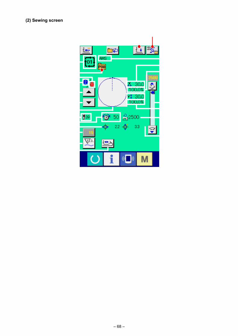
– 68 –
(2) Sewing screen
BCD
E
IK
H
F
J
GL
NM
O
PX
V
W
US
QR
A
T
Y
Button and display Description
A COMBINATION DATA NAME display
Name which is inputted in the combination data being selected is displayed.
B BOBBIN REPLACEMENT button
Bobbin replacement is carried out.→ Refer to "I-4-7. Installing and removing the bobbin case" p.21 .
C PRESSER DOWN button Presser can be lowered and the presser down screen is displayed. To raise the presser, press the presser up button displayed in the presser down screen.
D RETURN TO ORIGIN button
This button returns the presser to the start of sewing and raises the presser when the present presser position is on the way of sewing.
E COMBINATION DATA NO. display
Combination data No. being selected is displayed.
F PATTERN BUTTON NO. display
Pattern button No. being sewn is displayed.
G SEWING SHAPE display Sewing shape which is registered to pattern button No. being sewn is displayed.
H SEWING ORDER RETURN button
Pattern to be sewn can be returned by one.
I SEWING ORDER display Sewing order being sewn at present is displayed.
– 69 –
Button and display Description
J SEWING ORDER ADVANCE button
Pattern to be sewn can be advanced by one.
K TOTAL NUMBER OF REGISTERS display
Total number of patterns which is registered to combination No. being sewn is displayed.
L TOTAL NUMBER OF STITCHES display
Total number of stitches of sewing shape being sewn is displayed.
M THREAD TENSION display
Thread tension value which is registered to pattern button No. being sewn is displayed.
N TRAVEL AMOUNT IN X DIRECTION display
Travel amount in X direction which is registered to the pattern button No. being sewn is displayed.
O COUNTER VALUE CHANGE button
Existing counter value is displayed on this button. When the button is pressed, the counter value change screen is displayed.→ Refer to "II-2-12. Using counter" p.51 .
P COUNTER CHANGEOVER button
The counter display can be changed over among the sewing counter, No. of pcs. counter and bobbin counter.→ Refer to "II-2-12. Using counter" p.51 .
Q X ACTUAL SIZE AMOUNT display
Actual X size value of the sewing shape which is registered to the pattern button No. being sewn is displayed.
R X SCALE RATE display X scale rate of the sewing shape which is registered to the pattern button No. being sewn is displayed.
S SPEED variable resistor Number of revolutions of the sewing machine can be changed.
T Y ACTUAL SIZE AMOUNT display
Actual Y size value of the sewing shape which is registered to the pattern button No. being sewn is displayed.
U Y SCALE RATE display Y scale rate of the sewing shape which is registered to the pattern button No. being sewn is displayed.
V MAX. SPEED LIMITATION display
Maximum speed limitation which is registered to pattern button No. being sewn is displayed.
W TRAVEL AMOUNT IN Y DIRECTION display
Travel amount in Y direction which is registered to the pattern button No. being sewn is displayed.
X STEP SEWING button The step sewing screen is displayed. Checking the pattern shape can be performed.→ Refer to "II-2-7. Checking pattern shape" p.43 .
Y 1-STEP REPEAT button Enable/disable of the 1-step repetition is selected.
: 1-step repeat is disabled
: 1-step repeat is enabled

– 70 –
2-22. Performing combination sewing
(1) Selection of combination data
First, change the sewing mode to the combination sewing before performing setting. → Refer to "II-2-20. Changing sewing mode" p.65 .
① Display the data input screen. Only in case of the data input screen (pink), it is possible to
select the combination data No. In case of the sewing screen (green), press READY switch
to display the data input screen (pink).
② Call the combination data No. screen.
When COMBINATION DATA NO. button A is pressed,
the combination data No. selection screen is displayed. Com-bination data No. which is selected at present and the con-tents are displayed in the upper part of the screen, and other combination data No. buttons which have been registered are displayed in the lower part of the screen.
C
E
F
D
B
③ Select the combination data No.
When UP/DOWN button B is pressed, combination
data No. buttons C which have been registered are changed over in order.
It is also possible to display the combination data No. input
screen using NUMBER INPUT button D and input a
combination data No. directly. Here, press the combination data No. buttons C you desire to
select.
When STEP CONFIRMATION button E is pressed,
the sewing shapes of patterns which have been registered in the combination data and the like are changed over in order and displayed.
④ Determine the combination data No.
When ENTER button F is pressed, the combination
data No. selection screen is closed and the selection is fin-ished.
A

– 71 –
(2) Creating procedure of the combination data
① Display the data input screen. Only in case of the data input screen (pink) it is possible to input
the combination data. In case of the sewing screen (green),
press READY switch to display the data input screen (pink). Pattern No. has not been registered in the initial state, and the
first pattern selection button is displayed in the blank state.
② Display the pattern No. selection screen.
When PATTERN SELECTION button A is pressed, the pattern No. selection screen is displayed.
A
C B
F
ED
I
G
④ Determine the pattern No.
When ENTER button E is pressed, the pattern No. se-
lection screen is closed and the selection is finished.
⑤ Repeat steps ② through ④ as many as the number of pat-tern Nos. you desire to register.
When the first register is determined, the second pattern selec-
tion button F is displayed.
Repeat steps ② through ④ as many as the number of pattern Nos. you desire to register.
When UP or DOWN SCROLL button G is pressed,
the PATTERN NO. button can be selected. The selected PAT-
TERN NO. button is displayed in pink .
When the PATTERN NO. INSERT button H is pressed,
a step is inserted before the pattern No. being selected (dis-played in pink). When PATTERN NO. button I being dis-played is pressed to select a different pattern No., the pattern No. is changed over.
If the programmed combination data extends over two or more screens, the next screen can be displayed by means of
SCREEN SCROLL button J.
H
J
Check to be sure that the selected-mode changeover button K is set to the pattern registration mode. If the mode is not the pattern registration mode, press the selected-mode changeover button K.
③ Select the pattern No.
When UP/DOWN SCROLL button B is pressed,
pattern No. buttons C which have been registered are changed over in order.
It is also possible to display the pattern No. input screen by
means of NUMBER INPUT button D and input a pattern
No. directly. The contents of pattern data are displayed in the buttons. Here, press the pattern No. buttons you desire to select.
K

– 72 –
① Select the combination data No. Perform steps ① to ② of "II-2-22(1) Selection of combina-
tion data" p.70 to make the state that the combination data including the step you desire to delete has been selected.
② Display the pattern No. selection screen.
Press UP/DOWN SCROLL button A to bring the
PATTERN SELECT button for the step to be deleted under the
selected state B. Then, when STEP DELETE button
C is pressed, the data step delete popup window is dis-
played.
③ Performing deleting the step of the selected combination data.
When ENTER button D is pressed, the selected combi-
nation data step is deleted.
When the CANCEL button E is pressed, no data is delet-
ed and the screen is restored to the data input screen.
D
E
A
B
B
C
A
① Select the combination data No. Perform steps ① to ③ of "II-2-22(1) Selection of combina-
tion data" p.70 to display the combination data to be delet-ed.
② Performing deleting the combination data.
When DATA DELETION button A is pressed, the com-
bination data deletion confirmation pop-up is displayed. Here,
press ENTER button B, and the selected combination
data is deleted.
(3) Deleting procedure of the combination data
(4) Deleting procedure of the step of the combination data
– 73 –
2-23. Using the simple operation mode
① Select the sewing mode.
When the key is pressed, SCREEN MODE SELECT
button A is displayed on the screen. When this button is
pressed, the screen mode is changed over between the nor-mal operation and the simple operation.
When the normal operation is selected:
When the simple operation is selected:
A
With IP-420, the SIMPLE OPERATION mode is available.
(5) Setting of the skip of steps
① Entering the skip setting mode
Press mode changeover button A to select skip setting
mode B.A
DE
B
C
② Pressing the button of the step to be skipped. Press button C of the step to display . The step is set to
"Skip". Another press on the button resets the skip setting. It is possible to set two or more steps to "Skip".
When all skip button E or all skip reset button D
is pressed, the skip can be set for all steps or the skip setting can be reset for all steps. Note that the sewing screen is not displayed even by pressing the set ready key when all steps are set to "Skip".
It is possible to set the skipping of sewing of a given step.If you want to skip the sewing of a certain step within the combination data, use this function.
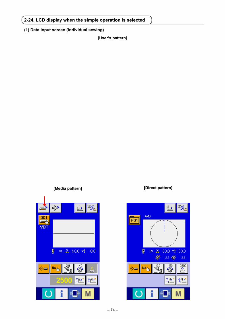
– 74 –
2-24. LCD display when the simple operation is selected
(1) Data input screen (individual sewing)
[User’s pattern]
[Media pattern] [Direct pattern]Ⓐ Ⓑ
ⒷⒶ
F FⒸ
B CL
E
M
F
N
A
DO
H
GI
J
P
K
– 75 –
A EDIT DATA display The data which is being edited on the currently selected edit item is displayed.* When no edit item is selected, this display is not given.
B PRESSER DOWN button This button is used for lowering the cassette clamp and intermediate presser and displaying the work clamp lowering screen.
C BOBBIN REPLACEMENT button
Bobbin replacement is carried out.→ Refer to "I-4-7. Installing and removing the bobbin case" p.21 .
D PATTERN NO. SETTING button
Pattern No. is set. Registered pattern No. is retrieved using PLUS button J and MINUS button K.
E PATTERN TYPE SETTING button
Pattern type is specified. The pattern type is changed over among the following three different ones using PLUS button J and MINUS button K to select a desired one.
: User’s pattern : Vector form data
: M3 data : Standard format of sewing
: Direct pattern
The selected pattern type is indicated on edit data display Q.*A type to which no pattern is registered cannot be selected.
F PATTERN LIST button Pattern No. and type which are currently selected are indicated on the button.When the button is pressed, the selected pattern list screen is displayed for the pattern selection.
G NEEDLE THREAD TENSION SETTING button
The current needle thread tension reference value is indicated on the button. When the button is pressed, the thread tension reference value can be changed. During the setting procedure, the thread tension reference value is indicated on edit data display Q.The thread tension value is increased/decreased in increments of 1 using PLUS button J or MINUS button K.→ Refer to "II-2-6. Changing item data" p.41 .
H MAX SPEED LIMITATION SETTING button
The current max. speed limitation is indicated on the button. When the button is pressed, the max. speed limitation can be changed. During the setting procedure, the max. speed limitation is indicated on edit data display Q.The max. speed limitation is increased/decreased in increments of 100 sti/min using PLUS button J or MINUS button K.→ Refer to "II-2-6. Changing item data" p.41 .
I INTERMEDIATE PRESSER HEIGHT REFERENCE VALUE SETTING button
The current intermediate presser height reference value is indicated on the button. When the button is pressed, the intermediate presser height reference value can be changed. During the setting procedure, the intermediate presser height reference value is indicated on edit data display Q. The intermediate presser height reference value is increased/decreased in increments of 0.1 mm using PLUS button J or MINUS button K.→ Refer to "II-2-6. Changing item data" p.41 .
J PLUS button The value for the selected item is increased in increments of the reference unit.
K MINUS button The value for the selected item is decreased in increments of the reference unit.
L PATTERN NAME display The name of the currently selected pattern is displayed.
M SEWING SHAPE display The sewing shape of the currently selected pattern is displayed
N NUMBER OF STITCHES display
The number of stitches for the currently selected pattern is displayed.
Button and display Description
– 76 –
Button and display DescriptionO X ACTUAL SIZE VALUE
displayThe actual X size value of the sewing shape which is being selected is displayed. When an actual value input is selected, the X ACTUAL VALUE SETTING button is displayed according to the setting of MEMORY switch .→ Refer to "II-2-6. Changing item data" p.41 .
P Y ACTUAL SIZE VALUE display
The actual Y size value of the sewing shape which is being selected is displayed. When an actual value input is selected, the Y ACTUAL VALUE SETTING button is displayed according to the setting of MEMORY switch .→ Refer to "II-2-6. Changing item data" p.41 .
Ⓐ MEDIA PATTERN WRITE button
Data on a media pattern is written. When this button is pressed, the new media pattern registration screen is displayed.* This button is displayed when the media pattern is selected.
Ⓑ USER’S PATTERN WRITE button
Data on a user’s pattern is written. When this button is pressed, the new user’s pattern registration screen is displayed.* This button is displayed when the media pattern is selected.
Ⓒ SEWING DATA TYPE display
The type of data read from a medium is displayed.
: Vector form data
: M3 data
: Standard format of sewing* This display is given when the media pattern is selected.
A TRAVEL AMOUNT IN X DIRECTION display
The amount of travel in the X direction which is registered to the pattern button No. being selected is displayed.* This display is given when a direct pattern is selected.
B TRAVEL AMOUNT IN Y DIRECTION display
The amount of travel in the Y direction which is registered to the pattern button No. being selected is displayed.* This display is given when a direct pattern is selected.
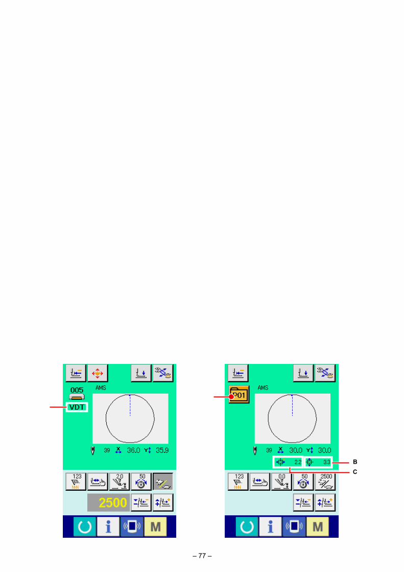
– 77 –
CB
Ⓐ
M A
[User’s pattern]
[Media pattern] [Direct pattern]
(2) Sewing screen (individual sewing)
A BC
P
O
D
M
E
S
F
G
N
Q
J
I
K
R
H
L
– 78 –
A PATTERN BUTTON MOVE button
The pattern button move screen is displayed.→ Refer to "II-2-10. When setting of sewing product is difficult because of interruption of needle tip" p.48 .
B BOBBIN REPLACEMENT button
Bobbin replacement is carried out.→ Refer to "I-4-7. Installing and removing the bobbin case" p.21 .
C PRESSER DOWN button This button is used for lowering the cassette clamp and intermediate presser and displaying the work clamp lowering screen.
D RETURN TO ORIGIN button
The work clamp is returned to the start of sewing and raised to its upper position at the time of a temporary stop.
E SHAPE CHECK button The shape of the pattern which is being selected is checked using PLUS button K or MINUS button L. The current number of stitches is indicated on edit data display S.→ Refer to "II-2-7. Checking pattern shape" p.43 .
F COUNTER VALUE CHANGE button
The counter value is changed using PLUS button K or MINUS button L. The counter value is indicated on the button. When the button is pressed, G is displayed to allow the counter value to be changed.The current counter value is indicated on edit data display S.→ Refer to "II-2-12. Using counter" p.51 .
G CLEAR button The counter value is cleared.* This button is displayed only when COUNTER VALUE CHANGE button F is being selected.
H NEEDLE THREAD TENSION SETTING button
The current needle thread tension reference value is indicated on the button. When the button is pressed, the reference value of the thread tension can be set.During the setting procedure, the thread tension reference value is indicated on edit data display S.The thread tension value is increased/decreased in increments of 1 using PLUS button K or MINUS button L.The thread tension can be changed even during sewing.
I INTERMEDIATE PRESSER HEIGHT REFERENCE VALUE SETTING button
The current intermediate presser height reference value is indicated on the button. When the button is pressed, the intermediate presser height reference value can be set. During the setting procedure, the intermediate presser height reference value is indicated on edit data display S. The intermediate presser height reference value is increased/decreased in increments of 0.1 mm using PLUS button K or MINUS button L.
J SPEED CHANGE button The speed of stitch of the sewing machine is indicated on the button. When the button is pressed, the speed of stitch can be changed. During the setting procedure, the current speed of the sewing machine is indicated on edit data display S.The max. speed limitation is increased/decreased in increments of 100 sti/min using PLUS button K or MINUS button L.
K PLUS button The value for the selected item is increased in increments of the reference unit or the needle is moved forward by one stitch.
L MINUS button The value for the selected item is decreased in increments of the reference unit or the needle is moved backward by one stitch.
M PATTERN NO./TYPE display
The pattern No. and type of the pattern which is being selected are displayed.
N PATTERN NAME display The name of the currently selected pattern is displayed.
Button and display Description
– 79 –
Button and display DescriptionO NUMBER OF STITCHES
displayThe number of stitches for the currently selected pattern is displayed.
P SEWING SHAPE display The sewing shape of the currently selected pattern is displayed.
Q X ACTUAL SIZE VALUE display
The actual X size value of the sewing shape which is being selected is displayed.
R Y ACTUAL SIZE VALUE display
The actual Y size value of the sewing shape which is being selected is displayed.
S EDIT DATA display The data which is being edited on the currently selected edit item is displayed.* When no edit item is selected, this display is not given.
Ⓐ SEWING DATA TYPE display
The type of data read from a medium is displayed.
: Vector form data
: M3 data
: Standard format of sewing* This display is given when the media pattern is selected.
A PATTERN LIST button Pattern No. and type which are currently selected are indicated on the button.When the button is pressed, the selected pattern list screen is displayed for the pattern selection.
B TRAVEL AMOUNT IN X DIRECTION display
The amount of travel in the X direction which is registered to the pattern button No. being selected is displayed.* This display is given when a direct pattern is selected.
C TRAVEL AMOUNT IN Y DIRECTION display
The amount of travel in the Y direction which is registered to the pattern button No. being selected is displayed.* This display is given when a direct pattern is selected.
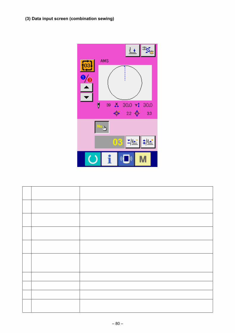
– 80 –
(3) Data input screen (combination sewing)
A PRESSER DOWN button This button is used for lowering the cassette clamp and intermediate presser and displaying the work clamp lowering screen.
B BOBBIN REPLACEMENT button
Bobbin replacement is carried out.→ Refer to "I-4-7. Installing and removing the bobbin case" p.21 .
C SEWING ORDER RETURN button
The pattern No. to be sewn first can be returned to the previous sewing order. The pattern information shown at the upper part of the screen is updated.
D SEWING ORDER ADVANCE button
The pattern No. to be sewn first can be advanced to the next sewing order.The pattern information shown at the upper part of the screen is updated.
E PATTERN No. SETTING button
Pattern No. is set. Registered pattern No. is retrieved using PLUS button G and MINUS button H.
F PATTERN LIST button Pattern No. and type which are currently selected are indicated on the button.When the button is pressed, the selected pattern list screen is displayed for the pattern selection.
G PLUS button The value for the selected item is increased in increments of the reference unit.
H MINUS button The value for the selected item is decreased in increments of the reference unit.
I SEWING ORDER display The sewing order of the currently selected pattern data is displayed.
J TOTAL NUMBER OF REGISTERS display
The total number of patterns registered to the cycle pattern which is currently being selected is displayed.
Button and display Description
A B
F
MN
G
H
K
R
OD
L
E
P Q
IJ
C

– 81 –
K PATTERN NAME display The name of the currently selected pattern is displayed.
L SEWING SHAPE display The sewing shape of the currently selected pattern is displayed.
M NUMBER OF STITCHES display
The number of stitches for the currently selected pattern is displayed.
N X ACTUAL SIZE VALUE display
The actual X size value of the currently selected pattern is displayed.
O Y ACTUAL SIZE VALUE display
The actual Y size value of the currently selected pattern is displayed.
P TRAVEL AMOUNT IN X DIRECTION display
The amount of travel in the X direction of the currently selected pattern is displayed.
Q TRAVEL AMOUNT IN Y DIRECTION display
The amount of travel in the Y direction of the currently selected pattern is displayed.
R EDIT DATA display The data which is being edited on the currently selected edit item is displayed.* When no edit item is selected, this display is not given.
Button and display Description
– 82 –
(4) Sewing screen (combination sewing)
A BOBBIN REPLACEMENT button
Bobbin replacement is carried out.→ Refer to "I-4-7. Installing and removing the bobbin case" p.21 .
B PRESSER DOWN button This button is used for lowering the cassette clamp and intermediate presser and displaying the work clamp lowering screen.
C RETURN TO ORIGIN button
The work clamp is returned to the start of sewing and raised to its upper position at the time of a temporary stop.
D SEWING ORDER RETURN button
The pattern to be sewn can be returned to the previous one.
E SEWING ORDER ADVANCE button
The pattern to be sewn can be advanced to the next one.
F SHAPE CHECK button The shape of the pattern which is being selected is checked using PLUS button J or MINUS button K. The current number of stitches is indicated on edit data display V.→ Refer to "II-2-7. Checking pattern shape" p.43 .
G COUNTER VALUE CHANGE button
The counter value is changed using PLUS button J or MINUS button K. The counter value is indicated on the button. When the button is pressed, H is displayed to allow the counter value to be changed.The current counter value is indicated on edit data display V.→ Refer to "II-2-12. Using counter" p.51 .
Button and display Description
ABC
LO
QSR
T
J
KV
H
I
FU
E
MN
D
G
P
– 83 –
Button and display Description
H CLEAR button The counter value is cleared.* This button is displayed only when COUNTER VALUE CHANGE button G is being selected.
I SPEED CHANGE button The speed of stitch of the sewing machine is changed. The speed of stitch can be changed even during sewing.When this button is pressed, the current speed of stitch of the sewing machine is indicated on edit data display V.The speed of stitch is increased/decreased in increments of 100 sti/min using PLUS button J and MINUS button K.
J PLUS button The value for the selected item is increased in increments of the reference unit or the needle is moved forward by one stitch.
K MINUS button The value for the selected item is decreased in increments of the reference unit or the needle is moved backward by one stitch.
L PATTERN NO./TYPE display
The pattern No. and type of the pattern which is being selected are displayed.
M SEWING ORDER display The sewing order of currently selected pattern data is displayed.
N TOTAL NUMBER OF REGISTERS display
The total number of patterns registered to the cycle pattern which is currently being selected is displayed.
O COMBINATION DATA NAME display
The name input in the combination data which is being selected is displayed.
P SEWING SHAPE display The sewing shape of the currently selected pattern is displayed.
Q NUMBER OF STITCHES display
The number of stitches for the currently selected pattern is displayed.
R X ACTUAL SIZE VALUE display
The actual X size value of the currently selected pattern is displayed.
S Y ACTUAL SIZE VALUE display
The actual Y size value of the currently selected pattern is displayed.
T TRAVEL AMOUNT IN X DIRECTION display
The amount of travel in the X direction of the currently selected pattern is displayed.
U TRAVEL AMOUNT IN Y DIRECTION display
The amount of travel in the Y direction of the currently selected pattern is displayed.
V EDIT DATA display The data which is being edited on the currently selected edit item is displayed.* When no edit item is selected, this display is not given.

– 84 –
No. in pink color such as is put on the data items to
change numerals and the set value can be changed with
D buttons displayed in the change screen.
No. in blue color such as is put on the data items to select pictographs and the pictographs displayed in the change screen can be selected.
→ For the details of memory switch data, refer to "II-3. MEMORY SWITCH DATA LIST" p.94 .
2-25. Changing memory switch data
① Display the memory switch data list screen.
When MODE key is pressed, memory switch button
A is displayed on the screen. When this button is
pressed, the memory switch data list screen is displayed.
② Select the memory switch button you desire to change.
Press UP/DOWN SCROOL button C and select
the data item button B you desire to change.
③ Change the memory switch data. There are data items to change numerals and those to select
pictographs in the memory switch data.
A
B C
D

– 85 –
2-26. Using information
Oil replacement (grease-up) time, needle replacement time, cleaning time, etc. can be specified and the warning notice can be performed after the lapse of the specified time.
(1) Observing the maintenance and inspection information
① Display the information screen.
When information key A of the switch seat section is
pressed in the data input screen, the information screen is displayed.
② Display the maintenance and inspection information screen.
Press maintenance and inspection information screen display
button B in the information screen.
A
B
DE
C
Information on the following three items is displayed in the maintenance and inspection information screen.
• Needle replacement : (1,000 stitches)
• Cleaning time (hour) :
• Oil replacement time (hour) :
The interval to inform of the inspection for each item in button C is displayed at D, and remaining time up to the replace-ment is displayed at E. In addition, remaining time up to the replacement can be cleared.
– 86 –
(2) Releasing procedure of the warning
When the designated inspection time is reached, the warning screen is displayed.
In case of clearing the inspection time, press CLEAR button
A. The inspection time is cleared and the pop-up is closed. In case
of not clearing the inspection time, press CANCEL button B
and close the pop-up. Every time one sewing is completed, the warning screen is displayed until the inspection time is cleared.Warning Nos. of the respective items are as follows. • Needle replacement : A201 • Cleaning time : A202 • Oil replacement time : A203
For the grease-up portion, refer to the item of "III-1-9. Replenishing the designated places with grease" p.121 .
③ Perform clearing remaining time up to the replacement. When button C of the item you desire to clear is pressed, the
time of replacement clear screen is displayed.
When CLEAR button F is pressed, the remaining time
up to the replacement is cleared.
④ Display the threading diagram.
When threading button G displayed in the maintenance
and inspection screen is pressed, the needle thread threading diagram is displayed.
Observe it when performing threading.
F
G
B
A
– 87 –
Data can be sent/received to/from a personal computer or the like, by means of a USB cable.
(3) Performing communication by using USB
If the contact part becomes dirty, failure of contact will be caused. Do not touch by hand, and control so that dust, oil or other foreign material does not adhere to it. In addition, the inside element is damaged by static electrici-ty or the like. So, be very careful when handling.
(2) Performing communication by using the media
For handling way of the media, read "II-1. PREFACE" p.28 .
Communication function can download the sewing data created with other sewing machine, creation of sewing data and sewing data created by editing device PM-1 to the sewing machine. In addition, the function can upload the aforementioned data to the media or personal computer.As the means of communication, a media slot and USB port are prepared. * However, SU-1 (data server utility) is necessary to perform download/upload from the personal
computer.
(1) Handling possible data
Sewing data that can be handled are 4 kinds below, and the respective data formats are as shown be-low.
xxx: file No.
* For the simplified program, see the Engineer's Manual.
2-27. Using communication function
Data name Extension Description of data
Vector format data VD00XXX.VDTIt is the data of needle entry point created with PM-1, and the data format that can be operated in common between JUKI sewing machines.
M3 data AMS0XXX.M3 Pattern data for the AMS-B, -C and -D Series
Sewing standard format data
SD00XXX.DAT Data of sewing standard format
Simplified program data AMS0XXX.PRO Simplified program data

– 88 –
④ Determine the data No.
When ENTER button G is pressed, the data No. se-
lection screen is closed and the selection of the data No. has been completed.
⑤ Start communication.
When COMMUNICATION START button H is pressed,
the data communication starts. The during communication screen is displayed during communication and the screen returns to the communication screen after the end of commu-nication.
Do not open the cover during reading the data. Data may not be read in.
① Display the communication screen.
When communication switch A of switch seat section is
pressed in the data input screen, the communication screen is displayed.
② Select the communication procedure. There are four communication procedures as described below. B Writing data from media to panel C Writing data from personal computer (server) to panel D Writing data from panel to media E Writing data from panel to personal computer (server) Select the button of communication procedure you desire.
③ Select the data No.
When F is pressed, the writing file selection screen is
displayed. Input the file No. of the data you desire to write. For the file
No., input the numerals of the part xxx of VD00xxx .vdt of the file name.
Designation of the pattern No. of writing destination can be performed in the same way. When the writing destination is the panel, pattern Nos. which have not been registered are displayed.
(4) Take-in of the data
B
D
C
F
A
E
G
H

– 89 –
(5) Taking in plural data together
It is possible for vector data, M3 data and sewing standard format data to select plural writing data and write them together. Pattern No. of writing destination will become the same No. of the selected data No.
① Display the writing file selection screen.
When PLURAL SELECTION button A is pressed, the
data No. plural selection screen is displayed.
② Perform the data No. selection. Since the list of existing data file numbers is displayed, press
FILE NO. button B you desire to write. It is possible to invert
the selected state of the button with INVERSION button
C.
③ Determine the data No.
When ENTER button D is pressed, the data No. plural
selection screen is closed and the data selection ends.
④ Start the communication.
When COMMUNICATION START button E is pressed,
the data communication starts.
A
C
B
D
E

– 90 –
Data No. during communication, total number of writing data and number of data that have ended the data communication are dis-played in the during communication screen.
* When performing writing to the pattern No. which already exists, the overwriting confirmation screen is displayed before writing. When performing overwriting, press ENTER button
F.
When performing overwriting all without displaying the over-writing confirmation screen, press OVERWRITING button
G in all cases.
F
G

– 91 –
① Display the media format screen.
When switch is held pressed for three seconds, MEDIA
FORMAT button A is displayed on the screen. When
this button is pressed, the media format screen is displayed.
2-28. Performing formatting of the media
To re-format a medium, the IP-420 has to be used. The IP-420 is not able to read any medium which is formatted on a personal computer.
② Start formatting of the media. Set the media you desire to format to the media slot, close
the cover, press ENTER button B and formatting starts.
Save necessary data in the media to the other media before formatting. When formatting is performed, the inside data are deleted.
BWhen two or more media are connected to the sewing machine, the medium to be formatted is determined by the predetermined priority order. High ← LowCF(TM) slot ← USB device 1 ← USB device 2 ← ....When a CompactFlash (TM) is inserted in the CF(TM) slot, the CompactFlash (TM) will be formatted accord-ing to the priority order as shown above.Refer to the USB specifications for the priority order of access.
A
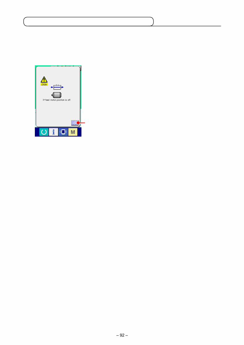
– 92 –
A
2-29. Operation at the time of X/Y motor position slip
When X/Y motor detects the position slip, the error screen is displayed.Timing of error display can be changed with the selection of memory switch. For the details, refer to the Engineer's Manual.
(1) When the error is displayed during sewing
① Release the error.
Press RESET button A to release the error and the
thread trimming pop-up is displayed.
② Perform thread trimming. Check the finished seam. If the seam has no problem, press
the start switch to re-start sewing in the as is state.
If not, press THREAD TRIM button B and perform
thread trimming. When performing thread trimming, the feed forward/back pop-
up is displayed.
③ Adjust the presser to the re-sewing position.
Every time FEED BACK button C is pressed, the press-
er returns by one stitch. Every time FEED FORWARD button
D is pressed, the presser moves forward by one stitch.
Move the presser up to the re-sewing position.
In addition, when RETURN TO ORIGIN button E is
pressed, the pop-up is closed, the sewing screen is displayed, and the presser returns to the sewing start position.
④ Re-start sewing. When the start switch is pressed, the sewing machine re-starts
sewing.
B
EDC

– 93 –
A
(2) When the error is displayed after end of sewing
① Release the error.
When RESET button A is pressed, and the error is re-
leased, the sewing screen is displayed.
② Perform sewing work again from the start. When the start switch is pressed, the sewing machine starts
sewing.
(3) When the rest switch is not displayed When a large slip is detected, the reset switch is not displayed.
① Turn OFF the power.
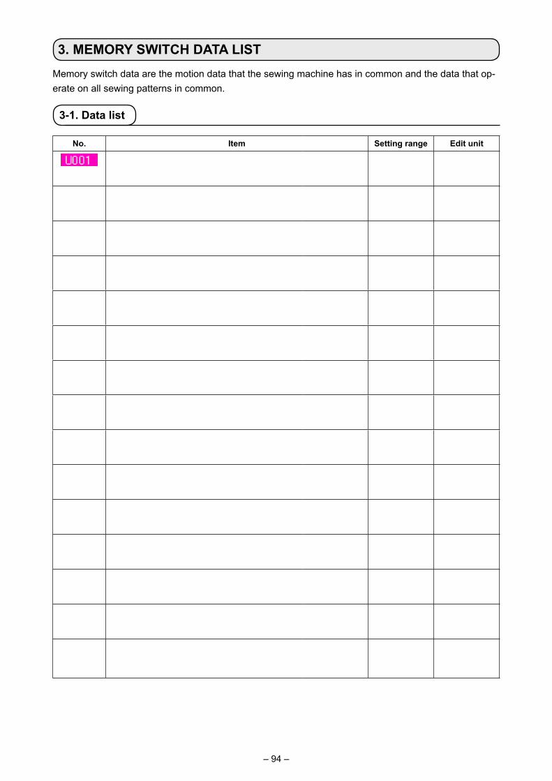
– 94 –
3. MEMORY SWITCH DATA LISTMemory switch data are the motion data that the sewing machine has in common and the data that op-erate on all sewing patterns in common.
3-1. Data list
No. Item Setting range Edit unit
Maximum sewing speed 200 to 2500 100 sti/min
Sewing speed of 1st stitch 200 to 1500 100 sti/min
Sewing speed of 2nd stitch 200 to 2500 100 sti/min
Sewing speed of 3rd stitch 200 to 2500 100 sti/min
Sewing speed of 4th stitch 200 to 2500 100 sti/min
Sewing speed of 5th stitch 200 to 2500 100 sti/min
Thread tension setting at the time of thread trimming
0 to 200 1
Thread tension changeover timing at the time of thread trimming
– 6 to 4 1
Sewing speed of 1st stitch Acceleration/deceleration at the corner section
200 to 900 100 sti/min
Sewing speed of 2nd stitchAcceleration/deceleration at the corner section
200 to 2500 100 sti/min
Sewing speed of 3rd stitchAcceleration/deceleration at the corner section
200 to 2500 100 sti/min
Sewing speed of 4th stitchAcceleration/deceleration at the corner section
200 to 2500 100 sti/min
Sewing speed of 5th stitchAcceleration/deceleration at the corner section
200 to 2500 100 sti/min
Thread tension of 1st stitch 0 to 200 1
Thread tension changeover timing at the time of sewing start
– 5 to 2 1
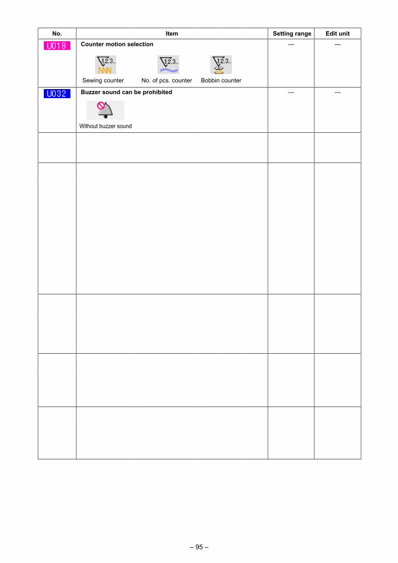
– 95 –
No. Item Setting range Edit unit
Counter motion selection --- ---
Sewing counter No. of pcs. counter Bobbin counter
Buzzer sound can be prohibited --- ---
Without buzzer sound
Panel operating sound Panel operating sound + error
Feed motion timing is selectedSet the timing in “–” direction when stitch is not well-tightened.
- 8 to 16 1
This memory switch is used for selecting the releasing method of the cassette clamp after the completion of sewing
--- ---
Cassette clamp is released after the clamp has returned to
the sewing start position.
Cassette clamp is released first and it returns to the
sewing start position.
Cassette clamp is released with the eject switch after it has returned to the sewing
start position.
Cassette clamp is released with the eject switch after it has returned to
the sewing start position.The sewing machine starts sewing
with the start switch.
This memory switch is used for setting the release of cassette clamp at the end of sewing
--- ---
Normal Release of the cassette clamp is prohibited.
Origin retrieval can be performed every time after end of sewing (other than combination sewing)
--- ---
Without origin retrieval With origin retrieval
Origin retrieval in combination sewing can be set --- ---
Without origin retrieval
Every time 1 pattern is finished.
Every time 1 cycle is finished.
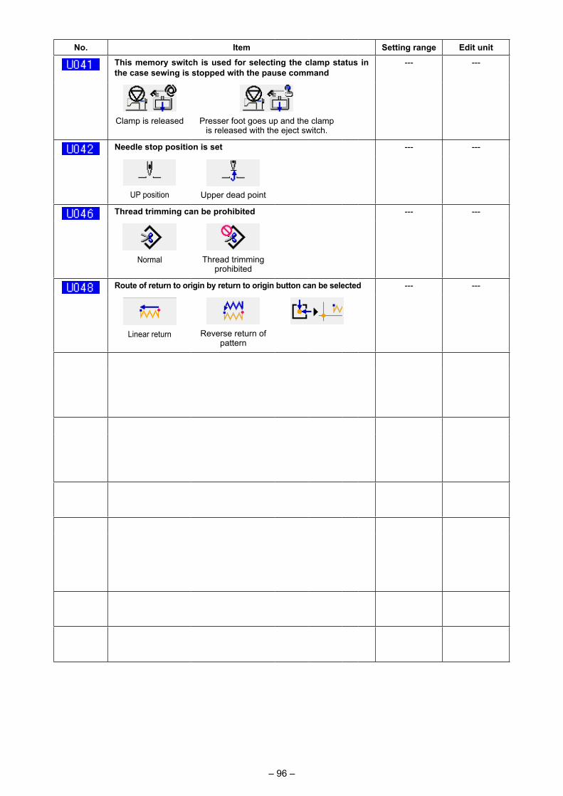
– 96 –
No. Item Setting range Edit unit
This memory switch is used for selecting the clamp status in the case sewing is stopped with the pause command
--- ---
Clamp is released Presser foot goes up and the clamp is released with the eject switch.
Needle stop position is set --- ---
UP position Upper dead point
Thread trimming can be prohibited --- ---
Normal Thread trimming prohibited
Route of return to origin by return to origin button can be selected --- ---
Linear return Reverse return of pattern
Origin retrieval → Sewing start point
Motion method of wiper can be selected --- ---
Invalid Magnet typewiper
Unit of sewing shape size change can be selected --- ---
%input Actual size input
Thread tension output time when setting thread tension can be set
0 to 20 1 S
Thread breakage detection selection --- ---
Thread breakage detection invalid
Thread breakage detection valid
Number of invalid stitches at the start of sewing of thread breakage detection
0 to 15 stitches
1 stitch
Number of invalid stitches during sewing of thread breakage detection
0 to 15 stitches
1 stitch
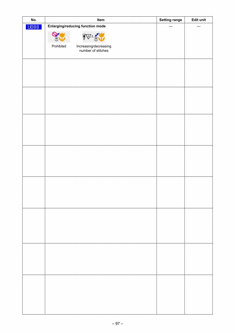
– 97 –
No. Item Setting range Edit unit
Enlarging/reducing function mode --- ---
Prohibited Increasing/decreasing number of stitches
(Pitch is fixed.)
Increasing/decreasing pitch (Number of stitches is fixed.)
Jog move function mode --- ---
Prohibited Parallel move 2nd origin specified later
Retainer compensation motion : selection of motion --- ---
Without motion With motion
Selection of needle upper dead point at the time of origin retrieval/return to origin
--- ---
Without With
Temporary stop : thread trimming operation --- ---
Automatic thread trimming
Manual (Thread trimming by turning Stop SW ON again)
Main motor X/Y feed synchronized control : speed/pitch --- ---
2500 sti/min/ 3.0 mm
2200 sti/min/ 3.0 mm
1800 sti/min/ 3.0 mm
1400 sti/min/ 3.0 mm
Intermediate presser with/without control --- ---
Without (Lowering fixed)
With (Lowering with sewing data at the time of operation)
With (Lowering even at the time of feed forward/backward)
Intermediate presser lowering timing --- ---
Immediately before start-up of machine head
Synchronized with the cassette clamp
Intermediate presser : wiper sweeping position --- ---
Sweeping above intermediate
presser
Sweeping above inter-mediate presser (posi-tion where intermediate
presser lowers most)
Sweeping below intermediate
presser
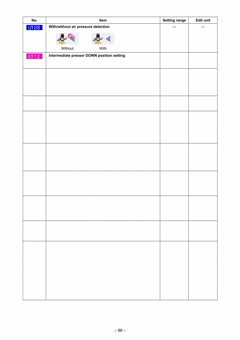
– 98 –
No. Item Setting range Edit unit
With/without air pressure detection --- ---
Without With
Intermediate presser DOWN position setting→ Refer to "I-4-11. Intermediate presser height" p.26 .
0 to 7.0 mm 0.1 mm
With/without needle cooler control --- ---
Without With
The time to automatically exit from the count-up screen can be set
0 to 99 1
Selection of needle upper dead point at the time of origin retrieval/return to origin
--- ---
Without With
This memory switch is used for selecting the direction. --- ---
Perfect stitch Hitch stitch No turning
This memory switch is used for offsetting the angelAngle offset value of the turning shaft on the arm side with respect to the turning shaft on the bed side is set.
-180 to 180 1°
Grease-up errorClearing of number of stitches of grease-up is performed.→ Refer to "III-1-9. Replenishing the designated places with grease" p.121 .
--- ---
Number of revolutions of the slip ringThe number of revolutions of the slip ring is cleared.→ Refer to the Engineer's Manual.
--- ---
Language selection --- ---
Japanese English Chinese (traditional)
Chinese (simplified)
Spanish Italian French German
Portuguese Turkish Vietnamese Korean
Indonesian Russian
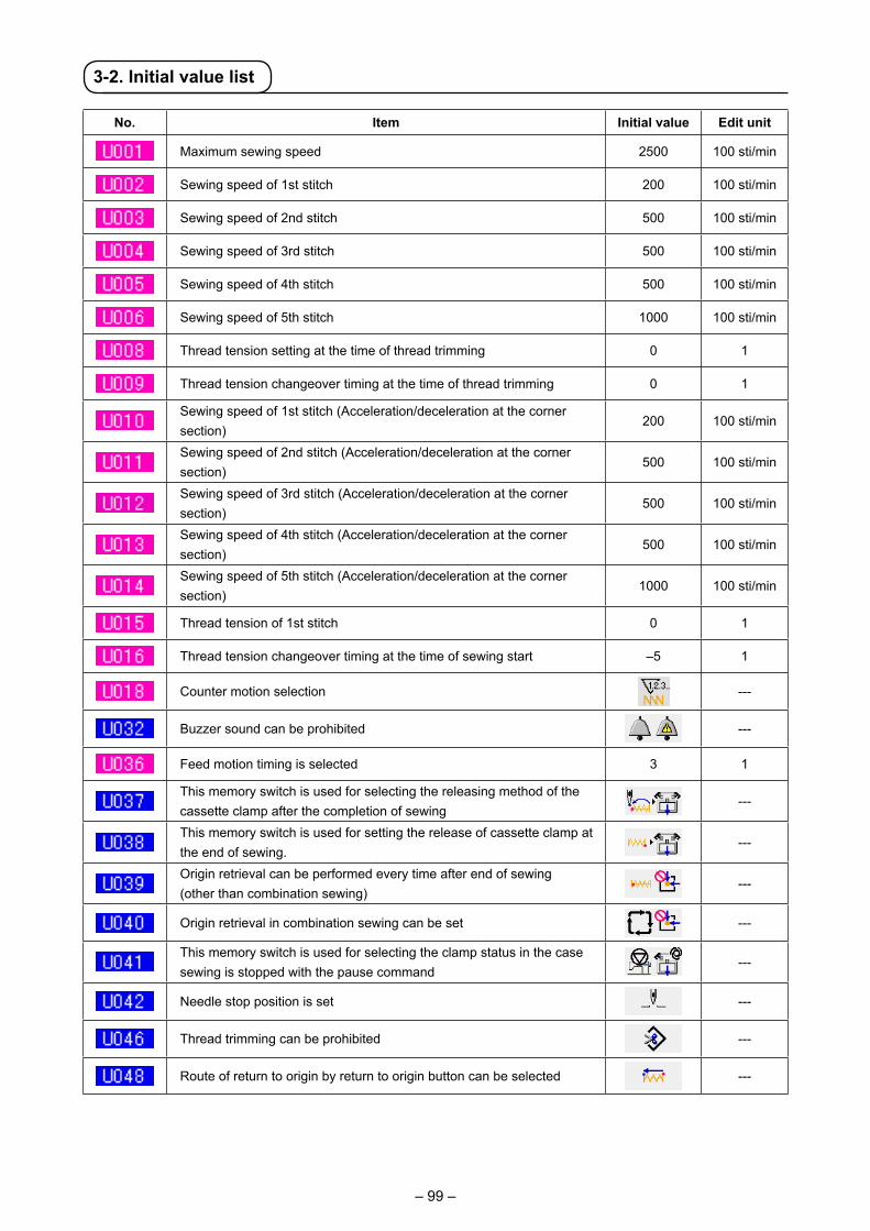
– 99 –
3-2. Initial value list
No. Item Initial value Edit unit
Maximum sewing speed 2500 100 sti/min
Sewing speed of 1st stitch 200 100 sti/min
Sewing speed of 2nd stitch 500 100 sti/min
Sewing speed of 3rd stitch 500 100 sti/min
Sewing speed of 4th stitch 500 100 sti/min
Sewing speed of 5th stitch 1000 100 sti/min
Thread tension setting at the time of thread trimming 0 1
Thread tension changeover timing at the time of thread trimming 0 1
Sewing speed of 1st stitch (Acceleration/deceleration at the corner section)
200 100 sti/min
Sewing speed of 2nd stitch (Acceleration/deceleration at the corner section)
500 100 sti/min
Sewing speed of 3rd stitch (Acceleration/deceleration at the corner section)
500 100 sti/min
Sewing speed of 4th stitch (Acceleration/deceleration at the corner section)
500 100 sti/min
Sewing speed of 5th stitch (Acceleration/deceleration at the corner section)
1000 100 sti/min
Thread tension of 1st stitch 0 1
Thread tension changeover timing at the time of sewing start –5 1
Counter motion selection ---
Buzzer sound can be prohibited ---
Feed motion timing is selected 3 1
This memory switch is used for selecting the releasing method of the cassette clamp after the completion of sewing
---
This memory switch is used for setting the release of cassette clamp at the end of sewing.
---
Origin retrieval can be performed every time after end of sewing (other than combination sewing)
---
Origin retrieval in combination sewing can be set ---
This memory switch is used for selecting the clamp status in the case sewing is stopped with the pause command
---
Needle stop position is set ---
Thread trimming can be prohibited ---
Route of return to origin by return to origin button can be selected ---
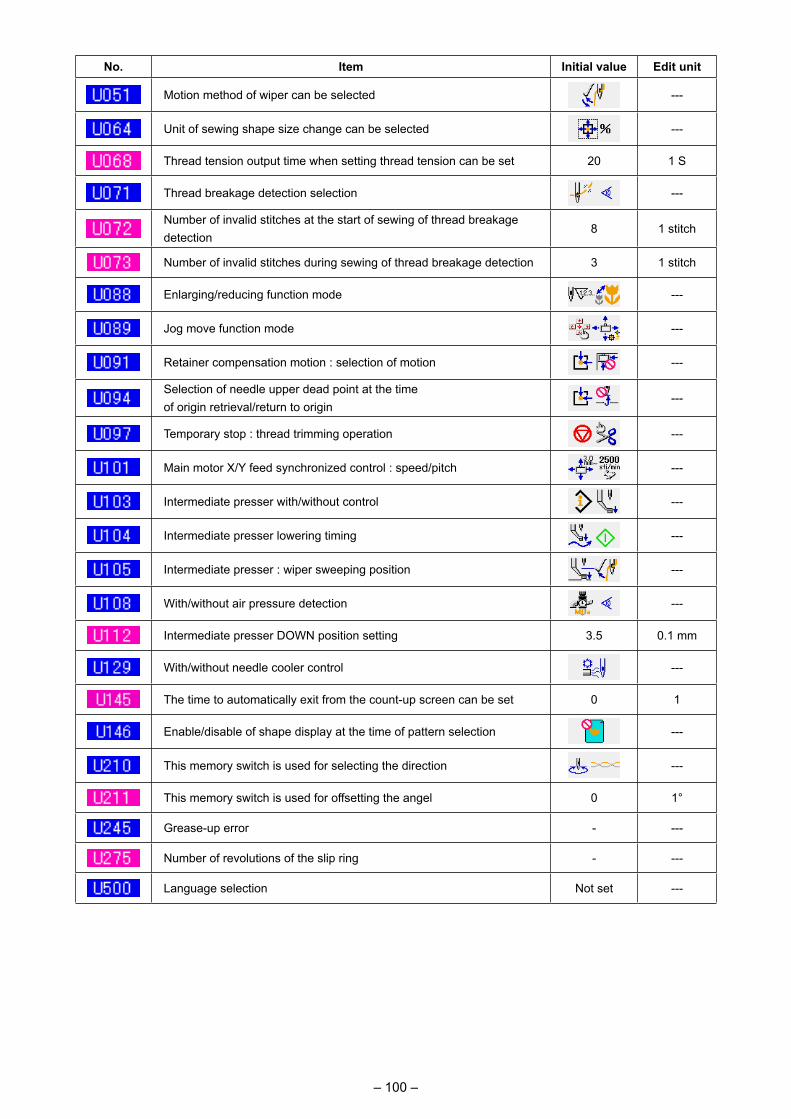
– 100 –
No. Item Initial value Edit unit
Motion method of wiper can be selected ---
Unit of sewing shape size change can be selected ---
Thread tension output time when setting thread tension can be set 20 1 S
Thread breakage detection selection ---
Number of invalid stitches at the start of sewing of thread breakage detection
8 1 stitch
Number of invalid stitches during sewing of thread breakage detection 3 1 stitch
Enlarging/reducing function mode ---
Jog move function mode ---
Retainer compensation motion : selection of motion ---
Selection of needle upper dead point at the time of origin retrieval/return to origin
---
Temporary stop : thread trimming operation ---
Main motor X/Y feed synchronized control : speed/pitch ---
Intermediate presser with/without control ---
Intermediate presser lowering timing ---
Intermediate presser : wiper sweeping position ---
With/without air pressure detection ---
Intermediate presser DOWN position setting 3.5 0.1 mm
With/without needle cooler control ---
The time to automatically exit from the count-up screen can be set 0 1
Enable/disable of shape display at the time of pattern selection ---
This memory switch is used for selecting the direction ---
This memory switch is used for offsetting the angel 0 1°
Grease-up error - ---
Number of revolutions of the slip ring - ---
Language selection Not set ---
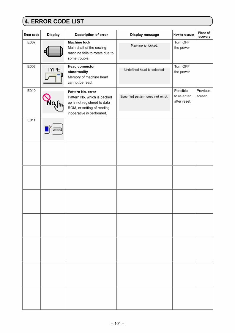
– 101 –
4. ERROR CODE LIST
Error code Display Description of error Display message How to recover Place of recovery
E007 Machine lockMain shaft of the sewing machine fails to rotate due to some trouble.
Turn OFF the power
E008 Head connector abnormalityMemory of machine head cannot be read.
Turn OFF the power
E010 Pattern No. errorPattern No. which is backed up is not registered to data ROM, or setting of reading inoperative is performed.
Possible to re-enter after reset.
Previous screen
E011 External media not insertedExternal media is not inserted.
Possible to re-enter after reset.
Previous screen
E012 Read errorData read from external media cannot be performed.
Possible to re-start after reset.
Previous screen
E013 Write errorData write from external media cannot be performed.
Possible to re-start after reset.
Previous screen
E015 Format errorFormat cannot be performed.
Possible to re-start after reset.
Previous screen
E016 External media capacity overCapacity of external media is short.
Possible to re-start after reset.
Previous screen
E017 Machine memory capacity overMachine memory capacity is insufficient.
Possible to re-start after reset.
Previous screen
E019 File size overFile is too large.
Possible to re-start after reset.
Previous screen
E024 Pattern data size overMemory size is over.
Possible to re-start after reset.
Data input screen
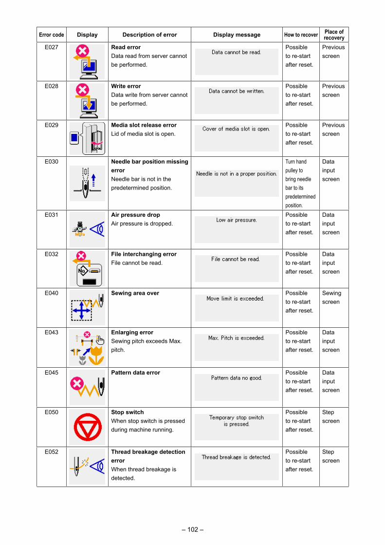
– 102 –
Error code Display Description of error Display message How to recover Place of recovery
E027 Read errorData read from server cannot be performed.
Possible to re-start after reset.
Previous screen
E028 Write errorData write from server cannot be performed.
Possible to re-start after reset.
Previous screen
E029 Media slot release errorLid of media slot is open.
Possible to re-start after reset.
Previous screen
E030 Needle bar position missing errorNeedle bar is not in the predetermined position.
Turn hand pulley to bring needle bar to its predetermined position.
Data inputscreen
E031 Air pressure dropAir pressure is dropped.
Possible to re-start after reset.
Data inputscreen
E032 File interchanging errorFile cannot be read.
Possible to re-start after reset.
Data inputscreen
E040 Sewing area over Possible to re-start after reset.
Sewing screen
E043 Enlarging errorSewing pitch exceeds Max. pitch.
Possible to re-start after reset.
Data inputscreen
E045 Pattern data error Possible to re-start after reset.
Data input screen
E050 Stop switchWhen stop switch is pressed during machine running.
Possible to re-start after reset.
Step screen
E052 Thread breakage detection errorWhen thread breakage is detected.
Possible to re-start after reset.
Step screen
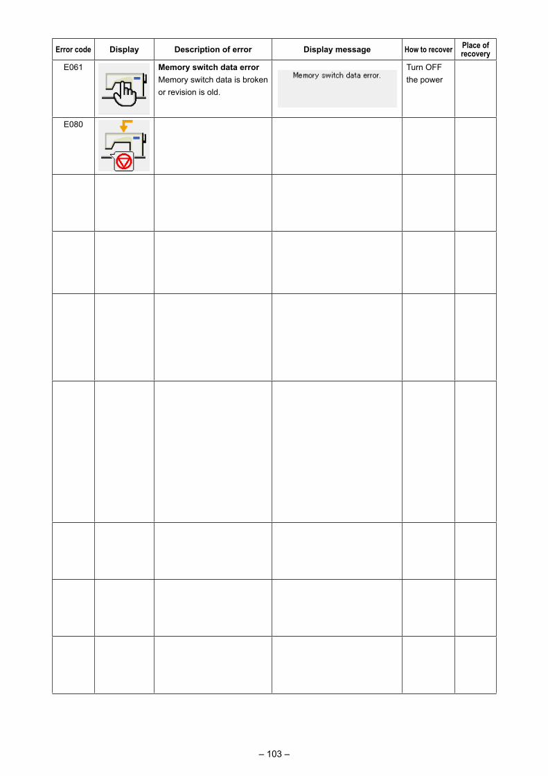
– 103 –
Error code Display Description of error Display message How to recover Place of recovery
E061 Memory switch data errorMemory switch data is broken or revision is old.
Turn OFF the power
E080 External stop switch Possible to re-start after reset.
Step screen
E101 Safety cover sensor error Close the safety cover.
Previous screen
E204 USB connection errorWith the number of times of sewing has reached 10 or more, with a USB device con-nected to the sewing machine
Possible to re-start after reset.
Sewing screen
E220 Grease-up warningAt the time of operation of 100 million stitches→ Refer to "III-1-9.
Replenishing the designated places with grease" p.121 .
Possible to re-start after reset.
Data input screen
E221 Grease-up errorAt the time of operation of 120 million stitchesThe sewing machine is put in the sewing-impossible status. It is possible to clear with
memory switch .
→ Refer to "III-1-9. Replenishing the designated places with grease" p.121 .
Possible to re-start after reset.
Data input screen
E298 Warning against maintenance of slip ring
Possible to re-start after reset.
Data input screen
E299 Slip ring maintenance error Possible to re-start after reset.
Data input screen
E303 Meniscal sensor error Turn OFF the power
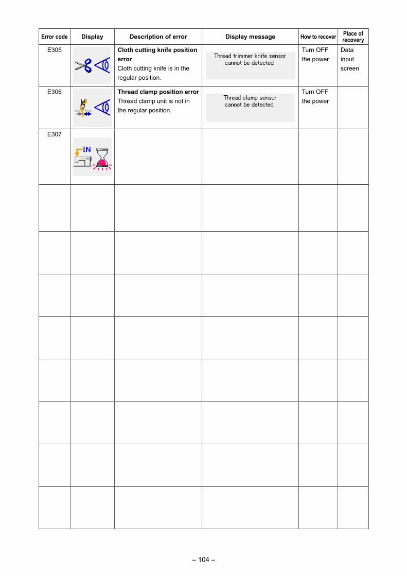
– 104 –
Error code Display Description of error Display message How to recover Place of recovery
E305 Cloth cutting knife position errorCloth cutting knife is in the regular position.
Turn OFF the power
Data input screen
E306 Thread clamp position errorThread clamp unit is not in the regular position.
Turn OFF the power
E307 External input command time out errorInput is not performed for a fixed period of time with the external input command of vector data.
Possible to re-start after reset.
Data inputscreen
E308 Time-out error of wait terminalThere is no input to wait terminal for a certain period of time.
Turn OFF the power
E310 Hook cover sensor error Close the hook cover.
Previous screen
E311 Hook motor origin sensor error
Turn OFF the power
E312 Machine-head turning motor origin sensor error
Turn OFF the power
E313 Hook turning motor origin sensor error
Turn OFF the power
E374 Intermediate presser down sensor error
Turn OFF the power
E375 Bobbin replacement door-close sensor error
Turn OFF the power
E376 Bobbin replacement door-open sensor error
Turn OFF the power
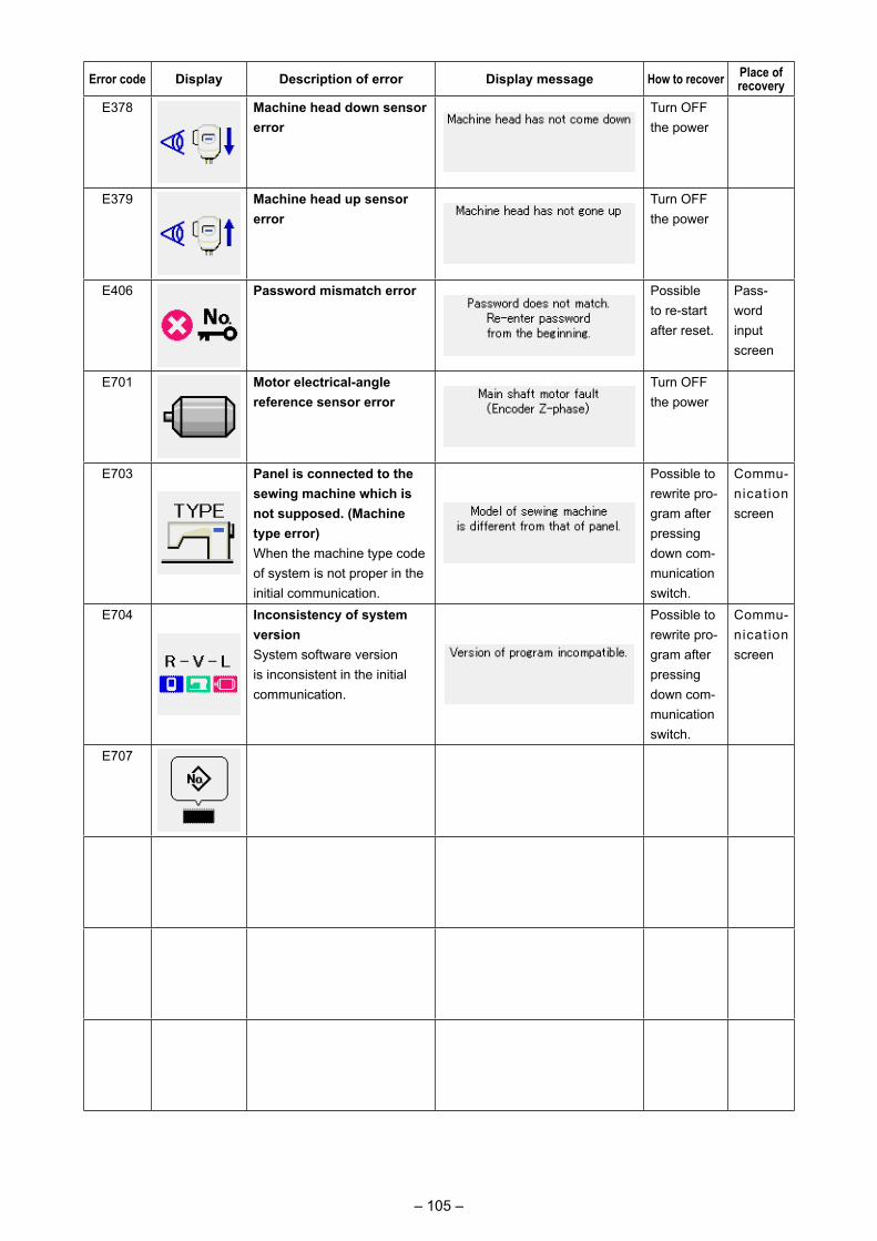
– 105 –
Error code Display Description of error Display message How to recover Place of recovery
E378 Machine head down sensor error
Turn OFF the power
E379 Machine head up sensor error
Turn OFF the power
E406 Password mismatch error Possible to re-start after reset.
Pass-word input screen
E701 Motor electrical-angle reference sensor error
Turn OFF the power
E703 Panel is connected to the sewing machine which is not supposed. (Machine type error)When the machine type code of system is not proper in the initial communication.
Possible to rewrite pro-gram after pressing down com-munication switch.
Commu-nicat ion screen
E704 Inconsistency of system versionSystem software version is inconsistent in the initial communication.
Possible to rewrite pro-gram after pressing down com-munication switch.
Commu-nicat ion screen
E707 NAND flash ROM is not formatted
Turn OFF the power
E708 NAND flash ROM is inaccessible
Possible to re-start after reset.
Previous screen
E721 Hook motor encoder failure Turn OFF the power
E722 Hook motor hall sensor failure
Turn OFF the power
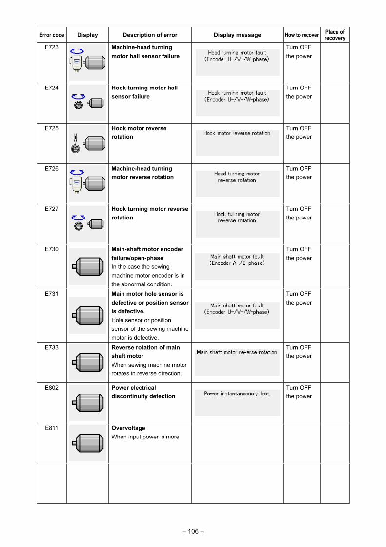
– 106 –
Error code Display Description of error Display message How to recover Place of recovery
E723 Machine-head turning motor hall sensor failure
Turn OFF the power
E724 Hook turning motor hall sensor failure
Turn OFF the power
E725 Hook motor reverse rotation
Turn OFF the power
E726 Machine-head turning motor reverse rotation
Turn OFF the power
E727 Hook turning motor reverse rotation
Turn OFF the power
E730 Main-shaft motor encoder failure/open-phaseIn the case the sewing machine motor encoder is in the abnormal condition.
Turn OFF the power
E731 Main motor hole sensor is defective or position sensor is defective.Hole sensor or position sensor of the sewing machine motor is defective.
Turn OFF the power
E733 Reverse rotation of main shaft motorWhen sewing machine motor rotates in reverse direction.
Turn OFF the power
E802 Power electrical discontinuity detection
Turn OFF the power
E811 OvervoltageWhen input power is more than the specified value.
Turn OFF the power
E813 Low voltageWhen input power is less than the specified value.
Turn OFF the power
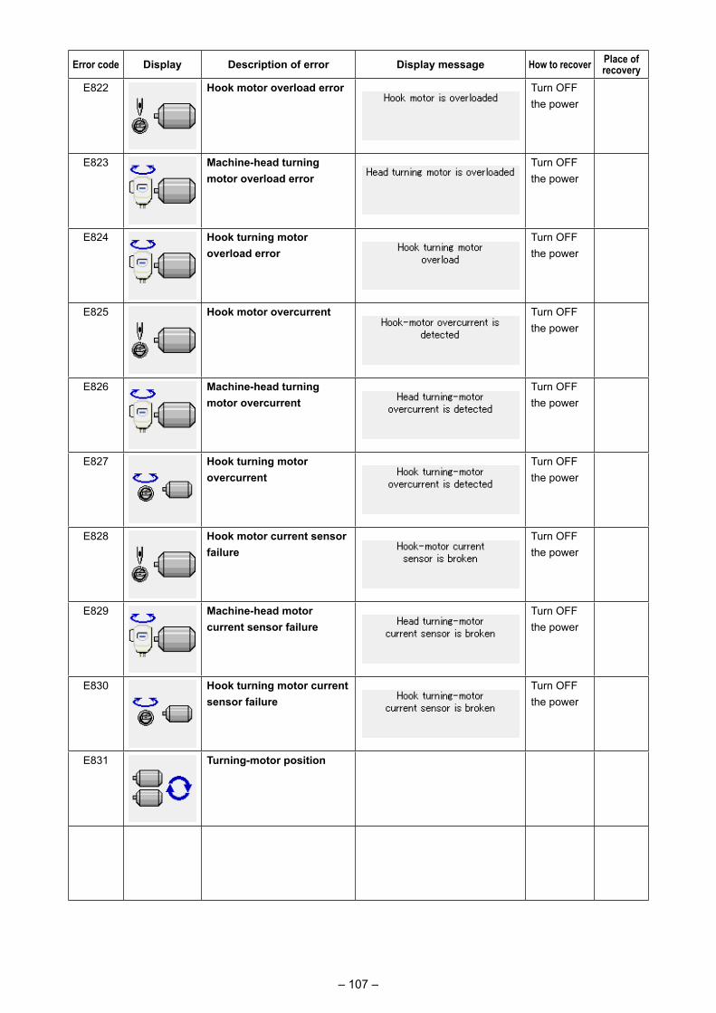
– 107 –
Error code Display Description of error Display message How to recover Place of recovery
E822 Hook motor overload error Turn OFF the power
E823 Machine-head turning motor overload error
Turn OFF the power
E824 Hook turning motor overload error
Turn OFF the power
E825 Hook motor overcurrent Turn OFF the power
E826 Machine-head turning motor overcurrent
Turn OFF the power
E827 Hook turning motor overcurrent
Turn OFF the power
E828 Hook motor current sensor failure
Turn OFF the power
E829 Machine-head motor current sensor failure
Turn OFF the power
E830 Hook turning motor current sensor failure
Turn OFF the power
E831 Turning-motor position excessive-deviation error
Turn OFF the power
E832 Main shaft/hook synchronization error
Turn OFF the power
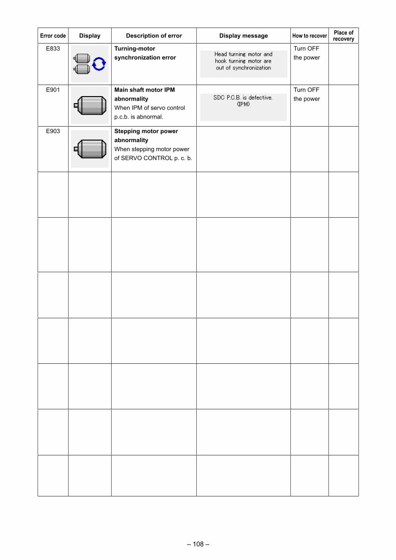
– 108 –
Error code Display Description of error Display message How to recover Place of recovery
E833 Turning-motor synchronization error
Turn OFF the power
E901 Main shaft motor IPM abnormalityWhen IPM of servo control p.c.b. is abnormal.
Turn OFF the power
E903 Stepping motor power abnormalityWhen stepping motor power of SERVO CONTROL p. c. b. fluctuates more than ± 15%.
Turn OFF the power
E904 Solenoid power abnormalityWhen solenoid power of SERVO CONTROL p. c. b.fluctuates more than ± 15%.
Turn OFF the power
E905 Heat sink temperature for SERVO CONTROL p. c. b. abnormalityTurn ON the power again after taking overheat time of SERVO CONTROL p. c. b.
Turn OFF the power
E907 X feed motor origin retrieval errorWhen origin sensor signal is not inputted at the time of origin retrieval motion.
Turn OFF the power
E908 Y feed motor origin retrieval errorWhen origin sensor signal is not inputted at the time of origin retrieval motion.
Turn OFF the power
E910 Presser motor origin retrieval errorWhen origin sensor signal is not inputted at the time of origin retrieval motion.
Turn OFF the power
E913 Thread clamp origin retrieval errorWhen origin sensor signal is not inputted at the time of origin retrieval motion.
Turn OFF the power
E914 Feed defective errorTiming lag between feed and main shaft occurs.
Turn OFF the power
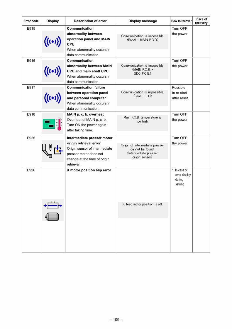
– 109 –
Error code Display Description of error Display message How to recover Place of recovery
E915 Communication abnormality between operation panel and MAIN CPUWhen abnormality occurs in data communication.
Turn OFF the power
E916 Communication abnormality between MAIN CPU and main shaft CPUWhen abnormality occurs in data communication.
Turn OFF the power
E917 Communication failure between operation panel and personal computerWhen abnormality occurs in data communication.
Possible to re-start after reset.
E918 MAIN p. c. b. overheat Overheat of MAIN p. c. b.Turn ON the power again after taking time.
Turn OFF the power
E925 Intermediate presser motor origin retrieval errorOrigin sensor of intermediate presser motor does not change at the time of origin retrieval.
Turn OFF the power
E926 X motor position slip error 1. In case of error display during sewing
Possible to re-start after reset
2. In case of error display after end of sewing
Possible to re-start after reset
3. In case of others
Turn OFF the power.
1. Step screen
2. Sewing screen
3. -------
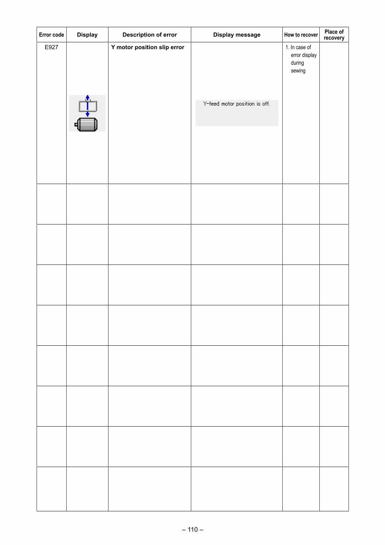
– 110 –
Error code Display Description of error Display message How to recover Place of recovery
E927 Y motor position slip error 1. In case of error display during sewing
Possible to re-start after reset
2. In case of error display after end of sewing
Possible to re-start after reset
3. In case of others
Turn OFF the power.
1. Step screen
2. Sewing screen
3. -------
E928 Thread trimming motor position slip error
Turn OFF the power
E930 Intermediate presser motor position slip error
Turn OFF the power
E931 X motor overload error Turn OFF the power
E932 Y motor overload error Turn OFF the power
E933 Thread trimming motor overload error
Turn OFF the power
E935 Intermediate presser motor overload error
Turn OFF the power
E936 X/Y motor out of range error
Turn OFF the power
E943 MAIN CONTROL p.c.b troubleWhen data writing to MAIN CONTROL p.c.b. cannot be performed.
Turn OFF the power
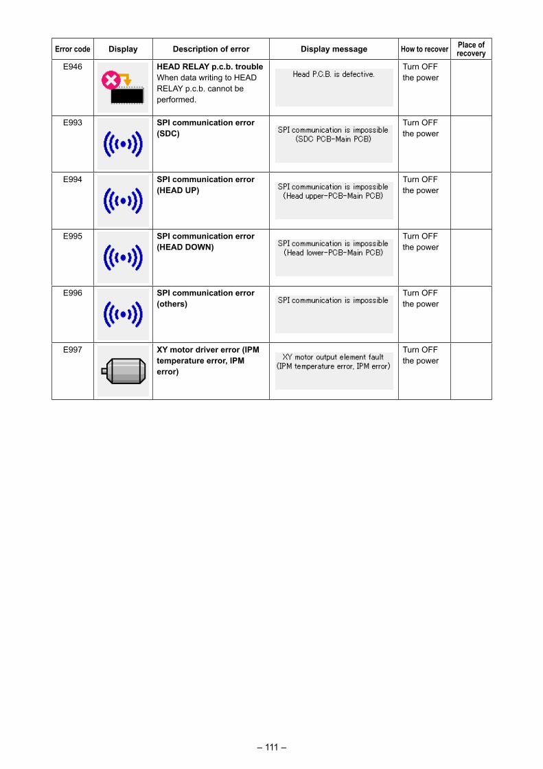
– 111 –
Error code Display Description of error Display message How to recover Place of recovery
E946 HEAD RELAY p.c.b. troubleWhen data writing to HEAD RELAY p.c.b. cannot be performed.
Turn OFF the power
E993 SPI communication error (SDC)
Turn OFF the power
E994 SPI communication error (HEAD UP)
Turn OFF the power
E995 SPI communication error (HEAD DOWN)
Turn OFF the power
E996 SPI communication error (others)
Turn OFF the power
E997 XY motor driver error (IPM temperature error, IPM error)
Turn OFF the power
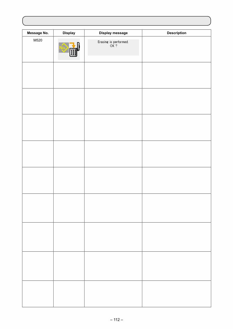
– 112 –
Message No. Display Display message Description
M520 Erase confirmation of Users' pattern Erase is performed. OK ?
M521 Erase confirmation of pattern button Erase is performed. OK ?
M522 Erase confirmation cycle patternErase is performed. OK ?
M523 Erase confirmation of backup data Pattern data is not stored in memory. Erase is OK ?
M528 Overwriting confirmation of users' pattern Overwriting is performed. OK ?
M529 Overwriting confirmation of mediaOverwriting is performed. OK ?
M530 Overwriting confirmation of vector data of panel/M3 data/sewing standard format data/simplified program data Overwriting is performed. OK ?
M531 Overwriting confirmation of vector data of media/M3 data/sewing standard format data/simplified program dataOverwriting is performed. OK ?
M532 Overwriting confirmation of vector data on personal computer/M3 data/sewing standard format data/simplified program dataOverwriting is performed. OK ?
M534 Overwriting confirmation of adjustment data of media and all machine dataOverwriting is performed. OK ?
5. MESSAGE LIST
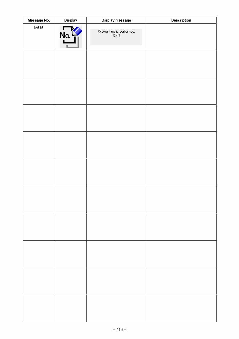
– 113 –
Message No. Display Display message Description
M535 Overwriting confirmation of adjustment data on personal computer and all machine data Overwriting is performed. OK ?
M537 Deletion confirmation of thread tension commandDeleting is performed. OK ?
M538 Deletion confirmation of intermediate presser increase/decrease valueDeleting is performed. OK ?
M542 Format confirmation Formatting is performed. OK ?
M544 Data corresponding to panel does not exist. Data does not exist.
M545 Data corresponding to media does not exist.Data does not exist.
M546 Data corresponding to personal computer does not exist.Data does not exist.
M547 Overwriting prohibition on pattern dataOverwriting cannot be performed since data exists.
M548 Overwriting prohibition on media dataOverwriting cannot be performed since data exists.
M549 Overwriting prohibition on data on personal computerOverwriting cannot be performed since data exists.
M550 Backup data information on main body inputThere is back-up data of body input.
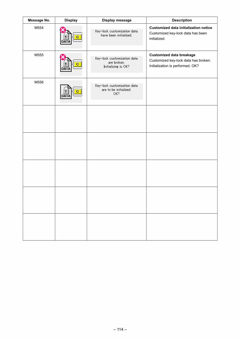
– 114 –
Message No. Display Display message Description
M554 Customized data initialization noticeCustomized key-lock data has been initialized.
M555 Customized data breakageCustomized key-lock data has broken. Initialization is performed. OK?
M556 Initialization confirmation of customized dataCustomized key-lock data is initialized. OK?
M557 Confirmation of clearance of password settingClears passwordYes or no
M653 During formattingFormatting is performed.
M669 During data readingData is being read.
M670 During data writingData is being written.
M671 During data convertingData is being converted.
– 115 –
1-1. Adjusting the height of the needle bar (Changing the length of the needle)
* Turn ON the power once, and turn OFF the power again after making the intermediate presser in the lowered state.
1) Bring needle bar ❶ down to the lowest position of its stroke. Loosen needle bar connection screw ❷ and adjust so that the upper marker line ❸ engraved on the needle bar aligns with the bottom end of the needle bar bushing lower ❹ .
2) As illustrated in the above figure, change the adjusting position in accordance with the needle count.
After the adjustment, turn the pulley to check for an extra load.
1. MAINTENANCE
❺ : Market line for DP x 17 (with needle count higher than #22)❻ : Marker line for DP x 17 (with needle count lower than #22)
III. MAINTENANCE OF SAWING MACHINE
WARNING : Turn OFF the power before starting the work so as to prevent accidents caused by abrupt start or
the sewing machine.
❶
❹ ❸
❺❻
❶
❷

– 116 –
1-2. Adjusting the needle-to-shuttle relation
WARNING : Turn OFF the power before starting the work so as to prevent accidents caused by abrupt start or
the sewing machine.
* Turn ON the power once, and turn OFF the power again after making the intermediate presser in the lowered state.
1) Loosen setscrews ❶ (right and left). Pull out oil shield ❷ toward you to remove it.
2) Loosen hinge screw ❸ . Remove thread trim-ming lever asm. ❹ .
3) Loosen four setscrews ❺ . Remove throat plate asm. ❻ .
4) Fix the lower shaft. Turn pulley ❾ while insert-ing hook driving shaft fixing rod ❽ into hook driving shaft fixing rod insertion hole ❼ until hook driving shaft fixing rod ❽ is brought to the position where it can be inserted deeply.
❶❷
❸❹
❺
❻
❼
❻
❺
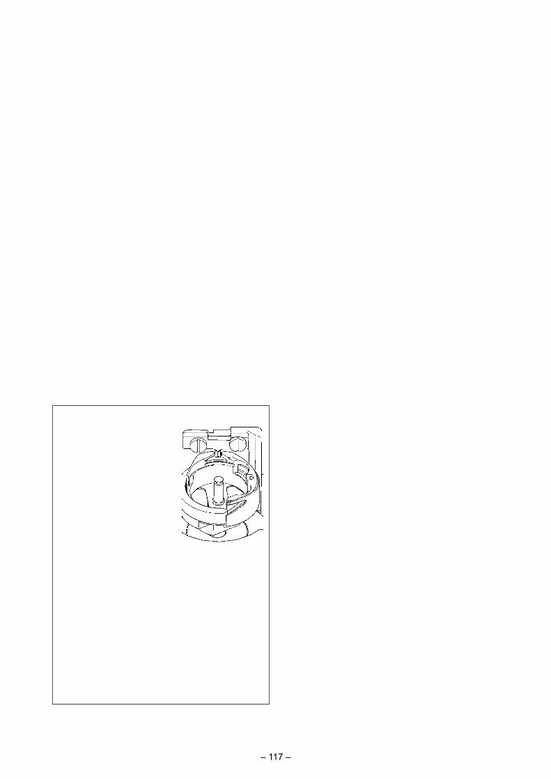
– 117 –
�
��
�
�
�
0.03 to 0.1 mm
5) Loosen hook setscrew � . Move the hook to adjust so that the blade point of hook is aligned with the center of needle.
6) Adjust the longitudinal position of the hook so that a clearance of 0.03 to 0.1 mm is provided between the needle and blade point � of hook when the blade point of hook is aligned with the center of needle. Then, tighten setscrew � .
When making the needle size thicker, confirm the clearance between the needle tip or the intermediate presser and the wiper. Wiper cannot be used unless the clearance is secured. In this case, turn OFF the wiper switch, or change the set value of memory switch .
Aligned
Needle
[ Adjusting the bobbin case holder position bracket ]
7) Loosen setscrews � of bobbin case holder position bracket � .
8) Move bobbin case holder position bracket � to the right or left to adjust so that the center of bobbin case holder position bracket � is aligned with the center of needle. Then, tight-en setscrews � .
9) Loosen setscrews � of bobbin case holder position bracket base � .
10) Move bobbin case holder position bracket base � back or forth to adjust so that the end face of bobbin case holder position bracket � is aligned with the end face of notch in the slot of bobbin case holder. Then, tighten setscrews � .
�
– 118 –
By removing the rubber plug in the face plate cover, adjustment can be performed without removing the face plate cover.
1-4. The moving knife and counter knife
Position of the moving knifeLoosen adjustment screw ❸. Move the moving knife in the direction of arrow to adjust so that the tip of thread trimming lever (small) ❷ is spaced 19.0 mm from the front end of throat plate ❶ be-fore the thread trimming operates (in the standby state).
Position of the counter knifeLoosen setscrew ❻. Move the counter knife so that a clearance of 1.5 mm is provided between needle hole guide ❹ and counter knife ❺.
WARNING : Turn OFF the power before starting the work so as to prevent accidents caused by abrupt start or
the sewing machine.
1-3. Adjusting the vertical stroke of the intermediate presser
* Turn ON the power once, and turn OFF the power again after making the intermediate presser in the lowered state.
1) Remove face cover.2) Turn handwheel to make the needle bar come
down to its lowest point.3) Loosen hinge screw ❶ and move it to the di-
rection A to increase the stroke.4) When marker dot A is aligned with the right
side of the outer periphery of washer ❷ , the vertical stroke of the intermediate presser becomes 4 mm. And, when marker dot B is aligned with the right side of the outer periphery of the washer, it becomes 7 mm. (The vertical stroke of the intermediate presser is factory-set to 4 mm at the time of delivery.)
WARNING : Turn OFF the power before starting the work so as to prevent accidents caused by abrupt start or
the sewing machine.
AB
❷
A
❶
❹❻ ❶
❺
❷
❶
❹
❻
❺
❸
19.0 mm
1.5 mm
– 119 –
1-5. Thread breakage detector plate
1) Adjust so that thread breakage detector plate ❶ is always in contact with thread take-up spring ❷ in the absence of needle thread. (Slack : approx. 0.5 mm)
2) Whenever the stroke of thread take-up spring ❷ has been changed, be sure to readjust thread breakage detector plate ❶ . To make this adjustment, loosen screw ❸ .
Adjust so that thread breakage detec-tor plate ❶ does not touch any adja-cent metallic parts other than thread take-up spring ❷ .
The oiling quantity can be reduced by tightening adjustment screw ❶.
1. In the standard adjustment state at the time of shipment, the position of adjustment screw ❶ has been adjusted by fully tightening it first, then loosening it by a half turn.
2. In the case you need to reduce the oiling quantity, do not tighten the adjustment screw fully at a time. Ex-cessively reducing the oiling quan-tity can cause the hook to wear.
1-6. Amount of oil supplied to the hook
❶
❸
❷
❶
❶
Periodically wipe oil shield ❶ to clean it up.
1-7. Periodical cleaning of the oil shield
For the adjusting the oil quantity in the hook, refer to the item of "I-4-2. Adjusting the oil quantity in the hook" p.16 .

– 120 –
1-8. Replacing the fuse
DANGER :1. To avoid electrical shock hazards, turn OFF the power and open the control box cover after about
five minutes have passed.2. Open the control box cover after turning OFF the power without fail. Then, replace with a new fuse
with the specified capacity.
Four fuses are used.❶ For the protection of the AC servomotor power 15A (time-lag fuse)❷ For pulse motor power supply protection 10A (time-lag fuse)❸ For control power supply protection 3.5A (time-lag fuse)❹ For solenoid and pulse motor power supply protection 10A (time-lag fuse)
❹ ❸
❷
❶
– 121 –
1. Error code E220 or E221 is displayed again unless UMBER OF STITCHES D is changed to "0" after replenishing the designated places with grease. When E221 is displayed, the sewing machine fails to operate. So, be careful.
2. When GREASE APPLYING POSITION DISPLAY but-
ton C is pressed in each screen, the grease
applying position can be confirmed in the panel display. Be sure, however, to perform the grease applying after turning OFF the power.
1-9. Replenishing the designated places with grease
C
B
C
B
* Perform grease supplement when the errors below are displayed or once a year (either one which is earlier).
If grease has decreased due to cleaning of the sewing machine or any other reasons, be sure to immediately add grease.
When the sewing machine has been used for a certain number of stitches, error "E220 Grease-up warning" is displayed. This display informs the operator of the time of replenishing the designated places with grease. Be sure to replenish the places with the grease below. Then call the memory switch , press CLEAR button
A and set NUMBER OF STITCHES D to "0".Even after the display of the error "E220 Grease-up warning",
when RESET key B is pressed, the error is released, and the sewing machine can be continuously used. Afterwards, howev-er, error code "E220 Grease-up warning" is displayed every time the power is re-turning ON.In addition, when the sewing machine is used further for a certain period of time without replenishing the places with grease after the display of error No. E220, error "E221 Grease-up error" is displayed and the sewing machine fails to operate since the error cannot be released even when the RESET key is pressed.
When error "E221 Grease-up error" is displayed, be sure to replen-ish the designated places below with grease. Then call the memo-
ry switch , press CLEAR button A and set NUMBER OF STITCHES D to "0".
When RESET key B is pressed without replenishing the designated places with grease, error code "E221 Grease-up warn-ing" is displayed every time the power is re-turning ON afterwards and the sewing machine fails to operate. So, be careful.
A
C
D

– 122 –
Use grease tube A (part number: 40006323) supplied with the unit for adding grease to any points other than the points specified below. If any grease other than the specified one is used, the related components can be damaged.
(1) Types of grease
Spare parts No.JUKI Grease A 10g tube 40006323
100g tube 23640204JUKI Grease B 10g tube 40013640
WARNING : Turn OFF the power before starting the work so as to prevent accidents caused by abrupt start
or the sewing machine. In addition, attach the covers which have been removed before operation back in place.
(2) Points to be applied with JUKI Grease A
❷❻
❻
❷
❼
❶
❽❾
❺❹
■ Adding grease to the needle bar upper and lower bushings section, slide block section and intermediate presser bar lower bushing section
1) Open the frame cover to remove intermediate presser auxiliary spring B ❶ .
2) Apply JUKI Grease A onto periphery of needle bar ❷ . Turn the sewing machine by hand to apply grease onto the entire periphery of the needle bar.
Turn needle bar upper bushing grease cover ❸ in the direction of arrow A to add grease through the grease inlet. After completion of the procedure, turn the needle bar upper bushing grease cover in the direction of arrow B to return to its home position.
Remove setscrew ❹ from the needle bar lower bushing grease hole. Put JUKI Grease A through hole ❺ and tighten setscrew ❹ to fill inside the busing with the grease.
3) Apply JUKI Grease A also onto groove section ❻ of the slide block.
4) Apply JUKI Grease A onto periphery of inter-mediate presser bar ❼ .
Remove setscrew ❽ from the intermediate presser bar bushing grease hole. Put JUKI Grease A through inlet ❾ . Tighten screw ❽ to fill inside the bushing with JUKI Grease A.
– 123 –
1. Do not wipe off the grease applied onto the periphery of needle bar inside the frame. If the grease has decreased due to cleaning, air blow or other reasons, apply grease again without exceptions.
2. When operating the sewing ma-chine, turn the needle bar upper bushing grease cover in direction B to close grease inlet � .
3. The rear face of the needle bar crank rod has projection � with a sharp edge. So, care should be tak-en to the projection. Never put your finger to the rear face of the needle bar crank rod during greasing pro-cedure.
B A
❸
�
�
❶❷
❻❼
❽❺
❹ ❸
■ Grease supplement to the face plate section
1) Open the face plate cover.2) Add the JUKI Grease B onto the felt sections
(3 locations), peripheral shoulder screw, ful-crums ❶ to ❼ and guide groove section ❽ .
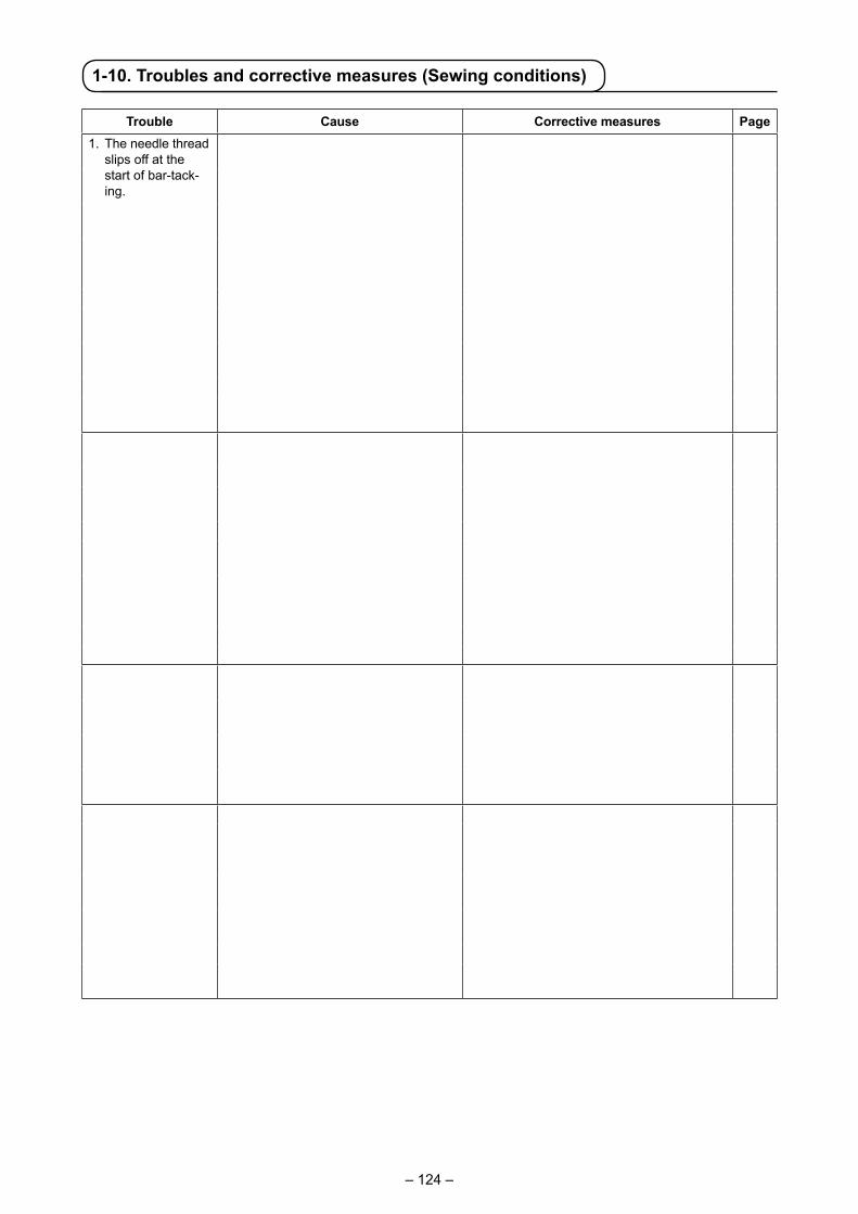
– 124 –
1-10. Troubles and corrective measures (Sewing conditions)
Trouble Cause Corrective measures Page1. The needle thread
slips off at the start of bar-tack-ing.
① Stitches are slipped at the start. ○ Adjust the clearance between the needle and the shuttle to 0.03 to 0.1 mm.
117
○ Set soft-start sewing at the start of bart-acking.
94
② The needle thread remaining on the needle after thread trimming is too short.
○ Correct the thread tension release timing of the thread tension controller No. 1.
○ Increase the tension of the thread take-up spring, or decrease the tension of the thread tension controller No. 1.
25,26
③ The bobbin thread is too short. ○ Decrease the tension of the bobbin thread. 25○ Increase the clearance between the nee-
dle hole guide and the counter knife.118
④ Needle thread tension at 1st stitch is too high.
○ Decrease the tension at 1st stitch.
⑤ Pitch at 1st stitch is too small. ○ Make the pitch at 1st stitch longer.○ Decrease the needle thread tension at
1st stitch.2. Thread often
breaks or syn-thetic fiber thread splits finely.
① The hook has scratches on it. ○ Take it out and remove the scratches using a fine whetstone or buff.
② The needle hole guide has scratches. ○ Buff or replace it.③ The needle strikes the intermediate
presser foot.○ Correct the position of the intermediate
presser foot.26
④ The needle thread tension is too high. ○ Reduce the needle thread tension. 25⑤ The tension of the thread take-up
spring is too high.○ Reduce the tension. 26
⑥ When taking up thread, thread is pierced with needle tip.
○ Lower the needle bar height from the engraved marker line by a half of the line to as much as the line.
○ Check the rough state of needle tip.○ Use the ball-pointed needle.
3. The needle often breaks.
① The needle is bent. ○ Replace the bent needle. 18
② The needle strikes the intermediate presser foot.
○ Correct the position of the intermediate presser foot.
26
③ The needle is too thin for the material. ○ Replace it with a thicker needle according to the material.
④ There is no clearance between the needle and hook.
○ Correctly position the needle and the shut-tle.
117
4. Threads are not trimmed.
① The counter knife is dull. ○ Replace the counter knife.② The difference in level between the
needle hole guide and the counter knife is not enough.
○ Increase the bend of the counter knife.
③ The moving knife has been improper-ly positioned.
○ Correct the position of the moving knife. 118
④ The last stitch is skipped. ○ Correct the timing between the needle and the shuttle.
117
(Bobbin thread only) ⑤ Bobbin thread tension is too low. ○ In crease the bobbin thread tension.⑥ Flopping of cloth. ○ Lower the intermediate presser height of
the last stitch.
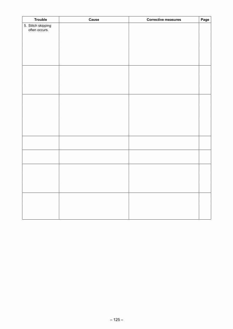
– 125 –
Trouble Cause Corrective measures Page5. Stitch skipping
often occurs.① The motions of the needle and shuttle
are not properly synchronized.◦ Correct the positions of the needle and
shuttle.117
② Clearance between the needle and hook is large.
◦ Correct the positions of the needle and shuttle.
117
③ The needle is bent. ◦ Replace the bent needle. 18④ Length of needle thread remaining after
thread trimming is too long. (In the case of stitch skipping within the 2nd to 10th stitch from the beginning of sewing)
◦ Reduce the thread take-up spring pressure or increase the thread tension applied by the thread tension controller No. 1.
25,26
6. The needle thread comes out on the wrong side of the material.
① The needle thread tension is not high enough.
◦ Increase the needle thread tension. 25
② The tension release mechanism fails to work properly.
◦ Check whether or not the tension disc No. 2 is released during bar-tracking.
③ The needle thread after thread trimming is too long.
◦ Increase the tension of the thread ten-sion controller No. 1.
25
7. Thread end of the 1st stitch comes out on the right side of the mate-rial.
① Stitch skipping at the 1st stitch. ◦ Adjust the hook timing faster by a 1/2 stitch.
② Needle used and thread used are thick in terms of the inner diameter of the intermediate presser.
◦ Increase the inner diameter of interme-diate presser.
③ Intermediate presser is not properly positioned in terms of the needle.
◦ Adjust the eccentricity between inter-mediate presser and needle so that needle enters in the center of interme-diate presser.
8. Threads break at time of thread trimming.
① The moving knife has been improperly position.
◦ Correct the position of the moving knife.
118
9. Uneven length of the needle thread.
① The tension of thread take-up spring is too low.
◦ Increase the tension of the thread take-up spring.
26
10. The length of needle thread does not become short.
① The tension of thread tension controller No. 1 is too low.
◦ Increase the tension of thread tension controller No. 1.
25
② The tension of thread take-up spring is too high.
◦ Decrease the tension of thread take-up spring.
26
③ The tension of thread take-up spring is too low and motion is unstable.
◦ Increase the tension of thread take-up spring and lengthen the stroke as well.
11. The knotting section of bobbin thread at 2nd stitch at the sew-ing start appears on the right side.
① Idling of bobbin is large. ◦ A just the position of the moving knife. 118② The bobbin thread tension is too low. ◦ Increase the bobbin thread tension. 25③ The needle thread tension at 1st stitch
is too high.◦ Decrease the needle thread tension at
1st stitch.
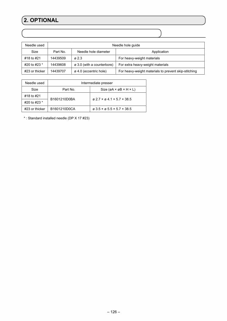
– 126 –
2. OPTIONAL
Needle used Needle hole guide
Size Part No. Needle hole diameter Application
#18 to #21 14439509 ø 2.3 For heavy-weight materials
#20 to #23 * 14439608 ø 3.0 (with a counterbore) For extra heavy-weight materials
#23 or thicker 14439707 ø 4.0 (eccentric hole) For heavy-weight materials to prevent skip-stitching
Needle used Intermediate presser
Size Part No. Size (øA × øB × H × L)
#18 to #21B1601210D0BA ø 2.7 × ø 4.1 × 5.7 × 38.5
#20 to #23 *
#23 or thicker B1601210D0CA ø 3.5 × ø 5.5 × 5.7 × 38.5
* : Standard installed needle (DP X 17 #23)・H type : Applicable count of thread : #30 to #05
H
Lø A
ø B
2-1. List of the needle hole guides and intermediate pressers

– 127 –
WARNING:• Do not look directly into the laser beam of the bar code reader. The laser beam can damage eyes.• Do not emit laser beam toward human eyes. The laser beam can damage eyes.• Do not look into the laser beam directly using an optical device. The laser beam can damage eyes.
CAUTION:• Be sure to use the sewing machine within the specified temperature range and the specified
humidity range.• Do not connect/remove connectors with the power supplied to the sewing machine.
2-2. Bar code reader
Bar code function is a function to read the bar code and to switch to the corresponding sewing pattern for the applications such as the cassette identification etc.By reading the bar code, switching to 999 user patterns stored in the sewing machine memory and to 50 sewing data registered in the pattern button can be made.To use this function, AMS-EN bar code option (40089238) will be required.Refer to the Instruction Manual/Parts List (40089259) for the Bar-code Reader (optional) of the AMS-EN Series for details.
Specifications for the barcode readerClass 2 laser productMaximum output: 1.0mWWave length: 650nm
Safety standardJIS C 6802:2005 IEC60825-1+A2:2007


![-HGQRGXFKpXSHYQ Qt]DFYDNiYDFtVSRQRX...Dräger Safety s.r.o. Obchodní 124 251 01 Čestlice Tel +420 272 011 852 Fax +420 272 767 414 prodej@draeger.com. Dräger - South East Europe](https://img.pdfslide.net/doc/110x75/6091ef046691ee5a3a745f73/-hgqrgxfkpxshyq-qtdfydniydftvsrqrx-drger-safety-sro-obchodn-124-251.jpg)