Embed Size (px)
Citation preview

7/29/2019 AMSTERDAM SAVUNMA HATTININ DÖNÜŞTÜRÜLMESİNDE KILAVUZ OLARAK EDİMSEL MİMARLIK
http://slidepdf.com/reader/full/amsterdam-savunma-hattinin-doenuestueruelmesinde-kilavuz-olarak-edimsel 1/121
i
PERFORMATIVE ARCHITECTURE AS A GUIDELINE FOR TRANSFORMATION OF THE DEFENCE LINE OF AMSTERDAM
A THESIS SUBMITTED TO
THE GRADUATE SCHOOL OF NATURAL AND APPLIED SCIENCES
OF
MIDDLE EAST TECHNICAL UNIVERSITY
BY
CANAN ALBAYRAK
IN PARTIAL FULFILLMENT OF THE REQUIREMENTS FOR
THE INTERNATIONAL JOINT DEGREE OF MASTER OF SCIENCE
IN
THE DEPARTMENT OF ARCHITECTURE
IN
COMPUTATIONAL DESIGN AND FABRICATION
TECHNOLOGIES IN ARCHITECTURE
BY
MIDDLE EAST TECHNICAL UNIVERSITY
DELFT UNIVERSITY OF TECHNOLOGY
JANUARY 2011

7/29/2019 AMSTERDAM SAVUNMA HATTININ DÖNÜŞTÜRÜLMESİNDE KILAVUZ OLARAK EDİMSEL MİMARLIK
http://slidepdf.com/reader/full/amsterdam-savunma-hattinin-doenuestueruelmesinde-kilavuz-olarak-edimsel 2/121
ii
Approval of the thesis:
PERFORMATIVE ARCHITECTURE AS A GUIDELINE FOR TRANSFORMATION OF THE DEFENCE LINE OF AMSTERDAM
submitted by CANAN ALBAYRAK in partial fulfillment of the requirements for the
degree of Master of Science in Architecture Department, Middle East Technical University, and Delft University of Technology by,
Prof. Dr. Canan Özgen ____________________
Dean, Graduate School of Natural and Applied Sciences
Assoc. Prof. Dr. Güven Arif Sargın ____________________ Head of Department, Architecture
Prof. Dr. Can Baykan ____________________ Supervisor, Architecture Dept., METU
Examining Committee Members:
Assoc. Prof. Dr. Arzu Gönenç Sorguç ____________________ Architecture Dept., METU
Prof. Dr. Can Baykan ____________________
Architecture Dept., METU
Assoc. Prof. Dr. Rudi Stouffs ____________________
Building Technology Dept., TU Delft
Assist. Prof. Dr. Bige Tunçer ____________________ Building Technology Dept., TU Delft
Assist. Prof. Ir. Huib Plomp ____________________ Building Technology Dept., TU Delft
Date: 28/01/2011

7/29/2019 AMSTERDAM SAVUNMA HATTININ DÖNÜŞTÜRÜLMESİNDE KILAVUZ OLARAK EDİMSEL MİMARLIK
http://slidepdf.com/reader/full/amsterdam-savunma-hattinin-doenuestueruelmesinde-kilavuz-olarak-edimsel 3/121
iii
I hereby declare that all information in this document has been obtained and presented in accordance with academic rules and ethical conduct. I also declare that, as required by these rules and conduct, I have fully cited and referenced all material and results that are not original to this work.
Name, Last Name: CANAN ALBAYRAK
Signature :

7/29/2019 AMSTERDAM SAVUNMA HATTININ DÖNÜŞTÜRÜLMESİNDE KILAVUZ OLARAK EDİMSEL MİMARLIK
http://slidepdf.com/reader/full/amsterdam-savunma-hattinin-doenuestueruelmesinde-kilavuz-olarak-edimsel 4/121
iv
ABSTRACT
PERFORMATIVE ARCHITECTURE AS A GUIDELINE FOR TRANSFORMATION OF THE DEFENCE LINE OF AMSTERDAM
Albayrak, Canan
International Joint M.S. Programme of Computational Design and
Fabrication Technologies in Architecture, Department of
Architecture
Supervisor: Prof. Dr. Can Baykan
January 2011, 107 pages
The main topic that is researched in this study is: what performative architecture is and
its role in the design process and product. In the scope of performative architecture the
aim is to focus what a building does rather than what it is and the fact that architecture
should
have
the
capability
of
being
adaptable
to
changing
time,
conditions
and
environment. A design problem is taken under consideration and designed from the
scope of performative architecture. The design problem is the transformation of the
Defence Line around Amsterdam, designing new buildings with the recent technologies as
additions to the forts remaining from 1900’s. A “performative model”, which supports
design from the conceptual stage until production of scale prototypes is structured by the
author for this specific design problem. This performative model is used as a case study
for the research of the role of the computational design tools in the design process and
product of performative architecture. In addition to the design process, the role of using
computer‐aided manufacturing to increase performativity is envisioned and the proceeds
of it to the relationship of design is also researched.
Keywords: Performative Architecture, Performance Evaluation, Parametric Modelling,
Computational Design Tools, Computer Aided Manufacturing

7/29/2019 AMSTERDAM SAVUNMA HATTININ DÖNÜŞTÜRÜLMESİNDE KILAVUZ OLARAK EDİMSEL MİMARLIK
http://slidepdf.com/reader/full/amsterdam-savunma-hattinin-doenuestueruelmesinde-kilavuz-olarak-edimsel 5/121
v
ÖZ
AMSTERDAM SAVUNMA HATTININ DÖNÜŞTÜRÜLMESİNDE KILAVUZ OLARAK EDİMSEL MİMARLIK
Albayrak, Canan
Mimarlıkta Sayısal Tasarım ve Üretim Teknolojileri Uluslararası Ortak
Yüksek Lisans Programı, Mimarlık EABD
Tez Yöneticisi: Prof. Dr. Can Baykan
Ocak 2011, 107 sayfa
Bu çalışmada öncelikli olarak edimsel mimarlığın ne olduğu, tasarım sürecindeki ve
sonucundaki rolü incelenmiştir. Edimsel mimarlık kapsamında binanın ne olduğu değil ne
yaptığı üzerine odaklanıp mimarlığın zamana, şartlara ve çevreye adapte olabilmesi
özelliğine sahip olması amaçlanmıştır. Bir tasarım sorunu edimsel mimarlık kapsamında
ele alınıp, tasarlanmıştır. Tasarım sorunu Amsterdam etraf ındaki savunma hattının
dönüşümü, 1900lerden kalma kalelere ek olarak günümüz teknolojilerini yansıtan ek
binalar tasarlanmasıdır. Tasarımı konsept aşamasından ölçekli prototip oluşturma
aşamasına kadar destekleyen bir “edimsel model” bu belirli tasarım problemi için yazar
taraf ından oluşturuldu. Bu edimsel model sayısal tasarım araçlarının, edimsel mimarlığın
tasarım süreci ve sonucundaki rollerini araştırmak için örnek incelemesi olarak
kullanılmıştır. Tasarım sürecine ek olarak, üretim aşamasındaki bilgisayar destekli üretim
sistemlerinin kullanımının edimselliği arttırmadaki rolü de öngörülüp, tasarım ve üretim
ilişkisine getirileri inceleniştir.
Anahtar Kelimeler: Edimsel Mimarlık, Performans Değerlendirmesi, Parametrik
Modelleme, Sayısal Tasarım Araçları, Bilgisayar Destekli Üretim

7/29/2019 AMSTERDAM SAVUNMA HATTININ DÖNÜŞTÜRÜLMESİNDE KILAVUZ OLARAK EDİMSEL MİMARLIK
http://slidepdf.com/reader/full/amsterdam-savunma-hattinin-doenuestueruelmesinde-kilavuz-olarak-edimsel 6/121
vi
To my grandfather Kazım Albayrak

7/29/2019 AMSTERDAM SAVUNMA HATTININ DÖNÜŞTÜRÜLMESİNDE KILAVUZ OLARAK EDİMSEL MİMARLIK
http://slidepdf.com/reader/full/amsterdam-savunma-hattinin-doenuestueruelmesinde-kilavuz-olarak-edimsel 7/121
vii
ACKNOWLEDGMENTS
I wish to express my sincere gratefulness to my thesis supervisor, Prof. Dr. Can Baykan,
for his guidance and contributions throughout this study.
I would also like to thank my jury members Prof. Dr. Can Baykan , Assoc. Prof. Dr. Arzu
Gönenç Sorguç, Assoc. Prof. Dr. Rudi Stouffs, Assist. Prof. Dr. Bige Tunçer, and Assist.
Prof. Ir. Huib Plomp for their valuable critics, suggestions and comments.
I would also offer sincere thankfulness to my studio tutors, for the graduation project in
TU Delft: Ir. Huib Plomp, Dr.ir. Bige Tunçer, and Ir. Sander Mulders for their encouraging
criticisms and meaningful guidance.
I wish to express a very special appreciation to Dr.ir. Rudi Stouffs, as the program
coordinator, and Dr.ir. Bige Tunçer. Their endless support and mentoring was precious,
and to them I owe deep gratitude.
I would like to thank to my family, my parents Neslihan and Ertuğrul Albayrak and my
sister Ceren Albayrak, for their support and encouragement in all aspects of life. My
gratitude can never be enough.
Finally, I am grateful to Rui Colaço for his continuous support and motivation in all terms.

7/29/2019 AMSTERDAM SAVUNMA HATTININ DÖNÜŞTÜRÜLMESİNDE KILAVUZ OLARAK EDİMSEL MİMARLIK
http://slidepdf.com/reader/full/amsterdam-savunma-hattinin-doenuestueruelmesinde-kilavuz-olarak-edimsel 8/121
viii
TABLE OF CONTENTS
ABSTRACT....................................................................................…………………...................iv
ÖZ....................................................................................................………………................. v
ACKNOWLEDGMENTS ...................................................................…………………...............vii
TABLE OF CONTENTS......................................................................…………………............. viii
LIST OF TABLES ...............................................................................………………….............. xi
LIST OF FIGURES ..........................................................................………………...................xii
CHAPTER
1‐INTRODUCTION……………………………………………………………………………………………………..…..1
2‐ CATEGORIZATION OF DIGITAL MODELS…………………………………………………………………….4
2.1. CAD models………………………………………………………………………………………..………4
2.1.1M.art.A. Museum…………………………………………….………………….…..…..5
2.1.2 Kunsthaus Graz…………………………………………..…..…………………………..6
2.2 Formation Models………………………………………………………….…………………………..8
2.2.2 Dynaform BMW Pavilion………………………………..……………………..…….8
2.3 Generative Models……………………………………………………….…………………………..10
2.4 Performance Models………………………………………………………………………………...11
2.4.1 Performance based formation models……………..……………………....13
2.4.1.1 City Hall………………………………………………………….13
2.4.2 Performance based generation models……………………………………..15
2.4.2.1 Port Authority Gateway…………………………….…..15
3‐ PERFORMATIVE DESIGN…………………………………………………………………………………….……17
3.1 Performative Design as a technical development……………………………………..17
3.1.1 Morpho‐Ecological Approach for Design……………….…………………..18

7/29/2019 AMSTERDAM SAVUNMA HATTININ DÖNÜŞTÜRÜLMESİNDE KILAVUZ OLARAK EDİMSEL MİMARLIK
http://slidepdf.com/reader/full/amsterdam-savunma-hattinin-doenuestueruelmesinde-kilavuz-olarak-edimsel 9/121
ix
3.2 Performative Design as a shift of orientation in architecture. ……………………19
3.2.1 Performance as controlling the unbuilt ……………………………………..20
3.2.1.1.Louvre Museum……………………………………………………….…21
3.2.2 Architecture as performance……………………………………………………..23
3.2.2.1.D‐Tower……………………………………………………………………..24
3.2.2.2 Kunsthaus Graz…………………………………………………………..25
3.2.3 Movement as Performance ……………………………………………………….26
3.2.3.1 Filamentosa …………………………………………………………….…26
3.3 Definition of performative architecture ……………………………………………………28
4‐ PERFORMANCE ASSESSMENT……………………………………………………………………………..…..30
4.1 Building performance evaluation levels…………………………………………………..…30
4.2 Review of Projects That Are Related With Digital Models………………………….32
4.3 Categorization of architectural performances……………………………………….….34
4.4 Computational Tools Related with Performance …………………………………..….34
4.4.1 Analytical …………………………………………………………………………………..35
4.4.2 Generative……………………………………………………………………………..….40
4.4.3 Performative………………………………………………………………………………42
4.4.4 Need for yet to be Made Tools…………………………………………………..44
5‐ GENERAL CHARACTER OF THE DEFENCE LINE AND ITS TRANSFORMATION………………………………………………………………………………………………….….46
5.1 Today and Future of the Defence Line……………………………………………………..…49
5.2 Computing Urbanization Levels for Each Site…….……………………………….………52
5.3 Defining New Functions and Additions………………………………………………….…..58
5.4 Defining Performance Criteria……………………………………………………………….…..60

7/29/2019 AMSTERDAM SAVUNMA HATTININ DÖNÜŞTÜRÜLMESİNDE KILAVUZ OLARAK EDİMSEL MİMARLIK
http://slidepdf.com/reader/full/amsterdam-savunma-hattinin-doenuestueruelmesinde-kilavuz-olarak-edimsel 10/121
x
5.4.1 Structural Performance……………………………………………………………...62
5.4.2 Illuminative Performance …………………………………………………….…….66
5.5.4.1 Woody Plants……………………………………………………………...67
5.5.4.2 Grassland…………………………………………………………………….67
5.5.4.3 Water Bodies…………………………………………………………..…..68
5.5.4.4 Micro climates………………………………………………………….….68
6‐ PERFORMATIVE DESIGN MODEL……………………………………………………………………………….70
6.1 Parameterization and Articulation of the Model ……….……………………………….71
6.1.1 Regional Design Stage………………………………….………………………………73
6.1.2 Urban Design Stage……………………………………………………………….…….74
6.1.3 Building Design Stage…………………………………………………………………..76
6.1.3.1 Computing Catenary Arches…………………………………………76
6.1.3.2 Computing Sunlight Angles……………….………………………….79
6.1.4 Production of Scale Models Stage…………………………………………………81
6.2 “Instances Set One” ………………………………………………………………………………..….83
6.3 “Instances Set Two” …………………………………………………………………………..……….91
7 –CONCLUSION…………………………………………………………………………………………………………….99
REFERENCES…………………………………………………………………………………………………………..…….105

7/29/2019 AMSTERDAM SAVUNMA HATTININ DÖNÜŞTÜRÜLMESİNDE KILAVUZ OLARAK EDİMSEL MİMARLIK
http://slidepdf.com/reader/full/amsterdam-savunma-hattinin-doenuestueruelmesinde-kilavuz-olarak-edimsel 11/121
xi
LIST OF TABLES
TABLES
Table 1: categorization of architectural performances ...................................................... 34
Table 2: correspondence between building performance assessment levels and
performance focus in each stage........................................................................................ 72
Table 3: program for botanical garden ............................................................................... 86

7/29/2019 AMSTERDAM SAVUNMA HATTININ DÖNÜŞTÜRÜLMESİNDE KILAVUZ OLARAK EDİMSEL MİMARLIK
http://slidepdf.com/reader/full/amsterdam-savunma-hattinin-doenuestueruelmesinde-kilavuz-olarak-edimsel 12/121
xii
LIST OF FIGURES
FIGURES
Figure 1: Museum for Furniture, Culture and Fine Arts ....................................................... 6
Figure 2: Kunsthaus Graz ...................................................................................................... 7
Figure 3: Dynaform BMW Pavilion...................................................................................... 10
Figure 4: Diagrammatic sumarry of the processes to reach convergence of form and
function............................................................................................................................... 12
Figure 5: City Hall London ................................................................................................... 14
Figure 6: Port Authority Gateway ....................................................................................... 16
Figure 7: Louvre Museum Abu Dhabi ................................................................................. 22
Figure 8: D‐Tower................................................................................................................ 24
Figure 9: BIX‐Performative skin of Kunsthaus..................................................................... 25
Figure 10: Filamentosa........................................................................................................ 27
Figure 11: Computational fluid dynamics simulations........................................................ 37
Figure 12: Finite element analysis ...................................................................................... 38
Figure 13: Project ZED......................................................................................................... 39
Figure 14: eifForm developed by Shea ............................................................................... 41
Figure 15: a Morpho‐Ecological approach for Design......................................................... 43
Figure 16 Defence Line of Amsterdam ............................................................................... 46
Figure 17: Elements of forts................................................................................................ 47
Figure 18: Photos of the forts ............................................................................................. 48
Figure 19: Section and front views of the forts .................................................................. 49
Figure 20: Recent situation of the forts along with photos of some recent functions attributed to them .............................................................................................................. 51
Figure 21: Conceptual design for the one of the future scenario for Randstad................. 51

7/29/2019 AMSTERDAM SAVUNMA HATTININ DÖNÜŞTÜRÜLMESİNDE KILAVUZ OLARAK EDİMSEL MİMARLIK
http://slidepdf.com/reader/full/amsterdam-savunma-hattinin-doenuestueruelmesinde-kilavuz-olarak-edimsel 13/121
xiii
Figure 22: satellite views of some forts .............................................................................. 52
Figure 23: different inputs to calculate the urban levels for the region of Defence Line .. 54
Figure 24: different influences of the controls ‘area of influence’ and ‘strength’ ............. 55
Figure 25: different definitions of ‘area of influence’ and ‘strength’ for different inputs 56
Figure 26: process for the waterlines ................................................................................. 57
Figure 27: final output of the model................................................................................... 58
Figure 28: the camouflage of the fort as an inspiration for the design.............................. 60
Figure 29: graph of catenary equation ............................................................................... 63
Figure 30: photo of Taq‐i Kisra............................................................................................ 64
Figure 31: run 1,3 and Run 2,4............................................................................................ 64
Figure 32: results of bending moment and axial force ...................................................... 65
Figure 33: stresses .............................................................................................................. 66
Figure 34: categorization of plants according to their optimum sunlight requirement..... 69
Figure 35: summary of the process for the first stage of model ........................................ 73
Figure 36: relationship between fort and addition, different configuration of masses
according to desired relationships and connections between elements ........................... 74
Figure 37: satellite views of forts........................................................................................ 75
Figure 38: output of catenary definition............................................................................. 77
Figure 39: process for different collection of line segments .............................................. 78
Figure 40: definition of support points and height of the arches....................................... 79
Figure 41: output of the model positioning of the sun through a year............................. 80
Figure 42: niches on the site to ease assembling ............................................................... 81
Figure 43: process for different collection of line segments .............................................. 82
Figure 44: the preliminary dependency chain .................................................................... 83
7/29/2019 AMSTERDAM SAVUNMA HATTININ DÖNÜŞTÜRÜLMESİNDE KILAVUZ OLARAK EDİMSEL MİMARLIK
http://slidepdf.com/reader/full/amsterdam-savunma-hattinin-doenuestueruelmesinde-kilavuz-olarak-edimsel 14/121
xiv
Figure 45: diagrammatic summary of process for stage one ............................................ 85
Figure 46: bubble diagram of program elements and relationships between them.......... 86
Figure 47 diagrammatic summary of process for stage two .............................................. 88
Figure 48: diagrammatic summary of process for level 1‐stage three and physical
model ................................................................................................................................. 89
Figure 49: diagrammatic summary of process for level two stage three ........................... 90
Figure 50: the improved dependency chain ....................................................................... 92
Figure 51: diagrammatic summary of process for stage two ............................................. 93
Figure 52: diagrammatic summary of process for level two stage three ........................... 95
Figure 53: diagrammatic summary of process for level 1‐stage three and physical
model .................................................................................................................................. 96
Figure 54: (continued) diagrammatic summary of process for level 1‐stage three and
physical model .................................................................................................................... 97
Figure 55: assembling of pieces of the physical model ...................................................... 98
Figure 56: photos of the forts from the Cascais coastline ................................................ 103
Figure 57: satellite view of the fort along the coast of Cascais ........................................ 103

7/29/2019 AMSTERDAM SAVUNMA HATTININ DÖNÜŞTÜRÜLMESİNDE KILAVUZ OLARAK EDİMSEL MİMARLIK
http://slidepdf.com/reader/full/amsterdam-savunma-hattinin-doenuestueruelmesinde-kilavuz-olarak-edimsel 15/121
1
CHAPTER 1
INTRODUCTION
Development of new instruments and methods redefine the practice and theory of
architecture. They contribute to a new understanding of the way buildings are imagined,
constructed and experienced. In the digital age, buildings give more difficult messages.
Rather than a call for aesthetics, buildings request the understanding of their
functionality and its reason (Hagan 2008). Due to the recent developments, technology,
cultural theory
and
the
emergence
of
sustainability
as
a defining
socio
‐economic
issue,
there is an increasing interest in performance as a design paradigm (Kolarevic 2005).
Architecture is a material practice. Therefore, it performs its social, cultural and ecological
relevance through its material arrangements and structure. How we (re)think
architecture is presented through the way we conceptualize these material interventions
and the technology that enables their construction. Over a number of decades the
progress of
Cad/Cam
is
groundbreaking.
The
inertia
in
design
thinking
in
the
context
of
technological progress should lead to a rethinking of architecture and its materialization
(Menges and Hensel 2008). These developing technologies together with accelerated
global urbanisation and climate change have increased the important role of
performative design.
Being performative is usually associated with environmental sustainability and complex
digital models analyzing the environmental behaviours of the buildings. This is limiting
performance only to a technical interpretation. Structural and environmental
performances are, with no doubt, obvious criteria for categorization as performative.
However, several other aspects are included: social, cultural, semiotic, basic (shelter) and
contrarian ones. Architecture has always performed socially, semantically, basically and
ideologically (Hagan 2008). Therefore, what is architectural performance in the digital
age? Is it like a performance of a car’s engine or like the performance that could be seen

7/29/2019 AMSTERDAM SAVUNMA HATTININ DÖNÜŞTÜRÜLMESİNDE KILAVUZ OLARAK EDİMSEL MİMARLIK
http://slidepdf.com/reader/full/amsterdam-savunma-hattinin-doenuestueruelmesinde-kilavuz-olarak-edimsel 16/121
2
on the theatrical stage?” There is no single answer for this question because of the
multiplicity of the meanings of the word performance.
performance
(a) the execution of an action; (b) something accomplished
fulfilment of a claim, promise, or request
the action of representing a character in a play; (c) a public presentation or exhibition
(d) the ability to perform; (e) the manner in which a mechanism performs
the manner of reacting a stimuli (Merriam Webster’s dictionary)
Within the scope of this thesis, performative architecture is the shift in the orientation of
architectural theory and practice from what the building is to what it does. Therefore, it
defines the architectural object, not by how it appears, but rather by its capability of
affecting, transforming and doing; in other words, by how it performs. It uses digital
generation and modification to search for design alternatives. The generated emergent
effects of the architecture (on nature, site, people, climate and time) are analyzed both
qualitatively and quantitatively in performative architecture.
Different architects
have
different
approaches
to
performative
architecture;
therefore
in
order to understand these redefinitions in architectural theory, it is necessary to do a re‐
examination of current design theories and methodologies. For this reason the literature
research of this thesis starts with categorization of digital models to form a background
(Chapter 2). Secondly, the study specifically based on performative architecture is
presented in Chapter 3. This is done by classifying the different approaches towards
performative architecture and reviewing the literature related with them; moreover a
selection
of
buildings
related
with
performativity
is
explored
to
express
the
wide
span
of
performative architecture.
A definition is not enough to address performative architecture as a guideline. The
criteria for performance assessment and variety of the tools should be studied, because
in architectural theory building performance assessment lacked a coherent basis
multidisciplinary research until recently. A general theoretical framework for
7/29/2019 AMSTERDAM SAVUNMA HATTININ DÖNÜŞTÜRÜLMESİNDE KILAVUZ OLARAK EDİMSEL MİMARLIK
http://slidepdf.com/reader/full/amsterdam-savunma-hattinin-doenuestueruelmesinde-kilavuz-olarak-edimsel 17/121
3
performance assessment is presented in Chapter 4 using a taxonomy of building
performance criteria and computational tools.
In consequence
of
the
research
summarized
above,
this
thesis
deals
with
performative
architecture to address a guideline for generation of design alternatives for a current
design problem of Dutch Landscapes. This design problem is the transformation of the
Defence Line of Amsterdam. This transformation includes conservation of 41 forts,
assigning them new functions and designing additions. In Chapter 5 general information
about historic and recent situation of Defence Line is presented along with the author’s
conceptual ideas about the transformation.
A “performative model”, which supports design from conceptual stage until production of
scale prototypes, is structured by the author for this specific design problem. This
performative model is used as a case study for the research of the role of the
computational design tools in the design process and product of performative
architecture. In Chapter 6 offers the details of the “performative model”. This study
specifically focuses on a design problem which involves of the transformation of an
element of the cultural heritage; thus the potential of performative design is explored as
a digital
design
methodology
to
redesign
historic
artefacts
(in
this
case
historic
forts,
landscape and water elements). In other words it is an experimental work to combine
developing technologies with cultural heritage.

7/29/2019 AMSTERDAM SAVUNMA HATTININ DÖNÜŞTÜRÜLMESİNDE KILAVUZ OLARAK EDİMSEL MİMARLIK
http://slidepdf.com/reader/full/amsterdam-savunma-hattinin-doenuestueruelmesinde-kilavuz-olarak-edimsel 18/121
4
CHAPTER 2
CATEGORIZATION OF DIGITAL MODELS
Digital design and its growing impact on design and production practices have resulted in
redefinitions of architectural theory such as performative architecture. Therefore, in
order to understand, explain, and guide future research and development in performative
architecture, it is necessary to do a re‐examination of current design theories and
methodologies.
Oxman categorizes
digital
models
in
the
following
classes:
1‐CAD models
2‐Formation Models
3‐Generative Models
4‐Performance Models
This categorization proposes the requirements for a conceptual framework and
theoretical
basis
of
digital
design;
it
reviews
a
basic
background
and
the
recent
theories;
moreover it defines a generic schema of design characteristics through which the
paradigmatic classes of digital design are formulated. The effects of digital techniques on
the processes, which are related to basic components of design, are identified. The
categorization of the models is based on the explications and relationships between basic
components of design which are representation, generation, performance and evaluation
(Oxman 2006).
2.1 CAD models
Traditional CAD models are commonly used for controlling graphical representations of
digital objects. Firstly, CAD technologies enable data flow between digital and physical
objects. By means of using various digital material processing techniques, data can be
transferred from digital models to physical objects and vice versa, such as translating

7/29/2019 AMSTERDAM SAVUNMA HATTININ DÖNÜŞTÜRÜLMESİNDE KILAVUZ OLARAK EDİMSEL MİMARLIK
http://slidepdf.com/reader/full/amsterdam-savunma-hattinin-doenuestueruelmesinde-kilavuz-olarak-edimsel 19/121
5
psychical objects into digital models. Eventually, Cad models create a seamless
integration of virtual and material (Kolarevic 2003).
Secondly, they
are
also
used
in
evaluative
analytical
processes,
e.g.
related
with
cost
estimation, structural behaviour, and environmental performance. They are used to
integrate advanced construction level modelling and evaluation software. This is achieved
through different stages of design. They help to support collaboration among different
design team groups, such as combinations of architects and engineers. However, in this
kind of models, generation is not explicit. Generation, representation and evaluation take
place consequently, not simultaneously. They are not directly linked, which means any
change and modification in digital model requires a re‐evaluation. Manipulations and
transformations needed to be employed manually for representation and evaluation
processes (Oxman 2006).
Various designers have experimented with this approach. For instance the design
processes of M.art.A. Museum and Kunsthaus Graz demonstrate the integration of virtual
and material, how CAD technologies enable data flow between digital and physical
models.
2.1.1 M.art.A. Museum, (Museum for Furniture, Culture and Fine Arts), (2000–2004),
Herford, Germany, Gehry Partners, LLP
M.art.A. Museum in Germany is a museum for art, design, fashion and architecture
(Figure 1a). The fundamental design strategy involved the incorporation of an existing
building with new buildings. Design did not have its genesis in a virtual environment.
Gehry manually built a series of physical models to explore the relationships between the
existing building and the new buildings as shown in Figure 1b. He focused on the effects
of the exterior surface and the interior spaces. Afterwards, these models were three
dimensionally digitized using CAD technologies. In Figure 1c the digital models are
illustrated. Catia, software was used for precise three‐dimensional models. This digital
model was used to correct and check the shape with respect to the site and program.
Having more accurate data was important to create a precise form fitting the existing

7/29/2019 AMSTERDAM SAVUNMA HATTININ DÖNÜŞTÜRÜLMESİNDE KILAVUZ OLARAK EDİMSEL MİMARLIK
http://slidepdf.com/reader/full/amsterdam-savunma-hattinin-doenuestueruelmesinde-kilavuz-olarak-edimsel 20/121
6
building. From these digitized data, more accurate physical models were created in order
to explore the shape in more detail (Kloft 2005).
Figure 1: Museum for Furniture, Culture and Fine Arts a‐ photos of the building (http://www.arcspace.com/architects/gehry/herford/ Last accessed 10 January 2011) b‐ physical models (http://www.arcspace.com/architects/gehry/herford/ Last accessed 10 January 2011) c‐ digital models: 3d model for buildings geometry, the architectural non‐structural skin, structural system
(Kloft, H. (2005). Non‐standard structural Design for Non‐Standard Architecture. Performative Architecture Beyond Instrumentality. B. Kolarevic and A. M. Malkawi, Spon Press: 135‐148)
Works of Frank Gehry are recognized for their contribution to the development of design
methodology. He was the first one to introduce Catia software, which is a parametric 3D
modelling programme mainly used in aerospace industry, to building design. In his design
process, he applied a dual‐directional relationship between physical and digital models.
2.1.2 Kunsthaus Graz, Graz, Austria, (2003), Peter Cook and Colin Fournier
Kunsthaus Graz Museum, shown in photos in Figure 2a, was built as part of the European
Capital of Culture celebrations in 2003. It is placed in a site containing a productive
dialogue between tradition and the avant‐garde. Consequently, the Kunsthaus functions
as a bridgehead at a point where the past and the future meet.

7/29/2019 AMSTERDAM SAVUNMA HATTININ DÖNÜŞTÜRÜLMESİNDE KILAVUZ OLARAK EDİMSEL MİMARLIK
http://slidepdf.com/reader/full/amsterdam-savunma-hattinin-doenuestueruelmesinde-kilavuz-olarak-edimsel 21/121
7
The conceptual design phase did not rely on computers heavily. The initial design for the
competition was created by making a handmade physical model (Figure 2b). This model
was three‐dimensionally scanned to produce an initial 3D model for design development.
The resultant
digital
model
is
accomplished
as
illustrated
in
Figure
2c;
however
architects
and engineers have decided to generate a new 3D models (Figure 2d) when they
considered the form optimization both structurally and in its materials. Rhinoceros 3D
modelling software was used for the new model, which closely followed the shape
proposed by the physical model without directly containing digital data taken from it. The
generation process did not end up with a rigid master geometry. The geometry was open
to optimization while still capturing the design intent of the original scheme.
Consequently, the structural behaviour was allowed to have influence on the final
geometry (Kloft 2005).
Figure 2: Kunsthaus Graz a‐ photos of the building (http://www.arcspace.com/architects/cook/ Last accessed 10 January 2011) b‐ handmade physical model (Kloft, H. (2005). Non‐standard structural Design for Non‐Standard Architecture.
Performative Architecture
Beyond
Instrumentality.
B.
Kolarevic
and
A.
M.
Malkawi,
Spon
Press:
135
‐148)
c‐ early computer rendering from the digital model accomplished by scanning the physical model (Kolarevic, B. (2005). Computing the Performative. Performative Architecture Beyond Instrumentality. B. Kolarevic and A. M. Malkawi, Spon Press: 193‐202.) d‐ digital models generated by engineers digital design model, the finite element analysis of complexly shaped skin, triangulated structural engineering pattern (Kloft, H. (2005). Non‐standard structural Design for Non‐Standard Architecture. Performative Architecture Beyond Instrumentality. B. Kolarevic and A. M. Malkawi, Spon Press: 135‐148)

7/29/2019 AMSTERDAM SAVUNMA HATTININ DÖNÜŞTÜRÜLMESİNDE KILAVUZ OLARAK EDİMSEL MİMARLIK
http://slidepdf.com/reader/full/amsterdam-savunma-hattinin-doenuestueruelmesinde-kilavuz-olarak-edimsel 22/121
8
2.2 Formation Models
Formation models are different from CAD models in their use in the representation
process. Digital
formation
models
are
much
more
than
static
abstractions
of
formal
representations. The use of dynamic concepts in digital design helps creating a new
definition for the role of the representation itself. Advancements in digital design not only
transform design representation but the design thinking as well. The concept of form is
thus transformed into the concept of formation. In formation models, digital techniques
are used in the generation of form and shape. In contrast, CAD models are only used for
representation and data flow. Designer operates the non deterministic logic of form
generation process along with digital techniques, such as scripting and parametric design.
The designer becomes a digital toolmaker for form generation.
Formative models concern design of the topology, which consists in the study of
relational structure of objects rather than studying its geometry. Properties of the objects
do not change when homeomorphic transformations are applied (Oxman 2006).
Dynaform designed by Bernhard Franken demonstrates how the dynamics of forces
produce the
motion
and
particular
transformation
of
from;
therefore
his
project
demonstrates an example for the formation models.
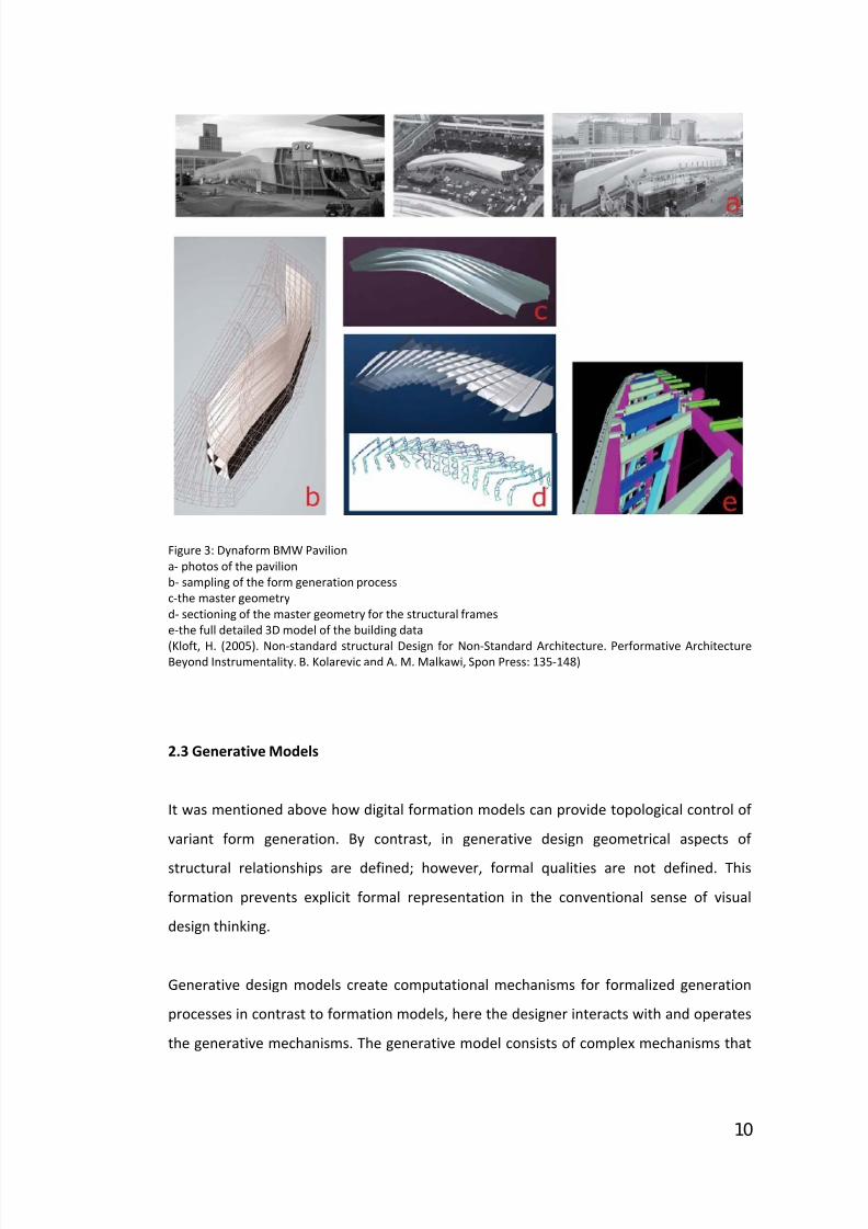
2.2.1 Dynaform BMW Pavilion, (2001), Frankfurt, Germany, Bernhard Franken and ABB
ArchitektenI7
Dynaform, designed by Bernard Franken, is an example of how the dynamics of forces
produce
the
motion
and
particular
transformations
of
form.
It
is
an
exhibition
pavilion
of
5500 square meter for the IAA 2001. The photos of pavilion are illustrated in Figure 3a.
The focus in this project was on the world premiere of the BMW’s new series and its
dynamic shape was aiming to be an inspiration coming from the BMW brand essence. The
building had to be a good representation of this new series of the brand. Therefore, the
space around the vehicles was accelerated so as to suggest the sensation of driving. As a
result, the beginning of the design process started with an initial idea only regarding the

7/29/2019 AMSTERDAM SAVUNMA HATTININ DÖNÜŞTÜRÜLMESİNDE KILAVUZ OLARAK EDİMSEL MİMARLIK
http://slidepdf.com/reader/full/amsterdam-savunma-hattinin-doenuestueruelmesinde-kilavuz-olarak-edimsel 23/121
9
representation of the BMW’s new series without any preconceived formal idea in the
beginning of the design process.
Computational tools
were
used
exclusively
for
form
generation.
Franken
defined
virtual
forces by means of specific parameters of the site and program. He used Maya software
to create animations of these forces. By using the virtual forces of driving a car a three‐
dimensional matrix was shaped. The adjacent buildings were also translated into virtual
force fields, which had additional impact on the shape. The initial shape was deformed
and altered by the software, through time based (4D) modelling processes (Figure 3b).
After correcting the geometrical errors, this form was used as the 3D master geometry of
the project, shown in Figure 3c. In addition, it was used as a dimensional reference during
design development and construction (Kolarevic 2003). The structural frames of the
building are designed as sections through the master form (Figure 3d).
The entire structure is three‐dimensionally modelled (Figure 3e), including all connections
such as bolts and all systems such as sanitary, ventilation and lighting. Potential conflicts
were finally overcome this way. These files were used for computer controlled
manufacturing of the structural frames, which provided high precision in production and
minimized manufacturing
defects.
7/29/2019 AMSTERDAM SAVUNMA HATTININ DÖNÜŞTÜRÜLMESİNDE KILAVUZ OLARAK EDİMSEL MİMARLIK
http://slidepdf.com/reader/full/amsterdam-savunma-hattinin-doenuestueruelmesinde-kilavuz-olarak-edimsel 24/121
10
Figure 3: Dynaform BMW Pavilion
a‐ photos of the pavilion b‐ sampling of the form generation process c‐the master geometry d‐ sectioning of the master geometry for the structural frames e‐the full detailed 3D model of the building data
(Kloft, H.
(2005).
Non
‐standard
structural
Design
for
Non
‐Standard
Architecture.
Performative
Architecture
Beyond Instrumentality. B. Kolarevic and A. M. Malkawi, Spon Press: 135‐148)
2.3 Generative Models
It was mentioned above how digital formation models can provide topological control of
variant form generation. By contrast, in generative design geometrical aspects of
structural relationships
are
defined;
however,
formal
qualities
are
not
defined.
This
formation prevents explicit formal representation in the conventional sense of visual
design thinking.
Generative design models create computational mechanisms for formalized generation
processes in contrast to formation models, here the designer interacts with and operates
the generative mechanisms. The generative model consists of complex mechanisms that

7/29/2019 AMSTERDAM SAVUNMA HATTININ DÖNÜŞTÜRÜLMESİNDE KILAVUZ OLARAK EDİMSEL MİMARLIK
http://slidepdf.com/reader/full/amsterdam-savunma-hattinin-doenuestueruelmesinde-kilavuz-olarak-edimsel 25/121
7/29/2019 AMSTERDAM SAVUNMA HATTININ DÖNÜŞTÜRÜLMESİNDE KILAVUZ OLARAK EDİMSEL MİMARLIK
http://slidepdf.com/reader/full/amsterdam-savunma-hattinin-doenuestueruelmesinde-kilavuz-olarak-edimsel 26/121
12
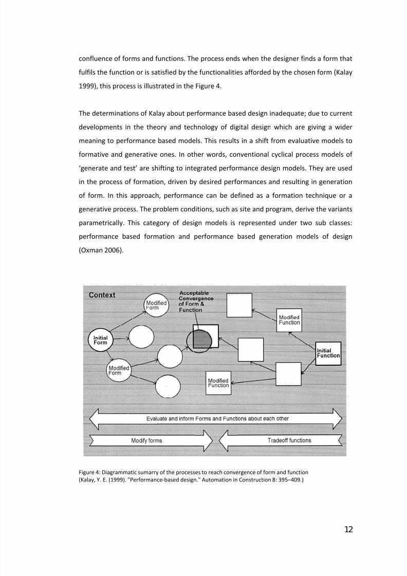
confluence of forms and functions. The process ends when the designer finds a form that
fulfils the function or is satisfied by the functionalities afforded by the chosen form (Kalay
1999), this process is illustrated in the Figure 4.
The determinations of Kalay about performance based design inadequate; due to current
developments in the theory and technology of digital design which are giving a wider
meaning to performance based models. This results in a shift from evaluative models to
formative and generative ones. In other words, conventional cyclical process models of
‘generate and test’ are shifting to integrated performance design models. They are used
in the process of formation, driven by desired performances and resulting in generation
of form. In this approach, performance can be defined as a formation technique or a
generative process. The problem conditions, such as site and program, derive the variants
parametrically. This category of design models is represented under two sub classes:
performance based formation and performance based generation models of design
(Oxman 2006).
Figure 4: Diagrammatic sumarry of the processes to reach convergence of form and function
(Kalay, Y. E. (1999). "Performance‐based design." Automation in Construction 8: 395–409.)
7/29/2019 AMSTERDAM SAVUNMA HATTININ DÖNÜŞTÜRÜLMESİNDE KILAVUZ OLARAK EDİMSEL MİMARLIK
http://slidepdf.com/reader/full/amsterdam-savunma-hattinin-doenuestueruelmesinde-kilavuz-olarak-edimsel 27/121
13
2.4.1 Performance based formation models
Performance‐based formation design can be regarded when digital simulations of external forces are applied in driving a formation process. Design performance may include among the following parameters: environmental performance, financial
cost, spatial,
social,
cultural,
ecological
and
technological
perspectives.
Performance‐based design employs analytical simulation techniques that produce
detailed parametric expressions of performance. These in turn can produce
formation responses to complex classes of performance requirements. (Oxman,2006)
The design of the City Hall London building demonstrates this approach.
2.4.1.1 City Hall, (1998‐2002), London, UK, Foster and Partners
City Hall consists of the headquarters of the Greater London Authority, which comprises
the Mayor of London and London Assembly. The main concept was to design a building
that expresses the transparency and accessibility of democratic process and
demonstrates the potential for a sustainable, virtually non‐polluting public building. The
main design approach was to generate the architectural form by environmental
performances with respect to light, heat, energy, movement and sound; so both the
design and design development are integrated in this project.
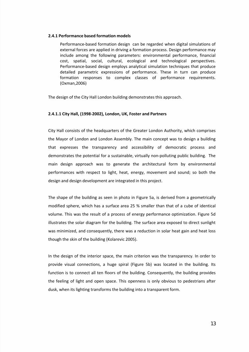
The shape of the building as seen in photo in Figure 5a, is derived from a geometrically
modified sphere, which has a surface area 25 % smaller than that of a cube of identical
volume. This was the result of a process of energy performance optimization. Figure 5d
illustrates the solar diagram for the building. The surface area exposed to direct sunlight
was minimized, and consequently, there was a reduction in solar heat gain and heat loss
though the skin of the building (Kolarevic 2005).
In the design of the interior space, the main criterion was the transparency. In order to
provide visual connections, a huge spiral (Figure 5b) was located in the building. Its
function is to connect all ten floors of the building. Consequently, the building provides
the feeling of light and open space. This openness is only obvious to pedestrians after
dusk, when its lighting transforms the building into a transparent form.

7/29/2019 AMSTERDAM SAVUNMA HATTININ DÖNÜŞTÜRÜLMESİNDE KILAVUZ OLARAK EDİMSEL MİMARLIK
http://slidepdf.com/reader/full/amsterdam-savunma-hattinin-doenuestueruelmesinde-kilavuz-olarak-edimsel 28/121
14
Acoustics also played a role in the final form of the structure. While designing the outer
form, architects noticed that its shape resulted in some acoustic problems. The initial
scheme for the assembly hall, which had a very smooth profile, was excessively
reverberant. Arup
developed
a process
for
visualizing
the
reflection
and
absorption
of
sound by surfaces (Figure 5e). After several iterations, a solution emerged which was
considered both architecturally and acoustically acceptable (Kolarevic 2005).
Figure 5: City Hall London
a‐ photo of the building, geometrically modified form of the building along its historic context of London
b‐ spiral stair cases located in the building c‐ photo of outdoor theatre located at the sunken ground floor (http://www.greatbuildings.com/buildings/London_City_Hall.html Last accessed 10 January 2011) d‐ the solar diagram for the building Kolarevic, B. (2005). Towards the Performative in Architecture. Performative Architecture Beyond Instrumentality. B. Kolarevic and A. M. Malkawi, Spon Press: 203‐213) e‐ the acoustical analysis of the debating chamber in the City Hall by Arup (Kolarevic, B. (2005). Computing the Performative. Performative Architecture Beyond Instrumentality. B. Kolarevic and A. M. Malkawi, Spon
Press: 193‐202.)
The form
of
this
building
is
not
only
designed
according
to
the
thermal
and
acoustic
simulations of the inside space of the building but also the wind. The wind directions
formed in its surroundings are also taken into consideration. Pedestrian comfort at the
1,000‐seat outdoor theatre (Figure 5c), located at the sunken ground floor, is another
important criterion. The effect of the building form on wind directions was simulated by
computational fluid dynamics. The building is designed in such a way that it would not
direct wind to this open air amphitheatre (Kolarevic 2005).

7/29/2019 AMSTERDAM SAVUNMA HATTININ DÖNÜŞTÜRÜLMESİNDE KILAVUZ OLARAK EDİMSEL MİMARLIK
http://slidepdf.com/reader/full/amsterdam-savunma-hattinin-doenuestueruelmesinde-kilavuz-olarak-edimsel 29/121
15
The building is designed so that its mechanical systems consume fifty percent less energy
than a typical air‐conditioned office building. The final form of the building derived from
multi criteria performance evaluation came under heavy criticism, because at first glance,
no one
would
believe
it
is
a public
service
building.
This
unusual,
bulbous
shape,
intended
to reduce surface area and improve energy efficiency, has been likened to many things,
such as Darth Vader's helmet, a misshapen egg, a woodlouse or a helmet for a
motorcyclist or for a futuristic gladiator.
2.4.2 Performance based generation models
Performance‐based generative design is based on generative processes driven by
performance
and
potentially
integrated
with
formation
processes.
This
develops
in
the direction of the ultimate condition of integrated enabling digital design media. Forces in a given context are fundamental to form‐making in digital design. External forces may be considered as environmental forces including structural loads, acoustics, transportation, site, program etc. Information itself is also considered as an external ‘force’ that can manipulate and activate responsive digital design
processes that are transparent to the designer. (Oxman,2006)
In a performance‐based generation model, data of performance simulations drive
generation and/or formation processes in order to generate the form. The designer can
interact with
representation,
generation
and
performance,
by
defining
the
performance,
generation criteria and interacting directly with the digital representation.
Digital design concepts that are associated with performance based generation can be
found in Lynn’s Port Authority Gateway, through animation techniques he used for
building form generation.
2.4.2.1
Port
Authority
Gateway
(1995),
New
York,
U.S.A.,
Greg
Lynn
This was a competition project which involved the design of a protective roof and a
lighting scheme for the underside of the bus ramps leading into the Port Authority Bus
Terminal, in New York. Greg Lynn used animation software, a medium for finding shape
rather than for representation alone. “Animate design”, which is a name given by the
designer of this process, is defined by motion. Forces are the effects on motion, affecting
consequently the form (Greg 1999).

7/29/2019 AMSTERDAM SAVUNMA HATTININ DÖNÜŞTÜRÜLMESİNDE KILAVUZ OLARAK EDİMSEL MİMARLIK
http://slidepdf.com/reader/full/amsterdam-savunma-hattinin-doenuestueruelmesinde-kilavuz-olarak-edimsel 30/121
16
Figure 6: Port Authority Gateway a‐ particle study of the Ninth Avenue motion forces b‐ view of Lincoln Tunnel approach particle study c‐ view of phase portraits as curvilinear vectors d‐ view of tensile surfaces e‐ view of structural vectors and tensile surfaces (Greg, L. (1999). Animate Form, Princeton Architectural Press.)
The site was modelled using forces that simulate the movement and flow of pedestrians,
cars, and buses across the site. Each of them had differing speeds and intensities of
movement along
the
Avenue,
streets,
and
four
elevated
bus
ramps
emerging
from
below
the river. These various forces of movement are defined by forces, establishing a gradient
field of attraction across the site. To define a form from these forces, Lynn introduced
geometric particles that change their position and shape according to the influence of
these forces. These particle studies, which are shown in Figure6a and Figure 6b, are done
by using animation techniques. Consequently a series of phase portraits of the cycles of
movement over a period of time were captured. These phase portraits are swept with a
secondary structure
of
tubular
frames
linking
the
ramps,
existing
buildings
and
the
Port
Authority Bus Terminal (Greg 1999). The view of phase portraits as curvilinear vectors is
illustrated in Figure 6c. Eleven tensile surfaces are stretched across these tubes as an
enclosure and projection surface as shown in Figure 6d and e.

7/29/2019 AMSTERDAM SAVUNMA HATTININ DÖNÜŞTÜRÜLMESİNDE KILAVUZ OLARAK EDİMSEL MİMARLIK
http://slidepdf.com/reader/full/amsterdam-savunma-hattinin-doenuestueruelmesinde-kilavuz-olarak-edimsel 31/121
17
CHAPTER 3
PERFORMATIVE DESIGN
Performance is one of the most used, even sometimes misused and abused words in
architecture. The ways in which performance is understood in architecture are often
contradictory and the meanings associated with it are often articulated as opposites
(Kolarevic 2005). The descriptions of performative architecture are also numerous. Its
paradigmatic appeal lies precisely in the multiplicity of meanings associated with the
performative in
architecture;
however,
performance
is
still
one
of
least
defined
concepts
in architecture. Recent developments in technology, cultural theory and sustainability
increased the interest in performance as a design paradigm (Kolarevic 2005). In this
expansive span the definitions of performative architecture can be grouped under two
categories. The first group is the one which has a narrow point of view towards
performative architecture and sees performative architecture as a technical development
in digital design and manufacturing processes. This approach sees performative
architecture as
a technical
(structural,
thermal,
acoustical,
etc.)
issue.
Second
group
searches for the theory and meaning of performative architecture and their definitions
spans multiple realms (financial, spatial, social, cultural, etc.).
Both approaches are operative in many levels beyond just the aesthetic and utilitarian.
Determining different performative aspects in a particular project and reconciling
conflicting performance goals in a creative and effective way are a key challenge in
performative architecture.
3.1 Performative Design as Technical Development
Recent technologies in design enable more complex design models, resulting in transition
to a new model of performance based design, which is defined as performative design.
The first step of performative architecture is to combine performance ideas with the
design from the conceptual stage. Consequently, performative ideas are a shaping and

7/29/2019 AMSTERDAM SAVUNMA HATTININ DÖNÜŞTÜRÜLMESİNDE KILAVUZ OLARAK EDİMSEL MİMARLIK
http://slidepdf.com/reader/full/amsterdam-savunma-hattinin-doenuestueruelmesinde-kilavuz-olarak-edimsel 32/121
18
generative factor rather than just being an evaluation criterion. In performative
architecture, the digital model should have a special logic, in which performance and
form generation must be synchronized. This way, the model can act as a mechanism to
generate and
modify
designs,
which
also
requires
closer
integration
between
evaluation
and design. It is based on a formation process driven by analytical techniques that can
directly modify the geometric model. Performative models create a seamless and
integrated process of performance based design (Oxman 2009).
3.1.1 Morpho‐Ecological Approach for Design
Achim Menges and Michael Hensel’s ‘Morpho‐Ecological’ approach to design is an
example for performative architecture. Their approach is from a technical aspect focuses
on environmental issues in the generation process; however, their definition has a wider
perspective. Hensel and Menges also include utilization and creation of emergent effects
and innovative spatial arrangements in their analysis process, which takes place after the
generation of design alternatives. Their approach is an alternative understanding of
performance. It is an understanding of multi‐parameter effectiveness rather than single
parameter optimization. This is an approach where the start of the design includes both
the logics
of
how
material
constructions
are
made
and
the
way
they
will
interact
with
environmental conditions and stimuli. This sort of understanding of performative
architecture uses computation in a key role in analytical and generative modes and in
combination with computer‐controlled manufacturing processes. It is the integration of
materialisation, production and construction which provides a higher level of design
synthesis. It uses computational design and manufacturing technologies to support the
evaluation of performative effects. It is the design of morphological complexity and
performative
capacity
without
differentiating
between
form‐
generation
and
materialisation processes (Menges and Hensel 2008).
Morpho Ecological approach uses multicriteria performance in a wider span rather than
being simple efficiency models. The compound models used in this approach enables the
emergence of unanticipated design solutions, which results in the ensuing potential for
different modes of habitation. Effectiveness in this design approach is the ability to

7/29/2019 AMSTERDAM SAVUNMA HATTININ DÖNÜŞTÜRÜLMESİNDE KILAVUZ OLARAK EDİMSEL MİMARLIK
http://slidepdf.com/reader/full/amsterdam-savunma-hattinin-doenuestueruelmesinde-kilavuz-olarak-edimsel 33/121
19
generate emergent effects which requires creativity, intelligence and instrumentality in
devising integral analytical methods.
3.2 Performative
Design
as
a shift
of
orientation
in
architecture
Is there any sustained discussion of the social dimension of architecture, beyond
general references to a shiny bendy new world or the change in construction
methods that CAM/CAD may bring about? What about global warming and global urbanisation? Engaging with global warming and global urbanisation requires a willingness to understand and work with the materiality of the built environment, to complete the loop from built space to cyberspace to built space, not simply in
terms of getting one’s digital confection built but in terms of building in ways that are materially responsive to material conditions. (Hagan, 2008)
These words of S. Hagan are an inquiry into a deeper meaning of instruments and
methods in architecture. This should not be interpreted as a dedication of performative
architecture to a technical interpretation. It is a new understanding of the way buildings
are imagined, made and experienced. But this understanding will not result from the
development and deployment of new techniques and instruments alone. It is also related
with the meanings of these technologies. In this approach, performative architecture is
the marriage of virtual reality capable of accurately simulating physical experience, and
physical reality capable of a total incorporation of cyberspace (Hagan 2008). In
performative architecture the building gives a more difficult message. Rather than look at
me, the building requests the understanding of the way it works and why.
To understand the message of performative architecture, an understanding of the
marriage of binary oppositions in avant‐garde architecture is needed. In the current era,
there are several binary oppositions, such as body‐ mind, nature‐ culture, digital‐
material, urban
space
‐cyberspace,
virtual
space
‐real
space.
These
binary
opposites
are
dependent on each other rather than standing alone; in addition they do not have any
superiority on each other. They are complementary and the reason for the existence of
the other. In architecture, the fusion of binary opposites, such as matter and intelligence,
is required, and this can be achieved only with developing material technology.
Responding to user needs and maximising the conservation of energy is just the
beginning. In computational architecture, cyberspace is used to see the incalculable. It

7/29/2019 AMSTERDAM SAVUNMA HATTININ DÖNÜŞTÜRÜLMESİNDE KILAVUZ OLARAK EDİMSEL MİMARLIK
http://slidepdf.com/reader/full/amsterdam-savunma-hattinin-doenuestueruelmesinde-kilavuz-olarak-edimsel 34/121
20
consists of sophisticated tools for analysis of the forces of the real world. As
computational models embody more information, the more nature‐like they will become.
The developing technologies of CAD/CAM strengthen the relation between material and
digital.
Performative architecture also widens new territories of architecture, such as responding,
moving and evolving. Even some visual dynamism can be seen in non‐orthogonal forms.
In addition, CAD/CAM technologies enable the production of non‐ linear forms, costing
more or less the same as orthogonal ones; however, the dynamism of digital architecture
should go beyond this. The building should be designed in such a way that it could
interact with site, people, climate and time, and change according to this interaction
(Hagan 2008). Therefore, the general outline of performative architecture can be defined
as the shift of orientation in architectural theory and practice from what the building is to
what it does, defining the first by means of the second. Accordingly the new territories of
architecture that unfold with performative architecture are going to categorized under
three headings such as: performance as controlling the unbuilt, architecture as
performance and movement as performance.
3.2.1 Performance
as
controlling
the
unbuilt
No doubt the building is a technical and aesthetic work, but it is known as such
through its workings. The building is its effects and is known mainly through them, through its actions or performances. What is true for people is also true for buildings – character shows itself in what they do. (Leatherbarrow, 2005).
Performative architecture suggests a different kind of understanding of building. It is not
a technical preparation, nor a representation of such preparation. It is both a non‐
technical and non‐aesthetic performance. It is the intelligence of designer of which
acknowledges a continuous need for readjustments in order to reclaim its own
equilibrium and sustain its engagement with unbuilt or previously built eventualities
(Leatherbarrow 2005).
During the design stage of a building, unforeseen aspects should be transformed into the
foreseen. For instance, one can answer to how the designed object acts with ambient
7/29/2019 AMSTERDAM SAVUNMA HATTININ DÖNÜŞTÜRÜLMESİNDE KILAVUZ OLARAK EDİMSEL MİMARLIK
http://slidepdf.com/reader/full/amsterdam-savunma-hattinin-doenuestueruelmesinde-kilavuz-olarak-edimsel 35/121
21
conditions (gravity, wind, sunlight…) or to how it works with and against site (forces of
the site). The term bad building is used for the ones which can not respond to unexpected
conditions. So, the first step of performative architecture is the capacity to respond to
both the
foreseen
and
the
unforeseen.
Leather
Barrow
names
works
of
Jean
Nouvel
as
“engagement between what was and what was not constructed and the building’s
willingness or need to interact with what is not.” (Leatherbarrow 2005). The design of
Louvre Museum for Abu Dhabi is an example for such an understanding.
3.2.1.1 Louvre Museum, (2007‐2012), Abu Dhabi, United Arab Emirates, Jean Nouvel
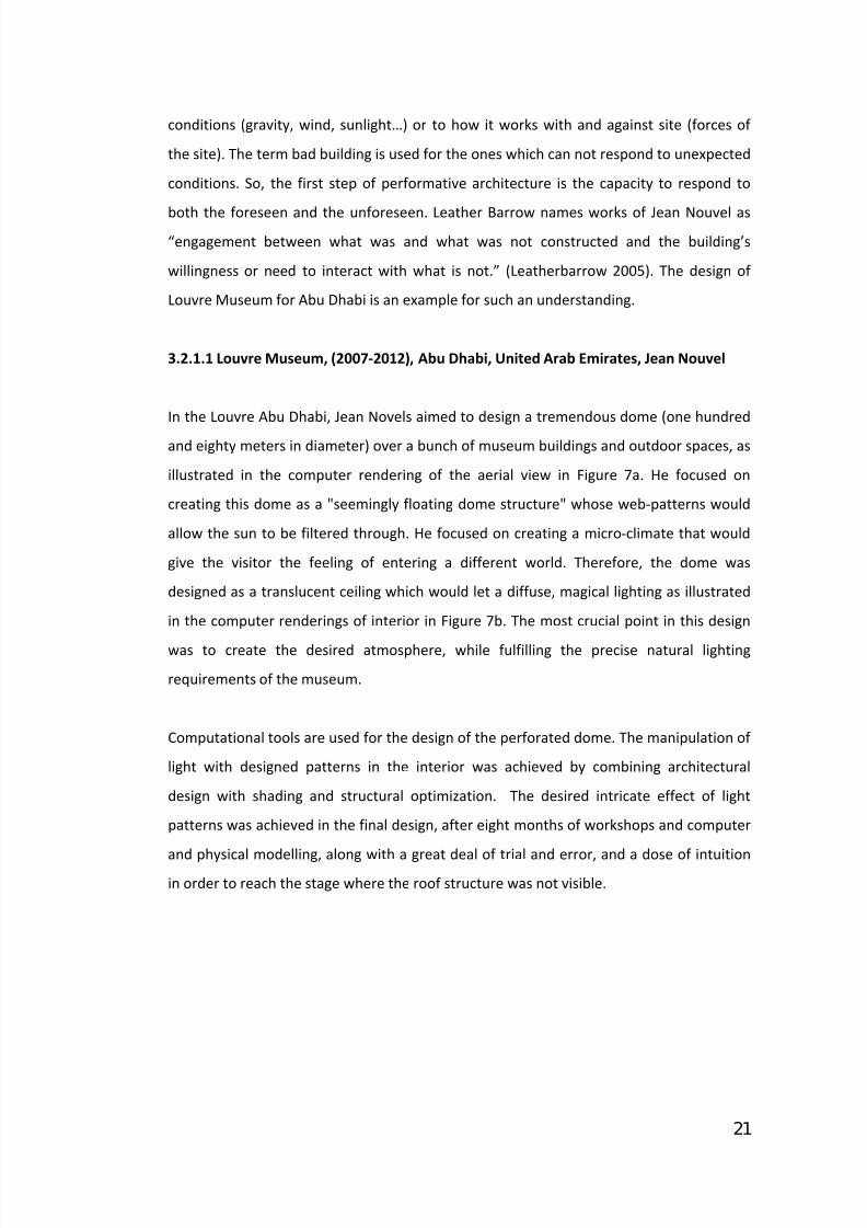
In the Louvre Abu Dhabi, Jean Novels aimed to design a tremendous dome (one hundred
and eighty meters in diameter) over a bunch of museum buildings and outdoor spaces, as
illustrated in the computer rendering of the aerial view in Figure 7a. He focused on
creating this dome as a "seemingly floating dome structure" whose web‐patterns would
allow the sun to be filtered through. He focused on creating a micro‐climate that would
give the visitor the feeling of entering a different world. Therefore, the dome was
designed as a translucent ceiling which would let a diffuse, magical lighting as illustrated
in the computer renderings of interior in Figure 7b. The most crucial point in this design
was to
create
the
desired
atmosphere,
while
fulfilling
the
precise
natural
lighting
requirements of the museum.
Computational tools are used for the design of the perforated dome. The manipulation of
light with designed patterns in the interior was achieved by combining architectural
design with shading and structural optimization. The desired intricate effect of light
patterns was achieved in the final design, after eight months of workshops and computer
and
physical
modelling,
along
with
a
great
deal
of
trial
and
error,
and
a
dose
of
intuition
in order to reach the stage where the roof structure was not visible.

7/29/2019 AMSTERDAM SAVUNMA HATTININ DÖNÜŞTÜRÜLMESİNDE KILAVUZ OLARAK EDİMSEL MİMARLIK
http://slidepdf.com/reader/full/amsterdam-savunma-hattinin-doenuestueruelmesinde-kilavuz-olarak-edimsel 36/121
22
Figure 7: Louvre Museum Abu Dhabi a‐ computer rendering of the aerial view
b‐ computer rendering of the interior (http://www.dezeen.com/2007/05/07/jean‐nouvel‐in‐abu‐dhabi/ Last accessed 10 January 2011) c‐ a snapshot from the computer program that is developed by Buro Happold’s Smart Solutions Team
d‐ 1/200 scale physical model (Al Fisher and Buro Happold’s presentation: The Louvre http://www.metudelft.net/comparch/video%20sgop.html Last accessed 10 January 2011) e‐Sheikh Sultan and Jean Nouvel under the 1/1 scale prototype (http://www.e‐architect.co.uk/dubai/louvre_abu_dhabi.htm Last accessed 10 January 2011)
Buro Happold’s Smart Solutions Team developed a computer modelling program to
design a structural form that optimised the roof’s structural efficiency a snapshot from
the program is shown in Figure 7c. The initial generation of the structural geometry is
based on a unit. After much iteration, the design of the dome was achieved so it would fit
the structural requirements, which also provided the differentiated and desired lighting
conditions for different spaces. The web patterns in the dome were designed so that
translucency amounts were differentiated for different functions, such as museum
galleries, corridor spaces or outdoor spaces.
A number of physical models of the dome were created from 1/200 scale (Figure 7d) to
1/1 scale. The real scale prototype is a 6m x 6m replica of a section of the roof, which has
been built close to the site and used to verify the roof pattern and complex light paths.
This huge model has enabled the design team to assess the effects of different layers of

7/29/2019 AMSTERDAM SAVUNMA HATTININ DÖNÜŞTÜRÜLMESİNDE KILAVUZ OLARAK EDİMSEL MİMARLIK
http://slidepdf.com/reader/full/amsterdam-savunma-hattinin-doenuestueruelmesinde-kilavuz-olarak-edimsel 37/121
23
cladding and track the shafts of light as the sun moves. Figure 7e illustrates Sheikh Sultan
and Jean Nouvel this 1/1 scale prototype.
Jean Novel
claims
to
put
nature
to
work
in
his
architecture.
The
beauty
and
richness
of
the surfaces of his work do not result from the design or construction technique alone,
but also from ambient lighting. Jean Novel sees the environment as internal to his
buildings.
3.2.2 Architecture as performance
Another point of view in performative architecture is thinking of architectural
performance as an art performance; like what might be seen on theatrical stage instead
of accepting it as the performance of a car engine. However, if compared to dance and
music, the building seems inert and inactive, and when compared to film architecture, it
seems positively motionless. So what does the architectural work do as performance?
The house, theatre and museum just sit where they have been built. They wait for a
visitor’s arrival and experience as if they could only be enlivened by a visitor’s existence.
But is
the
building
only
what
we
make
of
it?
There
is
something
more
to
it.
If
it
was
only
the consequence of an inhabitant’s intentions, it would be impossible to understand why
buildings depress and delight us.
To understand architectural performance, an analogy to musical or theatrical
improvisation can be useful. The stops and positions of a building’s elements describe the
guidelines of a performance; they enable spontaneous qualifications that adapt the
ensemble
to
particular
conditions
as
they
vary
over
time.
Then,
building
performance
comes alive with architectural drama. So, it can be concluded that first step of
architectural performance is to outline strategies of adjustment (Leatherbarrow 2005).
The urban sculpture in Doetinchem named D‐Tower and the skin of the museum building
Kunsthaus Graz can be literally seen as architectural performance pieces.

7/29/2019 AMSTERDAM SAVUNMA HATTININ DÖNÜŞTÜRÜLMESİNDE KILAVUZ OLARAK EDİMSEL MİMARLIK
http://slidepdf.com/reader/full/amsterdam-savunma-hattinin-doenuestueruelmesinde-kilavuz-olarak-edimsel 38/121
24
3.2.2.1 D‐Tower, (1998–2003), Doetinchem, the Netherlands, NOX/ Lars Spuybroek
The D‐tower consists of three parts: a website which is accessible to anyone; a
questionnaire accessible
to
a hundred
different
people
that
have
a special
password
each
year, and a tower. The tower is a 12 meter high structure standing on 4 columns as shown
in the photo in Figure 8a. The complex surface was made of epoxy panels (Figure 8b)
which are shaped by a computer generated moulding technique (CNC milled styrofoam).
The tower changes its colour (Figure 8c) according to the emotional state of the city’s
residents which is computed from the responses of the city’s habitants to the
questionnaire. Daily emotions such as hate, love, happiness and fear are mapped into
four colours; green, red, blue and yellow. By looking at the tower, one can see the
dominant emotion of the city. The tower also acts as a capsule in which the city
inhabitants could leave love letters, flowers, etc. This is a project where the intensive
(feelings, qualia) and the extensive (space, quantities) exchange roles, where human
action, colour, money, value and feelings all become networked entities (Kolarevic 2005).
Figure 8: D‐Tower a‐ photo of the tower b‐ complex surface of the tower made of epoxy panels c‐ color changes of the tower (Kolarevic, B. (2005). Towards the Performative in Architecture. Performative Architecture Beyond
Instrumentality. B. Kolarevic and A. M. Malkawi, Spon Press: 203‐213.)
7/29/2019 AMSTERDAM SAVUNMA HATTININ DÖNÜŞTÜRÜLMESİNDE KILAVUZ OLARAK EDİMSEL MİMARLIK
http://slidepdf.com/reader/full/amsterdam-savunma-hattinin-doenuestueruelmesinde-kilavuz-olarak-edimsel 39/121
25
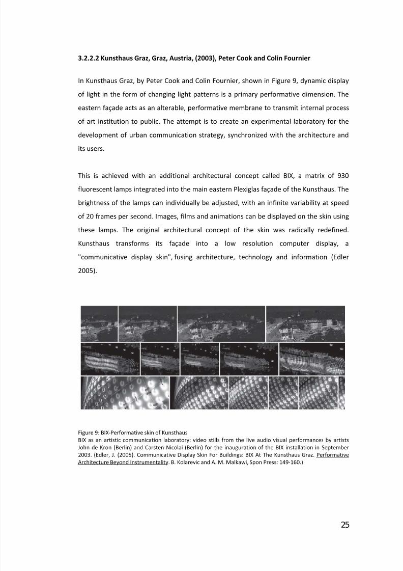
3.2.2.2 Kunsthaus Graz, Graz, Austria, (2003), Peter Cook and Colin Fournier
In Kunsthaus Graz, by Peter Cook and Colin Fournier, shown in Figure 9, dynamic display
of light in the form of changing light patterns is a primary performative dimension. The
eastern façade acts as an alterable, performative membrane to transmit internal process
of art institution to public. The attempt is to create an experimental laboratory for the
development of urban communication strategy, synchronized with the architecture and
its users.
This is achieved with an additional architectural concept called BIX, a matrix of 930
fluorescent lamps integrated into the main eastern Plexiglas façade of the Kunsthaus. The
brightness of
the
lamps
can
individually
be
adjusted,
with
an
infinite
variability
at
speed
of 20 frames per second. Images, films and animations can be displayed on the skin using
these lamps. The original architectural concept of the skin was radically redefined.
Kunsthaus transforms its façade into a low resolution computer display, a
"communicative display skin", fusing architecture, technology and information (Edler
2005).
Figure 9: BIX‐Performative skin of Kunsthaus BIX as an artistic communication laboratory: video stills from the live audio visual performances by artists John de Kron (Berlin) and Carsten Nicolai (Berlin) for the inauguration of the BIX installation in September 2003. (Edler, J. (2005). Communicative Display Skin For Buildings: BIX At The Kunsthaus Graz. Performative Architecture Beyond Instrumentality. B. Kolarevic and A. M. Malkawi, Spon Press: 149‐160.)
7/29/2019 AMSTERDAM SAVUNMA HATTININ DÖNÜŞTÜRÜLMESİNDE KILAVUZ OLARAK EDİMSEL MİMARLIK
http://slidepdf.com/reader/full/amsterdam-savunma-hattinin-doenuestueruelmesinde-kilavuz-olarak-edimsel 40/121
26
3.2.3 Movement as Performance
It is often the movement of people around and through a building that gives architecture
its performative
capacity.
It
is
the
experience
of
the
building’s
materiality
and
spatial
presence. In some recent projects, performativity is in the kinetic effects of the
architecture. Rather than the subject that moves, the object itself creates an architecture
of spectacle and architecture of performance.
Because of the acceleration caused by the advent of computers, these concepts are no
longer just a dream. Due to developing digital technologies, the simulation capacities of
cyberspace are increasing. In the future, virtual reality will be capable of exactly
simulating physical experience, and physical reality will be capable of a total
incorporation of cyberspace. This will result in a future we can only imagine now:
architecture and cities that swell and shrink, extend and circle, in direct response to what
is going on in the collective mind of cyberspace.
Exploration of new formal territories preoccupies the works of contemporary digital
avant‐garde on its surface; the building skin or building unit, and not usually in the
structure. On the other hand, works of the Tristan d'Estree Sterk’s office explore kinetic
and responsive
structure.
3.2.3.1 Filamentosa: Ultra‐Lightweight Skyscraper, (2004‐now), Chicago Illinois, U.S.A.,
Orambra
Filamentosa: the Ultra‐Lightweight Skyscraper in Chicago Illinois, U.S.A. (2004‐now) by
Orambra (Office for Robotic Architectural Media& Bureau for Responsive Architecture) is
a
new
type
of
ultra‐
lightweight
skyscraper.
In
Figure
10a
collage
of
the
Chicago
silhouette
with computer rendering of the Filamentosa is shown. It is a skyscraper that is responsive
to nature. Its structural frame and living skin adapt to reduce the amount of material and
energy required to live within, construct and maintain.

7/29/2019 AMSTERDAM SAVUNMA HATTININ DÖNÜŞTÜRÜLMESİNDE KILAVUZ OLARAK EDİMSEL MİMARLIK
http://slidepdf.com/reader/full/amsterdam-savunma-hattinin-doenuestueruelmesinde-kilavuz-olarak-edimsel 41/121
27
Figure 10: Filamentosa a‐ collage of the Chicago silhouette with computer rendering of the Filamentosa b‐ computer renderings of the Filamentosa illustrating smart systems and building frame c‐ prototype of the adaptable structure d‐ Tristan d'Estree Sterk working with the physical prototype e‐different components of the physical prototype (http://www.orambra.com/ Last accessed 10 January 2011)
Tristan d'Estree Sterk started the design with the objective of creating a building which
was taller,
lighter
and,
more
importantly,
more
sustainable
and
cheaper.
For
this
reason,
he desired more for his building than being a series of smart systems attached to a dumb
building frame (Figure 10b). He designed an intelligent building with the ability of
readjusting itself to changing stimuli. For instance, in extreme cases such as storm and
earthquake, the building could readjust its structural balance. In addition, it could even
adjust its shape to improve shading in summer or day lighting in winter.
Tristan d'Estree Sterk ended up designing a skyscraper consisting of intelligent frames,
skins and systems. He designed a generative system with defined structural relationships,
which had the ability to evolve according to changing environmental conditions; Figure
10c illustrates the adaptable structural system that responds to environment.
In his prototype, he managed to build a stable structural system, consisting of struts and
cables of adjustable tension. He used sensors to detect displacement due to an uneven
distribution of forces in a case of external loadings of various causes, such as wind, storm

7/29/2019 AMSTERDAM SAVUNMA HATTININ DÖNÜŞTÜRÜLMESİNDE KILAVUZ OLARAK EDİMSEL MİMARLIK
http://slidepdf.com/reader/full/amsterdam-savunma-hattinin-doenuestueruelmesinde-kilavuz-olarak-edimsel 42/121
28
and earthquake. These sensors send this information to a centralized computer which can
adjust the tension in the cables and turn the model into upright position. Therefore, the
building can stand up by itself (Orambra 2010). Figure 10d shows Tristan d'Estree Sterk
working with
the
physical
prototype
composed
of
the
sensors,
centralized
computer
and
the adaptable structure and Figure 10e shows these different components of the physical
prototype.
In nature, it is possible to observe many examples of flexible structure, such as the
behaviour of trees bending and responding to the wind to prevent breaking. If buildings
are designed to have more flexibility, the damage due to natural disasters, such as
hurricanes and earthquakes could be lowered. The prototype of Sterk proves that this can
be achievable in the near future; besides he manages to build this system with using less
material than the conventional skyscrapers.
3.3 Definition of performative architecture
After reviewing the papers and the example buildings, it can be concluded that
performative architecture consists of a new model of performance based design with a
wider span
of
realms.
Therefore,
it
is
necessary
to
define
of
performative
architecture
and performance criteria that are used below.
Performative architecture is the shift of orientation in architectural theory and practice
from what the building is to what it does. It defines the architectural object, not by how it
appears, but rather by its capability of affecting, transforming and doing; in other words,
by how it performs.
The understanding of how a building performs is a more difficult message than merely
aesthetic messages. Therefore, instead of appealing to the aesthetics, the buildings
request the understanding of their functionality and its reason. (How do the buildings
work? For which reason?) They can be: structural, environmental, economic, ecological,
spatial, and technological. The aim of performative architecture is to prevent clashing
ideas between these reasons by optimization methods.

7/29/2019 AMSTERDAM SAVUNMA HATTININ DÖNÜŞTÜRÜLMESİNDE KILAVUZ OLARAK EDİMSEL MİMARLIK
http://slidepdf.com/reader/full/amsterdam-savunma-hattinin-doenuestueruelmesinde-kilavuz-olarak-edimsel 43/121
29
Optimization should not be limited to a technical interpretation. If performative
architecture is limited to simulation and evaluation, then there will not be any difference
between performative architecture and engineering. Performative architecture should
have the
capability
to
generate.
It uses digital generation and modification to search for alternatives for a design. The
generated emergent effects of the architecture (on nature, site, people, climate and time)
are being analyzed both qualitatively and quantitatively in performative architecture. As a
paradigm for architecture, performance describes the processes through which culture,
technology and architecture become interrelated to form a complex field of relations
which produce new and powerful effects. Instead of describing the architectural object,
performative architecture focuses on how the architectural object performs by producing
new effects that transform culture; therefore, the qualitative analysis of the alternatives
should also be done taking into account the ability to produce powerful effects.

7/29/2019 AMSTERDAM SAVUNMA HATTININ DÖNÜŞTÜRÜLMESİNDE KILAVUZ OLARAK EDİMSEL MİMARLIK
http://slidepdf.com/reader/full/amsterdam-savunma-hattinin-doenuestueruelmesinde-kilavuz-olarak-edimsel 44/121
30
CHAPTER 4
PERFORMANCE ASSESSMENT
Performative architecture is defined in the previous Chapter as an approach which
consists of search for alternatives, quantitative and qualitative analysis, and emergent
effects. Such a design model with generative capabilities enables generation of large
number of instances. Taxonomy of these instances is needed for control, categorization
and selection of a large set of generated instances. In performative architecture, a
categorization and
selection
depending
on
performance
is
an
obvious
criterion
for
taxonomy of generated instances.
The study for constituting taxonomy of building performance criteria is done in four
steps. After defining performative architecture, taxonomy of performance criteria is
needed for further research in performative architecture. After defining performative
architecture, a taxonomy of performance criteria is needed for further research in
performative architecture.
This
study
is
done
in
four
steps.
First
step
is
literature
search
related with the categorizations of basic building performance evaluation levels. Second
step is to combine the literature search with case study examples by reviewing the
projects that are related with digital models according to building performance
assessment levels. As a conclusion of these two studies a categorization of architectural
performances can be structured. The final step is the inquiry of the computational tools
related with performance.
4.1 Building performance evaluation levels
Building performance assessment is multidisciplinary and it has generated applied
research that lacked a coherent theoretical framework until recently. Three categories of
criteria for building performance were defined centuries ago by Roman Architect
Vitruvius. These were firmness, commodity and delight. This historic approach to setting
priorities on building performance has been transformed into three levels of priority.

7/29/2019 AMSTERDAM SAVUNMA HATTININ DÖNÜŞTÜRÜLMESİNDE KILAVUZ OLARAK EDİMSEL MİMARLIK
http://slidepdf.com/reader/full/amsterdam-savunma-hattinin-doenuestueruelmesinde-kilavuz-olarak-edimsel 45/121
31
They are listed below:
1‐health, safety and security performance
2‐functional, efficiency performance
3‐psychological,
social,
cultural
and
aesthetic
performance
(Preiser
and
Vischer
2005).
Level 1 pertains to building codes and life safety standards projects must comply with.
Level 2 refers to the state of the art knowledge about building types and systems. Level 3
pertains to research based design guidelines, which are less codified, but nevertheless
equally important for designers.
Each category of objectives includes sub‐goals. At the first level, one sub‐goal might be
safety; at the second level, sub‐goals can be functionality, affective and efficient work
process, adequate space, and the adjacencies of functionality related areas; and at the
third level, sub‐goals include privacy, sensory stimulation and aesthetic appeal. For a
number of sub‐goals, performance levels interact. They may also conflict with each other,
requiring resolution in order to be effective.
This framework relates elements of buildings and settings to building users and their
needs and
expectations.
While
applying
this
approach,
the
physical
environment
is
considered as more than just a building or shell because of the focus on settings and
spaces for particular activities. Performance variables can be seen in terms of ascending
hierarchies from small to large scale or from lower to higher levels of abstraction. For
each setting and user group, performance levels for sensory environments and specific
quality performance criteria need to be established, for example, the acoustic, luminous,
olfactory, visual, tactile, thermal and gravitational criteria (Preiser and Vischer 2005).
In summary, these levels of building performance create the basic framework which is
commonly accepted and used in Building Performance Evaluation (BPE). BPE
systematically relates buildings and settings to users and their environmental needs
(Preiser and Vischer 2005).
Besides these three, there are also differences between the quantitative and qualitative
aspects of building performance and their respective performance measures. Many
7/29/2019 AMSTERDAM SAVUNMA HATTININ DÖNÜŞTÜRÜLMESİNDE KILAVUZ OLARAK EDİMSEL MİMARLIK
http://slidepdf.com/reader/full/amsterdam-savunma-hattinin-doenuestueruelmesinde-kilavuz-olarak-edimsel 46/121
32
aspects of building performance are quantifiable, such as lighting, acoustics, temperature,
humidity, durability of materials, amount and distribution of square footage etc.
Qualitative aspects of building performance pertain to ambiance of space; in other words:
the appeal
to
the
sensory
modes
of
touching,
hearing,
and
smelling,
kinaesthetic
and
visual perception, including colour. The qualitative aspects of the building, such as
aesthetic beauty or visual compatibility with a building’s surroundings, can be the subject
of consensus among the public. The recent research on computational aesthetics
indicate that the rules of aesthetics and beauty might also be formulated such that they
can be used in computational methods.
4.2 Review of projects that are related with digital models
Building performance evaluation levels are an engineering point of view; therefore, in
order to see its counterparts in design, the buildings discussed in the previous chapter are
reviewed according to BPE levels. The review is done for three stages of each building
such as: project goals, process to achieve the goals, and shortcomings. The performance
criteria for each stage are listed as below.
M.art.A. Museum
Project goals: aesthetic appeal, become a landmark as a tourist attraction like the Bilbao
museum;
Process to achieve the goals: aid from CAD to enable data flow between digital and
physical models;
Shortcomings: environmental, structural and economic optimization, the building is
expensive to construct and maintain.
Kunsthaus Graz
Project goals: urban communication;
Process to achieve the goals: transmit the internal process of the art institution to public,
structural optimization, prevent high costs.

7/29/2019 AMSTERDAM SAVUNMA HATTININ DÖNÜŞTÜRÜLMESİNDE KILAVUZ OLARAK EDİMSEL MİMARLIK
http://slidepdf.com/reader/full/amsterdam-savunma-hattinin-doenuestueruelmesinde-kilavuz-olarak-edimsel 47/121
33
Dynaform BMW Pavilion
Project goals: communicating the message of the BMW Company, launching BMW’s new
series;
Process to
achieve
the
goals:
virtual
forces
by
means
of
specific
parameters
of
the
site
(flows of site, adjacent buildings) and program, standardization of structure to achieve
structural optimization, mass customization.
City Hall
Project goals: to give social message of transparency and accessibility of democratic
process and to represent an image of a sustainable and non‐polluting city;
Process to achieve the goals: optimization of energy performance, optimization of the
form of the assembly hall to meet acoustic requirements, optimization of the form
according to wind patterns at the pedestrian level;
Shortcomings: mass customization, innovative aesthetic form.
Port Authority Gateway
Project goals: integration with site;
Process to achieve the goals: simulation of site flows such as pedestrian, car, or bus, to
establish a gradient
field
of
attraction
across
the
site.
Louvre Museum
Project goals: appearance, create desired atmosphere with light patterns;
Process to achieve the goals: simultaneous lighting simulations, structural and
architectural design.
D‐
Tower
Project goals: urban communication;
Process to achieve the goals: adjustable colour that can change according to the
emotions of the city.
Filamentosa: Ultra‐Lightweight Skyscraper
Project goals: adjustability according to changing environmental conditions, reduce the
amount of material and energy required to construct, live and maintain.

7/29/2019 AMSTERDAM SAVUNMA HATTININ DÖNÜŞTÜRÜLMESİNDE KILAVUZ OLARAK EDİMSEL MİMARLIK
http://slidepdf.com/reader/full/amsterdam-savunma-hattinin-doenuestueruelmesinde-kilavuz-olarak-edimsel 48/121
34
Process to achieve the goals: prototypes with an adjustable system which is composed of
struts, tension cables, sensors, and a computer.
4.3 Categorization
of
architectural
performances
As seen in above performance criteria for each building differ depending on many
reasons, such as functions, site and etc. Architectural performances can be divided into
three, as illustrated in Table 1, similarly to building performance assessment
categorization. However, the only difference is that architectural performances do not
flow the hierarchic structure of BPE levels. What causes architecture to be classified as
performative is the correct selection of performances and relationships. Either
environmental performances can clash with economic performances, or aesthetic ones
can clash with social ones. Defining the adequate geometrical relationships to prevent
these conflicts is the main categorization for performative architecture.
Table 1: categorization of architectural performances
4.4 Computational Tools Related with Performance
The wide range of digital tools is opening up new territories for conceptual, formal and
tectonic exploration, articulating an architectural morphology focussed on the emergent
and adaptive properties of form. The conventional design and drawing understandings
are shifting to digitally generated forms, which are calculated by chosen generative

7/29/2019 AMSTERDAM SAVUNMA HATTININ DÖNÜŞTÜRÜLMESİNDE KILAVUZ OLARAK EDİMSEL MİMARLIK
http://slidepdf.com/reader/full/amsterdam-savunma-hattinin-doenuestueruelmesinde-kilavuz-olarak-edimsel 49/121
35
computational method. Digital generative techniques bring the shift of emphasis from
making of form to the finding of form (Kolarevic 2003).
In generative
system
of
formal
production,
the
designer
controls
the
behaviour
over
time,
and selects forms that emerge from its operation. This time based modelling technique is
used as an invisible dynamic process that is shaping the physical context of architecture,
which is driven by socio‐economic and cultural forces. Greg Lynn uses these words: “the
context of design becomes active abstract space that directs form within a current of
forces that can be stored as information in shape of the form” (Greg 1999).
These generative techniques used for representation and formal appearance in avant‐
garde contemporary architecture should not be limited only to these issues. If in the
conceptualizing process the dynamic forces that affect architecture are visualized by also
introducing the dimension of time, then we can begin to qualify their effects. It also
opens the potentials to qualify them in certain technical aspects. There is a range of
digital analytical tools that can help designers to assess performance aspects to their
projects.
4.4.1 Analytical
The research in digital performance analysis and simulation tools dates back more than
three decades. Many of concepts and techniques were pioneered in late 1960’s. The first
use of computer graphics for building assessment was in 1966, and the first building
performance assessment package appeared in 1972. The 1970’s, the architects were
enabled to obtain highly accurate predictions of building performances. For instance:
heat
loss,
daylight
analysis,
shadow
predictions
and
acoustic
performance
(Cross
and
Maver 1973).
Algorithms were used to develop computational systems to assist designers in their
activities by providing either guidance through advice or optimization. The contribution of
knowledge based systems and complex problem solving methods has been significant in
initiating the use of computational techniques to solve performance based decision
making problems.

7/29/2019 AMSTERDAM SAVUNMA HATTININ DÖNÜŞTÜRÜLMESİNDE KILAVUZ OLARAK EDİMSEL MİMARLIK
http://slidepdf.com/reader/full/amsterdam-savunma-hattinin-doenuestueruelmesinde-kilavuz-olarak-edimsel 50/121
36
In early 1970’s, PACE (Package for Architectural Computer Evaluation) was developed at
ABACUS (Architecture and Building Aids Computer Unit Strathclyde). This program
written in
FORTRAN
would
instruct
the
designer
on
how
to
change
geometrical
or
constructional information, as for instance, of how to modify the design concept to
improve performance and then submit the modified design for reappraisal. This repetitive
designer tool interaction would result in optimum design solution (Kolarevic 2005).
In the end of 1980’s, with the first parametric CAD tools, another new concept and
mathematical construct has introduced: parametric modelling. To define shapes,
parametric modelling uses geometric constraints, dimensional relationships and data.
When the designer modifies values within parametric expressions, they automatically
propagate through the model. In other words, associative geometry enables dynamic
manipulation of user defined dependency relationships by means of graphical
representation (Shea and Aishb 2005).
Both conceptually and technologically, much of these early works in digital performance
based design was far ahead of its time. These works accelerated the research done in this
field so
that
today
the
performance
ideas
are
coming
to
the
front
of
architectural
discourse. They formed the foundation of the digital quantitative and qualitative
performance based simulation techniques.
As computer power becomes less expensive, the use of Computational fluid dynamics
(CFD) began to spread. CFD uses numerical methods and algorithms to solve and analyze
problems that involve fluid flows. CFD provides an approach to solve the conservation
equations
for
mass,
momentum
and
thermal
energy.
In
relation
to
buildings,
CFD
has
been used in many applications such as: natural ventilation design, building material
emissions for indoor air quality assessment, complex flows of fire and smoke in the
buildings, noise prediction in relation to the ducting. Other applications are more complex
and may integrate alternative building simulation models (Malkawi 2005). Some
examples from different applications are illustrated in Figure 11.

7/29/2019 AMSTERDAM SAVUNMA HATTININ DÖNÜŞTÜRÜLMESİNDE KILAVUZ OLARAK EDİMSEL MİMARLIK
http://slidepdf.com/reader/full/amsterdam-savunma-hattinin-doenuestueruelmesinde-kilavuz-olarak-edimsel 51/121
37
Figure 11: Computational fluid dynamics simulations a‐ CFD simulation and analysis for the PennDesign building during the schematic design phase b‐ CFD simulation and analysis of Civic House, University of Pennsylvania, for renovation and retrofitting purposes c‐ Study of double‐skin facade (New York Police Station) using CFD simulation. (Malkawi, A. M. (2005). Performance Simulation: Research and Tools. Performative Architecture Beyond
Instrumentality. B. Kolarevic and A. M. Malkawi, Spon Press: 86‐95.)
The
technology
of
CFD
is
still
under
development.
Studies
illustrate
the
importance
of
validation to ensure the accuracy of the CFD results. Besides, CFD remains an expert tool.
Its use requires knowledge of fluid mechanics to set up simulation model, populate its
boundary conditions and interpret the results.
Another method that analytical computational models are based on is the finite elements
methods (FEM). In this method, the geometrical model is divided into small pieces and
connected by mesh elements. FEM is used for the accurate analyses of structural, energy
and fluid dynamics of buildings of any formal complexity. In Figure 12a, snapshots from
the structural analysis program iDiana, which is a software based on finite element
method are illustrated. It provides improved graphical output and visualization
techniques. Some graphical outputs are illustrated in Figure 12b.

7/29/2019 AMSTERDAM SAVUNMA HATTININ DÖNÜŞTÜRÜLMESİNDE KILAVUZ OLARAK EDİMSEL MİMARLIK
http://slidepdf.com/reader/full/amsterdam-savunma-hattinin-doenuestueruelmesinde-kilavuz-olarak-edimsel 52/121
38
Figure 12: Finite element analysis a‐ Snapshots from the structural analysis program iDiana, which is a software based on finite elements method (Images are from a previous design of the author) b‐ Finite‐element analysis stress analyses of the Dynaform BMW Pavilion , by Bollinger+ Grohman Consulting Engineers (Kolarevic, B. (2005). Computing the Performative. Performative Architecture Beyond
Instrumentality. B. Kolarevic and A. M. Malkawi, Spon Press: 193‐202.)
Generally, FEM is the method of choice in all types of analysis in structural mechanics. For
example, for solving for deformation and stresses in solid bodies or dynamics of
structures. Conversely, CFD tends to use fused deposition modelling or other methods
like finite volume method. CFD problems usually require discretization of the problem
into a large number of cells/grid points (millions and more).
Project Zed (1995), London by Future Systems, is part of a wider research initiative to
explore the feasibility of zero emissions developments. The design of this mixed‐use
building, which is illustrated in Figure 13a, exploits the wind as a free energy source.
Naturally lit and ventilated spaces together with the building's form and design which
harness the wind and sun as free energy sources, this building is almost entirely self
sufficient in terms of energy over a typical year.

7/29/2019 AMSTERDAM SAVUNMA HATTININ DÖNÜŞTÜRÜLMESİNDE KILAVUZ OLARAK EDİMSEL MİMARLIK
http://slidepdf.com/reader/full/amsterdam-savunma-hattinin-doenuestueruelmesinde-kilavuz-olarak-edimsel 53/121

7/29/2019 AMSTERDAM SAVUNMA HATTININ DÖNÜŞTÜRÜLMESİNDE KILAVUZ OLARAK EDİMSEL MİMARLIK
http://slidepdf.com/reader/full/amsterdam-savunma-hattinin-doenuestueruelmesinde-kilavuz-olarak-edimsel 54/121
40
consequently, they are rarely used in conceptual design development. Another problem
with evaluation tools is that certain performative aspects can be analyzed in one software
while other performance analysis must be done in some other environment. This results
in redundant
remodelling;
therefore,
integration
of
a range
of
low
resolution
performance simulation tools is a necessary step for a more efficient use of
computational design.
Another shortcoming of the commercially available building performance simulation tools
is the communication between simulation models and the architectural design
representation. For instance, when the building form is articulated, analytical
computation should also dynamically alter itself, like how animation software is used in
contemporary architecture. Thus, performance assessment has to be generative not only
evaluative.
4.4.2 Generative
Performance based generative design is giving priority to form generation rather than
performance evaluation; therefore, performance is considered as a shaping factor rather
than evaluative
criteria.
Performance
simulations
directly
inform
the
generative
processes in such a way that external forces can potentially be applied in form generating
process. The emphasis shifts to formal responsiveness to the data input of performative
simulations. Such simulations represent a simulation force, which may include structural,
environmental, cost, spatial, and ecological and technological perspectives.
In addition to computer’s more conventional roles as drafts person, visualizor, data
checker
and
performance
analyst,
by
generative
methods
it
becomes
a
design
generator.
This can be achieved by a defined set of production or grammar rules. Generative systems
are aimed to provide design assistance and extend designers’ current capabilities by
sparking new design ideas and solving difficult tasks.
Ulrich Fleming and Ardeshir Mahdavi developed SEMPER in 1993, which is an important
progress to assign generative capabilities to evaluation tool. SEMPER is a bidirectional
multi domain building design support. They presented a computational environment for

7/29/2019 AMSTERDAM SAVUNMA HATTININ DÖNÜŞTÜRÜLMESİNDE KILAVUZ OLARAK EDİMSEL MİMARLIK
http://slidepdf.com/reader/full/amsterdam-savunma-hattinin-doenuestueruelmesinde-kilavuz-olarak-edimsel 55/121
41
coupling of form generation and performance evaluation in conceptual design stage.
SEMPER provides a seamless and dynamic communication between the simulation
models and architectural design representation. It uses object‐oriented space‐based
design environment
using
the
structural
homology
of
various
domain
representations.
Therefore, it allows the designer to make desired changes in performance variables and
observe the corresponding changes in design variables and also vice versa. Alternatively,
the designer can change the design variables and observe the resulting changes in other
design variables when one or more relevant performance variables are constrained. This
is achievable by means of the preference based performance to design mapping
technology used in the programme (Mahdavi and Mathew 1997). The seven incorporated
performance simulation modules are: thermal analysis, HVAC systems, air flow, thermal
comfort, lighting, acoustics and life cycle assessment.
Another example of experimental software was the one developed by Shea in 2005. It is
an integration of generative structural design system called eifForm and an associative
modelling system. XML models are used for the integration between eifForm and
Generative Components. The generative method in eifForm is an optimizing process. It
combines structural grammars, performance evaluation (structural analysis),
performance metrics
and
stochastic
optimization.
Figure 14: eifForm developed by Shea a‐ eifForm: progressive generation of the canopy design by the program
b‐ canopy design developed using eifForm for the courtyard of the Academie van Bouwkunst in
Amsterdam(2002) (Computing the Performative. Performative Architecture Beyond Instrumentality. B. Kolarevic and A. M. Malkawi, Spon Press: 193‐202.)

7/29/2019 AMSTERDAM SAVUNMA HATTININ DÖNÜŞTÜRÜLMESİNDE KILAVUZ OLARAK EDİMSEL MİMARLIK
http://slidepdf.com/reader/full/amsterdam-savunma-hattinin-doenuestueruelmesinde-kilavuz-olarak-edimsel 56/121
42
Generative Components is a modelling system that combines geometric modelling and
programming. It uses a graph‐based associative geometry modelling (Shea and Aishb
2005). As a result of the integration of eifForm and Generative Components, Shea’s
program, based
on
a structural
shape
grammar,
can
generate
design
topology
and
geometry. It also enables the transformation of form while simultaneously maintaining a
meaningful structural system. The software develops the overall form of a structure
dynamically by repeatedly modifying an initial design with the aim of improving a
predefined measure of performance. This takes into account many different factors such
as: structural efficiency, economy of performance, member uniformity and even
aesthetics, while at the same time satisfying structural feasibility constraints (Kolarevic
2005). Figure 14a illustrates an example for the progressive generation of the canopy
design by the program and Figure 14b illustrates the canopy design developed using
eifForm for the courtyard of the Academie van Bouwkunst.
4.4.3 Performative
The performative capacities are unfolded by integrating a fundamental revision of
functionalist and mechanical approaches towards performance based design with the
spatial qualities
inherent
in
the
material
systems
promote.
Thus,
performative
approach
to design is not limited to a purely instrumental level; the capacity to generate new
designs still highly depends on the designer’s perceptual and cognitive abilities.
Moreover, another important point is that the relationship between the designer and
computer is not the output of the software. It is defined by the designer (by scripting,
parametric modelling). The architect chooses the parameters and sets the relationships
and the rules. If the designer does not like the results, he can adjust the rules until they
do
meet
the
initial
objectives,
or
those
initial
objectives
are
changed
to
fit
the
results.
Michael Hensel and Achim Menges’ Morpho Ecological approach takes performance
based generative design one step further by its use of computational tools and combining
them with computational manufacturing techniques. Some examples from their use of
computational tools are illustrated in Figure 15.Their approach challenges to integrate the
form generation, material behaviour, manufacturing and assembly, environmental
modulation and spatial conditioning, as discussed in the second chapter. Therefore, their
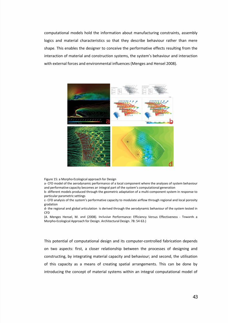
7/29/2019 AMSTERDAM SAVUNMA HATTININ DÖNÜŞTÜRÜLMESİNDE KILAVUZ OLARAK EDİMSEL MİMARLIK
http://slidepdf.com/reader/full/amsterdam-savunma-hattinin-doenuestueruelmesinde-kilavuz-olarak-edimsel 57/121

7/29/2019 AMSTERDAM SAVUNMA HATTININ DÖNÜŞTÜRÜLMESİNDE KILAVUZ OLARAK EDİMSEL MİMARLIK
http://slidepdf.com/reader/full/amsterdam-savunma-hattinin-doenuestueruelmesinde-kilavuz-olarak-edimsel 58/121
44
form, material, structure and behaviour as complex interrelations, rather than as
separate elements.
In their
computational
framework
there
are
three
essential
elements.
The
first
one
is
the
parametric set up based on the material system’s constraints. These parameters can only
be operated coherently with the constraints. The second element is the interaction of
individual system instances with external influences and forces. Therefore, the processes
that trigger and drive the advancing development of the system are the third constituent.
The integral computational model is, initially, an open model which is then informed, step
by step, by a series of additional parameters, restrictions and characteristics inferred
from material, fabrication and assembly logics and constraints. Only through these
processes the framework is able to operate coherently with the variable input to the
defining parameters (Menges 2007).
4.4.4 Need for yet to be Made Tools
As conclusion of the research done in this chapter about computational tools related with
performance, it can be seen that parametric design is well suited for material constraints,
environmental and
structural
factors
because
they
are
translatable
into
binary
code.
As
mentioned in previous chapters, the parametric model for performative architecture
needs to be directed further outwards, since it represents a shift in orientation in design.
The digital parameters should be used for environmental design and more, since the task
of performative architecture is not just designing less damaging relationships between
built and natural environments, but also to configure a built fabric that produces benefits.
Environmental and structural performances are obvious criteria that are included in
parametric
model.
However,
so
much
else
should
be
included.
By
means
of
parametric
models, many complex flows and relationships can be defined and the results of actions
can be foreseen. This is not for only environmental, but also true for cultural,
demographic, economic, and traffic flows. Since they have the same rules as natural
flows, they can also be mapped digitally and, to some extent, predicted digitally.
This sort of performative approach to design requires yet to be made digital tools that can
provide dynamic process of formation/generation based on specific performative aspects

7/29/2019 AMSTERDAM SAVUNMA HATTININ DÖNÜŞTÜRÜLMESİNDE KILAVUZ OLARAK EDİMSEL MİMARLIK
http://slidepdf.com/reader/full/amsterdam-savunma-hattinin-doenuestueruelmesinde-kilavuz-olarak-edimsel 59/121
45
of design. There are many digital analytical tools that can help the designer to assess
certain performative aspects of their projects after an initial design is formed. None of
those commercially available tools provide dynamic generative capabilities for conceptual
explorations during
architectural
design.

7/29/2019 AMSTERDAM SAVUNMA HATTININ DÖNÜŞTÜRÜLMESİNDE KILAVUZ OLARAK EDİMSEL MİMARLIK
http://slidepdf.com/reader/full/amsterdam-savunma-hattinin-doenuestueruelmesinde-kilavuz-olarak-edimsel 60/121
46
CHAPTER 5
GENERAL CHARACTER OF THE DEFENCE LINE AND ITS TRANSFORMATION
This thesis deals with performative architecture to address a model of design to generate
transformation alternatives for a current design problem of Dutch Landscapes. This
design problem is the transformation of the Defence Line of Amsterdam. The
transformation includes conservation of 41 forts, assigning them new functions and
designing additions.
Defence Line of Amsterdam (Dutch name Stelling van Amsterdam) is a 135 km long ring of
fortifications around Amsterdam, constructed between 1880 and 1920. It consists of 42
forts located between 10 to 15 kilometres from the centre, as shown in Figure 16a, and
lowlands that can easily be flooded in time of war. The flooding was designed to give a
depth of about 30 cm, insufficient for boats to traverse. Despite the fact that only the
forts might be seen as the most visible part, Defence Line needs to be understood as a
logistical system,
in
combination
with
the
circle
of
flooded
areas
(Figure
16b).
Figure 16 Defence Line of Amsterdam
a‐ diagram of the general configuration b‐ satellite view of the possible circle of flooded areas (http://www.stelling‐amsterdam.nl/english/forts/index.html Last accessed 10 January 2011)
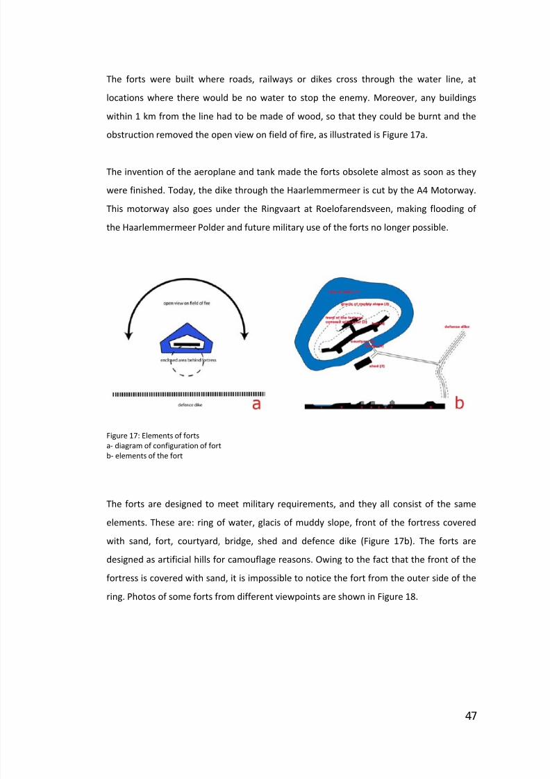
7/29/2019 AMSTERDAM SAVUNMA HATTININ DÖNÜŞTÜRÜLMESİNDE KILAVUZ OLARAK EDİMSEL MİMARLIK
http://slidepdf.com/reader/full/amsterdam-savunma-hattinin-doenuestueruelmesinde-kilavuz-olarak-edimsel 61/121
47
The forts were built where roads, railways or dikes cross through the water line, at
locations where there would be no water to stop the enemy. Moreover, any buildings
within 1 km from the line had to be made of wood, so that they could be burnt and the
obstruction removed
the
open
view
on
field
of
fire,
as
illustrated
is
Figure
17a.
The invention of the aeroplane and tank made the forts obsolete almost as soon as they
were finished. Today, the dike through the Haarlemmermeer is cut by the A4 Motorway.
This motorway also goes under the Ringvaart at Roelofarendsveen, making flooding of
the Haarlemmermeer Polder and future military use of the forts no longer possible.
Figure 17: Elements of forts a‐ diagram of configuration of fort b‐ elements of the fort
The forts are designed to meet military requirements, and they all consist of the same
elements. These are: ring of water, glacis of muddy slope, front of the fortress covered
with sand, fort, courtyard, bridge, shed and defence dike (Figure 17b). The forts are
designed as artificial hills for camouflage reasons. Owing to the fact that the front of the
fortress is covered with sand, it is impossible to notice the fort from the outer side of the
ring. Photos of some forts from different viewpoints are shown in Figure 18.
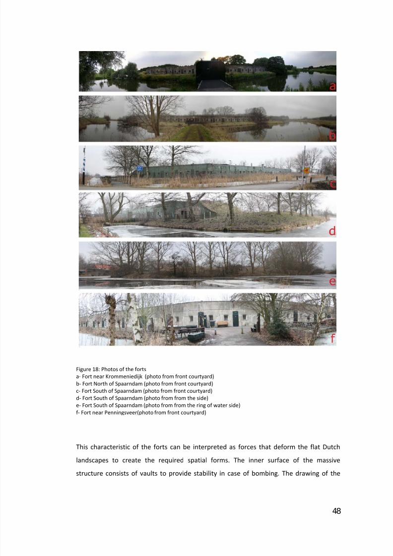
7/29/2019 AMSTERDAM SAVUNMA HATTININ DÖNÜŞTÜRÜLMESİNDE KILAVUZ OLARAK EDİMSEL MİMARLIK
http://slidepdf.com/reader/full/amsterdam-savunma-hattinin-doenuestueruelmesinde-kilavuz-olarak-edimsel 62/121
48
Figure 18: Photos of the forts a‐ Fort near Krommeniedijk (photo from front courtyard) b‐ Fort North of Spaarndam (photo from front courtyard)
c‐Fort
South
of
Spaarndam
(photo
from
front
courtyard)
d‐ Fort South of Spaarndam (photo from from the side) e‐ Fort South of Spaarndam (photo from from the ring of water side) f ‐ Fort near Penningsveer(photo from front courtyard)
This characteristic of the forts can be interpreted as forces that deform the flat Dutch
landscapes to create the required spatial forms. The inner surface of the massive
structure consists of vaults to provide stability in case of bombing. The drawing of the

7/29/2019 AMSTERDAM SAVUNMA HATTININ DÖNÜŞTÜRÜLMESİNDE KILAVUZ OLARAK EDİMSEL MİMARLIK
http://slidepdf.com/reader/full/amsterdam-savunma-hattinin-doenuestueruelmesinde-kilavuz-olarak-edimsel 63/121
49
section and front view are illustrated in Figure 19. The building is designed to be self
sustainable. For example, water on the sand side of the fort can be collected and used in
order to survive under enemy attacks. Although the forts are designed with a
functionalist sense,
they
create
innovative
forms
in
Dutch
landscape;
so
they
can
be
seen
as performative architecture of the era in which they were built.
Figure 19: Section and front views of the forts
5.1 Today and Future of the Defence Line
Today, the influence of the Defence Line is remarkable. The army is scarcely present but
the country planning and infrastructure can largely be attributed to the Defence Line.
Because of a special law, building along the Defence Line has hardly taken place and new
rail and roadways had to run along the forts. The Defence Line was inscribed to the
UNESCO World Heritage List in 1996 because of its historic value for all mankind
(UNESCO/WHC 2011). Moreover, they are important elements of Dutch landscape by
creating rich landscapes while demonstrating a unique historic example of defence and
water‐management technology.
Presently, almost all forts remain in good condition. Only two forts are fully demolished,
and interest in the Defence Line and its preservation was ignited after the demolition of

7/29/2019 AMSTERDAM SAVUNMA HATTININ DÖNÜŞTÜRÜLMESİNDE KILAVUZ OLARAK EDİMSEL MİMARLIK
http://slidepdf.com/reader/full/amsterdam-savunma-hattinin-doenuestueruelmesinde-kilavuz-olarak-edimsel 64/121
50
the main building of Fort near Velsen by the company owning it. Recently, a very limited
number of forts have been renovated. These renovations were achieved mainly by
private investors transforming the forts into house restaurants and wine trading
companies. The
fort
near
De
Kwakel,
which
is
now
surrounded
by
the
village
and
the
terrain, is also used for housing. The fort watchmen's house and engineering shed are
converted into houses.
Following 1996, after being inscribed as the UNESCO World Heritage List, privatization of
the forts had given way to their allocation to charitable organizations. For instance, forts
along the Drecht and Vijfhuizen are owned by charitable foundations and are now in use
as restaurants, galleries and workshops. The fort along Den Ham is being established as a
volunteer Defence Museum and the fort near Veldhuis in renovated as the Air Warfare
Museum of the Aircraft Recovery Group Association (Stelling Amsterdam 2010).
Besides these, some of the forts are used for various purposes without being renovated
such as, sport shooting, fire brigade training centre (Fort near Marken‐Binnen), industrial
estate (Fort north of Uitgeest), distribution centre for the transport of valuables (Fort
near the Liebrug) a yachting‐club for retired military personnel (Fort near Kudelstaart).
Figure 20
illustrates
the
recent
situation
of
the
forts
along
with
photos
of
some
recent
functions attributed to them.
The transformation of the Defence Line should not be understood as renovating the forts
and assigning them new functions individually. As mentioned above, the original design of
Defence Line involves a holistic understanding; therefore, redesigning the Defence Line
requires defining a general guideline rather than focusing on its parts separately. For this
reason,
performative
architecture
is
used
to
define
a
guideline
for
the
generation
of
alternatives for this recent design problem of Dutch Landscapes. To define a guideline for
the transformation of the Defence Line, an analysis of the whole site in urban scale is
needed in relation to future scenarios of the Randstad.
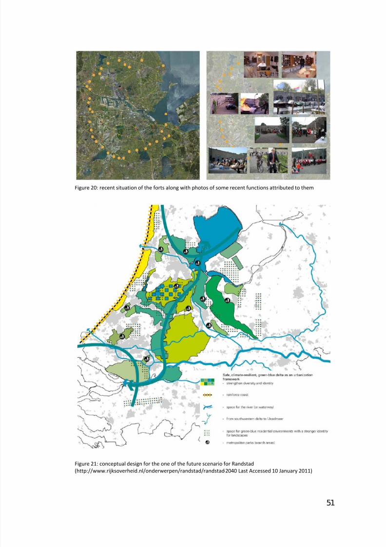
7/29/2019 AMSTERDAM SAVUNMA HATTININ DÖNÜŞTÜRÜLMESİNDE KILAVUZ OLARAK EDİMSEL MİMARLIK
http://slidepdf.com/reader/full/amsterdam-savunma-hattinin-doenuestueruelmesinde-kilavuz-olarak-edimsel 65/121
51
Figure 20: recent situation of the forts along with photos of some recent functions attributed to them
Figure 21: conceptual design for the one of the future scenario for Randstad
(http://www.rijksoverheid.nl/onderwerpen/randstad/randstad‐2040 Last Accessed 10 January 2011)
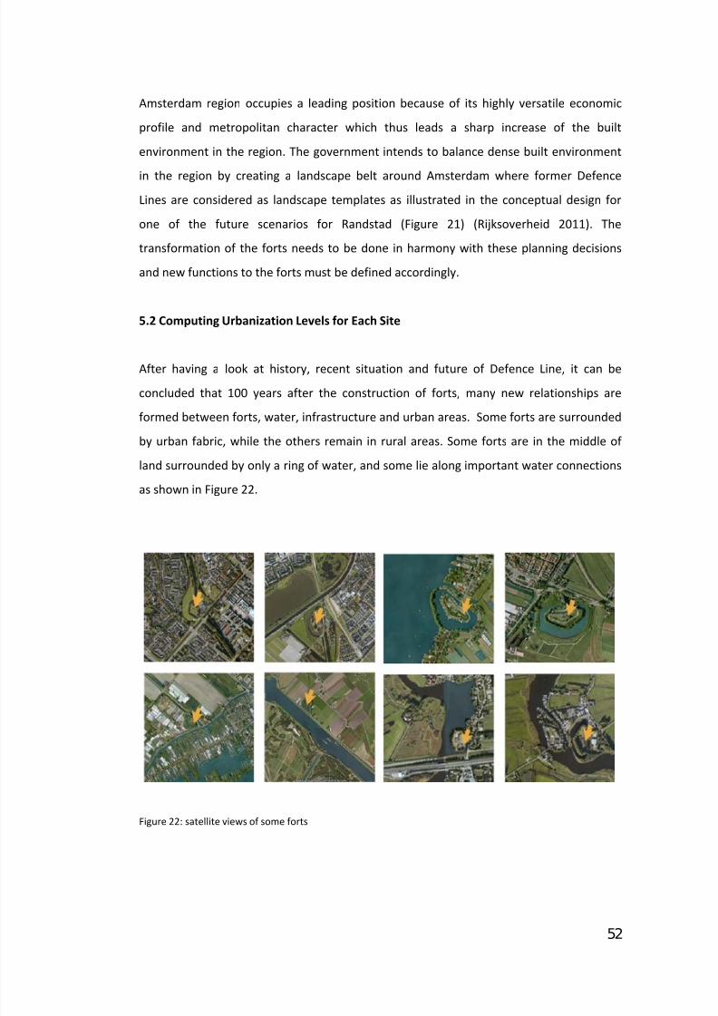
7/29/2019 AMSTERDAM SAVUNMA HATTININ DÖNÜŞTÜRÜLMESİNDE KILAVUZ OLARAK EDİMSEL MİMARLIK
http://slidepdf.com/reader/full/amsterdam-savunma-hattinin-doenuestueruelmesinde-kilavuz-olarak-edimsel 66/121
52
Amsterdam region occupies a leading position because of its highly versatile economic
profile and metropolitan character which thus leads a sharp increase of the built
environment in the region. The government intends to balance dense built environment
in the
region
by
creating
a landscape
belt
around
Amsterdam
where
former
Defence
Lines are considered as landscape templates as illustrated in the conceptual design for
one of the future scenarios for Randstad (Figure 21) (Rijksoverheid 2011). The
transformation of the forts needs to be done in harmony with these planning decisions
and new functions to the forts must be defined accordingly.
5.2 Computing Urbanization Levels for Each Site
After having a look at history, recent situation and future of Defence Line, it can be
concluded that 100 years after the construction of forts, many new relationships are
formed between forts, water, infrastructure and urban areas. Some forts are surrounded
by urban fabric, while the others remain in rural areas. Some forts are in the middle of
land surrounded by only a ring of water, and some lie along important water connections
as shown in Figure 22.
Figure 22: satellite views of some forts

7/29/2019 AMSTERDAM SAVUNMA HATTININ DÖNÜŞTÜRÜLMESİNDE KILAVUZ OLARAK EDİMSEL MİMARLIK
http://slidepdf.com/reader/full/amsterdam-savunma-hattinin-doenuestueruelmesinde-kilavuz-olarak-edimsel 67/121
53
The first step of transforming the Defence Line as a green belt is to analyze relationships
between forts and the whole system of the area. Concentration of infrastructure and
urbanization affect the number of potential users for each fort; therefore, the scale of the
transformation and
the
size
of
needed
additions
differ.
Eventually,
the
definition
of
the
guideline for the transformation is initiated by a parametric model that computes
urbanization levels for the sites of the forts.
The aim of this parametric model is to calculate urbanization levels for the region of
Defence Line using waterlines, land transportation connections (rail lines and highways),
urban areas, Schiphol airport noise level contours, green zones (forests, nature reserves
and recreation areas), and greenhouses as inputs (Figure 23). As a result, the
concentration of infrastructure and urbanization are computed. One important point in
computing this kind of concentration is to define the strength and area of influence for
each kind of input.
Grasshopper® software, which is a graphical algorithm editor tightly integrated with
Rhino’s 3‐D modelling tools, is used for the ease it offers in manipulations of the input.
The fundamental logic behind the parametric urban model is very simple: a surface
populated with
boxes
whose
height
varies
in
relationship
to
an
attractor
point.
To start with, a surface that covers the region is created and divided into a grid. Then, the
input data mentioned above is used to deform the height of the grid cells successively.
The inputs, whether lines or surfaces, are turned into points, so that the distance
between each point to the grid can be calculated for the step of deforming the heights.

7/29/2019 AMSTERDAM SAVUNMA HATTININ DÖNÜŞTÜRÜLMESİNDE KILAVUZ OLARAK EDİMSEL MİMARLIK
http://slidepdf.com/reader/full/amsterdam-savunma-hattinin-doenuestueruelmesinde-kilavuz-olarak-edimsel 68/121
54
Figure 23: different inputs to calculate the urban levels for the region of Defence Line
These inputs are: waterlines, rail lines, highways, urban areas, Schiphol airport noise level contours, green
zones (forests, nature reserves and recreation areas), and greenhouses
Two other factors are also used for the deformation: the strength and area of influence
(Figure24). The “number sliders”, which is a component offered by the Grasshopper®
programme for the manipulation of the input, is used to control these two values. The
designer determines the importance of the specified input in the computation of urban
levels by controlling the height of the deformation of grid cells. This control is done by the
number slider which is called strength. Similarly, the area of the influence of the specified
input is determined by controlling a number slider called area.

7/29/2019 AMSTERDAM SAVUNMA HATTININ DÖNÜŞTÜRÜLMESİNDE KILAVUZ OLARAK EDİMSEL MİMARLIK
http://slidepdf.com/reader/full/amsterdam-savunma-hattinin-doenuestueruelmesinde-kilavuz-olarak-edimsel 69/121
55
Figure 24: different influences of the controls ‘area of influence’ and ‘strength’
Strength and area values are defined for each kind of input, as shown in Figure 25. The
inputs that increase the urbanization levels and size of additions to forts are waterlines,
rail lines, highways, urban areas and greenhouses. Waterlines have the biggest influence.
Due to the fact that transformation of the Defence Line requires to be understood as a
system, waterlines
play
a significant
role
in
connecting
the
forts.
The
forts
which
have
a
direct connection to waterlines gain priority in the transformation process.

7/29/2019 AMSTERDAM SAVUNMA HATTININ DÖNÜŞTÜRÜLMESİNDE KILAVUZ OLARAK EDİMSEL MİMARLIK
http://slidepdf.com/reader/full/amsterdam-savunma-hattinin-doenuestueruelmesinde-kilavuz-olarak-edimsel 70/121
56
Figure 25: Different definitions of ‘area of influence’ and ‘strength’ for different inputs
The inputs that decrease the urbanization level and the size of additions to forts are
Schiphol airport noise level contours and green zones. In order to cover the whole area
under the impact of the noise of Schiphol airport, the biggest value for area of influence is
given to this input. The green zones are used as a reducing factor to constrain the size of
addition to the forts that are in forests, nature reserves and recreation areas.

7/29/2019 AMSTERDAM SAVUNMA HATTININ DÖNÜŞTÜRÜLMESİNDE KILAVUZ OLARAK EDİMSEL MİMARLIK
http://slidepdf.com/reader/full/amsterdam-savunma-hattinin-doenuestueruelmesinde-kilavuz-olarak-edimsel 71/121
57
Figure 26: process for the waterlines a‐ print screen from Grasshopper® b‐ grid lines and first input: waterlines c‐ output of the first step
Figure 26 illustrates the process for waterlines. The grid, illustrated in Figure 26b, is
deformed by the input of waterlines and differentiated height of grid cells are formed as
an output. In the end, the urbanization levels for each site are computed by adding the
deformation values of each input. This urbanization level is used to give an understanding
of the number of potential users, the scale of the transformation and the size of needed
additions for each fort. The result is shown in Figure 27.

7/29/2019 AMSTERDAM SAVUNMA HATTININ DÖNÜŞTÜRÜLMESİNDE KILAVUZ OLARAK EDİMSEL MİMARLIK
http://slidepdf.com/reader/full/amsterdam-savunma-hattinin-doenuestueruelmesinde-kilavuz-olarak-edimsel 72/121
58
Figure 27:
final
output
of
the
model
5.3 Defining New Functions and Additions
The defence Line is transformed into a green belt around Amsterdam as indicated in
planning decisions. Accordingly, the forts are transformed into nature parks and botanical
gardens. However, as seen in the calculation of urbanization levels, the character of the
sites varies greatly.
The forts within the sites with high urban levels will be selected as transit points. They will
become official visitor centres and all the forts will be connected by boat tours, biking and
hiking trails. Guided tours take the visitors through this green belt around Amsterdam.
The forts that host the visitor centres will provide a wider range of activities. They will be
used by two groups of users; those that use the fort as a transfer area that connects the
7/29/2019 AMSTERDAM SAVUNMA HATTININ DÖNÜŞTÜRÜLMESİNDE KILAVUZ OLARAK EDİMSEL MİMARLIK
http://slidepdf.com/reader/full/amsterdam-savunma-hattinin-doenuestueruelmesinde-kilavuz-olarak-edimsel 73/121
59
urban elements within the site, and those that aim to do sight‐seeing and spend time
around the fort. The forts with low urbanization values will be used by a small number of
users such as locals living in neighbourhood and biking or hiking trail groups.
The relationship of the urbanization levels and complexity of the activities shows an
exponential relationship. The simplest functions are the ones that provide space for basic
human activities like: walk, relax, sit, climb, play, picnic, sleep, eat, talk, swim and
sunbathe. Complex functions hold cultural, commercial and educational activities. The
botanical displays in the interior of the forts educate visitors to the region's flora. They
provide workshop spaces where visitors can experience and learn how to grow plants or
places for presentations to increase environmental awareness.
The complexity of the function defines the size of addition needed. For basic activities,
the additions can be urban furniture, a floor or a roof structure. For instance, some
structures provide shade and shelter, while some only provide suitable seating areas.
Closed spaces are needed only for more complex functions, which can also be used to
create suitable spaces for what are, basically, greenhouses or the compartmentalization
of nature by humans.
These additions are designed as stripes, similar to the design of the forts. As previously
mentioned, the forts needed to be camouflaged from the outside of the water ring
(Figure 28a). The front of the fort is covered with sand so that they look like little hills that
lie along the flat Dutch landscape. This character of the forts is very inspirational for the
initial design ideas. In this manner the form of the fort and the islet in which the fort lies
are interpreted as deformed stripes (Figure 28c). The forts are designed as artificial hills
that
meet
the
requirements
of
the
weapons
and
soldiers
that
would
use
the
fort
(Figure
28b). Similarly, the complexity of function and needed space, (in relation with the
computation of urban levels) deforms flat land into stripes to meet the spatial
requirements.
There are two additional objectives of the deformed stripes besides providing a setting
for various activities. These are adding an extra layer to the existing topography of the
islet while connecting it to the existing urban elements and landscape behind the dike.

7/29/2019 AMSTERDAM SAVUNMA HATTININ DÖNÜŞTÜRÜLMESİNDE KILAVUZ OLARAK EDİMSEL MİMARLIK
http://slidepdf.com/reader/full/amsterdam-savunma-hattinin-doenuestueruelmesinde-kilavuz-olarak-edimsel 74/121
60
Therefore, the additions have not itself been made independent, but have been
connected with the different pieces of land, landscape and nature. Also with the new
topography, they aim to become "hill‐like architecture" with a continuation between
indoor and
outdoor
space.
The
stripe’s
integration
of
existing
urban
structure,
architecture and landscape is a strategy for creating a recreational and educational place
for visitors.
Figure 28: the camouflage of the fort as an inspiration for the design
a‐ satellite view showing the camouflage of the fort b‐ reinterpretation of the design of fort: stripes of land are deformed to meet the requirements of the functions c‐ deformed stripes for the design of new building
5.4 Defining Performance Criteria
The objective of this thesis is to address performative architecture as guideline for the
transformation of the whole Defence Line. After the urban analysis of the site and
configuring the initial ideas about the design, we can start the definition of the guideline
by setting up a hierarchy of the performance criteria for the transformation. In chapter
four, building performance criteria were divided into three. The sub categories of
7/29/2019 AMSTERDAM SAVUNMA HATTININ DÖNÜŞTÜRÜLMESİNDE KILAVUZ OLARAK EDİMSEL MİMARLIK
http://slidepdf.com/reader/full/amsterdam-savunma-hattinin-doenuestueruelmesinde-kilavuz-olarak-edimsel 75/121
61
performance criteria for transforming The Defence Line of Amsterdam as a green belt, are
defined as the following three:
1‐health, safety and security performance
‐structural
‐illuminative
After computing urbanization levels, different functions are assigned to different sites.
However, since this design model aims to deal with the Defence Line as a whole, the
additions must be done using the same language. For this reason, design of the structure
is done with parameters, which are fed with the input that are related with site and
assigned functions. Thus the structure can adapt its form from smaller spans to bigger
spans while creating space for different functions.
Another performance criterion of transforming the Defence Line into a green belt is the
preservation of nature. The proposed additions should not damage the natural richness
of the area. They should conserve and contribute to nature while providing suitable and
diverse conditions for human habitation. Solar analyses of the designs are carried out to
see if they let through enough sunlight for the nutrition of plants on the site.
2‐functional, efficiency performance
‐provide adequate space for required functions
‐provide connections between urban elements of site
Due to the fact that these forts lost their original military function, new functions need to
be defined for them, so that the space they define can be utilized in a new way. The
required
spaces
for
new
functions
are
improved
by
providing
additions
which
also
connect the fort to the existing urban elements and landscape behind the dike. The
additions play an important role in connecting the islet of the fort to the surrounding.
3‐psychological, social, cultural and aesthetic performance
‐conservation of the UNESCO Heritage site
‐compatibility with the surrounding
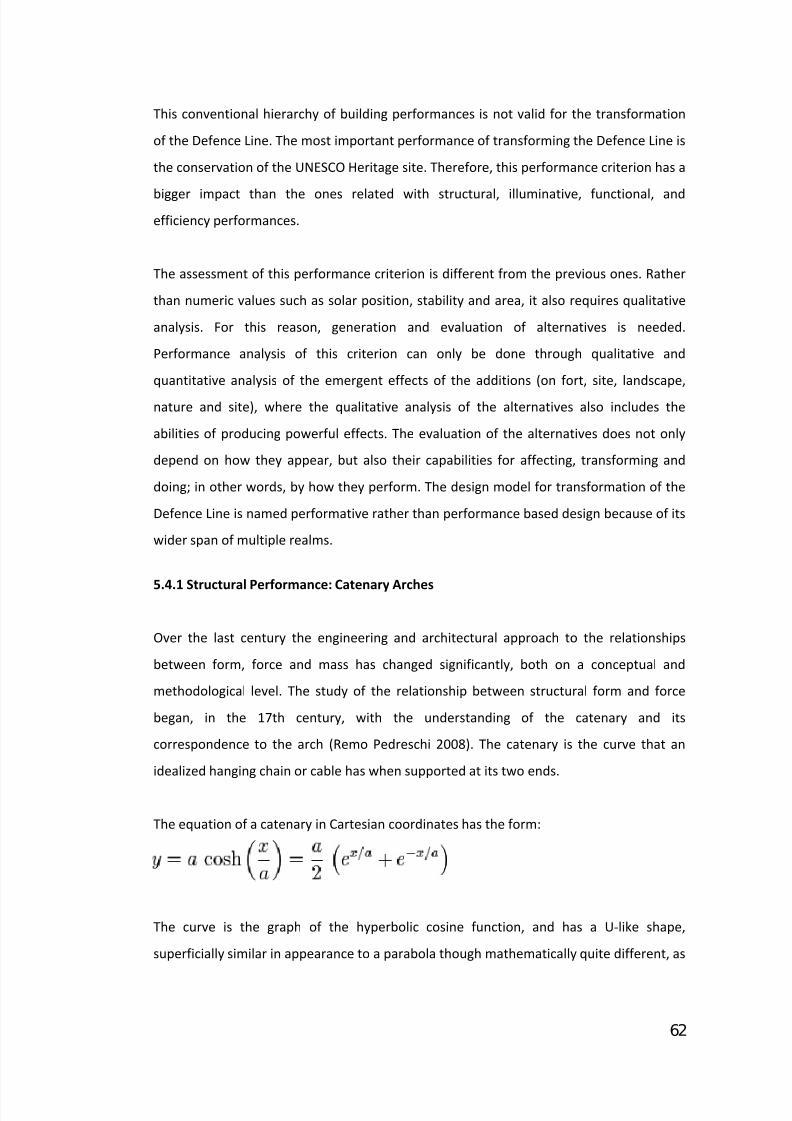
7/29/2019 AMSTERDAM SAVUNMA HATTININ DÖNÜŞTÜRÜLMESİNDE KILAVUZ OLARAK EDİMSEL MİMARLIK
http://slidepdf.com/reader/full/amsterdam-savunma-hattinin-doenuestueruelmesinde-kilavuz-olarak-edimsel 76/121
62
This conventional hierarchy of building performances is not valid for the transformation
of the Defence Line. The most important performance of transforming the Defence Line is
the conservation of the UNESCO Heritage site. Therefore, this performance criterion has a
bigger impact
than
the
ones
related
with
structural,
illuminative,
functional,
and
efficiency performances.
The assessment of this performance criterion is different from the previous ones. Rather
than numeric values such as solar position, stability and area, it also requires qualitative
analysis. For this reason, generation and evaluation of alternatives is needed.
Performance analysis of this criterion can only be done through qualitative and
quantitative analysis of the emergent effects of the additions (on fort, site, landscape,
nature and site), where the qualitative analysis of the alternatives also includes the
abilities of producing powerful effects. The evaluation of the alternatives does not only
depend on how they appear, but also their capabilities for affecting, transforming and
doing; in other words, by how they perform. The design model for transformation of the
Defence Line is named performative rather than performance based design because of its
wider span of multiple realms.
5.4.1
Structural
Performance:
Catenary
Arches
Over the last century the engineering and architectural approach to the relationships
between form, force and mass has changed significantly, both on a conceptual and
methodological level. The study of the relationship between structural form and force
began, in the 17th century, with the understanding of the catenary and its
correspondence to the arch (Remo Pedreschi 2008). The catenary is the curve that an
idealized hanging chain or cable has when supported at its two ends.
The equation of a catenary in Cartesian coordinates has the form:
The curve is the graph of the hyperbolic cosine function, and has a U‐like shape,
superficially similar in appearance to a parabola though mathematically quite different, as

7/29/2019 AMSTERDAM SAVUNMA HATTININ DÖNÜŞTÜRÜLMESİNDE KILAVUZ OLARAK EDİMSEL MİMARLIK
http://slidepdf.com/reader/full/amsterdam-savunma-hattinin-doenuestueruelmesinde-kilavuz-olarak-edimsel 77/121
63
shown in Figure 29a. All catenary curves are controlled by chain length and position of the
supports. Figure 29b illustrates changing the parameter a is equivalent to a change in the
position of supports within the same chain length.
If the curve of the cable is flipped around its anchor points, the resulting geometry is the
corresponding ideal form for an arch resulting in uniform axial compressive forces. The
arch endures almost pure compression, in which no significant bending moment occurs
inside the material.
Figure 29: graph of catenary equation
a‐ parabola versus catenary b‐graphs
of
catenary
equation
in
relation
to
variable
a
(http://en.wikipedia.org/wiki/Catenary Last accessed 10 10 January 2011)
The roof of the Taq‐i Kisra in ancient city of Ctesiphon (Iraq today) constructed in 540 AD
was one the largest vaults constructed at the time (Julian 1999). As illustrated in Figure
30, the vault is roughly a catenary. The vault spans 24 meters with an arch height of 16.6
meters, supported on vertical faced buttress walls with a height of 11.1 meters. To study
the relationships between form of the arch and resultant stresses the following
calculations are
done
using
iDiana
software,
which
is
a finite
element
analysis
program.

7/29/2019 AMSTERDAM SAVUNMA HATTININ DÖNÜŞTÜRÜLMESİNDE KILAVUZ OLARAK EDİMSEL MİMARLIK
http://slidepdf.com/reader/full/amsterdam-savunma-hattinin-doenuestueruelmesinde-kilavuz-olarak-edimsel 78/121
64
Figure 30: photo of Taq‐i Kisra (http://en.wikipedia.org/wiki/Catenary Last accessed 10 10 January 2011)
The aim is to compare stresses in the Taq‐i Kisra assuming either a catenary or parabolic
profile. Also constant depth sections are compared with increasing in depth towards the
supports. The section depth was taken as 0.85 metres, increasing to 1.7 metres at the
supports for the variable depth profiles. Four analyses were carried out as illustrated in
Figure 31:
Run 1: Catenary with varying section depth
Run 2: Catenary with constant section depth
Run 3: Parabola with varying section depth
Run 4: Parabola with constant section depth
Figure 31: Run 1,3 and Run 2,4 (http://newtonexcelbach.wordpress.com Last accessed 10 10 January 2011)

7/29/2019 AMSTERDAM SAVUNMA HATTININ DÖNÜŞTÜRÜLMESİNDE KILAVUZ OLARAK EDİMSEL MİMARLIK
http://slidepdf.com/reader/full/amsterdam-savunma-hattinin-doenuestueruelmesinde-kilavuz-olarak-edimsel 79/121
65
Bending moments and axial stresses for these four runs are illustrated in the graph in
Figure 32. It can be seen that axial forces are similar, with the constant depth sections
having a significantly smaller force. Bending moments for the constant depth catenary
(Run 2)
are
close
to
zero
throughout.
Bending
moments
for
the
constant
depth
parabola
(Run 4) and the variable depth catenary (Run 1) are similar, with a maximum of 50
kNm/m. The variable depth parabola (Run 3) had bending moments more than twice as
high.
Figure 32: Results of bending moment and axial force (http://newtonexcelbach.wordpress.com Last accessed 10 10 January 2011)
Axial stresses for these four runs are shown in Figure 33. It can be seen that stresses are
compressive throughout for Run 2, and tensile stresses increases progressively through
Runs 1, 4 and 3 respectively. The maximum tensile stress from Run 3 is 400 kPa, which
would leave little reserve capacity for wind or earthquake loads.
This comparison between catenary and parabolic curve proves that catenary with
constant section depth is an ideal curve form for arch structures. Since the bending
moments are almost zero and maximum tensile stress was about four times smaller for
the catenary profile than the parabolic profile. Therefore catenary arches are used as a
main definition to generate the forms of additions to the forts of the Defence Line of
Amsterdam.
The parameters in the catenary arch equation are fed with the inputs that are related
with functions and site. Consequently structural performance is attributed to the

7/29/2019 AMSTERDAM SAVUNMA HATTININ DÖNÜŞTÜRÜLMESİNDE KILAVUZ OLARAK EDİMSEL MİMARLIK
http://slidepdf.com/reader/full/amsterdam-savunma-hattinin-doenuestueruelmesinde-kilavuz-olarak-edimsel 80/121
66
morphological advantages of this ideal form; the catenary arches are proper to create the
desired effects of the conceptual design. Deformed stripes which will act as an extra layer
to existing topography can be obtained from series of catenary arches.
Figure 33: Stresses (http://newtonexcelbach.wordpress.com Last accessed 10 10 January 2011)
5.4.2 Illuminative
Performance:
Categorization
of
Plants
According
to
Needed
Sunlight
The Netherlands has a variety of nature reserves and diverse fauna. According to the
statics of World Resources Institute, Netherland’s ecosystem shows the following
distribution: forest 2%, crop/grass vegetation 88%, urban and built up area 4%, wetlands
and water bodies 6% (World Resources Institute 2007). As mentioned in chapter 5.2, the
135 ring of Defence Line of Amsterdam is in the presence of all those different types of
ecosystems. All forts have a relationship with water bodies, some lie within urban areas

7/29/2019 AMSTERDAM SAVUNMA HATTININ DÖNÜŞTÜRÜLMESİNDE KILAVUZ OLARAK EDİMSEL MİMARLIK
http://slidepdf.com/reader/full/amsterdam-savunma-hattinin-doenuestueruelmesinde-kilavuz-olarak-edimsel 81/121
67
while some lie along natural vegetation. Consequently, one of the most important
performance criteria in the design of the transformation Defence Line as a green belt is
the conservation of nature. Data about existing flora around the islet of the forts and the
optimum sunlight
angles/amounts
for
the
nutrition
of
those
plants
are
important.
Landscape architects divide plants into 3 classes according to their needs for sun, as
illustrated in Figure 34. These are: full sun plants, little sun plants and shade plants. Little
sun plants have two sub classes: morning sun and afternoon sun. Full sun plants require
sun exposure and should be planted to take in as much of it as possible. Little sun and
shade plants grow well in cool and moist environments. These plants need morning sun;
weaker, gentler and more pleasant than the much brighter, harsher and intense
afternoon sun. Three hours of direct afternoon sun will fry most full shade plants.
The mapping between the ecosystem classification of Word Resources Institute and the
classes of the plants according to sun exist to inform the performative design model for
the transformation of the Defence Line of Amsterdam.
5.4.2.1 Woody Plants
The common woody plants that grow in Holland are oak, pine, elm, little leaf linden and
beech. Scrubs such as: Crataegus, (hawthorn or thornapple) are classified under woody
plants. Evergreens, deciduous tress and shrubs, they all do great in full afternoon sun.
5.4.2.2 Grassland
Except
cropland
and
woody
plants,
the
natural
vegetation
of
Holland
is
generally
based
on grassland and flowering plants (both wild and cultivated ones). The main types pf
grasses are: Poaceae (true grasses), Juncaceae (rushes) and Cyperaceae (sedges).
Some examples for flowering plants that grow in Holland are: Achillea millefoliu ( yarrow) ,
Asteraceae (Daisy), Campanula rotundifolia (Harebell), Centaurea jacea (Brown
Knapweed), Potentilla, Convolvulus arvensis (Field Bindweed), Crepis (Hawksbeard),
Allium vineale (Wild Garlic, Crow Garlic), Galium verum (Yellow Bedstraw)

7/29/2019 AMSTERDAM SAVUNMA HATTININ DÖNÜŞTÜRÜLMESİNDE KILAVUZ OLARAK EDİMSEL MİMARLIK
http://slidepdf.com/reader/full/amsterdam-savunma-hattinin-doenuestueruelmesinde-kilavuz-olarak-edimsel 82/121
68
Grasses and flowering plants, except the cereals, grow in moist and moderate climates
and prefer diffused light. Direct sunlight exposure fades the colour of the leaves and
flowers. The best treatment to get the better results is sun exposure during morning and
watering in
the
afternoon
shade.
5.4.2.3 Water Bodies
The configuration of forts (each is on an islet surrounded by water) creates a combination
of water and wetland ecosystem. The flora of wetlands around the forts consists of:
Lychnis flos‐cuculi, (Ragged Robin), Prunella vulgaris (selfheal), Phragmites (common
reed), Veronica (speedwell, gypsy weed), Sagittaria sagittifolia (arrowhead) ( Vesters and
Baas 2003). This flora provides a habitat for birds such as kingfisher, grebe and duck. For
the fauna and flora of wetlands dehydration is not a problem. This makes water land
ecosystem tolerant to strong sun; on the other hand, the design of closed spaces for
these ecosystems must prevent strong sun exposure to eliminate moisture due to
evaporation. Accordingly, the most appropriate sun exposure for closed spaces
containing water bodies is morning sun.
5.5.2.4 Micro
climates
The camouflage characteristic of the forts creates a special microclimate. The back of the
fort which is covered with sand provides additional shadow and moisture. Some examples
of the flora of the surrounding of the fort are: Viola odorata (sweet violet), Thyme, Vicia
(vetches), and Echium vulgare (Blueweed). ( Vesters and Baas 2003).
As
a
conclusion,
one
of
the
main
goals
of
the
transformation
of
the
Defence
Line
of
Amsterdam is the preservation of the natural richness of the area. While designing an
addition to the forts, the specific sunlight needs of the plants must be incorporated. Only
in this way the shadow of the additional building can be prevented from destroying the
flora.
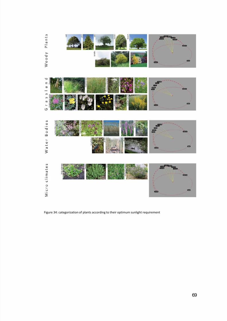
7/29/2019 AMSTERDAM SAVUNMA HATTININ DÖNÜŞTÜRÜLMESİNDE KILAVUZ OLARAK EDİMSEL MİMARLIK
http://slidepdf.com/reader/full/amsterdam-savunma-hattinin-doenuestueruelmesinde-kilavuz-olarak-edimsel 83/121
69
Figure 34: categorization of plants according to their optimum sunlight requirement

7/29/2019 AMSTERDAM SAVUNMA HATTININ DÖNÜŞTÜRÜLMESİNDE KILAVUZ OLARAK EDİMSEL MİMARLIK
http://slidepdf.com/reader/full/amsterdam-savunma-hattinin-doenuestueruelmesinde-kilavuz-olarak-edimsel 84/121
70
CHAPTER 6
PERFORMATIVE DESIGN MODEL
The transformation of the Defence Line of Amsterdam involves the transformation of 42
forts, which show similar characteristics but also some disparities. Due to the fact that the
location of the forts is different, they require different transformations. A parametric
model is defined for the transformation which consists of a series of parametric models
through the design stages. This model is named ‘performative design model’ by the
author. The
choice
of
using
parametric
techniques
is
based
on
their
capacity
for
creating
design alternatives while managing the complex system of relationships. In other words,
once parametric models are introduced, different design alternatives for different forts
can be computed rapidly, in order to explore variations within their design solution space.
The performative design model is introduced to manage a network of dependency
relationships between different stages of design. Through the parametric model a
network of
dependencies
is
described
using
two
kinds
of
attributes,
dependent
and
independent. The first kind is described by independent values which are inputs to the
model. The other attributes are the ones that vary in relation to other attributes. The
dependent attributes receive data from their related attributes. This flow of data keeps
the network of dependencies consistent. While it remains constant, it processes the input
values by generating variations of the output. These variations are produced as different
solutions of the model and are called instances of the model (Turrin and Kilian 2009).
Grasshopper® software, which is used for the parametric design, allows the visualization
of the network of dependencies along with the visualization of the geometry. Since
besides the outputs, both inputs and data flow are also kept explicit, the designer is
capable of both controlling the parameters and the dependencies of the network. If the
designer does not like the results, he can adjust the parameters and the rules until they
meet the initial objectives.

7/29/2019 AMSTERDAM SAVUNMA HATTININ DÖNÜŞTÜRÜLMESİNDE KILAVUZ OLARAK EDİMSEL MİMARLIK
http://slidepdf.com/reader/full/amsterdam-savunma-hattinin-doenuestueruelmesinde-kilavuz-olarak-edimsel 85/121
71
6.1 Parameterization and Articulation of the Model
In the
previous
section,
the
potentials
of
parametric
techniques
for
generating
geometrical alternatives are discussed. These potentials amplify the geometrical
representation by providing a model of the design which is actually a large set of possible
configurations of the parameters and dependencies. While working with such a complex
system, the parametric models are introduced in stages. If it was a single compound
model, it would take more time to compute for every simple parameters change. Instead,
dividing the model into stages provides ease of intervention to the rules and parameters,
while shortening computation time. The performative design model for the
transformation is articulated in four stages which are parallel to the stages of a
conventional design process. These stages are: regional design (1/50.000); urban design
(1/1.000); building design (1/200); and the production of scale models.
After the definition of design states, the effort is moved directly to two other levels of the
design: one is the parameterization process, which is preliminary to the computational
generation of alternative solutions; the other one is the selection process among the
large set
of
generated
instances.
Parameterization
is
the
fundamental
step.
It
is
required
to exploit the potential and advantages offered by parametric modelling. They are the
definitions of the components of the model that vary and how this variation occurs. In
other words, parameterization determines the attributes and the rules they are subject to
follow (Turrin and Kilian 2009).
Parameterization describes the dependency chain used in the model, starting from
independent
parameters.
The
conceptual
structure
defined
during
the
parameterization
process is in fact the one that guides and determines the variation of the geometrical
output. The result of the parameterization process is a dependency chain described as a
hierarchical structure. This makes the earlier choice of model focus so important. The
hierarchical structure is an abstract elaboration of the design which needs to be
addressed through a selection of relevant criteria (Turrin and Kilian 2009).
The hierarchical structure of the model cannot be exhaustive since it cannot include all
the design aspects or all the factors affecting the chosen aspects. It can also not allow

7/29/2019 AMSTERDAM SAVUNMA HATTININ DÖNÜŞTÜRÜLMESİNDE KILAVUZ OLARAK EDİMSEL MİMARLIK
http://slidepdf.com/reader/full/amsterdam-savunma-hattinin-doenuestueruelmesinde-kilavuz-olarak-edimsel 86/121
72
explorations other than those following the stated dependency chain. The focus of the
hierarchical structure is the essence that transcends the parametric modelling from being
a tool to being a digital model (CAD, formation, generation, and performance,
performative). This
is
especially
so
when
the
hierarchical
nature
of
the
abstract
structure
forms the conceptual stage of a design.
In chapter 5.2, the performance criteria for the transformation of the Defence Line have
been established. The selection and definition of the interrelations during the earlier
structuring of the model are set, according to these performance criteria, which were
established after the regional and urban analysis done for the Defence Line. The model
focus is based on performance as listed in Table 2.
Table 2: correspondence between building performance assessment levels and performance focus in each
stage

7/29/2019 AMSTERDAM SAVUNMA HATTININ DÖNÜŞTÜRÜLMESİNDE KILAVUZ OLARAK EDİMSEL MİMARLIK
http://slidepdf.com/reader/full/amsterdam-savunma-hattinin-doenuestueruelmesinde-kilavuz-olarak-edimsel 87/121
73
Figure 35: summary of the process for the first stage of model a: computed urbanization levels
b: relationship
between
urbanization
levels
and
complexity
of
functions
c: generated masses
6.1.1 Regional Design Stage
The first stage covers the parametric model used to calculate the urban levels for the
Defence Line discussed in detail in chapter 5.2. The computed urbanization level for each
site
is
used
to
understand
the
number
of
potential
users,
the
scale
of
the
transformation
and the size of needed additions. The relationship between urbanization level of the site
and complexity of functions shows an exponential relationship as illustrated in Figure 35
b. For instance, if a site has a transit point, then it provides connections to more transit
points. Thus, the number of potential visitors to a site shows an exponential increase with
the urbanization level.
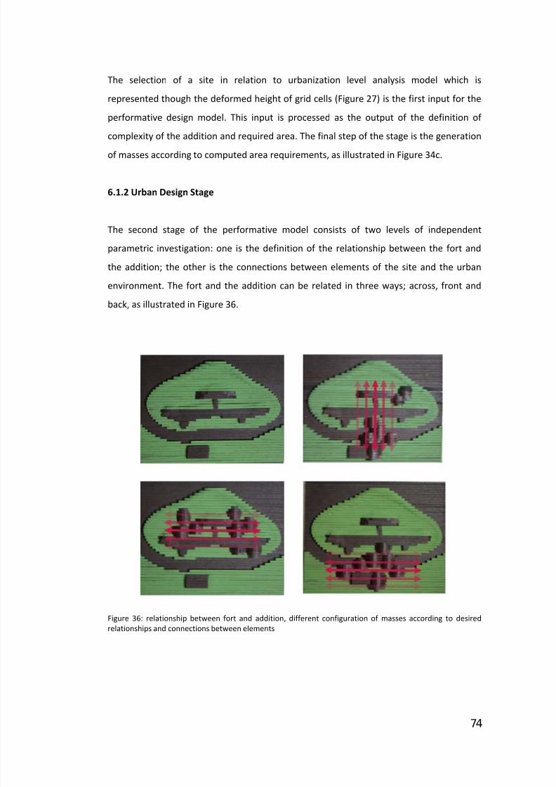
7/29/2019 AMSTERDAM SAVUNMA HATTININ DÖNÜŞTÜRÜLMESİNDE KILAVUZ OLARAK EDİMSEL MİMARLIK
http://slidepdf.com/reader/full/amsterdam-savunma-hattinin-doenuestueruelmesinde-kilavuz-olarak-edimsel 88/121
74
The selection of a site in relation to urbanization level analysis model which is
represented though the deformed height of grid cells (Figure 27) is the first input for the
performative design model. This input is processed as the output of the definition of
complexity of
the
addition
and
required
area.
The
final
step
of
the
stage
is
the
generation
of masses according to computed area requirements, as illustrated in Figure 34c.
6.1.2 Urban Design Stage
The second stage of the performative model consists of two levels of independent
parametric investigation: one is the definition of the relationship between the fort and
the addition; the other is the connections between elements of the site and the urban
environment. The fort and the addition can be related in three ways; across, front and
back, as illustrated in Figure 36.
Figure 36: relationship between fort and addition, different configuration of masses according to desired
relationships and connections between elements
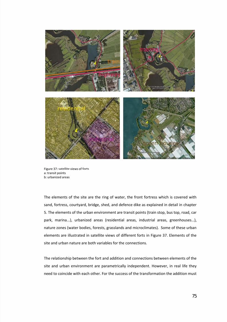
7/29/2019 AMSTERDAM SAVUNMA HATTININ DÖNÜŞTÜRÜLMESİNDE KILAVUZ OLARAK EDİMSEL MİMARLIK
http://slidepdf.com/reader/full/amsterdam-savunma-hattinin-doenuestueruelmesinde-kilavuz-olarak-edimsel 89/121
75
Figure 37:
satellite
views
of
forts
a: transit points b: urbanized areas
The elements of the site are the ring of water, the front fortress which is covered with
sand, fortress, courtyard, bridge, shed, and defence dike as explained in detail in chapter
5. The elements of the urban environment are transit points (train stop, bus top, road, car
park, marina...), urbanized areas (residential areas, industrial areas, greenhouses…),
nature zones
(water
bodies,
forests,
grasslands
and
microclimates).
Some
of
these
urban
elements are illustrated in satellite views of different forts in Figure 37. Elements of the
site and urban nature are both variables for the connections.
The relationship between the fort and addition and connections between elements of the
site and urban environment are parametrically independent. However, in real life they
need to coincide with each other. For the success of the transformation the addition must

7/29/2019 AMSTERDAM SAVUNMA HATTININ DÖNÜŞTÜRÜLMESİNDE KILAVUZ OLARAK EDİMSEL MİMARLIK
http://slidepdf.com/reader/full/amsterdam-savunma-hattinin-doenuestueruelmesinde-kilavuz-olarak-edimsel 90/121
76
provide the needed connections between elements and desired relationship to the fort.
Definitions in levels 1 and 2 act as attractors for the masses. As seen in Figure 36, the
masses generated in the first stage of the performative model are translated according to
the definitions
in
the
two
levels
of
the
model
in
this
stage.
Different
configurations
of
the
needed volumes are created as an output of this stage.
This stage of the performative model enables generation of designs having different
relationships to the original structure. Dissimilar architectural points of views are created
regarding the conservation of forts. The production of digital and physical models (in the
final stage of the model) allows the quantitative and qualitative analyse of the different
configurations. Due to this, the performative model promises success for the
conservation of this UNESCO heritage site.
6.1.3 Building Design Stage
Two independent parametric models have been defined for the building level stage. First
model is to compute catenary arches; and the second one is to compute sunlight angles
according to time and date.
6.1.3.1 Computing Catenary Arches
A parametric model is structured for the definition of catenary arches based on their
equation and structural properties described above in section 5.4.1. First step for the
parameterization is to translate the interdependent variables (a, x and y) into
architectural properties. In an arch, the parameters that define a space are span and
height
of
the
arch.
Bearing
the
graph
of
catenary
arch
(Figure
29b)
in
mind,
these
parameters of an architectural arch corresponds to distance between maximum and
minimum values in x axis and minimum value in the y axis. Therefore, the first input for
the parametric model for a catenary arch is assigning “two points” for maximum and
minimum values in x axis to control the position of supports. Then, the “pole position”
controls the minimum value in the y axis, which is chain length. The input named as
“steps” is the number of points that are computed according to the catenary equation.
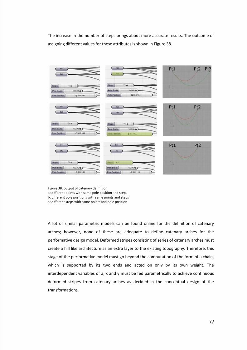
7/29/2019 AMSTERDAM SAVUNMA HATTININ DÖNÜŞTÜRÜLMESİNDE KILAVUZ OLARAK EDİMSEL MİMARLIK
http://slidepdf.com/reader/full/amsterdam-savunma-hattinin-doenuestueruelmesinde-kilavuz-olarak-edimsel 91/121
77
The increase in the number of steps brings about more accurate results. The outcome of
assigning different values for these attributes is shown in Figure 38.
Figure 38: output of catenary definition a: different points with same pole position and steps b: different pole positions with same points and steps a: different steps with same points and pole position
A lot of similar parametric models can be found online for the definition of catenary
arches; however, none of these are adequate to define catenary arches for the
performative design model. Deformed stripes consisting of series of catenary arches must
create a hill like architecture as an extra layer to the existing topography. Therefore, this
stage of the performative model must go beyond the computation of the form of a chain,
which is supported by its two ends and acted on only by its own weight. The
interdependent variables of a, x and y must be fed parametrically to achieve continuous
deformed stripes from catenary arches as decided in the conceptual design of the
transformations.
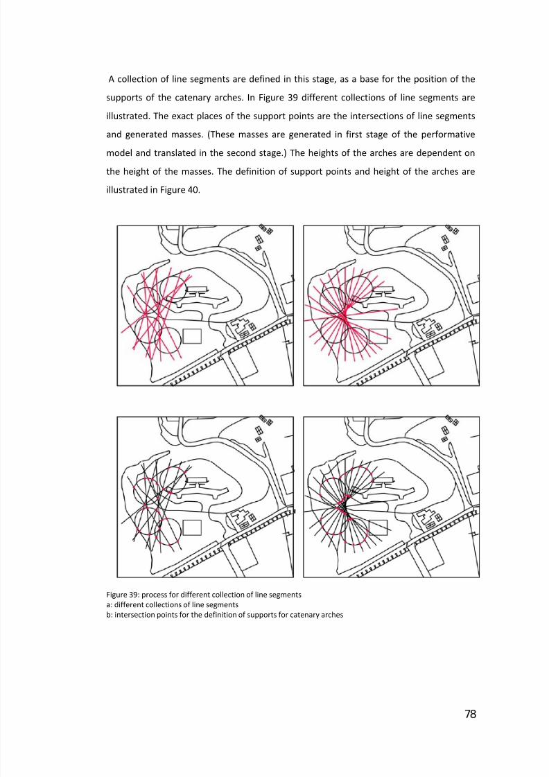
7/29/2019 AMSTERDAM SAVUNMA HATTININ DÖNÜŞTÜRÜLMESİNDE KILAVUZ OLARAK EDİMSEL MİMARLIK
http://slidepdf.com/reader/full/amsterdam-savunma-hattinin-doenuestueruelmesinde-kilavuz-olarak-edimsel 92/121
78
A collection of line segments are defined in this stage, as a base for the position of the
supports of the catenary arches. In Figure 39 different collections of line segments are
illustrated. The exact places of the support points are the intersections of line segments
and generated
masses.
(These
masses
are
generated
in
first
stage
of
the
performative
model and translated in the second stage.) The heights of the arches are dependent on
the height of the masses. The definition of support points and height of the arches are
illustrated in Figure 40.
Figure 39: process for different collection of line segments a: different collections of line segments b: intersection points for the definition of supports for catenary arches
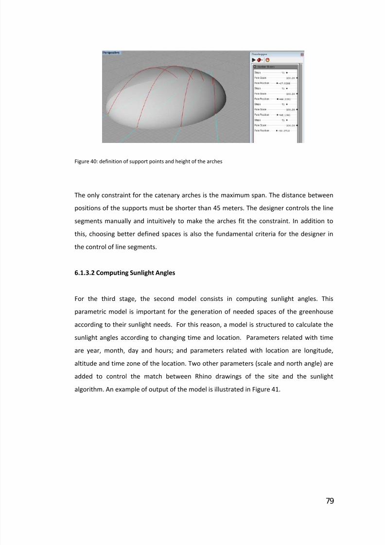
7/29/2019 AMSTERDAM SAVUNMA HATTININ DÖNÜŞTÜRÜLMESİNDE KILAVUZ OLARAK EDİMSEL MİMARLIK
http://slidepdf.com/reader/full/amsterdam-savunma-hattinin-doenuestueruelmesinde-kilavuz-olarak-edimsel 93/121
79
Figure 40: definition of support points and height of the arches
The only constraint for the catenary arches is the maximum span. The distance between
positions of the supports must be shorter than 45 meters. The designer controls the line
segments manually and intuitively to make the arches fit the constraint. In addition to
this, choosing better defined spaces is also the fundamental criteria for the designer in
the control of line segments.
6.1.3.2 Computing Sunlight Angles
For the third stage, the second model consists in computing sunlight angles. This
parametric model is important for the generation of needed spaces of the greenhouse
according to their sunlight needs. For this reason, a model is structured to calculate the
sunlight angles according to changing time and location. Parameters related with time
are year, month, day and hours; and parameters related with location are longitude,
altitude and time zone of the location. Two other parameters (scale and north angle) are
added to control the match between Rhino drawings of the site and the sunlight
algorithm. An example of output of the model is illustrated in Figure 41.

7/29/2019 AMSTERDAM SAVUNMA HATTININ DÖNÜŞTÜRÜLMESİNDE KILAVUZ OLARAK EDİMSEL MİMARLIK
http://slidepdf.com/reader/full/amsterdam-savunma-hattinin-doenuestueruelmesinde-kilavuz-olarak-edimsel 94/121
80
Figure 41: output of the model positioning of the sun through a year
The VB script used for the model is based on the program developed by the University of
Oregon Solar Radiation Monitoring Laboratory (University of Oregon 2011). The
Grasshopper® model used for computing sunlight angles are used in reference to the
studies of the “ateliernGai” which is an experimental design and research studio in the
department of Architecture at Rensselaer Polytechnic Institute (Atelier nGai 2011).
The computed sunlight angles are not used only for analysis. Along with the catenary
arches, they are the generative factor of the form of the addition for the fortress. The
output vectors of this model are matched with the categorization of plants according to
their sunlight needs in chapter 5.4.2. The locations of matches define the voids of the
form that lets sunlight inside, and the catenary arches define the solid parts of the form
which works
as
a structural
system.
In chapters 6.2 and 6.3 the results of different relationships these two models (catenary
arches and sunlight angles) are discussed under the headings of “Instances Set One” and
“Instances Set Two”.
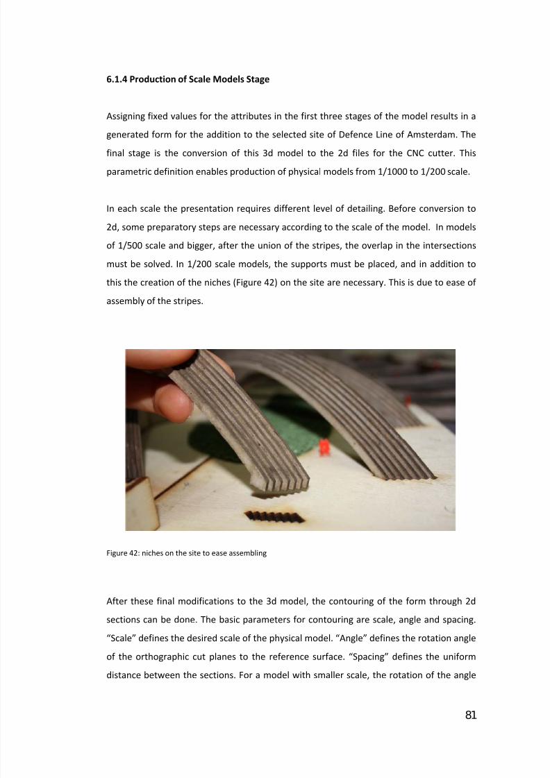
7/29/2019 AMSTERDAM SAVUNMA HATTININ DÖNÜŞTÜRÜLMESİNDE KILAVUZ OLARAK EDİMSEL MİMARLIK
http://slidepdf.com/reader/full/amsterdam-savunma-hattinin-doenuestueruelmesinde-kilavuz-olarak-edimsel 95/121
81
6.1.4 Production of Scale Models Stage
Assigning fixed values for the attributes in the first three stages of the model results in a
generated form
for
the
addition
to
the
selected
site
of
Defence
Line
of
Amsterdam.
The
final stage is the conversion of this 3d model to the 2d files for the CNC cutter. This
parametric definition enables production of physical models from 1/1000 to 1/200 scale.
In each scale the presentation requires different level of detailing. Before conversion to
2d, some preparatory steps are necessary according to the scale of the model. In models
of 1/500 scale and bigger, after the union of the stripes, the overlap in the intersections
must be solved. In 1/200 scale models, the supports must be placed, and in addition to
this the creation of the niches (Figure 42) on the site are necessary. This is due to ease of
assembly of the stripes.
Figure 42: niches on the site to ease assembling
After these final modifications to the 3d model, the contouring of the form through 2d
sections can be done. The basic parameters for contouring are scale, angle and spacing.
“Scale” defines the desired scale of the physical model. “Angle” defines the rotation angle
of the orthographic cut planes to the reference surface. “Spacing” defines the uniform
distance between the sections. For a model with smaller scale, the rotation of the angle

7/29/2019 AMSTERDAM SAVUNMA HATTININ DÖNÜŞTÜRÜLMESİNDE KILAVUZ OLARAK EDİMSEL MİMARLIK
http://slidepdf.com/reader/full/amsterdam-savunma-hattinin-doenuestueruelmesinde-kilavuz-olarak-edimsel 96/121
82
plane has a single value. For larger scales, where the representation of the stripes is more
visible, the attributes for the parameter “angle” are multiple. The contouring for the each
stripe must consist of the sections that are parallel to the stripe. Therefore, the rotation
angle of
the
orthographic
cut
planes
must
be
perpendicular
to
the
stripes.
In
addition
to
these, the model also offers an automated layout to organize the generated sections for
fabrication including labels. Some examples of the results are illustrated in Figure 43.
Production of scale models does not have to be the last stage of the performative model.
1/1000 scale is proper to visualize the results of previous stages as seen in Figures 36 and
43. On the other hand, 1/500 and especially 1/200 scales are proper for investigating
compatibility with the surroundings and relationship with existing elements of the site. If
the results are not favoured, the designer can go to the parameterization stage to change
rules, the relationships between rules and parameters of the attributes. This topic will be
discussed in detail through two examples (instances set one and instances set two)
below.
Figure 43: process for different collection of line segments a: 1/1000 model b: 1/500 and 1/200 model

7/29/2019 AMSTERDAM SAVUNMA HATTININ DÖNÜŞTÜRÜLMESİNDE KILAVUZ OLARAK EDİMSEL MİMARLIK
http://slidepdf.com/reader/full/amsterdam-savunma-hattinin-doenuestueruelmesinde-kilavuz-olarak-edimsel 97/121
83
6.2 “Instances Set One”: Performative Model Elaborated Through the Transformation
of the Fort near Penningsver using Preliminary Dependency Chain
The dependency
chain
of
the
performative
model
is
described
through
parameterization
and articulation. Figure 44 illustrates the preliminary dependency chain. Open ends of the
chain, which act like inputs to the model, are independent variables.
Figure 44: the preliminary dependency chain
7/29/2019 AMSTERDAM SAVUNMA HATTININ DÖNÜŞTÜRÜLMESİNDE KILAVUZ OLARAK EDİMSEL MİMARLIK
http://slidepdf.com/reader/full/amsterdam-savunma-hattinin-doenuestueruelmesinde-kilavuz-olarak-edimsel 98/121
84
In this phase the performative model is ready to generate the first outputs and to assess
the performance of the outputs which will also indicate the success of the performative
model. The outputs which are generated from this dependency chain are named
“instances set
one”.
An
example
output
from
this
set,
referred
as
instance
one
(i1),
is
studied in detail to illustrate how the dependency chain works.
Stage 1:
The first input for the model is the selection of a site. The fort near Penningsver, which
are shown in satellite views in Figure 45, is chosen due to its high urbanization value;
therefore the transformation of the fort requires addition to provide space for cultural,
commercial, educational and recreational functions. As explained in Chapter 6.1 the
conceptual idea for transformation is turning the Defence Line into a greenbelt around
Amsterdam. Accordingly, the fort near Penningsver is turned into a botanical garden.
While defining the program of functions, the primary input is the high urbanization value
of the site. The diagrammatic summary of process for stage one is illustrated in Figure 45.
The fort near Penningsver is transformed into an attraction point as a botanical garden;
moreover it is a transit point and provides connection to other forts in close vicinity by
means of
boat
tours,
biking
and
hiking
trails.
It
is
used
by
two
groups
of
users:
those
that
use the fort as a transfer area that connects the urban elements or within the site, and
visitors who aim to do sight‐seeing and spend time around the fort. Based on these
factors, the program for the botanical garden is as listed in the Table 3. Figure 46 shows
the bubble diagram of program elements and relationships between them.
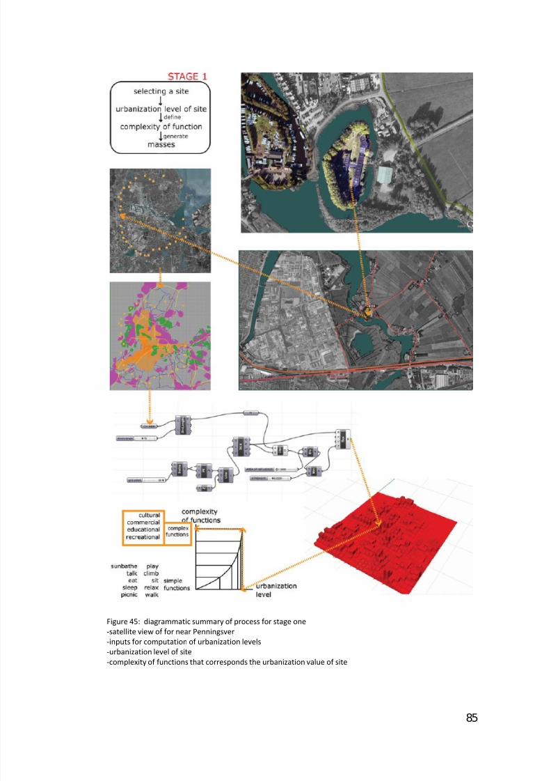
7/29/2019 AMSTERDAM SAVUNMA HATTININ DÖNÜŞTÜRÜLMESİNDE KILAVUZ OLARAK EDİMSEL MİMARLIK
http://slidepdf.com/reader/full/amsterdam-savunma-hattinin-doenuestueruelmesinde-kilavuz-olarak-edimsel 99/121
85
Figure 45: diagrammatic summary of process for stage one
‐satellite view of for near Penningsver ‐inputs for computation of urbanization levels ‐urbanization level of site
‐complexity of functions that corresponds the urbanization value of site
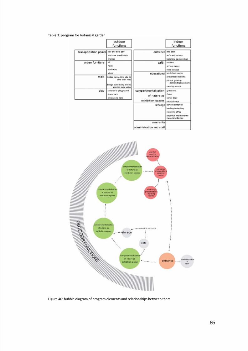
7/29/2019 AMSTERDAM SAVUNMA HATTININ DÖNÜŞTÜRÜLMESİNDE KILAVUZ OLARAK EDİMSEL MİMARLIK
http://slidepdf.com/reader/full/amsterdam-savunma-hattinin-doenuestueruelmesinde-kilavuz-olarak-edimsel 100/121
86
Table 3: program for botanical garden
Figure 46: bubble diagram of program elements and relationships between them

7/29/2019 AMSTERDAM SAVUNMA HATTININ DÖNÜŞTÜRÜLMESİNDE KILAVUZ OLARAK EDİMSEL MİMARLIK
http://slidepdf.com/reader/full/amsterdam-savunma-hattinin-doenuestueruelmesinde-kilavuz-olarak-edimsel 101/121
87
Stage 2:
The relationship between the new building and the fort is initially planned as an indirect
connection. The new building is intended to connect the marina to the car park. This
configuration detached
from
the
fort
creates
a lateral
relationship
with
the
fort
in
plan
while connecting the dike to the marina. The masses that provide adequate space for
these functions are translated according to the definition of the relationship between the
fort and addition and connections between elements of the site and urban environment,
as illustrated in Figure 47.
Stage 3:
The formation of the final form from the mass structure involves the procedures of stage
3, which are explained in detail in Chapter 6.1.3. The two levels of this stage, one for the
structure and one for the voids, are defined as two independent parametric models in the
dependency chain. In other words, the computation of catenary arches and formation of
voids in the structure according to sunlight angle, are defined separately. Figure 48
illustrates the formation of catenary arches in relation to translated masses and a
collection of line segments. Consecutively the voids are created to provide adequate
sunlight for the compartments of the botanical garden, as also illustrated in Figure 49.
Stage 4: The last stage of the performative model enable the production on the 2d files
for the CNC laser cutter to assemble a physical model with 1/500 scale as seen in Figure
48.
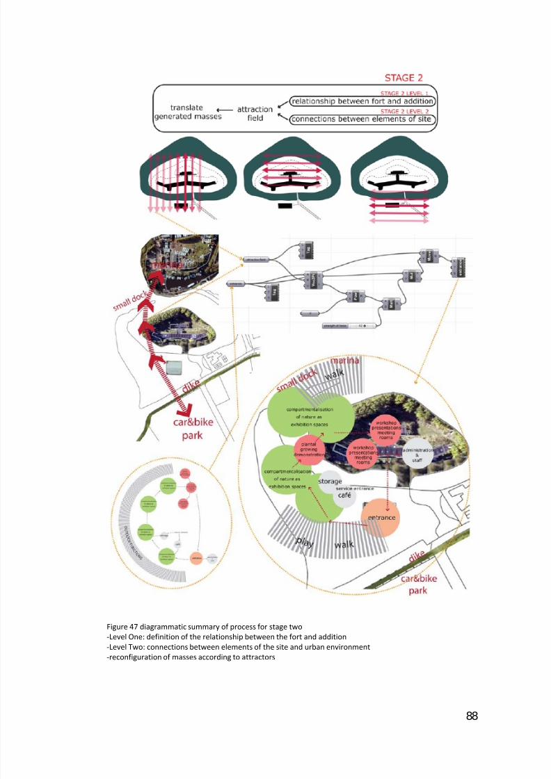
7/29/2019 AMSTERDAM SAVUNMA HATTININ DÖNÜŞTÜRÜLMESİNDE KILAVUZ OLARAK EDİMSEL MİMARLIK
http://slidepdf.com/reader/full/amsterdam-savunma-hattinin-doenuestueruelmesinde-kilavuz-olarak-edimsel 102/121
88
Figure 47 diagrammatic summary of process for stage two
‐Level One: definition of the relationship between the fort and addition
‐Level Two: connections between elements of the site and urban environment ‐reconfiguration of masses according to attractors
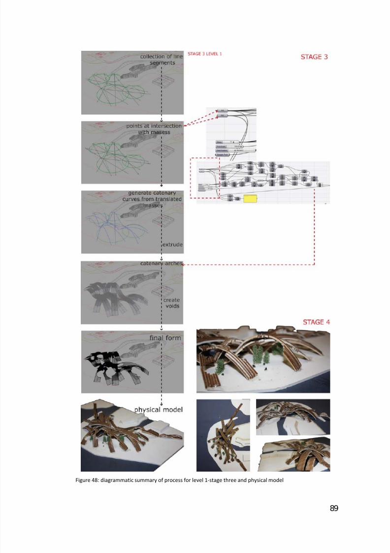
7/29/2019 AMSTERDAM SAVUNMA HATTININ DÖNÜŞTÜRÜLMESİNDE KILAVUZ OLARAK EDİMSEL MİMARLIK
http://slidepdf.com/reader/full/amsterdam-savunma-hattinin-doenuestueruelmesinde-kilavuz-olarak-edimsel 103/121
89
Figure 48: diagrammatic summary of process for level 1‐stage three and physical model

7/29/2019 AMSTERDAM SAVUNMA HATTININ DÖNÜŞTÜRÜLMESİNDE KILAVUZ OLARAK EDİMSEL MİMARLIK
http://slidepdf.com/reader/full/amsterdam-savunma-hattinin-doenuestueruelmesinde-kilavuz-olarak-edimsel 104/121
90
Figure 49: diagrammatic summary of process for level two stage three

7/29/2019 AMSTERDAM SAVUNMA HATTININ DÖNÜŞTÜRÜLMESİNDE KILAVUZ OLARAK EDİMSEL MİMARLIK
http://slidepdf.com/reader/full/amsterdam-savunma-hattinin-doenuestueruelmesinde-kilavuz-olarak-edimsel 105/121
91
Instance one is a preliminary design as an example of a process that results in a form that
does not fulfill the performance criteria. It fails in revitalizing the fort as a new attraction
point for users. The intention was to give minimum impact to the fort by designing a new
fully detached
building;
therefore,
the
new
building
does
not
provide
any
direct
connection to the fort. This attribute does not provide an advantage in the
transformation of the fort; on the other hand it creates a disadvantage by not directing
the users to experience the fort.
Independence of levels one and two in the third stage of the model results in non‐
satisfactory output. The voids computed according to solar nutrition of plants bring about
a weakening of the arches. The catenary arches can no longer be an ideal form due to the
holes for solar gain. The random collections of line segments for the catenary definitions
results in non precise definition of interior spaces. Due to this the intersections of the
arches are not geometrically well‐defined.
The performance of instance one related with the conservation of the site and structural
behaviour requires alterations in the second (urban design) and third (building design)
stages of the performative model.
6.3 “Instances Set Two”: Performative Model Elaborated Through the Transformation of
the Fort near Penningsver using Improved Dependency Chain
The lacking points of instance one have been overcome with two very quick interventions
to the performative model: a parameter change and a dependency change in the
hierarchic structure of the model. The improved version of the dependency chain is
illustrated
in
Figure
50.
The
outputs
which
are
generated
from
this
dependency
chain
are
named generated instances set two. An example output from this set, referred to as
instance two (i2), is studied in detail to illustrate how the dependency chain works.

7/29/2019 AMSTERDAM SAVUNMA HATTININ DÖNÜŞTÜRÜLMESİNDE KILAVUZ OLARAK EDİMSEL MİMARLIK
http://slidepdf.com/reader/full/amsterdam-savunma-hattinin-doenuestueruelmesinde-kilavuz-olarak-edimsel 106/121
92
Figure 50: the improved dependency chain
Stage1:
Instance 2 like instance 1 covers the transformation of the Fort near Penningsver.
Therefore the first stage of performative model is the same as for the previous
dependency chain; which means urbanization level, complexity of functions, potential
users, program for the functions, and generated masses are identical.

7/29/2019 AMSTERDAM SAVUNMA HATTININ DÖNÜŞTÜRÜLMESİNDE KILAVUZ OLARAK EDİMSEL MİMARLIK
http://slidepdf.com/reader/full/amsterdam-savunma-hattinin-doenuestueruelmesinde-kilavuz-olarak-edimsel 107/121
93
Figure 51: diagrammatic summary of process for stage two
‐Level One: definition of the relationship between the fort and addition
‐Level Two: connections between elements of the site and urban environment ‐reconfiguration of masses according to attractors

7/29/2019 AMSTERDAM SAVUNMA HATTININ DÖNÜŞTÜRÜLMESİNDE KILAVUZ OLARAK EDİMSEL MİMARLIK
http://slidepdf.com/reader/full/amsterdam-savunma-hattinin-doenuestueruelmesinde-kilavuz-olarak-edimsel 108/121
94
Stage 2
The only change in the second stage is in the attribution of the parameter that controls
the gradual relationship between the addition and the fort. In Grasshopper® software this
alteration corresponds
to
a change
in
the
attribution
for
the
number
slider
that
control
lateral configuration. The desired connections between urban elements and elements of
the site are the same in the second level of this stage. The diagrammatic summary of the
process for stage two is illustrated in Figure 51.
Stage 3:
The main difference of the improved dependency chain is in the hierarchical structure of
the two levels in the third stage of the design. The collection of line segment which define
the support points for the catenary arches is not an independent value anymore. In plan,
they are generated as perpendicular line segments to the computed sun rays, as
illustrated in Figure 52. In section, the process of generating 3d arches from 2d catenary
curves is not done with basic extrusions in y and z directions. The catenary curves are
turned into 3d arches by extrusions parallel to the computed sun rays. The diagrammatic
summary of process for stage three is illustrated in Figure 53 and 54.
These alterations
in
the
hierarchic
structure
of
performative
model
are
achieved
by
defining new dependencies between the outputs of level 2 and inputs of level 1 in the
third stage of design. In Grasshopper®, these dependency changes can be done very
easily.
Stage 4:
This stage, aiming at the production of a physical model uses the same dependencies as
instance
one.
However
there
are
some
parameter
changes,
such
as
scale.
A
smaller
scale
(1/200) is preferred in order to show more detail in the model. Assembling the model
from CNC laser cut pieces is shown in Figure 55.
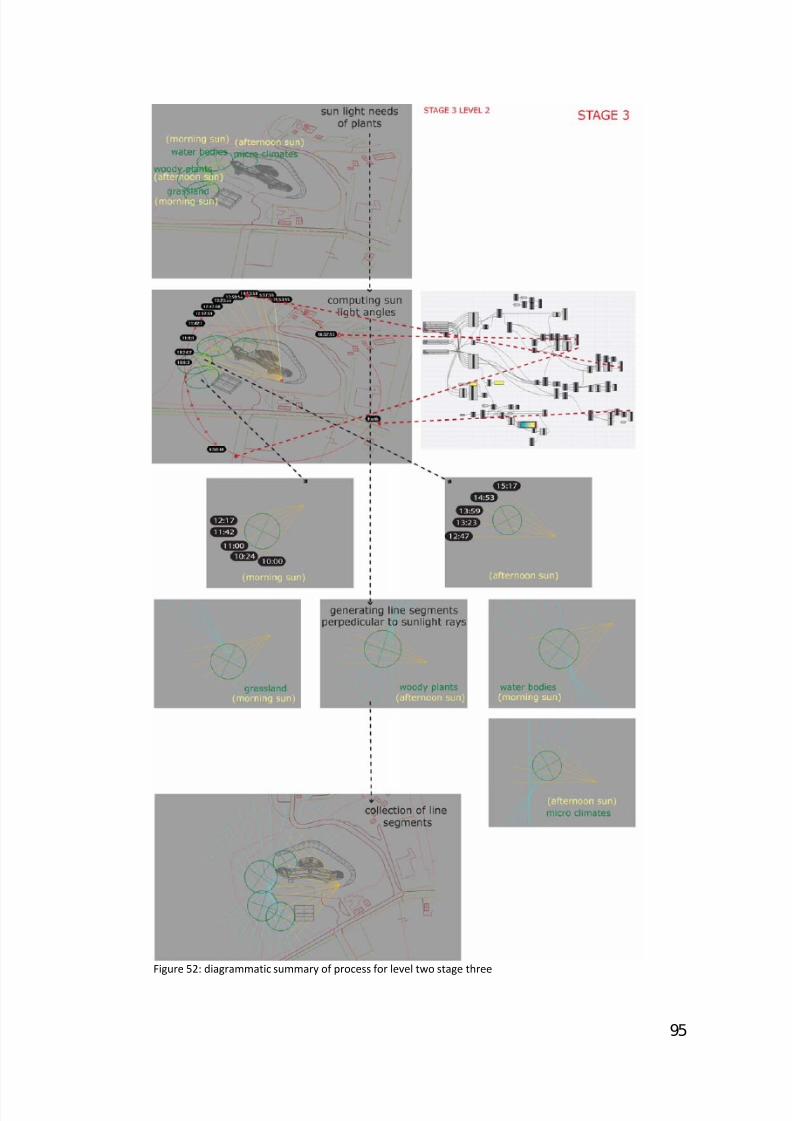
7/29/2019 AMSTERDAM SAVUNMA HATTININ DÖNÜŞTÜRÜLMESİNDE KILAVUZ OLARAK EDİMSEL MİMARLIK
http://slidepdf.com/reader/full/amsterdam-savunma-hattinin-doenuestueruelmesinde-kilavuz-olarak-edimsel 109/121
95
Figure 52: diagrammatic summary of process for level two stage three

7/29/2019 AMSTERDAM SAVUNMA HATTININ DÖNÜŞTÜRÜLMESİNDE KILAVUZ OLARAK EDİMSEL MİMARLIK
http://slidepdf.com/reader/full/amsterdam-savunma-hattinin-doenuestueruelmesinde-kilavuz-olarak-edimsel 110/121
96
Figure 53: diagrammatic summary of process for level 1‐stage three and physical model
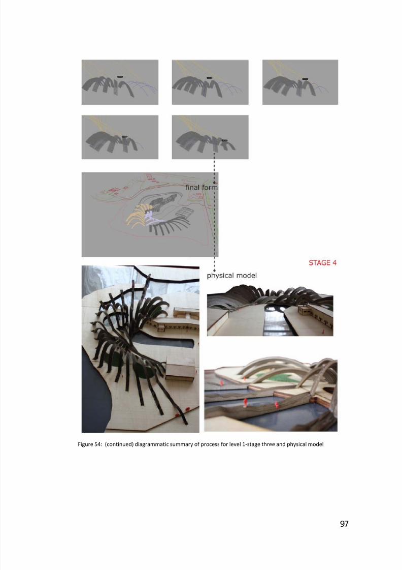
7/29/2019 AMSTERDAM SAVUNMA HATTININ DÖNÜŞTÜRÜLMESİNDE KILAVUZ OLARAK EDİMSEL MİMARLIK
http://slidepdf.com/reader/full/amsterdam-savunma-hattinin-doenuestueruelmesinde-kilavuz-olarak-edimsel 111/121
97
Figure 54: (continued) diagrammatic summary of process for level 1‐stage three and physical model

7/29/2019 AMSTERDAM SAVUNMA HATTININ DÖNÜŞTÜRÜLMESİNDE KILAVUZ OLARAK EDİMSEL MİMARLIK
http://slidepdf.com/reader/full/amsterdam-savunma-hattinin-doenuestueruelmesinde-kilavuz-olarak-edimsel 112/121
98
Figure 55: assembling of pieces of the physical model
7/29/2019 AMSTERDAM SAVUNMA HATTININ DÖNÜŞTÜRÜLMESİNDE KILAVUZ OLARAK EDİMSEL MİMARLIK
http://slidepdf.com/reader/full/amsterdam-savunma-hattinin-doenuestueruelmesinde-kilavuz-olarak-edimsel 113/121
99
CHAPTER 7
CONCLUSION
Performative architecture is not a way of devising a set of practical solutions to a
set of largely practical problems. It is a “meta‐narrative” with universal aims that
are dependent on particular performance‐related aspects of each project.
Determining the different performance aspects in a particular project and
reconciling often conflicting performance goals in a creative and effective way are
some of
the
key
challenges
in
this
approach
to
architecture.
(Kolarevic
2005).
This definition of Kolarevic from the book “Performative Architecture Beyond
Instrumentality” for performative architecture triggered the writing of this thesis, in order
to prove that the developing technologies in the CAM/CAD can respond to the “social
dimension of architecture, beyond general references to a shiny bendy new world.”
(Hagan 2008). Accordingly, within the scope of this thesis “performative architecture” is
used as
a paradigm
of
architecture
which
emphasizes
the
shift
from
building
appearance
to process of formation based on pre‐determined performances. In consequence of the
research (categorization of digital models, classifying different approaches towards
performative architecture, and exemplification of those) conducted, the content of
performative architecture is developed as described below.
Performative architecture defines the architectural object by how it performs (capability
of affecting, transforming and doing). It uses digital generation and modification to search
for alternatives where results are analyzed both qualitatively and quantitatively.
Performative architecture describes the process through which culture, technology and
architecture become interrelated to form a complex field of relations to produce new and
powerful effects.

7/29/2019 AMSTERDAM SAVUNMA HATTININ DÖNÜŞTÜRÜLMESİNDE KILAVUZ OLARAK EDİMSEL MİMARLIK
http://slidepdf.com/reader/full/amsterdam-savunma-hattinin-doenuestueruelmesinde-kilavuz-olarak-edimsel 114/121
100
These definitions of performative architecture are used as a guideline for the
transformation of the Defence Line of Amsterdam. They illustrate the emergent effects of
performative architecture in the topics listed below:
‐combining
developing
technologies
with
cultural
heritage;
‐ using capabilities of affecting, transforming and doing to define additions to the forts (an
element of the cultural heritage);
‐ disclosing functionality and reasoning of a building through the form;
‐ automatically generating different design alternatives for different sites;
‐ enabling quantitative and qualitative analysis through digital and physical models;
‐ producing creative and effective design solutions;
‐ producing new effects that transform culture.
Subsequently defining the outline for the transformation of the Defence Line of
Amsterdam, the research done about digital tools showed that performative approach to
design requires yet to be made digital tools that can provide dynamic process of
formation/generation based on specific performative aspects of design. There are many
digital analytical tools that can help designer asses certain performative aspects of their
projects after an initial design is formed. None of those commercially available tools
provide dynamic
generative
capabilities
for
conceptual
explorations
in
architectural
design. Consequently, instead of describing the architectural object as a conventional
design process, a parametric definition for the transformation of Defence Line of
Amsterdam is structured, called ‘performative design model’. This specific computational
model is structured to provide the generative capabilities for particular performance‐
related aspects of the transformation.
Performative
model
is
introduced
in
4
stages
(regional
design,
urban
design,
building
design, and the production of scale models) which are parallel to the stages of a
conventional design process; therefore it provides design support from conceptual stage
until production of scale prototypes. The production of digital and physical models allows
the quantitative and qualitative analyses of alternative instances.
Performative model is a network consisting of parametric models for those stages of
design that have dependency relationships with each other. The designer is capable of
7/29/2019 AMSTERDAM SAVUNMA HATTININ DÖNÜŞTÜRÜLMESİNDE KILAVUZ OLARAK EDİMSEL MİMARLIK
http://slidepdf.com/reader/full/amsterdam-savunma-hattinin-doenuestueruelmesinde-kilavuz-olarak-edimsel 115/121
101
controlling the parameters and the dependencies of the network. He can change the
rules, the relationships between the rules and parameters of the attributes until he
reaches a satisfactory output. Generally hierarchical nature of the parametric models has
little flexibility
in
changes
of
dependency
chain
once
a model
has
been
created.
On
the
other hand performative model offers great flexibility in the control of dependency
relationships through the medium of Grasshopper®.
Performative model is convenient to create designs within a predefined language but
with dissimilar architectural points of view regarding the conservation of forts. It enables
generation of designs with different relationships with the original structure.
Performative model has a rule based nature; nevertheless designer is not only tool maker,
but also he is the decision maker through every stage of the model. This feature of the
performative model makes possible the creation of different architectural concepts from
the same tool.
The model is able to generate an infinite number of alternative design solutions, but this
potential becomes useless if it is not associated with meaningful control, categorization
and selection processes. Performative model is convenient within this scope since the
designer is
the
decision
maker
in
every
stage
of
the
design,
where
stages
are
defined
as
modules corresponding different performances related to design. An advantage of
dividing a complex system into smaller modules lies in the ease of the intervention to the
rules and parameters. For instance, the second stage of the model is composed of
performance modules related with connections of elements and conservation of site,
therefore alterations of parameters and relations within this stage correspond to
generation of instances with dissimilar behaviours related with these performances. This
feature of
the
performative
model
related
with
control
and
categorization
of
instances
is
used for generating and grouping processes of instances such as set one and two.
Besides all the advantages, the process modelling such complex relationships
computationally is time consuming compared to a design process that uses conventional
design methods. The model is encoded in Grasshopper® through some already existing
commands that the software offers and some additional VbScript for specific purposes. In
some steps using Rhino commands requires less time than writing scripts. Due to time

7/29/2019 AMSTERDAM SAVUNMA HATTININ DÖNÜŞTÜRÜLMESİNDE KILAVUZ OLARAK EDİMSEL MİMARLIK
http://slidepdf.com/reader/full/amsterdam-savunma-hattinin-doenuestueruelmesinde-kilavuz-olarak-edimsel 116/121
102
limit for generating a design solution for graduation project in few steps Rhino commands
are used manually during the formation of instance one and two. These few manually
executed steps do not spoil the parametric nature of the performative model since they
also follow
computational
logic
and
can
be
computable.
For
creation
of
two
instances
they save time, however to compute more outputs they must be translated into scripts.
Only in this way performative model can reach its goal of generating different design
alternatives.
The performative design model proposed in this study has uses beyond generating
alternatives for one site. The transformation of the Defence Line of Amsterdam involves
the transformation of 42 forts, which show similar characteristics but also some
disparities. Due to the fact that the location of the forts is different, they require different
transformations. The performative design model is structured to explore different design
solution spaces for 42 different forts. Due to the wide range of possible use, the
disadvantage of the time spent in implementing the model is offset.
Initially, performative model is structured specifically to represent the complexity of
architectural design problem of transforming the Defence Line of Amsterdam. The final
hierarchic structure
with
flexible
relationships
promises
overall
usage
to
represent
other
architectural problems. The model can be utilized for other design problems in two ways:
using the whole model or using single modules/stages such as: computation of
urbanization levels, defining relationships with site, generating attraction points for
masses, formation, catenary arches, computing sunlight rays, generating 2d drawings
form a three dimensional form. For instance the parametric model for computing
urbanization levels for sites of each for is also beneficial for the site analysis for further
design
problems.
This
is
due
to
variety
of
parameters
and
inputs
that
model
offers.
Another possible use for the performative model is in the transformation of other historic
artefact that shows resemblance to the Defence Line of Amsterdam. For instance in
Portugal, along the coastline of Cascais there is a series of forts. These forts were built in
the 14th century for military proposes against the attacks from sea (Moreira, 1986).
Cascais is in the maritime entrance of Lisbon; therefore the configuration of forts around
the coastline of Cascais (as illustrated in the satellite view in Figure 57) is structured for

7/29/2019 AMSTERDAM SAVUNMA HATTININ DÖNÜŞTÜRÜLMESİNDE KILAVUZ OLARAK EDİMSEL MİMARLIK
http://slidepdf.com/reader/full/amsterdam-savunma-hattinin-doenuestueruelmesinde-kilavuz-olarak-edimsel 117/121
103
the defence of Lisbon. Contemporarily these forts are no more used for military function;
therefore they require transformation and conservation to host new functions. Some
photos of the recent situation of the forts are illustrated in Figure 56. (Ícones de Portugal
2011). Beside
having
an
original
military
function
and
being
in
relation
with
water,
they
also show resemblance to Dutch Defence Line with their relationship with train line and
roads. Performative model structured for Dutch Defence Line is promising for its usability
in the transformation of the forts along Cascais coastline.
Figure 56: photos of the forts from the Cascais coastline
Figure 57: satellite view of the fort along the coast of Cascais

7/29/2019 AMSTERDAM SAVUNMA HATTININ DÖNÜŞTÜRÜLMESİNDE KILAVUZ OLARAK EDİMSEL MİMARLIK
http://slidepdf.com/reader/full/amsterdam-savunma-hattinin-doenuestueruelmesinde-kilavuz-olarak-edimsel 118/121
104
The performative model structured within the scope of this thesis is only dependent on
particular performance‐related aspects of the transformation of the Defence Line of
Amsterdam. A model which aims to address a wider range of design problems must cover
more categories of building performance; therefore as a further research we proposed to
add new modules to the model to cover a wider range of performances.

7/29/2019 AMSTERDAM SAVUNMA HATTININ DÖNÜŞTÜRÜLMESİNDE KILAVUZ OLARAK EDİMSEL MİMARLIK
http://slidepdf.com/reader/full/amsterdam-savunma-hattinin-doenuestueruelmesinde-kilavuz-olarak-edimsel 119/121
105
REFERENCES
Bosma,
K.
(1994).
“De
stelling
van
Amsterdam;
cultuurhistorie
en landschapsarchitectuur” , Rotterdam : Stichting Locus, 1994.
Cross, N. and Maver, T. M. (1973). “Computer Aids for Design Participation” . Architectural Design. 53: 274.
Edler, J. (2005). “Communicative Display Skin For Buildings: BIX At The Kunsthaus Graz.“ Performative Architecture Beyond Instrumentality . B. Kolarevic and A. M. Malkawi, Spon
Press: 149‐160.
Greg, L. (1999). “Animate Form” , Princeton Architectural Press.
Hagan, S. (2008). “Digitalia ‐ Architecture and the Digital, the Environmental and the
Avant‐Garde” , Routledge.
Menges, A. (2007). “Computational Morphogenesis ‐ Integral Form Generation and
Materialization Processes” . 3rd Int’l ASCAAD Conference on Em‘body’ing Virtual
Architecture:
725‐
744.
Julian (1999). Scarre, Chris. ed. “The Seventy Wonders of the Ancient world The Great Monuments and How they were Built” . Thames & Hudson. pp. 185–186.
Kalay, Y. E. (1992). “Evaluating and Predicting Design Performance” . Y. E. Kalay, Wiley
Kalay, Y. E. (1999). "Performance‐based design." Automation in Construction 8: 395–409.
Kloft, H. (2005). “Non‐standard structural Design for Non‐Standard Architecture”. Performative Architecture Beyond Instrumentality . B. Kolarevic and A. M. Malkawi, Spon
Press: 135‐148.
Kolarevic, B. (2003). “Architecture in the Digital Age: Design and Manufacturing” . S. Press: 11‐28.

7/29/2019 AMSTERDAM SAVUNMA HATTININ DÖNÜŞTÜRÜLMESİNDE KILAVUZ OLARAK EDİMSEL MİMARLIK
http://slidepdf.com/reader/full/amsterdam-savunma-hattinin-doenuestueruelmesinde-kilavuz-olarak-edimsel 120/121
106
Kolarevic, B. (2005). “Computing the Performative.” Performative Architecture Beyond
Instrumentality . B. Kolarevic and A. M. Malkawi, Spon Press: 193‐202.
Kolarevic, B. (2005). “Towards the Performative in Architecture.” Performative
Architecture Beyond
Instrumentality .
B.
Kolarevic
and
A.
M.
Malkawi,
Spon
Press:
203
‐
213.
Leatherbarrow, D. (2005). “Architecture's Unscripted Performance.” Performative
Architecture Beyond Instrumentality . B. Kolarevic and A. M. Malkawi, Spon Press: 5‐19.
Mahdavi, A., Mathew, P. et al. (1997). "Bi‐directional computational design support in
the SEMPER environment." Automation in Construction 6: 353‐373.
Malkawi, A. M. (2005). “Performance Simulation: Research and Tools.” Performative
Architecture Beyond Instrumentality . B. Kolarevic and A. M. Malkawi, Spon Press: 86‐95.
McClearly, P. (2005). “Performance (and Performers): In Search of Direction (and a Director).” Performative Architecture Beyond Instrumentality . B. Kolarevic and A. M. Malkawi, Spon Press: 215‐224.
Menges, A., Hensel, M. (2008). “Inclusive Performance: Efficiency Versus Effectiveness ‐
Towards a Morpho
‐Ecological
Approach
for
Design.”
Architectural
Design.
78:
54
‐63.
MOREIRA, R. “A arquitectura militar.” História da Arte em Portugal ‐ O Maneirismo (v. 7). Lisboa: 1986.7
Oxman, R. (2006). "Theory and design in the first digital age." Design Studies 27: 229‐265.
Oxman, R. (2009). "Performative design: a performance‐based model of digital
architectural design."
Environment
and
Planning
B:
Planning
and
Design
36:
1026
‐1037.
Oxman, R., R. Hammer, et al. “Performative Design in Architecture Employment of Virtual Prototyping as a Simulation Environment in Design Generation.” eCAADe 25: 227‐234.
Pedreschi, R. (2008). “Form, Force and Structure: A Brief History.” Architectural Design. 78: 12‐19.

7/29/2019 AMSTERDAM SAVUNMA HATTININ DÖNÜŞTÜRÜLMESİNDE KILAVUZ OLARAK EDİMSEL MİMARLIK
http://slidepdf.com/reader/full/amsterdam-savunma-hattinin-doenuestueruelmesinde-kilavuz-olarak-edimsel 121/121
Preiser, W. F., Vischer J. C. (2005). “Assessing Building Performance”, Elsevier .
Turrin, M., A. Kilian, et al. (2009). "Digital Design Exploration of Structural Morphologies Integrating Adaptable Models ‐ A design process based on parametric modeling." PUM:
800‐814.
Sheaa, K., Aishb, R. et al. (2005). "Towards integrated performance‐driven generative design tools." Automation in Construction 14: 253‐264.
Vesters, P., Baas, H., et al. (2003). “De stelling van Amsterdam : harnas voor de hoofdstad
/ onder red”, Utrecht : Matrijs, 2003.
Atelier
nGai
(2011),
“http://www.tedngai.net/experiments/incident‐solar
‐current
‐
time.html” Last accessed 10 January 2011
Future Systems (2011), “http://www.future‐systems.com/architecture/architecture_19.html#” Last accessed 10
January 2011
Ícones de Portugal (2011), “http://mjfs.wordpress.com/category/fortalezas/” Last accessed 10 January 2011
Orambra (2010), “http://www.orambra.com/” Last accessed 10 January 2011
Rijksoverheid (2011), http://www.rijksoverheid.nl/onderwerpen/randstad/randstad‐2040
L t d 10 J 2011