Embed Size (px)
Citation preview
8/8/2019 An 3402
http://slidepdf.com/reader/full/an-3402 1/12
Freescale SemiconductorApplication Note
Document Number: AN3402Rev. 0, 04/2007
Contents
© Freescale Semiconductor, Inc., 2007. All rights reserved.
1 Introduction
This application note explains how to implement the
infrared light (IR) RC-5 decoder software module on
Freescale’s microcontroller unit (MCU) MC9RS08KA2.
The MCU KA2 can be used with a standard IR receiver
as the remote control module with five output pins for
common use. One standard GPIO pin is connected to astandard IR receiver. The other free pins of the MCU are
used as standard GPIO pins. Although, you can choose
which pins are used as the IIC bus pins, the PTA0 and
PTA1 pins are used in this example.
2 RC-5 Coding Summary
Several standards exist for IR wireless communication
for remote control applications. The widely used coding
scheme is RC-5 from Philips. This coding type is briefly
described in the following section. Figure 1 shows the
RC-5 frame format.
1 Introduction . . . . . . . . . . . . . . . . . . . . . . . . . . . . . . . . . . . 1
2 RC-5 Coding Summary . . . . . . . . . . . . . . . . . . . . . . . . . . 1
2.1 Bit Transfer . . . . . . . . . . . . . . . . . . . . . . . . . . . . . . . 2
2.2 Standard RC-5 Codes . . . . . . . . . . . . . . . . . . . . . . . 2
3 Application Description . . . . . . . . . . . . . . . . . . . . . . . . . . 4
4 RC-5 software for MCU. . . . . . . . . . . . . . . . . . . . . . . . . . 4
5 Conclusion. . . . . . . . . . . . . . . . . . . . . . . . . . . . . . . . . . . . 5
Implemening the Infrared RC-5Decoder on MC9RS08KA2by: Stanislav Arendarik
Application Engineer
Roznov, Czech Republic
8/8/2019 An 3402
http://slidepdf.com/reader/full/an-3402 2/12
Implemening the Infrared RC-5 Decoder on MC9RS08KA2, Rev. 0
RC-5 Coding Summary
Freescale Semiconductor2
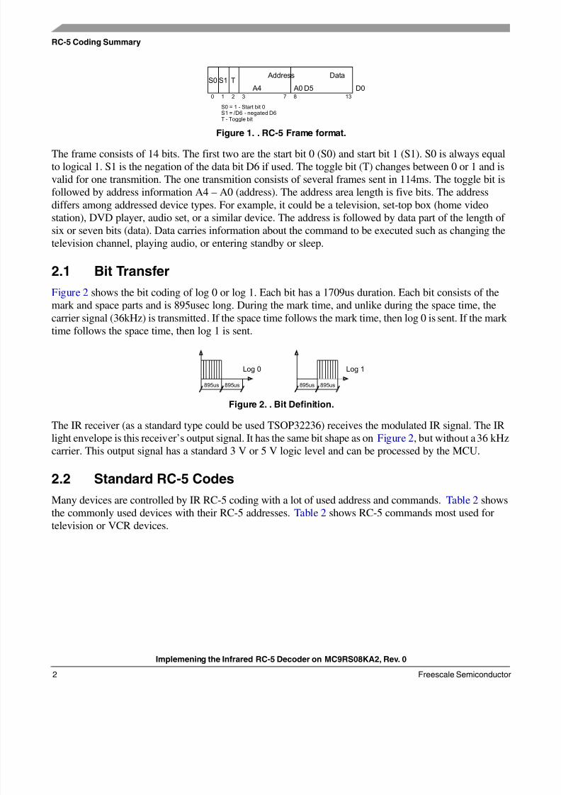
Figure 1. . RC-5 Frame format.
The frame consists of 14 bits. The first two are the start bit 0 (S0) and start bit 1 (S1). S0 is always equal
to logical 1. S1 is the negation of the data bit D6 if used. The toggle bit (T) changes between 0 or 1 and is
valid for one transmition. The one transmition consists of several frames sent in 114ms. The toggle bit is
followed by address information A4 – A0 (address). The address area length is five bits. The address
differs among addressed device types. For example, it could be a television, set-top box (home video
station), DVD player, audio set, or a similar device. The address is followed by data part of the length of
six or seven bits (data). Data carries information about the command to be executed such as changing the
television channel, playing audio, or entering standby or sleep.
2.1 Bit TransferFigure 2 shows the bit coding of log 0 or log 1. Each bit has a 1709us duration. Each bit consists of the
mark and space parts and is 895usec long. During the mark time, and unlike during the space time, the
carrier signal (36kHz) is transmitted. If the space time follows the mark time, then log 0 is sent. If the mark
time follows the space time, then log 1 is sent.
Figure 2. . Bit Definition.
The IR receiver (as a standard type could be used TSOP32236) receives the modulated IR signal. The IR
light envelope is this receiver’s output signal. It has the same bit shape as on Figure 2, but without a 36 kHz
carrier. This output signal has a standard 3 V or 5 V logic level and can be processed by the MCU.
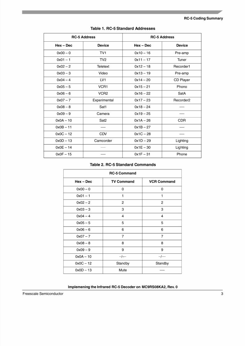
2.2 Standard RC-5 Codes
Many devices are controlled by IR RC-5 coding with a lot of used address and commands. Table 2 shows
the commonly used devices with their RC-5 addresses. Table 2 shows RC-5 commands most used for
television or VCR devices.
S0 S1 T
A4 A0 D5 D0
Address Data
S0 = 1 - Start bit 0S1 = /D6 - negated D6T - Toggle bit
0 1 2 3 7 8 13
895us 895us 895us895us
Log 0 Log 1
8/8/2019 An 3402
http://slidepdf.com/reader/full/an-3402 3/12
RC-5 Coding Summary
Implemening the Infrared RC-5 Decoder on MC9RS08KA2, Rev. 0
Freescale Semiconductor 3
Table 1. RC-5 Standard Addresses
RC-5 Address RC-5 Address
Hex – Dec Device Hex – Dec Device
0x00 – 0 TV1 0x10 – 16 Pre-amp
0x01 – 1 TV2 0x11 – 17 Tuner
0x02 – 2 Teletext 0x12 – 18 Recorder1
0x03 – 3 Video 0x13 – 19 Pre-amp
0x04 – 4 LV1 0x14 – 20 CD Player
0x05 – 5 VCR1 0x15 – 21 Phono
0x06 – 6 VCR2 0x16 – 22 SatA
0x07 – 7 Experimental 0x17 – 23 Recorder2
0x08 – 8 Sat1 0x18 – 24 —
0x09 – 9 Camera 0x19 – 25 —
0x0A – 10 Sat2 0x1A – 26 CDR
0x0B – 11 — 0x1B – 27 —
0x0C – 12 CDV 0x1C – 28 —
0x0D – 13 Camcorder 0x1D – 29 Lighting
0x0E – 14 — 0x1E – 30 Lighting
0x0F – 15 — 0x1F – 31 Phone
Table 2. RC-5 Standard Commands
RC-5 Command
Hex – Dec TV Command VCR Command
0x00 – 0 0 0
0x01 – 1 1 1
0x02 – 2 2 2
0x03 – 3 3 3
0x04 – 4 4 4
0x05 – 5 5 5
0x06 – 6 6 6
0x07 – 7 7 7
0x08 – 8 8 8
0x09 – 9 9 9
0x0A – 10 –/–– –/––
0x0C – 12 Standby Standby
0x0D – 13 Mute —
8/8/2019 An 3402
http://slidepdf.com/reader/full/an-3402 4/12
Implemening the Infrared RC-5 Decoder on MC9RS08KA2, Rev. 0
Application Description
Freescale Semiconductor4
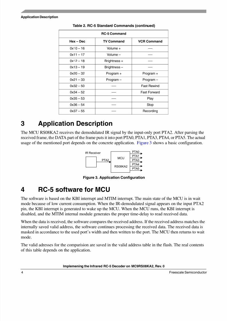
3 Application Description
The MCU RS08KA2 receives the demodulated IR signal by the input-only port PTA2. After parsing the
received frame, the DATA part of the frame puts it into port PTA0, PTA1, PTA3, PTA4, or PTA5. The actual
usage of the mentioned port depends on the concrete application. Figure 3 shows a basic configuration.
Figure 3. Application Configuration
4 RC-5 software for MCU
The software is based on the KBI interrupt and MTIM interrupt. The main state of the MCU is in wait
mode because of low current consumption. When the IR-demodulated signal appears on the input PTA2
pin, the KBI interrupt is generated to wake up the MCU. When the MCU runs, the KBI interrupt is
disabled, and the MTIM internal module generates the proper time-delay to read received data.
When the data is received, the software compares the received address. If the received address matches the
internally saved valid address, the software continues processing the received data. The received data is
masked in accordance to the used port’s width and then written to the port. The MCU then returns to wait
mode.
The valid adresses for the comparision are saved in the valid address table in the flash. The real contents
of this table depends on the application.
0x10 – 16 Volume + —
0x11 – 17 Volume – —0x12 – 18 Brightness + —
0x13 – 19 Brightness – —
0x20 – 32 Program + Program +
0x21 – 33 Program – Program –
0x32 – 50 — Fast Rewind
0x34 – 52 — Fast Forward
0x35 – 53 — Play
0x36 – 54 — Stop
0x37 – 55 — Recording
Table 2. RC-5 Standard Commands (continued)
RC-5 Command
Hex – Dec TV Command VCR Command
IR Receiver PTA0
PTA1
PTA3
PTA4
PTA5
MCU
RS08KA2
PTA2
8/8/2019 An 3402
http://slidepdf.com/reader/full/an-3402 5/12
Conclusion
Implemening the Infrared RC-5 Decoder on MC9RS08KA2, Rev. 0
Freescale Semiconductor 5
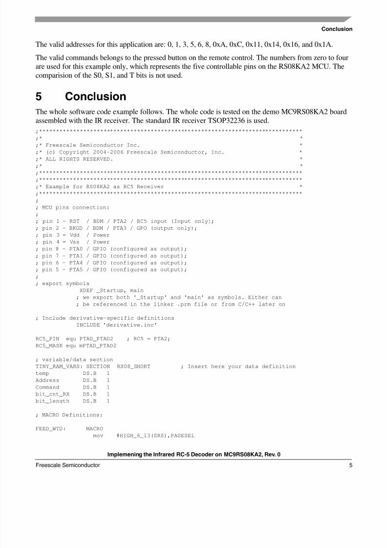
The valid addresses for this application are: 0, 1, 3, 5, 6, 8, 0xA, 0xC, 0x11, 0x14, 0x16, and 0x1A.
The valid commands belongs to the pressed button on the remote control. The numbers from zero to four
are used for this example only, which represents the five controllable pins on the RS08KA2 MCU. The
comparision of the S0, S1, and T bits is not used.
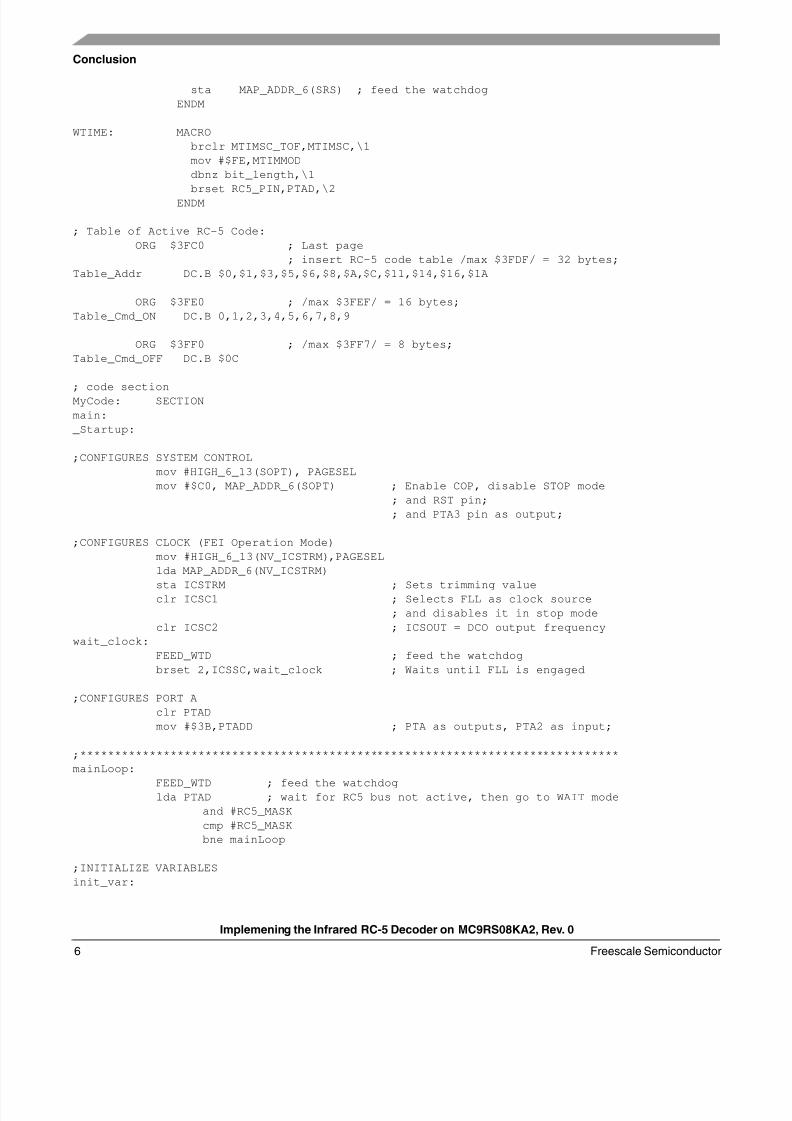
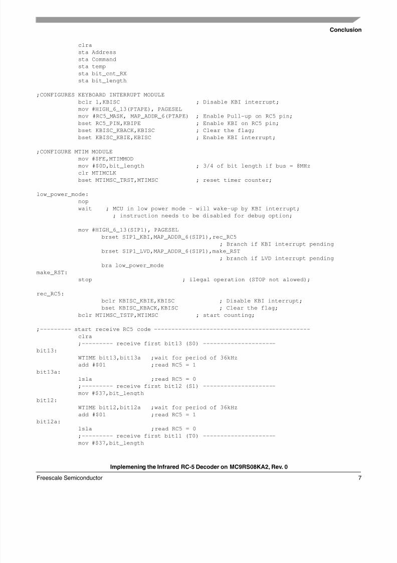
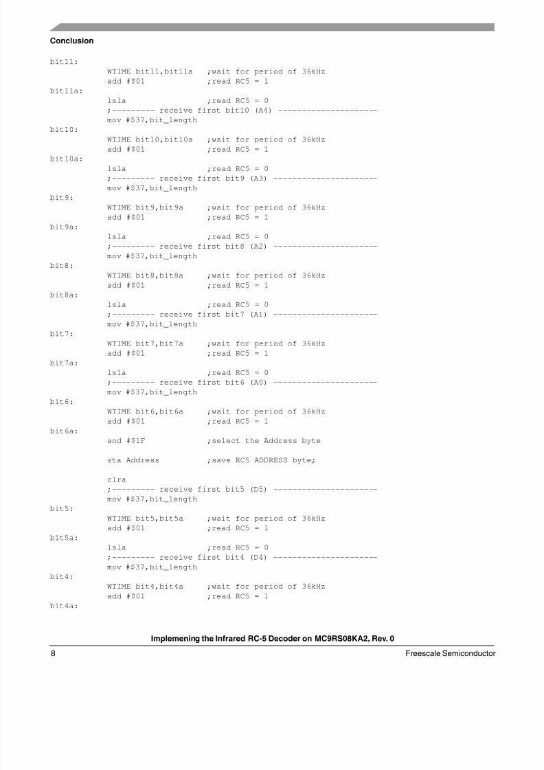
5 ConclusionThe whole software code example follows. The whole code is tested on the demo MC9RS08KA2 board
assembled with the IR receiver. The standard IR receiver TSOP32236 is used.
;******************************************************************************
;* *
;* Freescale Semiconductor Inc. *
;* (c) Copyright 2004-2006 Freescale Semiconductor, Inc. *
;* ALL RIGHTS RESERVED. *
;* *
;******************************************************************************
;******************************************************************************
;* Example for RS08KA2 as RC5 Receiver *
;******************************************************************************
;
; MCU pins connection:
;
; pin 1 - RST / BDM / PTA2 / RC5 input (Input only);
; pin 2 - BKGD / BDM / PTA3 / GPO (output only);
; pin 3 = Vdd / Power
; pin 4 = Vss / Power
; pin 8 - PTA0 / GPIO (configured as output);
; pin 7 - PTA1 / GPIO (configured as output);
; pin 6 - PTA4 / GPIO (configured as output);
; pin 5 - PTA5 / GPIO (configured as output);
;
; export symbols
XDEF _Startup, main
; we export both '_Startup' and 'main' as symbols. Either can
; be referenced in the linker .prm file or from C/C++ later on
; Include derivative-specific definitions
INCLUDE 'derivative.inc'
RC5_PIN equ PTAD_PTAD2 ; RC5 = PTA2;
RC5_MASK equ mPTAD_PTAD2
; variable/data section
TINY_RAM_VARS: SECTION RS08_SHORT ; Insert here your data definition
temp DS.B 1
Address DS.B 1
Command DS.B 1
bit_cnt_RX DS.B 1
bit_length DS.B 1
; MACRO Definitions:
FEED_WTD: MACRO
mov #HIGH_6_13(SRS),PAGESEL
8/8/2019 An 3402
http://slidepdf.com/reader/full/an-3402 6/12
Implemening the Infrared RC-5 Decoder on MC9RS08KA2, Rev. 0
Conclusion
Freescale Semiconductor6
sta MAP_ADDR_6(SRS) ; feed the watchdog
ENDM
WTIME: MACRO
brclr MTIMSC_TOF,MTIMSC,\1
mov #$FE,MTIMMOD
dbnz bit_length,\1
brset RC5_PIN,PTAD,\2
ENDM
; Table of Active RC-5 Code:
ORG $3FC0 ; Last page
; insert RC-5 code table /max $3FDF/ = 32 bytes;
Table_Addr DC.B $0,$1,$3,$5,$6,$8,$A,$C,$11,$14,$16,$1A
ORG $3FE0 ; /max $3FEF/ = 16 bytes;
Table_Cmd_ON DC.B 0,1,2,3,4,5,6,7,8,9
ORG $3FF0 ; /max $3FF7/ = 8 bytes;
Table_Cmd_OFF DC.B $0C
; code section
MyCode: SECTION
main:
_Startup:
;CONFIGURES SYSTEM CONTROL
mov #HIGH_6_13(SOPT), PAGESEL
mov #$C0, MAP_ADDR_6(SOPT) ; Enable COP, disable STOP mode
; and RST pin;
; and PTA3 pin as output;
;CONFIGURES CLOCK (FEI Operation Mode)
mov #HIGH_6_13(NV_ICSTRM),PAGESEL
lda MAP_ADDR_6(NV_ICSTRM)
sta ICSTRM ; Sets trimming valueclr ICSC1 ; Selects FLL as clock source
; and disables it in stop mode
clr ICSC2 ; ICSOUT = DCO output frequency
wait_clock:
FEED_WTD ; feed the watchdog
brset 2,ICSSC,wait_clock ; Waits until FLL is engaged
;CONFIGURES PORT A
clr PTAD
mov #$3B,PTADD ; PTA as outputs, PTA2 as input;
;******************************************************************************
mainLoop:
FEED_WTD ; feed the watchdoglda PTAD ; wait for RC5 bus not active, then go to WAIT mode
and #RC5_MASK
cmp #RC5_MASK
bne mainLoop
;INITIALIZE VARIABLES
init_var:
8/8/2019 An 3402
http://slidepdf.com/reader/full/an-3402 7/12
Conclusion
Implemening the Infrared RC-5 Decoder on MC9RS08KA2, Rev. 0
Freescale Semiconductor 7
clra
sta Address
sta Command
sta temp
sta bit_cnt_RX
sta bit_length
;CONFIGURES KEYBOARD INTERRUPT MODULE
bclr 1,KBISC ; Disable KBI interrupt;
mov #HIGH_6_13(PTAPE), PAGESEL
mov #RC5_MASK, MAP_ADDR_6(PTAPE) ; Enable Pull-up on RC5 pin;
bset RC5_PIN,KBIPE ; Enable KBI on RC5 pin;
bset KBISC_KBACK,KBISC ; Clear the flag;
bset KBISC_KBIE,KBISC ; Enable KBI interrupt;
;CONFIGURE MTIM MODULE
mov #$FE,MTIMMOD
mov #$0D,bit_length ; 3/4 of bit length if bus = 8MHz
clr MTIMCLK
bset MTIMSC_TRST,MTIMSC ; reset timer counter;
low_power_mode:
nop
wait ; MCU in low power mode - will wake-up by KBI interrupt;
; instruction needs to be disabled for debug option;
mov #HIGH_6_13(SIP1), PAGESEL
brset SIP1_KBI,MAP_ADDR_6(SIP1),rec_RC5
; Branch if KBI interrupt pending
brset SIP1_LVD,MAP_ADDR_6(SIP1),make_RST
; branch if LVD interrupt pending
bra low_power_mode
make_RST:
stop ; ilegal operation (STOP not alowed);
rec_RC5:bclr KBISC_KBIE,KBISC ; Disable KBI interrupt;
bset KBISC_KBACK,KBISC ; Clear the flag;
bclr MTIMSC_TSTP,MTIMSC ; start counting;
;--------- start receive RC5 code ---------------------------------------------
clra
;--------- receive first bit13 (S0) ---------------------
bit13:
WTIME bit13,bit13a ;wait for period of 36kHz
add #$01 ;read RC5 = 1
bit13a:
lsla ;read RC5 = 0
;--------- receive first bit12 (S1) ---------------------
mov #$37,bit_lengthbit12:
WTIME bit12,bit12a ;wait for period of 36kHz
add #$01 ;read RC5 = 1
bit12a:
lsla ;read RC5 = 0
;--------- receive first bit11 (T0) ---------------------
mov #$37,bit_length
8/8/2019 An 3402
http://slidepdf.com/reader/full/an-3402 8/12
Implemening the Infrared RC-5 Decoder on MC9RS08KA2, Rev. 0
Conclusion
Freescale Semiconductor8
bit11:
WTIME bit11,bit11a ;wait for period of 36kHz
add #$01 ;read RC5 = 1
bit11a:
lsla ;read RC5 = 0
;--------- receive first bit10 (A4) ---------------------
mov #$37,bit_length
bit10:
WTIME bit10,bit10a ;wait for period of 36kHz
add #$01 ;read RC5 = 1
bit10a:
lsla ;read RC5 = 0
;--------- receive first bit9 (A3) ----------------------
mov #$37,bit_length
bit9:
WTIME bit9,bit9a ;wait for period of 36kHz
add #$01 ;read RC5 = 1
bit9a:
lsla ;read RC5 = 0
;--------- receive first bit8 (A2) ----------------------
mov #$37,bit_length
bit8:
WTIME bit8,bit8a ;wait for period of 36kHz
add #$01 ;read RC5 = 1
bit8a:
lsla ;read RC5 = 0
;--------- receive first bit7 (A1) ----------------------
mov #$37,bit_length
bit7:
WTIME bit7,bit7a ;wait for period of 36kHz
add #$01 ;read RC5 = 1
bit7a:
lsla ;read RC5 = 0
;--------- receive first bit6 (A0) ----------------------
mov #$37,bit_length
bit6:WTIME bit6,bit6a ;wait for period of 36kHz
add #$01 ;read RC5 = 1
bit6a:
and #$1F ;select the Address byte
sta Address ;save RC5 ADDRESS byte;
clra
;--------- receive first bit5 (D5) ----------------------
mov #$37,bit_length
bit5:
WTIME bit5,bit5a ;wait for period of 36kHz
add #$01 ;read RC5 = 1
bit5a:lsla ;read RC5 = 0
;--------- receive first bit4 (D4) ----------------------
mov #$37,bit_length
bit4:
WTIME bit4,bit4a ;wait for period of 36kHz
add #$01 ;read RC5 = 1
bit4a:
8/8/2019 An 3402
http://slidepdf.com/reader/full/an-3402 9/12
Conclusion
Implemening the Infrared RC-5 Decoder on MC9RS08KA2, Rev. 0
Freescale Semiconductor 9
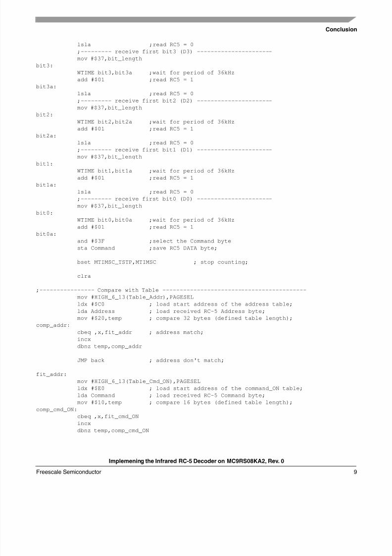
lsla ;read RC5 = 0
;--------- receive first bit3 (D3) ----------------------
mov #$37,bit_length
bit3:
WTIME bit3,bit3a ;wait for period of 36kHz
add #$01 ;read RC5 = 1
bit3a:
lsla ;read RC5 = 0
;--------- receive first bit2 (D2) ----------------------
mov #$37,bit_length
bit2:
WTIME bit2,bit2a ;wait for period of 36kHz
add #$01 ;read RC5 = 1
bit2a:
lsla ;read RC5 = 0
;--------- receive first bit1 (D1) ----------------------
mov #$37,bit_length
bit1:
WTIME bit1,bit1a ;wait for period of 36kHz
add #$01 ;read RC5 = 1
bit1a:
lsla ;read RC5 = 0
;--------- receive first bit0 (D0) ----------------------
mov #$37,bit_length
bit0:
WTIME bit0,bit0a ;wait for period of 36kHz
add #$01 ;read RC5 = 1
bit0a:
and #$3F ;select the Command byte
sta Command ;save RC5 DATA byte;
bset MTIMSC_TSTP,MTIMSC ; stop counting;
clra
;---------------- Compare with Table ------------------------------------------mov #HIGH_6_13(Table_Addr),PAGESEL
ldx #$C0 ; load start address of the address table;
lda Address ; load received RC-5 Address byte;
mov #$20,temp ; compare 32 bytes (defined table length);
comp_addr:
cbeq ,x,fit_addr ; address match;
incx
dbnz temp,comp_addr
JMP back ; address don't match;
fit_addr:
mov #HIGH_6_13(Table_Cmd_ON),PAGESEL
ldx #$E0 ; load start address of the command_ON table;lda Command ; load received RC-5 Command byte;
mov #$10,temp ; compare 16 bytes (defined table length);
comp_cmd_ON:
cbeq ,x,fit_cmd_ON
incx
dbnz temp,comp_cmd_ON
8/8/2019 An 3402
http://slidepdf.com/reader/full/an-3402 10/12
Implemening the Infrared RC-5 Decoder on MC9RS08KA2, Rev. 0
Conclusion
Freescale Semiconductor10
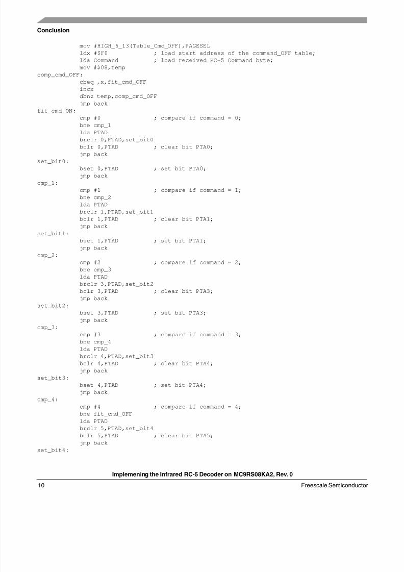
mov #HIGH_6_13(Table_Cmd_OFF),PAGESEL
ldx #$F0 ; load start address of the command_OFF table;
lda Command ; load received RC-5 Command byte;
mov #$08,temp
comp_cmd_OFF:
cbeq ,x,fit_cmd_OFF
incx
dbnz temp,comp_cmd_OFF
jmp back
fit_cmd_ON:
cmp #0 ; compare if command = 0;
bne cmp_1
lda PTAD
brclr 0,PTAD,set_bit0
bclr 0,PTAD ; clear bit PTA0;
jmp back
set_bit0:
bset 0,PTAD ; set bit PTA0;
jmp back
cmp_1:
cmp #1 ; compare if command = 1;
bne cmp_2
lda PTAD
brclr 1,PTAD,set_bit1
bclr 1,PTAD ; clear bit PTA1;
jmp back
set_bit1:
bset 1,PTAD ; set bit PTA1;
jmp back
cmp_2:
cmp #2 ; compare if command = 2;
bne cmp_3
lda PTAD
brclr 3,PTAD,set_bit2
bclr 3,PTAD ; clear bit PTA3;
jmp backset_bit2:
bset 3,PTAD ; set bit PTA3;
jmp back
cmp_3:
cmp #3 ; compare if command = 3;
bne cmp_4
lda PTAD
brclr 4,PTAD,set_bit3
bclr 4,PTAD ; clear bit PTA4;
jmp back
set_bit3:
bset 4,PTAD ; set bit PTA4;
jmp back
cmp_4:cmp #4 ; compare if command = 4;
bne fit_cmd_OFF
lda PTAD
brclr 5,PTAD,set_bit4
bclr 5,PTAD ; clear bit PTA5;
jmp back
set_bit4:
8/8/2019 An 3402
http://slidepdf.com/reader/full/an-3402 11/12
Conclusion
Implemening the Infrared RC-5 Decoder on MC9RS08KA2, Rev. 0
Freescale Semiconductor 11
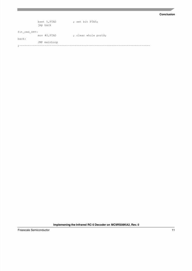
bset 5,PTAD ; set bit PTA5;
jmp back
fit_cmd_OFF:
mov #0,PTAD ; clear whole portA;
back:
JMP mainLoop
;------------------------------------------------------------------------------
8/8/2019 An 3402
http://slidepdf.com/reader/full/an-3402 12/12
Document Number: AN3402Rev. 004/2007
How to Reach Us:
Home Page:www.freescale.com
E-mail:[email protected]
USA/Europe or Locations Not Listed:Freescale SemiconductorTechnical Information Center, CH3701300 N. Alma School RoadChandler, Arizona 85224+1-800-521-6274 or [email protected]
Europe, Middle East, and Africa:Freescale Halbleiter Deutschland GmbHTechnical Information CenterSchatzbogen 781829 Muenchen, Germany+44 1296 380 456 (English)+46 8 52200080 (English)+49 89 92103 559 (German)+33 1 69 35 48 48 (French)[email protected]
Japan:Freescale Semiconductor Japan Ltd.HeadquartersARCO Tower 15F1-8-1, Shimo-Meguro, Meguro-ku,Tokyo 153-0064Japan0120 191014 or +81 3 5437 [email protected]
Asia/Pacific:Freescale Semiconductor Hong Kong Ltd.Technical Information Center2 Dai King StreetTai Po Industrial EstateTai Po, N.T., Hong Kong+800 2666 [email protected]
For Literature Requests Only: Freescale Semiconductor Literature Distribution CenterP.O. Box 5405Denver, Colorado 802171-800-441-2447 or 303-675-2140Fax: [email protected]
Information in this document is provided solely to enable system and software
implementers to use Freescale Semiconductor products. There are no express or
implied copyright licenses granted hereunder to design or fabricate any integrated
circuits or integrated circuits based on the information in this document.
Freescale Semiconductor reserves the right to make changes without further notice to
any products herein. Freescale Semiconductor makes no warranty, representation orguarantee regarding the suitability of its products for any par ticular purpose, nor does
Freescale Semiconductor assume any liability arising out of the application or use of any
product or circuit, and specifically disclaims any and all liability, including without
limitation consequential or incidental damages. “Typical” parameters that may be
provided in Freescale Semiconductor data sheets and/or specifications can and do vary
in different applications and actual performance may vary over time. All operating
parameters, including “Typicals”, must be validated for each customer application by
customer’s technical experts. Freescale Semiconductor does not convey any license
under its patent rights nor the rights of others. Freescale Semiconductor products are
not designed, intended, or authorized for use as components in systems intended for
surgical implant into the body, or other applications intended to support or sustain life,
or for any other application in which the failure of the Freescale Semiconductor product
could create a situation where personal injury or death may occur. Should Buyer
purchase or use Freescale Semiconductor products for any such unintended or
unauthorized application, Buyer shall indemnify and hold Freescale Semiconductor and
its officers, employees, subsidiaries, affiliates, and distributors harmless against all
claims, costs, damages, and expenses, and reasonable attorney fees arising out of,directly or indirectly, any claim of personal injury or death associated with such
unintended or unauthorized use, even if such claim alleges that Freescale
Semiconductor was negligent regarding the design or manufacture of the part.
Freescale™ and the Freescale logo are trademarks of Freescale Semiconductor, Inc.
All other product or service names are the property of their respective owners.
© Freescale Semiconductor, Inc. 2007. All rights reserved.
RoHS-compliant and/or Pb-free versions of Freescale products have the functionality
and electrical characteristics as their non-RoHS-compliant and/or non-Pb-free
counterparts. For further information, see http://www.freescale.com or contact your
Freescale sales representative.
For information on Freescale’s Environmental Products program, go to
http://www.freescale.com/epp .