Embed Size (px)
Citation preview
An ABB SACE Division technical journal
on Modular Devices
1|11
When technology helps tradition 14A happy family story, over four generationsDisconnection is synonymous with safety and savings 24 The subdivision of the electric system into zones Photovoltaics in demand 28Feed-in tariff news
News and interesting facts for informed professionals
Day by DIN
2 Day by DIN 1|11 Day by DIN 1|11
Editorial
Day by DIN 1| 11 •An ABB SACE Division technical journal - Modular Devices • copyright 2011 • Modular Devices Product Management: Emanuele Tosatti • E-mail: [email protected] • Published by: ABB S.p.A. - ABB SACE Division • Design: Winning Associates Printed by: Caleidograf • Any use of texts or images is forbidden without the prior written consent of ABB S.p.A.- ABB SACE Division
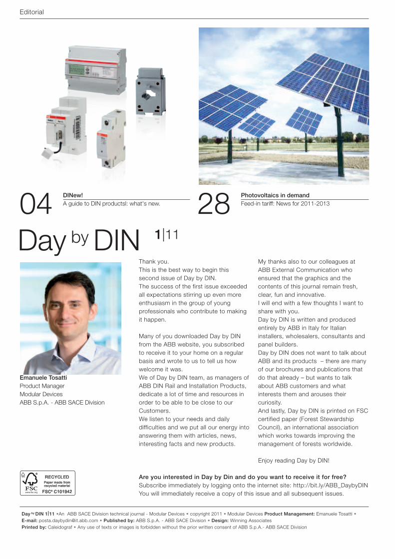
04 28 DINew! A guide to DIN productsl: what's new.
Photovoltaics in demand Feed-in tariff: News for 2011-2013
Thank you.This is the best way to begin this second issue of Day by DIN.The success of the first issue exceeded all expectations stirring up even more enthusiasm in the group of young professionals who contribute to making it happen.
Many of you downloaded Day by DIN from the ABB website, you subscribed to receive it to your home on a regular basis and wrote to us to tell us how welcome it was.We of Day by DIN team, as managers of ABB DIN Rail and Installation Products, dedicate a lot of time and resources in order to be able to be close to our Customers. We listen to your needs and daily difficulties and we put all our energy into answering them with articles, news, interesting facts and new products.
My thanks also to our colleagues at ABB External Communication who ensured that the graphics and the contents of this journal remain fresh, clear, fun and innovative. I will end with a few thoughts I want to share with you.Day by DIN is written and produced entirely by ABB in Italy for Italian installers, wholesalers, consultants and panel builders.Day by DIN does not want to talk about ABB and its products – there are many of our brochures and publications that do that already – but wants to talk about ABB customers and what interests them and arouses their curiosity.And lastly, Day by DIN is printed on FSC certified paper (Forest Stewardship Council), an international association which works towards improving the management of forests worldwide.
Enjoy reading Day by DIN!
Emanuele TosattiProduct ManagerModular DevicesABB S.p.A. - ABB SACE Division
Day by DIN 1|11
Are you interested in Day by Din and do you want to receive it for free?Subscribe immediately by logging onto the internet site: http://bit.ly/ABB_DaybyDINYou will immediately receive a copy of this issue and all subsequent issues.
Day by DIN 1|11 3Day by DIN 1|11
News and facts4 DINew!
A guide to DIN products: what's new 6 In the news
Literature on our latest products8 Top six
Market classification9 On-line training courses 23 Events
Announcement of events in the business
The expert answers7 Letters from the front (panel)
The editor responds 20 Urban legends
Exploding the myths and reconsidering convictions
38 How much does he know The expert answers
39 Did you know that... Lighting management using relays
Case History 14 When technology helps tradition
A happy family story, over four generations
History and surroundings34 The incandescent lamp is phased out
A little bit of history and some interesting facts
Technical10 Dear stand-by, how much you are costing
me… Have you ever asked yourself how much it costs to keep all our appliances on stand-by?
24 Disconnection is synonymous with safety and savings The subdivision of the electric plant into zones28 Photovoltaics in demand
Feed-in tariffs: News for 2011-201340 Seen from within!
The hidden aspect of everyday devices
Time to relax42 The Electrical Network
Amongst alternative energy, new supply tariffs and energy saving
43 DIN Photos
Contents
34
40
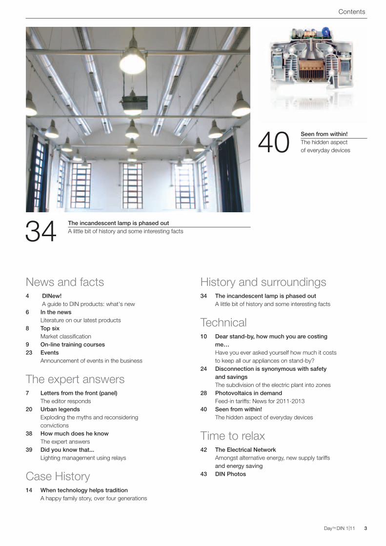
The incandescent lamp is phased outA little bit of history and some interesting facts
Seen from within!The hidden aspect of everyday devices
4 Day by DIN 1|11 Day by DIN 1|11
News and facts
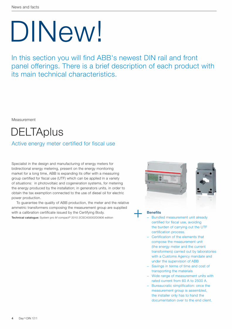
DINew!In this section you will find ABB's newest DIN rail and front panel offerings. There is a brief description of each product with its main technical characteristics.
Specialist in the design and manufacturing of energy meters for bidirectional energy metering, present on the energy monitoring market for a long time, ABB is expanding its offer with a measuring group certified for fiscal use (UTF) which can be applied in a variety of situations: in photovoltaic and cogeneration systems, for metering the energy produced by the installation; in generators units, in order to obtain the tax exemption connected to the use of diesel oil for electric power production. To guarantee the quality of ABB production, the meter and the relative ammetric transformers composing the measurement group are supplied with a calibration certificate issued by the Certifying Body.Technical catalogue: System pro M compact® 2010 2CSC400002D0906 edition
DELTAplusMeasurement
Active energy meter certified for fiscal use
Benefits − Bundled measurement unit already
certified for fiscal use, avoiding the burden of carrying out the UTF certification process.
− Certification of the elements that compose the measurement unit (the energy meter and the current transformers) carried out by laboratories with a Customs Agency mandate and under the supervision of ABB
− Savings in terms of time and cost of transporting the materials
− Wide range of measurement units with rated current from 60 A to 2500 A.
− Bureaucratic simplification: once the measurement group is assembled, the installer only has to hand the documentation over to the end client.
Day by DIN 1|11 5Day by DIN 1|11
News and facts
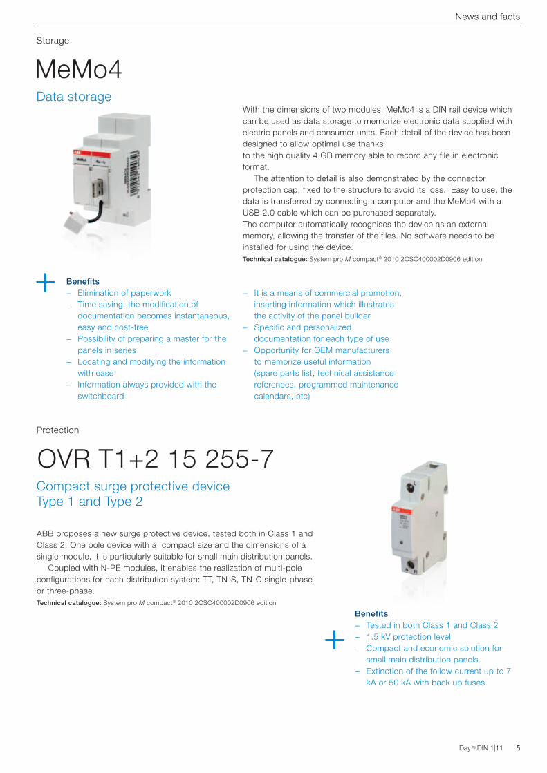
With the dimensions of two modules, MeMo4 is a DIN rail device which can be used as data storage to memorize electronic data supplied with electric panels and consumer units. Each detail of the device has been designed to allow optimal use thanks to the high quality 4 GB memory able to record any file in electronic format. The attention to detail is also demonstrated by the connector protection cap, fixed to the structure to avoid its loss. Easy to use, the data is transferred by connecting a computer and the MeMo4 with a USB 2.0 cable which can be purchased separately. The computer automatically recognises the device as an external memory, allowing the transfer of the files. No software needs to be installed for using the device.Technical catalogue: System pro M compact® 2010 2CSC400002D0906 edition
MeMo4Storage
Benefits − Elimination of paperwork − Time saving: the modification of
documentation becomes instantaneous, easy and cost-free
− Possibility of preparing a master for the panels in series
− Locating and modifying the information with ease
− Information always provided with the switchboard
− It is a means of commercial promotion, inserting information which illustrates the activity of the panel builder
− Specific and personalized documentation for each type of use
− Opportunity for OEM manufacturers to memorize useful information (spare parts list, technical assistance references, programmed maintenance calendars, etc)
Data storage
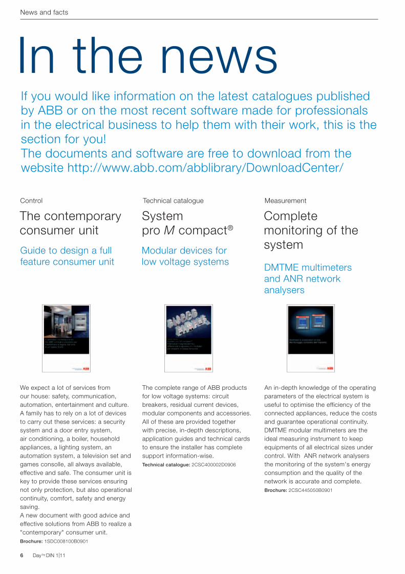
ABB proposes a new surge protective device, tested both in Class 1 and Class 2. One pole device with a compact size and the dimensions of a single module, it is particularly suitable for small main distribution panels. Coupled with N-PE modules, it enables the realization of multi-pole configurations for each distribution system: TT, TN-S, TN-C single-phase or three-phase.Technical catalogue: System pro M compact® 2010 2CSC400002D0906 edition
OVR T1+2 15 255-7Protection
Benefits − Tested in both Class 1 and Class 2 − 1.5 kV protection level − Compact and economic solution for
small main distribution panels − Extinction of the follow current up to 7
kA or 50 kA with back up fuses
Compact surge protective device Type 1 and Type 2
6 Day by DIN 1|11 Day by DIN 1|11
The complete range of ABB products for low voltage systems: circuit breakers, residual current devices, modular components and accessories. All of these are provided together with precise, in-depth descriptions, application guides and technical cards to ensure the installer has complete support information-wise.Technical catalogue: 2CSC400002D0906
System pro M compact®
News and facts
Technical catalogue
An in-depth knowledge of the operating parameters of the electrical system is useful to optimise the efficiency of the connected appliances, reduce the costs and guarantee operational continuity. DMTME modular multimeters are the ideal measuring instrument to keep equipments of all electrical sizes under control. With ANR network analysers the monitoring of the system's energy consumption and the quality of the network is accurate and complete.Brochure: 2CSC445050B0901
Complete monitoring of the system
Measurement
DMTME multimeters and ANR network analysers
Modular devices for low voltage systems
We expect a lot of services from our house: safety, communication, automation, entertainment and culture. A family has to rely on a lot of devices to carry out these services: a security system and a door entry system, air conditioning, a boiler, household appliances, a lighting system, an automation system, a television set and games consolle, all always available, effective and safe. The consumer unit is key to provide these services ensuring not only protection, but also operational continuity, comfort, safety and energy saving. A new document with good advice and effective solutions from ABB to realize a "contemporary" consumer unit.Brochure: 1SDC008100B0901
The contemporary consumer unit
Control
Guide to design a full feature consumer unit
In the newsIf you would like information on the latest catalogues publishedby ABB or on the most recent software made for professionalsin the electrical business to help them with their work, this is thesection for you!The documents and software are free to download from thewebsite http://www.abb.com/abblibrary/DownloadCenter/
Day by DIN 1|11 7Day by DIN 1|11
The specialists respond
Letters from the front (panel)The editor respondsOn this page, professionals can interact with ABB, always with a view to a continuous updating of their own professional capacities. Your letters and FAQ to ABB regarding the DIN rail products and front panels find their own space in this column.
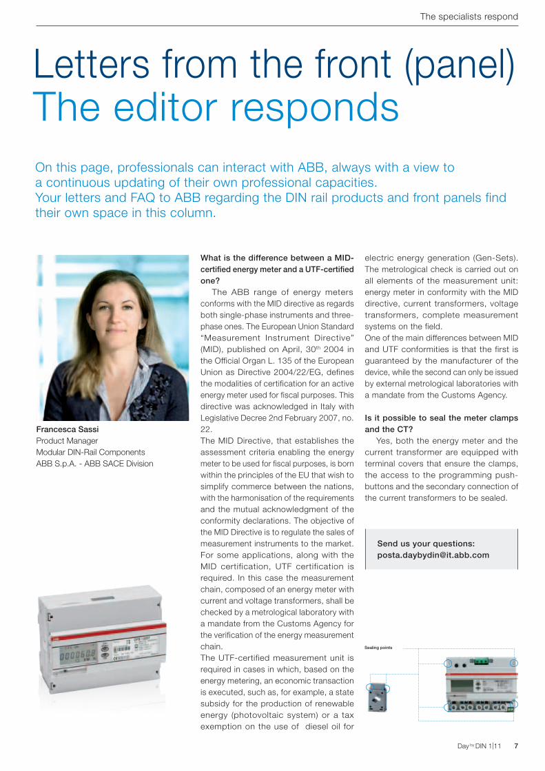
What is the difference between a MID-certified energy meter and a UTF-certified one? The ABB range of energy meters conforms with the MID directive as regards both single-phase instruments and three-phase ones. The European Union Standard “Measurement Instrument Directive” (MID), published on April, 30th 2004 in the Official Organ L. 135 of the European Union as Directive 2004/22/EG, defines the modalities of certification for an active energy meter used for fiscal purposes. This directive was acknowledged in Italy with Legislative Decree 2nd February 2007, no. 22.The MID Directive, that establishes the assessment criteria enabling the energy meter to be used for fiscal purposes, is born within the principles of the EU that wish to simplify commerce between the nations, with the harmonisation of the requirements and the mutual acknowledgment of the conformity declarations. The objective of the MID Directive is to regulate the sales of measurement instruments to the market.For some applications, along with the MID certification, UTF certification is required. In this case the measurement chain, composed of an energy meter with current and voltage transformers, shall be checked by a metrological laboratory with a mandate from the Customs Agency for the verification of the energy measurement chain. The UTF-certified measurement unit is required in cases in which, based on the energy metering, an economic transaction is executed, such as, for example, a state subsidy for the production of renewable energy (photovoltaic system) or a tax exemption on the use of diesel oil for
electric energy generation (Gen-Sets). The metrological check is carried out on all elements of the measurement unit: energy meter in conformity with the MID directive, current transformers, voltage transformers, complete measurement systems on the field.One of the main differences between MID and UTF conformities is that the first is guaranteed by the manufacturer of the device, while the second can only be issued by external metrological laboratories with a mandate from the Customs Agency.
Is it possible to seal the meter clamps and the CT? Yes, both the energy meter and the current transformer are equipped with terminal covers that ensure the clamps, the access to the programming push-buttons and the secondary connection of the current transformers to be sealed.
Send us your questions:[email protected]
Francesca SassiProduct ManagerModular DIN-Rail ComponentsABB S.p.A. - ABB SACE Division
Sealing points
8 Day by DIN 1|11 Day by DIN 1|11
Top sixSix solutions to ensure the system operational continuity for more comfort in your home and higher productivity in the workplace.
News and facts
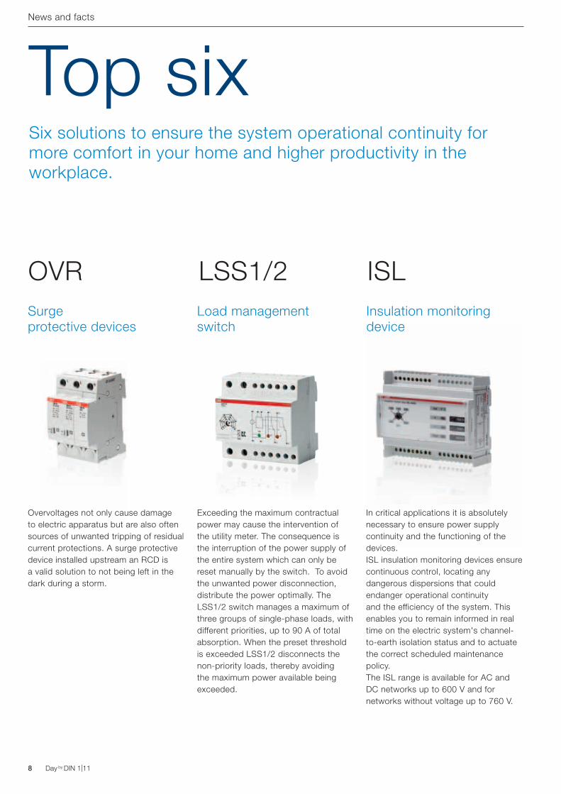
Exceeding the maximum contractual power may cause the intervention of the utility meter. The consequence is the interruption of the power supply of the entire system which can only be reset manually by the switch. To avoid the unwanted power disconnection, distribute the power optimally. The LSS1/2 switch manages a maximum of three groups of single-phase loads, with different priorities, up to 90 A of total absorption. When the preset threshold is exceeded LSS1/2 disconnects the non-priority loads, thereby avoiding the maximum power available being exceeded.
LSS1/2
In critical applications it is absolutely necessary to ensure power supply continuity and the functioning of the devices. ISL insulation monitoring devices ensure continuous control, locating any dangerous dispersions that could endanger operational continuity and the efficiency of the system. This enables you to remain informed in real time on the electric system's channel-to-earth isolation status and to actuate the correct scheduled maintenance policy. The ISL range is available for AC and DC networks up to 600 V and for networks without voltage up to 760 V.
ISLInsulation monitoring device
Load management switch
Overvoltages not only cause damage to electric apparatus but are also often sources of unwanted tripping of residual current protections. A surge protective device installed upstream an RCD is a valid solution to not being left in the dark during a storm.
OVRSurge protective devices
On-line training courses
Throughout 2011 ABB is organizing technical seminars on-line.Sitting comfortably in front of the computer, you can take part in a webinar, actively participating in the seminar and with the possibility to ask to the speaker questions live just as if you were participating in a course held in a lecture hall!A new method which allows you to learn in a "virtual class".
We have already programmed the seminars on the new CAT and DOC software on the following dates:
− 5th and 25th February − 15th March − 9th May − 13th June
To receive the training newsletter and register for the next Webinars, send an email to the address: [email protected]
Formazione Tecnica 2011 per i professionisti del mondo elettrico
Catalogue: 1SDC007005B0909
Day by DIN 1|11 9Day by DIN 1|11
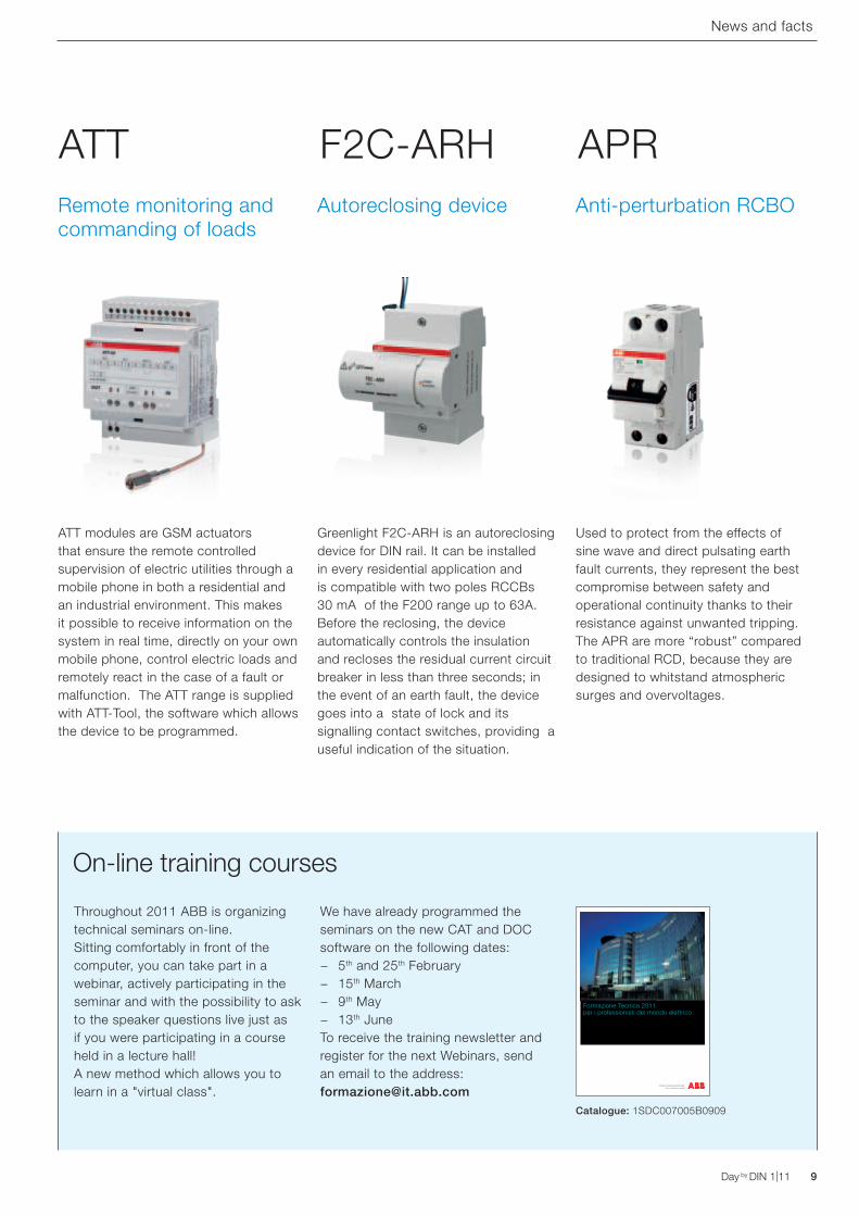
Greenlight F2C-ARH is an autoreclosing device for DIN rail. It can be installed in every residential application and is compatible with two poles RCCBs 30 mA of the F200 range up to 63A. Before the reclosing, the device automatically controls the insulation and recloses the residual current circuit breaker in less than three seconds; in the event of an earth fault, the device goes into a state of lock and its signalling contact switches, providing a useful indication of the situation.
Used to protect from the effects of sine wave and direct pulsating earth fault currents, they represent the best compromise between safety and operational continuity thanks to their resistance against unwanted tripping. The APR are more “robust” compared to traditional RCD, because they are designed to whitstand atmospheric surges and overvoltages.
F2C-ARH APRAutoreclosing device Anti-perturbation RCBO
ATT modules are GSM actuators that ensure the remote controlled supervision of electric utilities through a mobile phone in both a residential and an industrial environment. This makes it possible to receive information on the system in real time, directly on your own mobile phone, control electric loads and remotely react in the case of a fault or malfunction. The ATT range is supplied with ATT-Tool, the software which allows the device to be programmed.
ATTRemote monitoring and commanding of loads
News and facts
10 Day by DIN 1|11 Day by DIN 1|11
Technical
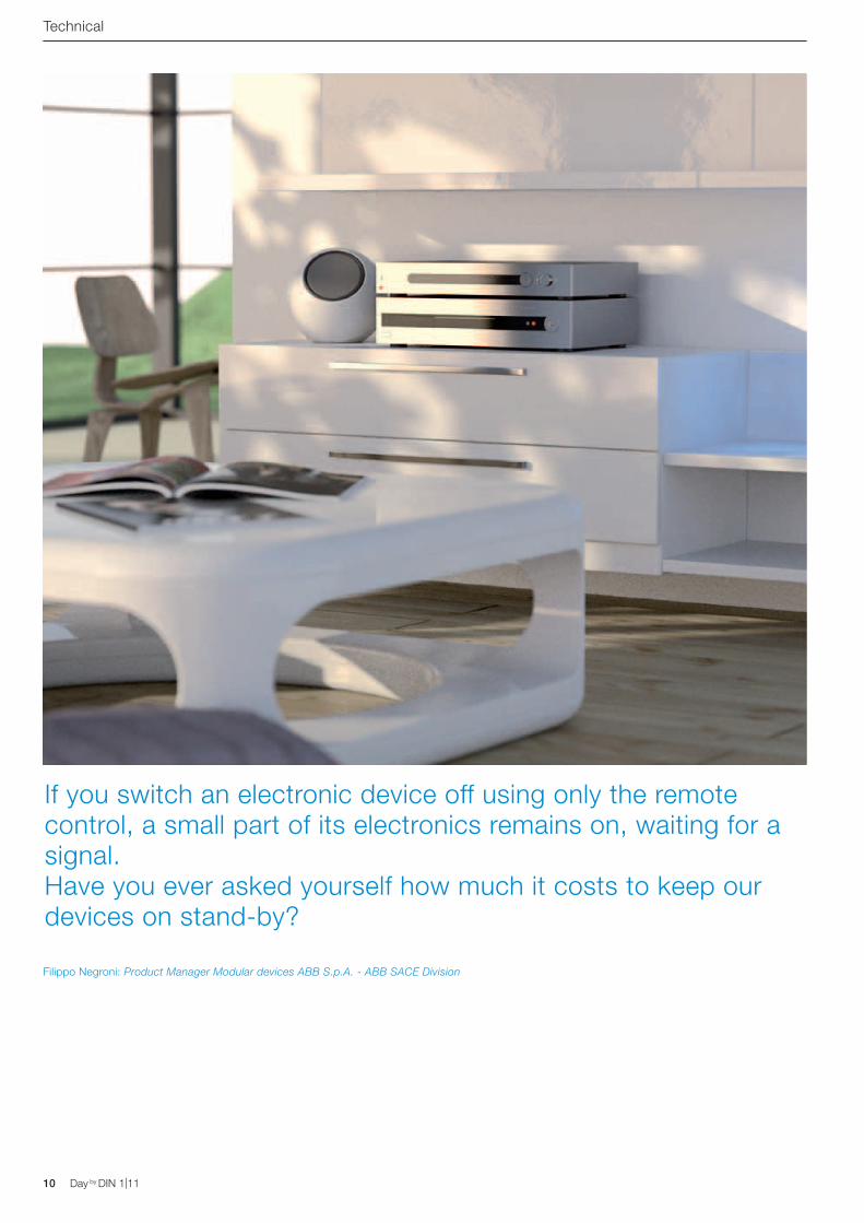
If you switch an electronic device off using only the remote control, a small part of its electronics remains on, waiting for a signal. Have you ever asked yourself how much it costs to keep our devices on stand-by?
Filippo Negroni: Product Manager Modular devices ABB S.p.A. - ABB SACE Division
Day by DIN 1|11 11Day by DIN 1|11
Technical
For several years now, electronic devices for domestic use have been designed to function in three ways: on, off and on stand-by. This third
mode allows a television or a decoder to remain off but to be switched on again with the simple touch of a remote control button. At a technical level, stand-by is an electronic circuit which remains in function waiting for a signal: it is as if the television was sleeping with one eye closed and one eye open.
How much does stand-by cost the citizen and the environment?
Household appliances use a small amount of energy even on stand-by, i.e. when they are not switched on. The red light which remains illuminated on the device is the standard indicator of this state. All devices equipped with a remote control such as televisions, DVD players, decoders and Hi Fi's have stand by mode. Other electrical appliances, even though not equipped with a remote control, sometimes do not have an off switch: video game consoles, computers, etc.; these do never sleep either. All of the devices in which a display or a red/green LED remains on can use up to 20 W or more each time they are left on stand-by.
Let's try and calculate: five devices on stand-by in a living room, most of which are
not of the latest generation, 22 hours a day, 365 days a year, with an average cost of 15 cents per kWh. In one year our restless energy consumers result in a bill of approximately 60 euro:
0.01 [kW] x 5 [devices] x 22 [hours] x 365 [days] x 0.15 [euro] = 60.2 [euro]
Quite an expense - with which we could pay for a beautiful Christmas present, half an installment on the car, a fast food dinner, three months of pay TV subscription or something else - especially if we consider the fact that we are spending all that money in order to keep the devices off!
If there are more devices or older devices the annual cost of stand by could be even higher, easily reaching € 150 per year. And we are only talking about the living room!
If we look at the environment, then the cost is even higher: many studies which have been carried out in developed countries from Italy to Australia, from Japan to the United States have documented that stand by alone accounts for approximately 10% of domestic consumption.
In the United States alone domestic devices kept on stand-by use 64 MWh, the entire production of approximately 18 medium sized electric power stations. It is a global
problem with a world wide impact which, as is often the case, can be resolved with the commitment of each one of us.
In our own little way... we too can do something
Reducing the economic and environmental effects of stand-by does not only mean decreasing the consumption of appliances, something which International Bodies and consumer electronics manufacturers are working on, but also changing the habits of the end user: to solve this problem we have come up with a solution to ensure that the system's consumer panel switches off all the appliances on stand-by. In this way, not only can the user save a fair amount of money each year, but we also protect your appliances from storms, short circuits or premature ageing.
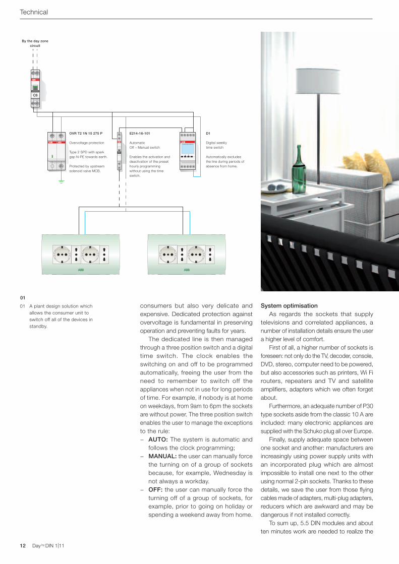
Downstream from the "day zone power" we have placed a dedicated MCB, as shown in figure 1, which exclusively powers the outlets to which all of the appliances which have a stand by function are connected. Considering the low overall use of power, a 6 A C curve device can be sufficient.
After the switch we have inserted a SPD: electronic appliances are not only energy
Dear stand-by, how much you are costing me...
C6
12 Day by DIN 1|11 Day by DIN 1|11
consumers but also very delicate and expensive. Dedicated protection against overvoltage is fundamental in preserving operation and preventing faults for years.
The dedicated line is then managed through a three position switch and a digital time switch. The clock enables the switching on and off to be programmed automatically, freeing the user from the need to remember to switch off the appliances when not in use for long periods of time. For example, if nobody is at home on weekdays, from 9am to 6pm the sockets are without power. The three position switch enables the user to manage the exceptions to the rule:
− AUTO: The system is automatic and follows the clock programming;
− MANUAL: the user can manually force the turning on of a group of sockets because, for example, Wednesday is not always a workday.
− OFF: the user can manually force the turning off of a group of sockets, for example, prior to going on holiday or spending a weekend away from home.
System optimisation As regards the sockets that supply
televisions and correlated appliances, a number of installation details ensure the user a higher level of comfort.
First of all, a higher number of sockets is foreseen: not only do the TV, decoder, console, DVD, stereo, computer need to be powered, but also accessories such as printers, Wi Fi routers, repeaters and TV and satellite amplifiers, adapters which we often forget about.
Furthermore, an adequate number of P30 type sockets aside from the classic 10 A are included: many electronic appliances are supplied with the Schuko plug all over Europe.
Finally, supply adequate space between one socket and another: manufacturers are increasingly using power supply units with an incorporated plug which are almost impossible to install one next to the other using normal 2-pin sockets. Thanks to these details, we save the user from those flying cables made of adapters, multi-plug adapters, reducers which are awkward and may be dangerous if not installed correctly.
To sum up, 5.5 DIN modules and about ten minutes work are needed to realize the
Technical
01
01 A plant design solution which allows the consumer unit to switch off all of the devices in standby.
OVR T2 1N 15 275 P Overvoltage protection Type 2 SPD with spark gap N-PE towards earth. Protected by upstream solenoid valve MCB.
By the day zone circuit
E214-16-101 Automatic Off – Manual switch Enables the activation and deactivation of the preset hourly programming without using the time switch.
D1 Digital weekly time switch Automatically excludes the line during periods of absence from home.
Day by DIN 1|11 13Day by DIN 1|11
'no stand-by' line to power the group of sockets: given the annual cost of stand-by, it is highly likely that the user makes back the investment in a very short period of time.
Technical
Filippo NegroniProduct ManagerModular DIN Rail ProductsABB S.p.A. - ABB SACE Division
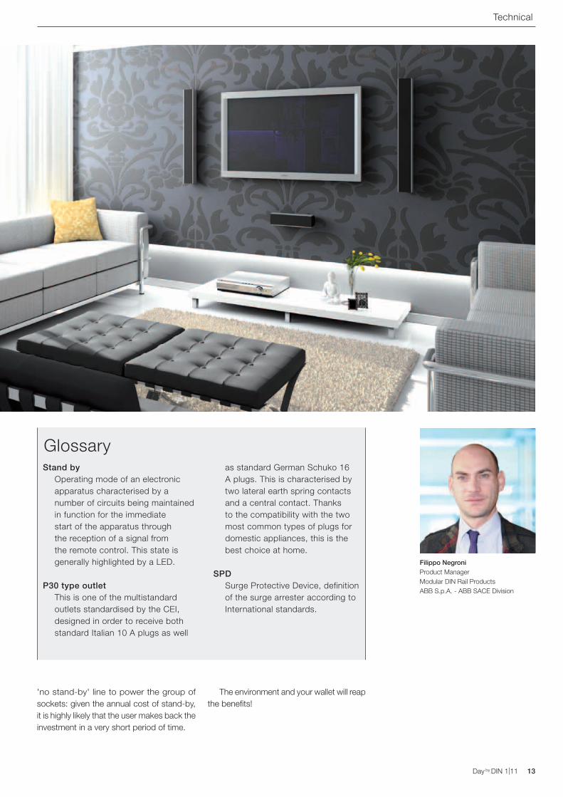
GlossaryStand by
Operating mode of an electronic apparatus characterised by a number of circuits being maintained in function for the immediate start of the apparatus through the reception of a signal from the remote control. This state is generally highlighted by a LED.
P30 type outletThis is one of the multistandard outlets standardised by the CEI, designed in order to receive both standard Italian 10 A plugs as well
as standard German Schuko 16 A plugs. This is characterised by two lateral earth spring contacts and a central contact. Thanks to the compatibility with the two most common types of plugs for domestic appliances, this is the best choice at home.
SPDSurge Protective Device, definition of the surge arrester according to International standards.
The environment and your wallet will reap the benefits!
14 Day by DIN 1|11 Day by DIN 1|11
Case History
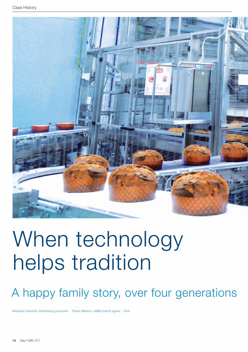
When technology helps tradition A happy family story, over four generationsMaurizio Gambini: Advertising journalist - Paolo Mellano: ABB branch agent - Turin
Day by DIN 1|11 15Day by DIN 1|11
Case History
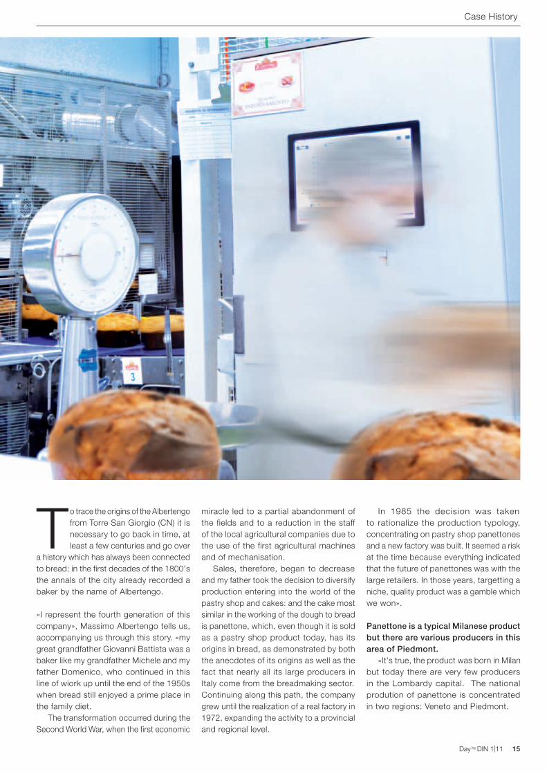
To trace the origins of the Albertengo from Torre San Giorgio (CN) it is necessary to go back in time, at least a few centuries and go over
a history which has always been connected to bread: in the first decades of the 1800's the annals of the city already recorded a baker by the name of Albertengo.
«I represent the fourth generation of this company», Massimo Albertengo tells us, accompanying us through this story. «my great grandfather Giovanni Battista was a baker like my grandfather Michele and my father Domenico, who continued in this line of wiork up until the end of the 1950s when bread still enjoyed a prime place in the family diet. The transformation occurred during the Second World War, when the first economic
miracle led to a partial abandonment of the fields and to a reduction in the staff of the local agricultural companies due to the use of the first agricultural machines and of mechanisation. Sales, therefore, began to decrease and my father took the decision to diversify production entering into the world of the pastry shop and cakes: and the cake most similar in the working of the dough to bread is panettone, which, even though it is sold as a pastry shop product today, has its origins in bread, as demonstrated by both the anecdotes of its origins as well as the fact that nearly all its large producers in Italy come from the breadmaking sector.Continuing along this path, the company grew until the realization of a real factory in 1972, expanding the activity to a provincial and regional level.
In 1985 the decision was taken to rationalize the production typology, concentrating on pastry shop panettones and a new factory was built. It seemed a risk at the time because everything indicated that the future of panettones was with the large retailers. In those years, targetting a niche, quality product was a gamble which we won».
Panettone is a typical Milanese product but there are various producers in this area of Piedmont. «It's true, the product was born in Milan but today there are very few producers in the Lombardy capital. The national prodution of panettone is concentrated in two regions: Veneto and Piedmont.
16 Day by DIN 1|11 Day by DIN 1|11
Case History
This is probably due to the fact that the production of panettone is seasonal so this was an ideal area for it, as there was already a mentality predisposed to seasonal work, given the agricultural nature of the territory».
What does a niche product have to concentrate on to overcome the competition of the large brands on the market? «It's with the growth of the large distributors, thanks to the elevated amounts, that the most famous brands develop and become big, that they necessarily have to concentrate on the policy of moderate prices. Companies that make quality the objective of their strategy are able to find space in this scenario. Ours is a product where you don't have to invent anything;
you need to follow the recipes that have been passed down by our fathers because the traditional panettone has always been high quality. So the market has become divided, just as happened in the wine sector, between even well-known companies who create products in large amounts and artisans who produce panettone of high quality in limited amounts. In conclusion, it's the quality which enables us to continue to work with success in this sector».
Operating on an international level while still remaining at an artisan level. «To us it's important to remain defined as artisans: we have 25 permanent employees and hundreds of seasonal employees and we produce between 14,000 and 16,000
01
02
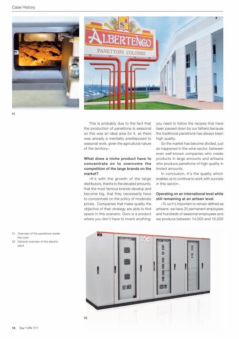
01 Overview of the panettone inside the oven
02 General overview of the electric plant
DMTME
DMTME modular multimeter are the ideal instruments to be installed in distribution panels. They directly and indirectly measure the single-phase currents and voltages, the frequency, the phase shift and the power factor of the three-phase system through current transformers.
Day by DIN 1|11 17Day by DIN 1|11
Case History
panettone a day. We work in a specialist sector and have been sending our products abroad for 15 years: our first foreign customer was Australian and they remain one of our distributors to this day. And the success is even more meaningful because in our sector you win customers mainly by 'word of mouth' which you only achieve if you work with a high level of quality. Winning over a customer is very difficult but then their loyalty is assured because the appreciation is connected to the taste of the product and other traditional factors which are hard to replace. A result which also derives from the selection of suppliers and raw materials: for example, we buy the grain directly in Australia and use it to produce the flours; we buy the oranges in Sicily which are then candied according to our indications; we carefully select the eggs and other ingredients. In doing this we have been able to create a particular feeling with customers who are looking for quality».
What are the features which set apart a high quality panettone from an industrial one? «That's a difficult question to answer. As it is generally eaten during the festivities at the end of an abundant meal, and not being a cake that particularly stresses the taste buds, when a person is able to eat a slice of panetton and feels like eating another one, that is the “litmus test” of a high-quality panettone. Even if you're full you must feel the need to eat more».
On a technological level, what are the requirements for a production plant? «This plant was realized in order to continue on the road of traditional production. In this structure we have tried to draw on all the experiences we had in the old production unit, creating technological systems equipped with sophisticated electronic controls, such as air filtration, and production systems which enable our qualitative standards to be guaranteed. Panettone is a very simple product, without any particular secrets even though it is one of the most difficult products that are cooked in an oven. It is a very demanding cake which requires specific machines which can only be used for this type of product. This is why all of the production equipment, from the oven to the room
where the dough is worked and the transfer for the traditional cooling of turned over panettones, even though they derive from systems which are also used in large scale industries, have been personalized according to our indications. One of the particularities of our apparatus is the special ovens for the production of panettone weighing from 4 to 10 kgs, something that very few are capable of producing in Italy».
What are the most critical factors in the panettone industry which can influence the quality of the product? «Definitely one of the biggest problems which we face is maintaining the temperature of the environment and the air quality to ensure the correct rising of the dough. This is why we have designed a factory in which the air is filtered throughout and the temperature is electronically controlled. The ventilation system is realized with anti-microbial channels of a level equal to that in hospitals and is controlled by ABB inverters to ensure the emission of the correct air quality. The objective was to realize a structure which was completely controllable and managed like a large technological plant: we are able to access all essential information from each PC, from the quantity of CO2 in the air to the level of water in the well, to the access control,
Panettone is a very simple product, without any particular secrets even though it is one of the most difficult products that are cooked in an oven.
18 Day by DIN 1|11
to hourly production numbers. We have a totally integrated control system which includes both the plant as well as the home automation system of the offices».
Is it important to have everything constantly under control? «The concept of control is inherent in the Albertengo company mentality», specifies Ivo Panero, of Domotica Labs, who handled the design of the domotic system. «As I have already said, the need to monitor production, the temperature of the oven and that of the refrigerators which store the raw material is fundamental for the quality of the final product. This is why, during the design phase of the new structure, it was decided, on the advice of ABB, that it would be very interesting to extend this type of philosophy to the offices and the realization of a home automation system using ABB i-bus® KNX technology proved itself to be the most natural solution. This choice, besides having remarkably simplified the system, also allowed the project to grow as we went along, adapting to the requirements that emerged from time to time, thanks to the flexibility of the system and the apparatus used for the electric distribution and domotics».
Which factors led you to select ABB products? «When Mr. Albertengo involved me in this project», explains Andrea Battisti, retail manager of the branch office Comoli Ferrari di Savigliano, «I immediately understood, that given its complexity, it was necessary to decide on a supplier in a position to offer a complete package of products in order to satisfy all the different requirements, from the consumer units, to the power switches, from command and control modular devices to the channels for cables, from the sensors to the inverter for the ventilation system. We didn't just have to consider the price. Furthermore, entrusting the project to only one supplier considerably reduced any problems. I was sure that in choosing ABB and the professionality of Paolo Mellano, of the ABB Sales Office in Turin, we would be able to succeed in satisfying the requirements of the customer, supplying all of the materials within the agreed times. And in the end it was a collaboration which satisified everybody, leading to the creation of an effective and professional system».
Case History
03
ProfessionalsRealsation of electric plantsSancassiano Elettronica Srl.Roddi, CN
Realization of Bt board cables.CTE Energy Srl.Trinità CN
Home automation system projectDomotica LabsEng. Ivo PaneroGenola, CN
Electric material distributorComoli FerrariSavigliano CN branchMr. Andrea Battisti
ABB branch Sales Manager - TurinPaolo Mellano
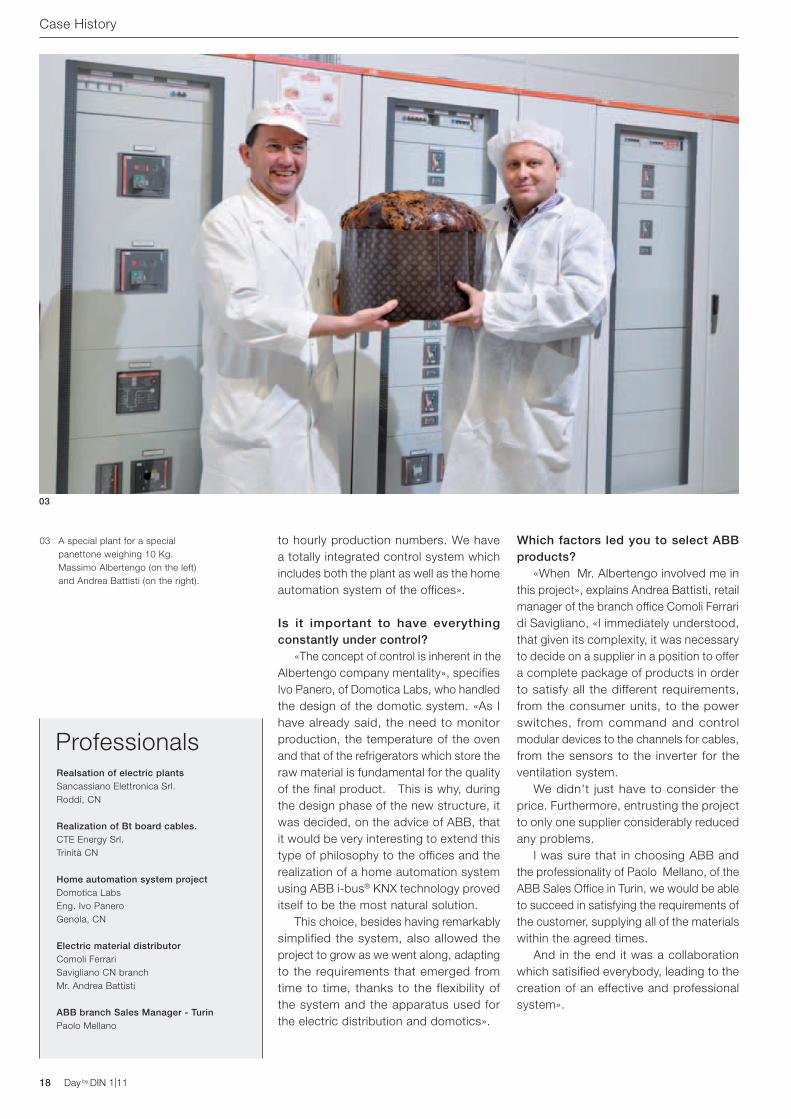
03 A special plant for a special panettone weighing 10 Kg. Massimo Albertengo (on the left) and Andrea Battisti (on the right).
Day by DIN 1|11
E 90 range. Designed by ABB for the most de-manding customers
ABB SACEA division of ABB S.p.A.Modular DevicesTel. 02 9034.1www.abb.it
Disconnecting and switching suitability, efficient dissipation of heat and certified according to several International Standards are essential requirements to satisfy the expectations of the most demanding clients. ABB has dedicated the passion, skill and creativity of its designers to the development of a new range of E 90 fuse switch disconnectors and fuse holders. The result is the first fuse switch disconnector AC-22B IMQ and UR up to 32 A and 690 V.http://www.abb.com/abblibrary/DownloadCenter/ - 2CSC444002B0902
20 Day by DIN 1|11 Day by DIN 1|11
LM
Urban legendsExploding the myths and reconsidering convictionsNowadays we use surge protective dvices every day but we still have doubts and curiosities fed by the many urban legends on the subject. Let's look at a few and try to better understand.
Emanuele Tosatti: Product Manager Modular devices ABB S.p.A. - ABB SACE Division
Day by DIN 1|11 21Day by DIN 1|11
LM
“The discharge kiloamps of a SPD must be coordinated with the short circuit current of the panel” This belief is due to a misunderstanding. The short circuit current of a panel and the discharge current of an SPD are both measured in kiloamps. However, a short circuit current normally has a sine-wave shape with a frequency of 50 Hz whilst the discharge current of a SPD has the form of a very brief impulse of just a few microseconds. Consequently, even the energy content (I2t) of a short circuit and of a discharge are very different. Once the misunderstanding has been cleared up it is evident that there is no relationship between the Isc of a switchboard and the discharge current of a SPD.
So, how do you choose the discharge current or impulse of a SPD? It is easier than it seems:
− for Type 1 there is nothing to choose, the value is set by Standard CEI 81-10: nearly all SPDs have a value of 25kA per pole and are equipped, therefore, for the worst case foreseen by the Standards in force;
− for Type 2, the maximum discharge current value foreseen by the standard CEI 81-10 is 5 kA;, therefore, a Type 2 SPD must have at least 5 kA of In.
For practical reasons it is nearly always advisable to choose an SPD with at least 20 kA of In to guarantee an adequate length of working life.
22 Day by DIN 1|11 Day by DIN 1|11
“In a triphase system with 400 Va.c. voltage a SPD with a rated voltage of 400 Va.c. must be installed” Other misunderstandings. Type 1 and Type 2 surge protective devices are designed to be installed between network and ground, not in series. The “rated voltage” of a SPD is, therefore, that measured between the active conductors (phase and neutral) and the earth conductor. In a 400 V three-phase network, with or without neutral, this voltage will always be equal to 230 V! The only rare case in which it is necessary to use SPDs with UN
400 V on a 400 V three-phase network is in IT systems: in these, in the case of a first ground fault, an automatic interruption of the power supply is not foreseen. A SPD with 230 V voltage would be subjected to a phase/earth voltage much higher than the nominal voltage and consequently there would be the risk of a failure or fire.
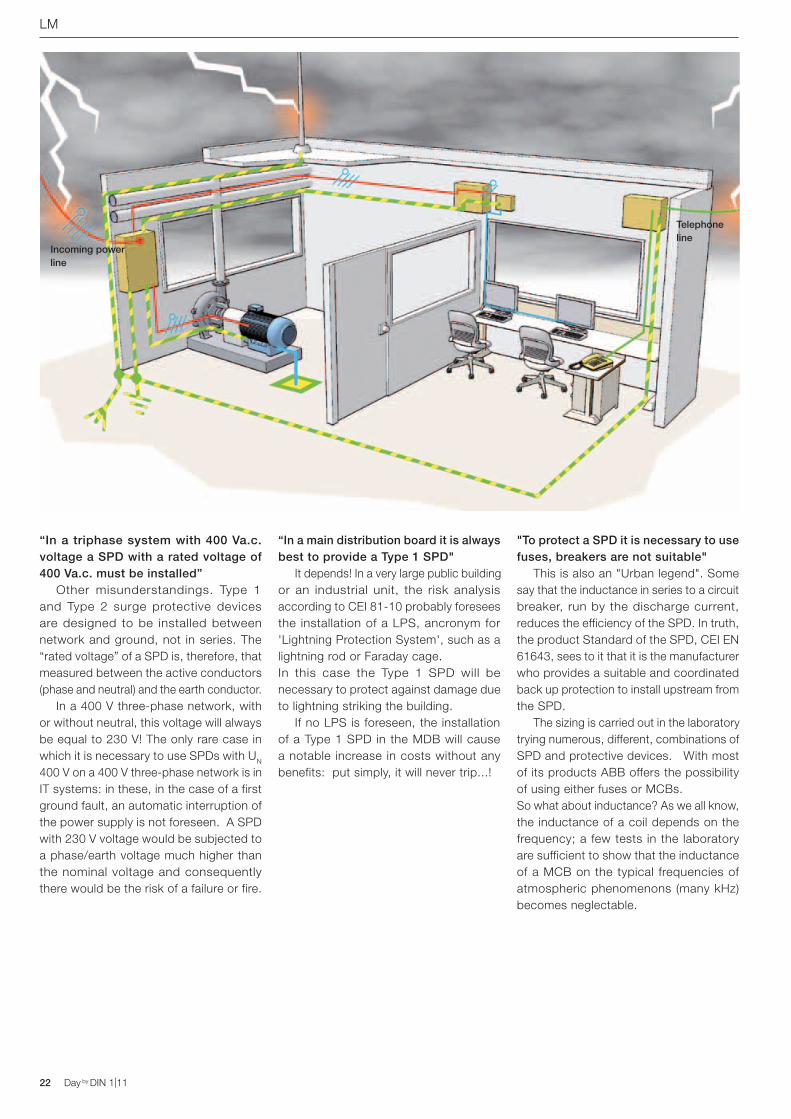
“In a main distribution board it is always best to provide a Type 1 SPD" It depends! In a very large public building or an industrial unit, the risk analysis according to CEI 81-10 probably foresees the installation of a LPS, ancronym for 'Lightning Protection System', such as a lightning rod or Faraday cage.In this case the Type 1 SPD will be necessary to protect against damage due to lightning striking the building. If no LPS is foreseen, the installation of a Type 1 SPD in the MDB will cause a notable increase in costs without any benefits: put simply, it will never trip...!
"To protect a SPD it is necessary to use fuses, breakers are not suitable" This is also an "Urban legend". Some say that the inductance in series to a circuit breaker, run by the discharge current, reduces the efficiency of the SPD. In truth, the product Standard of the SPD, CEI EN 61643, sees to it that it is the manufacturer who provides a suitable and coordinated back up protection to install upstream from the SPD. The sizing is carried out in the laboratory trying numerous, different, combinations of SPD and protective devices. With most of its products ABB offers the possibility of using either fuses or MCBs.So what about inductance? As we all know, the inductance of a coil depends on the frequency; a few tests in the laboratory are sufficient to show that the inductance of a MCB on the typical frequencies of atmospheric phenomenons (many kHz) becomes neglectable.
LM
Incoming power line
Telephone line
Day by DIN 1|11 23Day by DIN 1|11
“When lightning strikes and the SPD trips, the SPD must always be replaced” No, the SPDs are not "disposable"! Also because, if this were so, since there can be numerous atmospheric discharges during a thunderstorm, the SPD would be totally ineffective. In reality, SPDs are designed and tested in order to trip and to return as good as new at least 20 times, if subjected to their rated discharge current. Given that statistically speaking the discharge current induced by the atmospheric phenomenon is inferior to the rated current, the SPD can trip even hundreds of times before reaching the so-called “end of life”. This is the reason why SPDs are installed every day, but changing a cartridge at the end of its life is a rare occurence.
“A Type 2 SPD is nothing more than a varistor…” The varistor is a fundamental component of all Type 2 SPDs, but we must not forget that varistors have two characteristics which a SPD must remedy: they end their operative life in short circuit and they conduct a small permanent current. In order to prevent the short circuit effects on the life of the varistor, a small, essential element is provided inside a SPD: a thermal disconnector which isolates the varistor from the network in case of overheating, ensuring a safe end of life for the SPD. Instead, in order to prevent the permanent earth current, which could involve the risk of indirect contacts, in some Type 2 SPDs the N-PE module, which is designed to lead the discharge current towards the earth conductor, is not realized with a varistor, but with a voltage switching type element (for example, a spark gap), able to permanently prevent the current flow towards the PE. All ABB OVR T2 1N and 3N SPDs are realized with this technology.
“The remote signalling contact tells me the SPD has intervened” No, the signalling contact switches only when the SPD has reached the end of its operative life. Very useful in the event of unprotected distribution boards, the information can be used, for example, in order to suddenly replace the cartridge in end of life and to restore the protection from the overvoltages.
“A SPD for alternating current can also be used in direct current; it is just a matter of multiplying its rated voltage by the root of two” This is the principle for which many SPD for alternating current at 400 V have without warning become SPDs for photovoltaic at 600 V DC. The ABB position has always been very clear on this point: the varistors sooner or later go into short circuit and interrupting a short circuit in direct current is much most difficult than in alternating current. It cannot, therefore, be absolutely guaranteed that the thermal disconnector integrated in a SPD designed for alternating current is able to guarantee the disconnection when the same SPD is installed in a photovoltaic system: the manufacturer must test it in a laboratory and, in general, must declare new back up protections, sized to continuous application.
LM
Events
Safety fairThe participation of ABB in a Safety Fair has provoked a great deal of interest, with the presentation of new ABB i-bus® KNX products dedicated to Home& Building Automation for residential and hotel applications and the presentation of the ABB-SAET solution “Building integration technologies” for the integrated management of all the technological systems of a building A complete range of solutions for security, comfort and energy saving.
ABB Energy Efficiency Award 2010Energy efficiency awarded. The four important companies active in various industrial and tertiary sectors are Accenture, Fiera Milano, RFT of the SKF group and Unicalce which were awarded the ABB Energy Efficiency Award 2010 for having realized energy efficiency improvement interventions in their own buildings, choosing ABB as their technical partner for the designing of the interventions and for the supply and installation of the equipment necessary in order to realize them.Energy efficiency is one of the pillars of the global strategies of ABB and this initiative aims to both spread a greater knowledge on the topic, and demonstrate that even simple and rapid interventions can help to achieve consistent savings with extremely short pay back times.
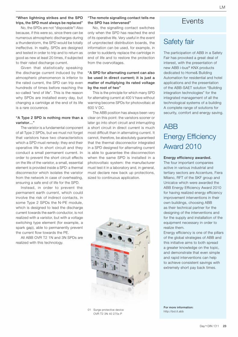
For more information:http://bol.it.abb01 Surge protective device
OVR T2 3N 40 275s P
24 Day by DIN 1|11 Day by DIN 1|11
Technical
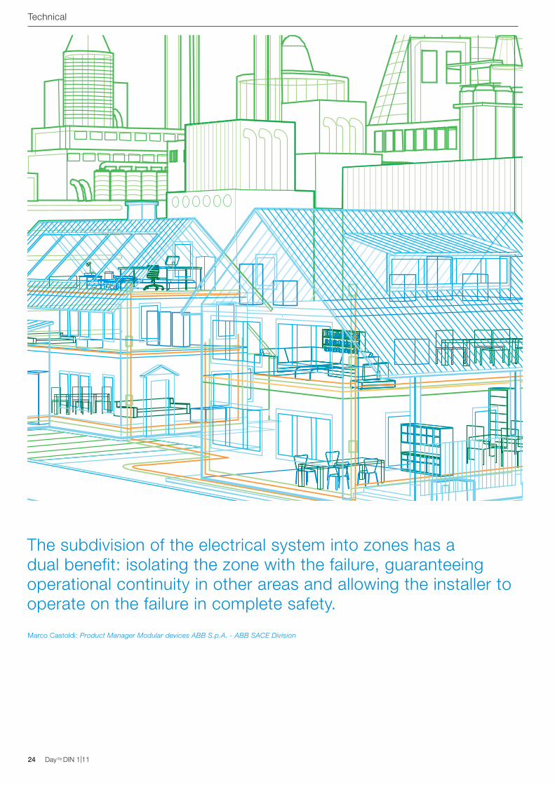
The subdivision of the electrical system into zones has a dual benefit: isolating the zone with the failure, guaranteeing operational continuity in other areas and allowing the installer to operate on the failure in complete safety.
Marco Castoldi: Product Manager Modular devices ABB S.p.A. - ABB SACE Division
Day by DIN 1|11 25Day by DIN 1|11
Technical
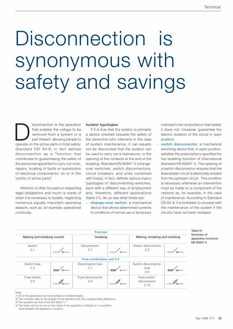
Table 01Summary of apparatus functions EN 60947-3
Disconnection is the operation that enables the voltage to be removed from a system or a part thereof, allowing people to
operate on the active parts in total safety. Standard CEI 64-8, in fact defines disconnection as a “function that contributes to guaranteeing the safety of the personnel appointed to carry out work, repairs, locating of faults or substitution of electrical components, on or in the vicinity of active parts"
Attention is often focused on respecting legal obligations and much is made of when it is necessary to isolate, neglecting numerous equally important operating aspects, such as, for example, operational continuity.
Isolator typologies If it is true that the isolator is primarily a device oriented towards the safety of the personnel who intervene in the case of system maintenance, it can equally not be discounted that the isolator can be used to carry out a manoeuvre, or the opening of the contacts at the end of the isolating. Standard EN 60947-3 (change-over switches, switch disconnectors, circuit breakers, and units combined with fuses), in fact, defines various macro typologies of disconnecting switches, each with a different way of employment and, therefore, different applications (table 01); let us see what these are:
− change-over switch: a mechanical device that allows determined currents in conditions of normal use or temporary
overload to be conducted or interrupted; it does not, however, guarantee the electric isolation of the circuit in open position;
− switch disconnector: a mechanical switching device that, in open position, satisfies the prescriptions specified for the isolating function of international Standard EN 60947-3. The opening of a switch disconnector ensures that the downstream circuit is electrically isolated from the upstream circuit. This condition is necessary whenever an intervention must be made on a component of the network as, for example, in the case of maintenance. According to Standard CEI 64-8, it is forbidden to proceed with the maintenance of the system if the circuits have not been isolated;
Disconnection issynonymous with safety and savings
Function
Making and breaking current Isolating Making, breaking and isolating
Switch 2.1
Disconnector 2.2
Switch-disconnector 2.3
Fuse combination unit 2.4
Switch-fuse 2.5
Disconnector-fuse2.7
Switch-disconnector-fuse2.9
Fuse-switch2.6
Fuse-disconnector2.8
Fuse-switch-disconnector
2.10
Note:1) All of the apparatus may have simple or multiple breaks.2) The numbers refer to the articles of the standard with the corresponding definitions.3) The symbols are that of the IEC 60617-74) The fuses can be on one or two sides of the apparatus contacts or in a position
fixed between the apparatus contacts.
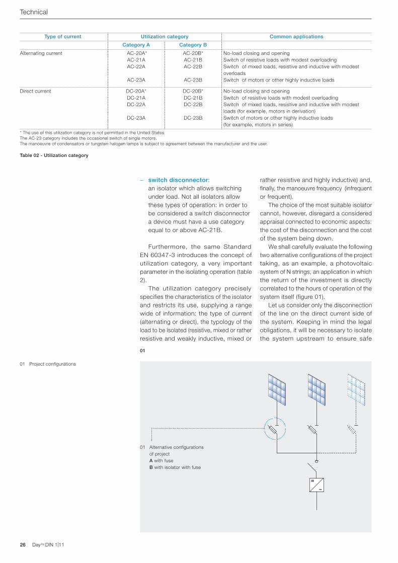
01 Project configurations
26 Day by DIN 1|11 Day by DIN 1|11
Type of current Utilization category Common applications
Category A Category B
Alternating current AC-20A*AC-21AAC-22A
AC-23A
AC-20B*AC-21BAC-22B
AC-23B
No-load closing and opening Switch of resistive loads with modest overloadingSwitch of mixed loads, resistive and inductive with modest overloadsSwitch of motors or other highly inductive loads
Direct current DC-20A*DC-21ADC-22A
DC-23A
DC-20B*DC-21BDC-22B
DC-23B
No-load closing and opening Switch of resistive loads with modest overloadingSwitch of mixed loads, resistive and inductive with modest loads (for example, motors in derivation)Switch of motors or other highly inductive loads (for example, motors in series)
* The use of this utilization category is not permitted in the United States The AC-23 category includes the occasional switch of single motors. The manoeuvre of condensators or tungsten halogen lamps is subject to agreement between the manufacturer and the user.
− switch disconnector: an isolator which allows switching under load. Not all isolators allow these types of operation: in order to be considered a switch disconnector a device must have a use category equal to or above AC-21B.
Furthermore, the same Standard EN 60347-3 introduces the concept of utilization category, a very important parameter in the isolating operation (table 2). The utilization category precisely specifies the characteristics of the isolator and restricts its use, supplying a range wide of information: the type of current (alternating or direct), the typology of the load to be isolated (resistive, mixed or rather resistive and weakly inductive, mixed or
rather resistive and highly inductive) and, finally, the manoeuvre frequency (infrequent or frequent). The choice of the most suitable isolator cannot, however, disregard a considered appraisal connected to economic aspects: the cost of the disconnection and the cost of the system being down. We shall carefully evaluate the following two alternative configurations of the project taking, as an example, a photovoltaic system of N strings, an application in which the return of the investment is directly correlated to the hours of operation of the system itself (figure 01). Let us consider only the disconnection of the line on the direct current side of the system. Keeping in mind the legal obligations, it will be necessary to isolate the system upstream to ensure safe
Table 02 - Utilization category
01
01 Alternative configurations of project A with fuseB with isolator with fuse
Technical
GlossaryDisconnection
Operation that allows voltage to be removed from a system or one of its part, allowing people to operate on the active parts in total safety.
SwitchMechanical device that allows determined currents in conditions of normal use or temporary overload to be conducted or interrupted; it does not guarantee the electric disconnection of the circuit in open position.
IsolatorMechanical switching device which, in open position, satisfies the prescriptions specified for the disconnecting function by International Standard EN 60947-3.
Switch disconnector Isolator which allows switching under load.
Utilization categoryPrecisely defines the characteristics of the isolator and restricts its use.
Day by DIN 1|11 27Day by DIN 1|11
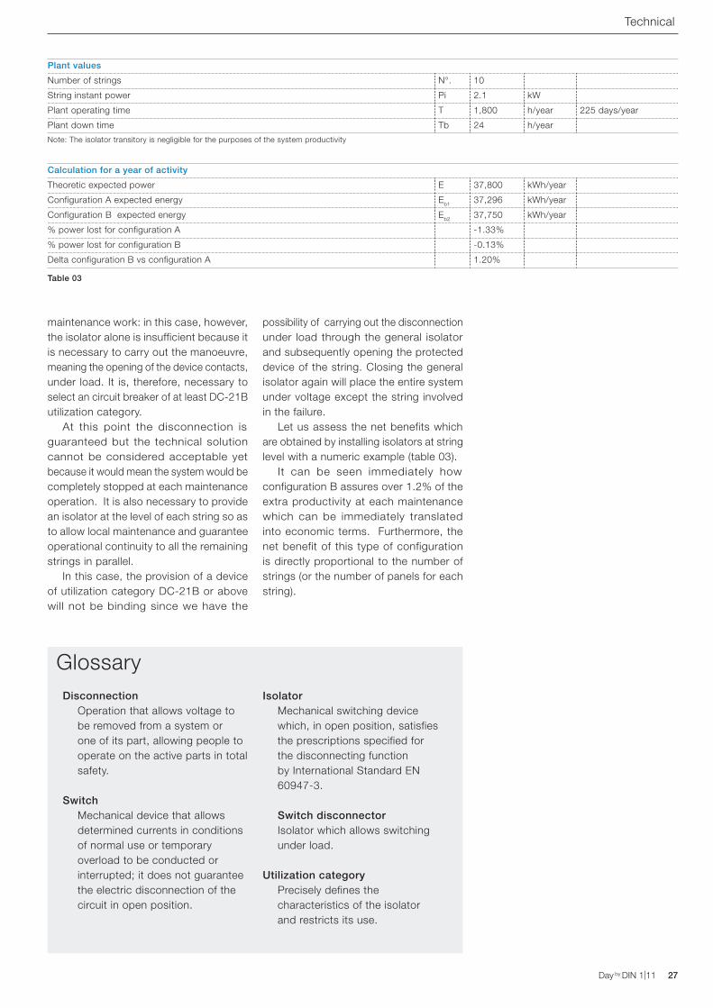
maintenance work: in this case, however, the isolator alone is insufficient because it is necessary to carry out the manoeuvre, meaning the opening of the device contacts, under load. It is, therefore, necessary to select an circuit breaker of at least DC-21B utilization category. At this point the disconnection is guaranteed but the technical solution cannot be considered acceptable yet because it would mean the system would be completely stopped at each maintenance operation. It is also necessary to provide an isolator at the level of each string so as to allow local maintenance and guarantee operational continuity to all the remaining strings in parallel. In this case, the provision of a device of utilization category DC-21B or above will not be binding since we have the
Plant values
Number of strings N°. 10
String instant power Pi 2.1 kW
Plant operating time T 1,800 h/year 225 days/year
Plant down time Tb 24 h/year
Note: The isolator transitory is negligible for the purposes of the system productivity
Calculation for a year of activity
Theoretic expected power E 37,800 kWh/year
Configuration A expected energy Eb1 37,296 kWh/year
Configuration B expected energy Eb2 37,750 kWh/year
% power lost for configuration A -1.33%
% power lost for configuration B -0.13%
Delta configuration B vs configuration A 1.20%
possibility of carrying out the disconnection under load through the general isolator and subsequently opening the protected device of the string. Closing the general isolator again will place the entire system under voltage except the string involved in the failure. Let us assess the net benefits which are obtained by installing isolators at string level with a numeric example (table 03). It can be seen immediately how configuration B assures over 1.2% of the extra productivity at each maintenance which can be immediately translated into economic terms. Furthermore, the net benefit of this type of configuration is directly proportional to the number of strings (or the number of panels for each string).
Table 03
Technical
28 Day by DIN 1|11 Day by DIN 1|11
Technical
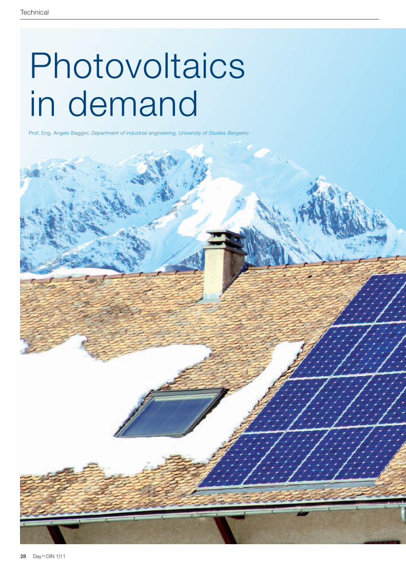
Photovoltaicsin demandProf. Eng. Angelo Baggini: Department of industrial engineering, University of Studies Bergamo
Day by DIN 1|11 29Day by DIN 1|11
Technical
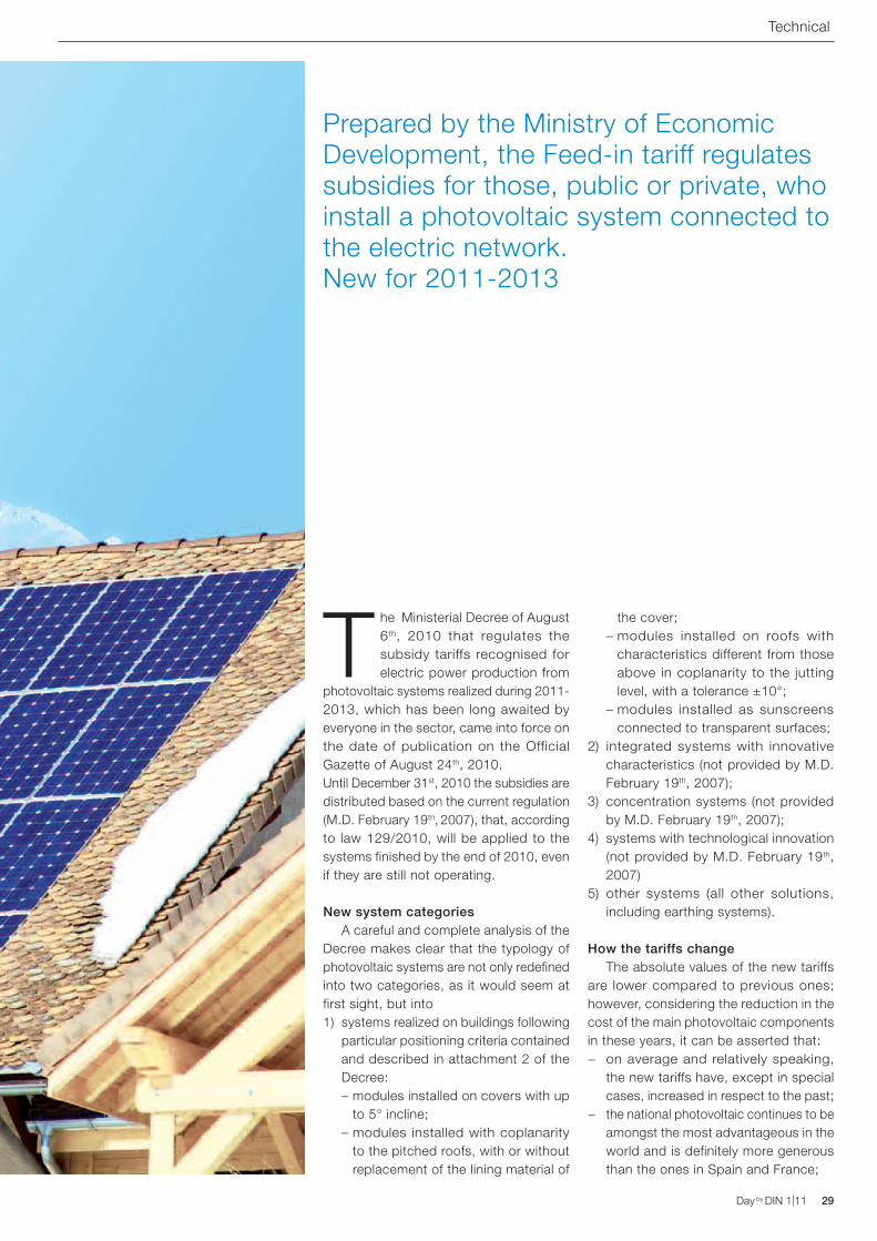
The Ministerial Decree of August 6th, 2010 that regulates the subsidy tariffs recognised for electric power production from
photovoltaic systems realized during 2011-2013, which has been long awaited by everyone in the sector, came into force on the date of publication on the Official Gazette of August 24th, 2010.Until December 31st, 2010 the subsidies are distributed based on the current regulation (M.D. February 19th, 2007), that, according to law 129/2010, will be applied to the systems finished by the end of 2010, even if they are still not operating.
New system categoriesA careful and complete analysis of the
Decree makes clear that the typology of photovoltaic systems are not only redefined into two categories, as it would seem at first sight, but into1) systems realized on buildings following
particular positioning criteria contained and described in attachment 2 of the Decree:
– modules installed on covers with up to 5° incline;
– modules installed with coplanarity to the pitched roofs, with or without replacement of the lining material of
the cover; – modules installed on roofs with
characteristics different from those above in coplanarity to the jutting level, with a tolerance ±10°;
– modules installed as sunscreens connected to transparent surfaces;
2) integrated systems with innovative characteristics (not provided by M.D. February 19th, 2007);
3) concentration systems (not provided by M.D. February 19th, 2007);
4) systems with technological innovation (not provided by M.D. February 19th, 2007)
5) other systems (all other solutions, including earthing systems).
How the tariffs change The absolute values of the new tariffs
are lower compared to previous ones; however, considering the reduction in the cost of the main photovoltaic components in these years, it can be asserted that:
− on average and relatively speaking, the new tariffs have, except in special cases, increased in respect to the past;
− the national photovoltaic continues to be amongst the most advantageous in the world and is definitely more generous than the ones in Spain and France;
Prepared by the Ministry of Economic Development, the Feed-in tariff regulates subsidies for those, public or private, who install a photovoltaic system connected to the electric network. New for 2011-2013
30 Day by DIN 1|11 Day by DIN 1|11
− One thing that is certain is that the cost of electrical energy in Italy is amongst the highest in the European Union and that the subsidies are not a weight on the accounts examined by the State, but on the A3 tariff component of the bill;
− the outline of the subsequent reductions to compensate for the falling costs of the main components of the system coming from the semiconductor industry was in the plans and is ticking along nicely, in the opinion of the author.
For systems with power lower than 200 kW, the average percentage reduction of the rates of the third quarter of 2011 falls between 10% and 17% compared to the rates of 2010. For systems with power exceeding 200 kW it falls between 20% and 27%.
Summarizing the value of the energy to the subsidy, for which decreases are not foreseen, the total reduction will fall between 8% and 10%, for the small systems, and between 14% and 20%, for larger systems.
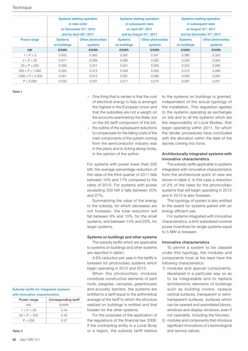
Systems on buildings and other systemsThe subsidy tariffs which are applicable
to systems on buildings and other systems are reported in table1.
A 6% reduction per year in the tariffs is foreseen for photovoltaic systems which begin operating in 2012 and 2013.
When the photovoltaic modules constitute constructive elements of pent roofs, pergolas, canopies, greenhouses and acoustic barriers, the systems are entitled to a tariff equal to the arithmetical average of the tariff to which the structure realized on buildings is entitled and that forseen for the other systems.
For the purposes of the application of the regulations of the financial law 2008, if the contracting entity is a Local Body or a region, the subsidy tariff relative
to the systems on buildings is granted, independent of the actual typology of the installation. This regulation applies to the systems operating as exchanges on site and to all the systems which are the responsibility of Local Bodies, that begin operating within 2011, for which the tender procedures have concluded with the allocation within the date of the decree coming into force.
Architecturally integrated systems with innovative characteristics
The subsidy tariffs applicable to systems integrated with innovative characteristics from the architectural point of view are shown in table 2: in this case a reduction of 2% of the rates for the photovoltaic systems that will begin operating in 2012 and in 2013 is also foreseen.
This typology of system is also entitled to the award for systems paired with an energy efficient use.
For systems integrated with innovative characteristics, a limit subsidized nominal power incentives for single systems equal to 5 MW is foreseen.
Innovative characteristicsTo permit a system to be classed
under this typology, the modules and components must at the least have the following characteristics:1) modules and special components,
developed in a particular way so as to be integratable and to replace architectonic elements of buildings such as building covers, opaque vertical surfaces, transparent or semi-transparent surfaces, surfaces which can be opened and assimilated (doors, windows and display windows, even if not openable, including the fixtures);
2) modules and components that introduce significant innovations of a technological and service nature;
Table 1
Table 2
Systems starting operation
in date order
on December 31st, 2010
and by April 20th, 2011
Systems starting operation
in subsequent date
on April 30th, 2011
and by August 31st, 2011
Systems starting operation
in subsequent date
on August 31st, 2011
and by December 31st, 2011
Power range Systems
on buildings
Other photovoltaic
systems
Systems
on buildings
Other photovoltaic
systems
Systems
on buildings
Other photovoltaic
systems
kW €/kWh €/kWh €/kWh €/kWh €/kWh €/kWh
1 ≤ P ≤ 3 0.402 0.362 0.391 0.347 0.380 0.333
3 < P ≤ 20 0.377 0.339 0.360 0.322 0.342 0.304
20 ≤ P ≤ 200 0.358 0.321 0.341 0.309 0.323 0.285
200 < P ≤ 1.000 0.355 0.314 0.335 0.303 0.314 0.266
1.000 < P ≤ 5.000 0.351 0.313 0.327 0.289 0.302 0.264
P > 5.000 0.333 0.297 0.311 0.275 0.287 0.251
Subsidy tariffs for integrated systems
with innovative characteristics
Power range Corresponding tariff
kW €/kWh
1 ≤ P ≤ 20 0.44
20 < P ≤ 200 0.40
P > 200 0.37
Technique
Day by DIN 1|11 31Day by DIN 1|11
3) modules designed and realized industrially to carry out, asides from the production of electric energy, fundamental architectonic functions such as:
− protection or thermal regulation of the building. The component must guarantee the maintenance of energy requirement levels of the building and be characterized by thermal transmittance comparable with that of the architectonic components replaced;
− modules designed to guarantee water tightness and the consequent impermeability of the building structure;
− modules designed to guarantee a mechanical seal comparable to the building element replaced. To access all subsidy tariffs the components must be installed according to the following modality:
− must rep lace arch i tecton ic components of the buildings;
− must still, however, play a role in lining of the building parts, otherwise played by building components which are not for the production of electric energy;
Table 3
Subsidy tariffs for concentration
plants
Power range Corresponding tariff
kW €/kWh
1 ≤ P ≤ 200 0.37
200 < P ≤ 1.000 0.32
P > 1.000 0.28
− from an aesthetic point of view, the photovoltaic system must, however, be harmoniously inserted into the architectonic design of the building.
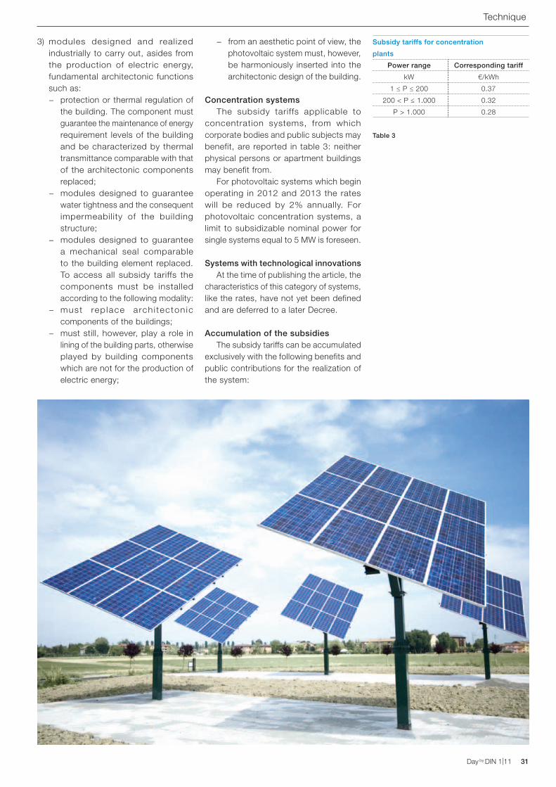
Concentration systems The subsidy tariffs applicable to
concentration systems, from which corporate bodies and public subjects may benefit, are reported in table 3: neither physical persons or apartment buildings may benefit from.
For photovoltaic systems which begin operating in 2012 and 2013 the rates will be reduced by 2% annually. For photovoltaic concentration systems, a limit to subsidizable nominal power for single systems equal to 5 MW is foreseen.
Systems with technological innovationsAt the time of publishing the article, the
characteristics of this category of systems, like the rates, have not yet been defined and are deferred to a later Decree.
Accumulation of the subsidiesThe subsidy tariffs can be accumulated
exclusively with the following benefits and public contributions for the realization of the system:
Technique
32 Day by DIN 1|11
1) contributions in capital account of an amount which does not exceed 30% of the investment for systems realized on buildings up to 3 kW;
2) contributions in capital account of an amount which does not exceed 60% of the investment:
− for systems realized on public schools or suchlike in which the contracting entity is the school or the owner of the building;
− for systems realized on public health structures;
− for systems realized on administrative headquarters which are the property of Local Bodies or Regions or Autonomous provinces;
3) contributions in capital account of an amount which does not exceed 30% of the investment in the case of systems on buildings which are different from those indicated in point 2), or on buildings which are the property of non-profit organisations of public benefit that supply social services provided for by Local Bodies and the contracting entity
of which is a Public Body or a non-profit organization of public benefit.The subsidies are not applicable if, in relation to the photovoltaic system, tax deductions have been recognized or granted.
The accumulated condit ions foreseen by the Ministerial Decree of 19th February 2007 are applied to photovoltaic systems realized with the granting of public subsidies of a national, local, regional or communitarian nature in capital account or low interest loans, provided that the bans have been published prior to the coming into force of the Decree and the systems start operating by December 31st, 2011:
− up to 20% of the subsidies in capital account or in low interest loans of a local, regional, national and communitarian nature;
− of any Body, provided it is not of a national nature, if the contracting entity of the system is a public school or such like or a public health structure.
Amendments to law March 22nd, 2010, so-called "Salva Alcoa" The tariffs foreseen for the year 2010 by the M.D. February 19th, 2007 are recognized for all entities that have concluded, by December 31st, 2010, the installation of the photovoltaic system, have communicated the completion of work to the suitable administration for the issuing of the authorisation, the manager of the network and the GSE within the same date and start operating by June 30th, 2011.
The operating procedure containing the modalities required for the presentation of the documentation of end of work has been published by the GSE with a slight delay, but is now available. To access the procedure the following conditions have to be respected:1) besides the work that determines the
electric functionality, it is necessary that the building and architectonic works connected to the integration between the system and the building in which it is inserted are completed;
2) for a photovoltaic system in particular the following components must be installed and electrically connected:
− photovoltaic modules; − sustaining structure;
− inverter; − connection cables between the
system components; − protection devices; − all of the electric panels (all of them!);
3) for the systems which can be connected to low voltage networks the entity responsible shall prepare the outlets for the adaption/insulating converter/s or transformer/s for connection to the network.
4) for larger systems connected to medium or high voltage it is necessary to include the transformation cabin/s as part of the work completion.
5) all local measures, the local inverter and all of the building works correlated to the transformation cabin must also be completed.
6) finally, the util ity system for the connection which is the responsibility of the applicant must have been realized.
The necessary documentation is composed of:
− photographs of the system (the photos of the completed system must provide a complete view of the system and its main components, modules, inverters and transformers);
− technical data of the system; − the application for access to benefits
provided by law no. 129 of August 13th, 2010 (module available on the GSE site);
− the techical card of the system printed by the portal and signed by an appointed technician;
− a copy of the application for electric connections to the suitable manager of the territorial network;
− the definitive plan of the system (including planimetry, elaborated graphics and electric layout);
− the asseveration, written and signed in the original by an appointed technician, of the total conclusion of the work;
− a copy of the authorized documentation requested and obtained for the construction of the system;
− the declaration of ownership of the system or authorization of the owner for the realization of the system;
− a copy of a valid identification documention of the contracting entity.
The manager of the network, GSE and the Administrative Bodies able to issue the authorization, each within their own field of competency, will obviously be able to implement sample controls for the verification and evidence of what has been declared.
Law August 13th, 2010, no. 129
Technical
Day by DIN 1|11
Heat up a holiday house by SMS?
Certainly.
ABB SACEA division of ABB S.p.A.Modular DevicesTel. 02 9034.1www.abb.it
The management of the holiday house is even more simple and functional! With a free ring or an SMS from a phone to the ATT modules, GSM telephone actuators make it possible to activate the boiler before arriving home or to carry out attempts to rearm household appliances in case of a blackout. ATT modules are GSM telephone actuators that answer the installation necessities in all the applicative areas ensuring the remote supervision of electrical appliances through a mobile phone. These are compatible with the SIM GSM of all mobile phone operators. These send information regarding the electric appliances monitored in real time, are simple and intuitive in only 4 DIN modules. http://www.abb.com/abblibrary/DownloadCenter/ - 2CSC441001B0902
34 Day by DIN 1|11 Day by DIN 1|11
The incandescent lamp is phased out
A little bit of history and some interesting facts
Eng. Franco Bua: ECD, Engineering Consulting and Design - Milano - Pavia
The discovery of the phenomenon of the light emission from an electric discharge, at the base of discharge lamps, dates back
to the second half of the XIX century from the work of scientists such as Charles Wheatstone and Jean Foucault. The discharge was obtained by placing two metallic elements or bars of grafite side by side in atmospheric air.
This type of lamp was used for a period of time before the invention of the incandescent light bulb and also, subsequently, where high luminous flows were required. The main disadvantages of this technique were initially the rapid consumption of the electrodes, the need to continuously regulate their distance (both for priming as well as for wear), the instability of the light produced and the excessive intensity of this for common uses. The first problems were partially resolved with the use of watch making mechanisms, that progressively drew the electrodes nearer together. The incandescent light bulb, commonly
attributed to Edison, was actually invented in 1854 by Heinrich Goebel, a German watchmaker who emigrated to America, who was not, however, in a position to industrialize and commercialize his own idea because of the limited duration of his products. During this period many inventors were working on the idea, but the problem of the first models was the rapid destruction of the filament. A problem which Thomas Alva Edison solved in 1878. Shortly before his death, Heinrich Goebel succeeded in claiming his own rights as inventor, which were then yielded to Edison by Goebel's widow after the death of the husband. The first light bulbs were composed of a glass bulb in which a vacuum had been created which contained a thread of carbonated cotton through which current travelled, until in 1903, the American William David Coolidge introduced the tungsten filament, still currently in use. Tungsten is particularly suitable for this application as it is a pure metal with the highest melting point (3422 °C), combined with the lowest vapour pressure (besides
History and surroundings
Day by DIN 1|11 35Day by DIN 1|11
the highest resistance to traction at temperatures above 1650°C amongst metals). The light is produced from the heating by Joule effect up to approximately 2700 K of the tungsten filament through which the electric current flows. Whilst operating, the sublimate tungsten and the filament become increasingly thinner until they break after approximately 1.000 hours of ignition. Besides heat, the energy is converted into light, in an amount that falls between 5 and 10%, therefore with a very low energetic efficiency. In modern light bulbs the glass bulb is
not vacuum packed but rather contains an inert gas at low pressure, usually Argon, more rarely Kripton, which allows a capacity of more than 10% approximately equal to power. These gases limit the risks of implosion and extend the life of the filament, at the same time reducing the blackening of the bulb due to the deposit of the sublimate tungsten. At the moment at which the lamp is switched on, since the filament is cold and the resistance is minor, an overcurrent of a duration of tenths of a second and equal to 10÷12 times the nominal current occurs.
History and surroundings
36 Day by DIN 1|11 Day by DIN 1|11
The end of a glorious history For reasons of energy efficiency recovery, after nearly a century and a half of history, the European Commission (Regulation EC 244/2009 in actuation of the framework directive 2005/32/EC on the ecocompatible designing of devices that consume energy) decreed the gradual ban of incandescent light bulbs.
A modernization of some details of the electric practice system is, therefore, obligatory, though already started in light of the facts.Luminous discharge sources, which will continue to increasingly occupy the spaces left free by the old incandescence lightbulb waiting for the transformation connected to LED technologies, present, besides far superior lighting efficiency, an important detail that requires a little attention system-wise: the elevated insertion current.Especially in larger systems of the tertiary sector or in the presence of emergency power supply sources, the insertion current can assume important values that must be managed with adequate devices. The main manufacturers of devices for the control of lighting supply tables with the number of controllable lamps based on its type and its power.
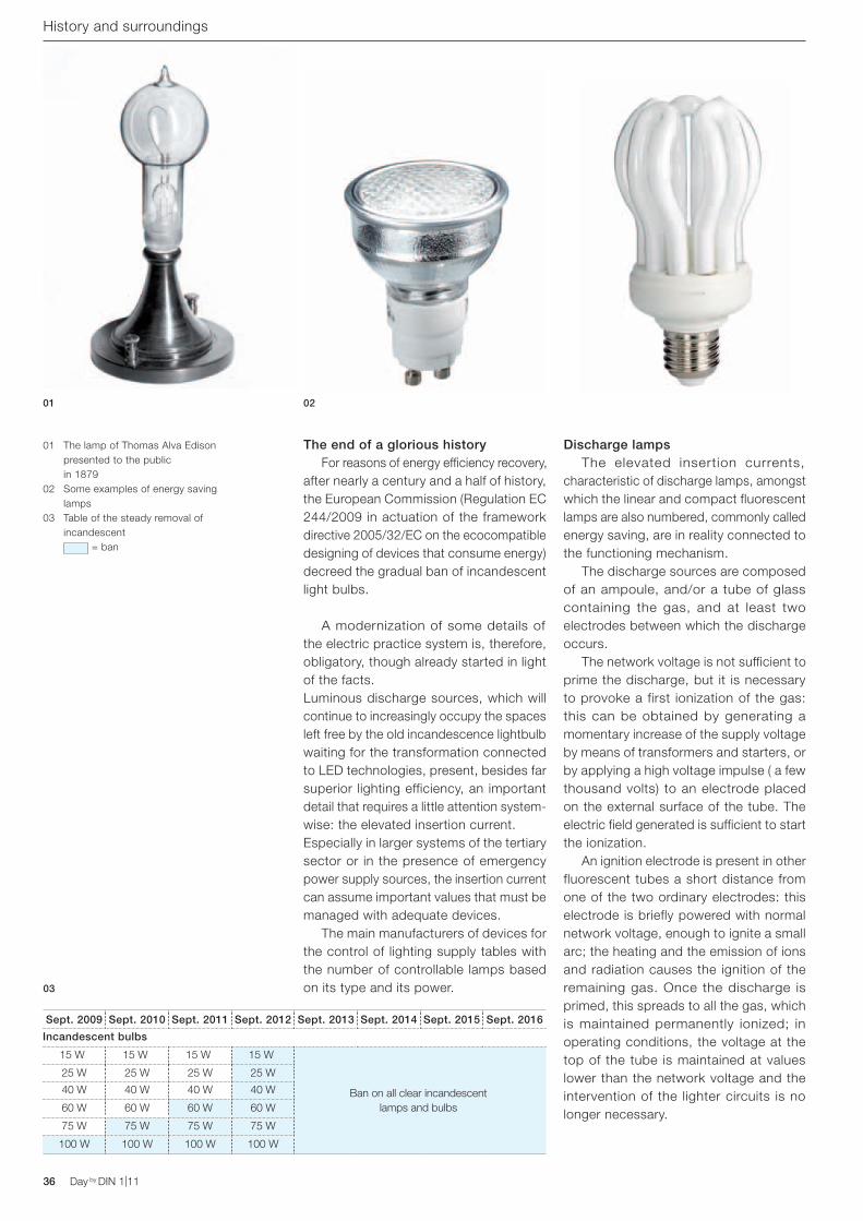
Sept. 2009 Sept. 2010 Sept. 2011 Sept. 2012 Sept. 2013 Sept. 2014 Sept. 2015 Sept. 2016
Incandescent bulbs
15 W 15 W 15 W 15 W
Ban on all clear incandescent lamps and bulbs
25 W 25 W 25 W 25 W
40 W 40 W 40 W 40 W
60 W 60 W 60 W 60 W
75 W 75 W 75 W 75 W
100 W 100 W 100 W 100 W
Discharge lamps The elevated insertion currents, characteristic of discharge lamps, amongst which the linear and compact fluorescent lamps are also numbered, commonly called energy saving, are in reality connected to the functioning mechanism. The discharge sources are composed of an ampoule, and/or a tube of glass containing the gas, and at least two electrodes between which the discharge occurs. The network voltage is not sufficient to prime the discharge, but it is necessary to provoke a first ionization of the gas: this can be obtained by generating a momentary increase of the supply voltage by means of transformers and starters, or by applying a high voltage impulse ( a few thousand volts) to an electrode placed on the external surface of the tube. The electric field generated is sufficient to start the ionization. An ignition electrode is present in other fluorescent tubes a short distance from one of the two ordinary electrodes: this electrode is briefly powered with normal network voltage, enough to ignite a small arc; the heating and the emission of ions and radiation causes the ignition of the remaining gas. Once the discharge is primed, this spreads to all the gas, which is maintained permanently ionized; in operating conditions, the voltage at the top of the tube is maintained at values lower than the network voltage and the intervention of the lighter circuits is no longer necessary.
01 The lamp of Thomas Alva Edison presented to the public in 1879
02 Some examples of energy saving lamps
03 Table of the steady removal of incandescent
= ban
01 02
03
History and surroundings
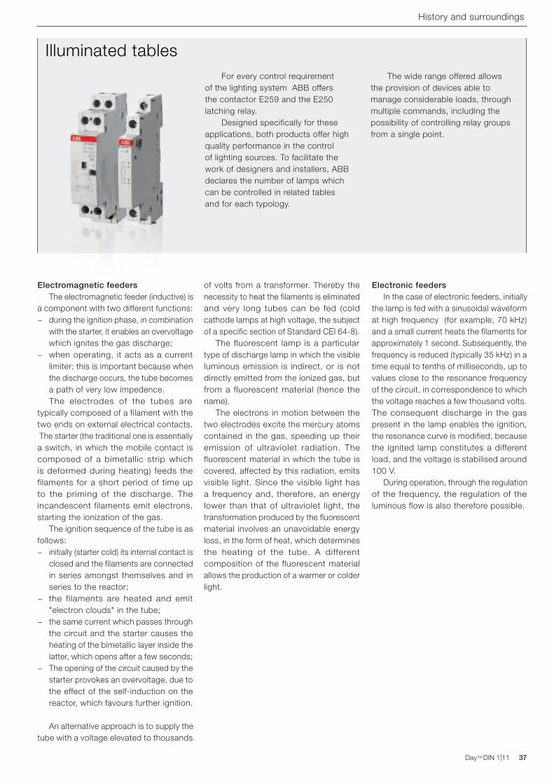
For every control requirement of the lighting system ABB offers the contactor E259 and the E250 latching relay.
Designed specifically for these applications, both products offer high quality performance in the control of lighting sources. To facilitate the work of designers and installers, ABB declares the number of lamps which can be controlled in related tables and for each typology.
The wide range offered allows the provision of devices able to manage considerable loads, through multiple commands, including the possibility of controlling relay groups from a single point.
Illuminated tables
Day by DIN 1|11 37Day by DIN 1|11
Electromagnetic feeders The electromagnetic feeder (inductive) is a component with two different functions:
− during the ignition phase, in combination with the starter, it enables an overvoltage which ignites the gas discharge;
− when operating, it acts as a current limiter; this is important because when the discharge occurs, the tube becomes a path of very low impedence.
The electrodes of the tubes are typically composed of a filament with the two ends on external electrical contacts. The starter (the traditional one is essentially a switch, in which the mobile contact is composed of a bimetallic strip which is deformed during heating) feeds the filaments for a short period of time up to the priming of the discharge. The incandescent filaments emit electrons, starting the ionization of the gas. The ignition sequence of the tube is as follows:
− initially (starter cold) its internal contact is closed and the filaments are connected in series amongst themselves and in series to the reactor;
− the filaments are heated and emit "electron clouds" in the tube;
− the same current which passes through the circuit and the starter causes the heating of the bimetallic layer inside the latter, which opens after a few seconds;
− The opening of the circuit caused by the starter provokes an overvoltage, due to the effect of the self-induction on the reactor, which favours further ignition.
An alternative approach is to supply the tube with a voltage elevated to thousands
of volts from a transformer. Thereby the necessity to heat the filaments is eliminated and very long tubes can be fed (cold cathode lamps at high voltage, the subject of a specific section of Standard CEI 64-8). The fluorescent lamp is a particular type of discharge lamp in which the visible luminous emission is indirect, or is not directly emitted from the ionized gas, but from a fluorescent material (hence the name). The electrons in motion between the two electrodes excite the mercury atoms contained in the gas, speeding up their emission of ultraviolet radiation. The fluorescent material in which the tube is covered, affected by this radiation, emits visible light. Since the visible light has a frequency and, therefore, an energy lower than that of ultraviolet light, the transformation produced by the fluorescent material involves an unavoidable energy loss, in the form of heat, which determines the heating of the tube. A different composition of the fluorescent material allows the production of a warmer or colder light.
Electronic feeders In the case of electronic feeders, initially the lamp is fed with a sinusoidal waveform at high frequency (for example, 70 kHz) and a small current heats the filaments for approximately 1 second. Subsequently, the frequency is reduced (typically 35 kHz) in a time equal to tenths of milliseconds, up to values close to the resonance frequency of the circuit, in correspondence to which the voltage reaches a few thousand volts. The consequent discharge in the gas present in the lamp enables the ignition, the resonance curve is modified, because the ignited lamp constitutes a different load, and the voltage is stabilised around 100 V. During operation, through the regulation of the frequency, the regulation of the luminous flow is also therefore possible.
History and surroundings
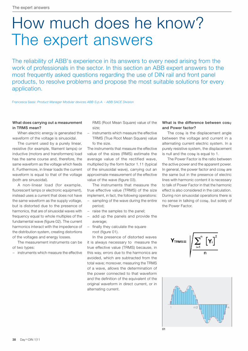
38 Day by DIN 1|11 Day by DIN 1|11
The expert answers
What does carrying out a measurement in TRMS mean? When electric energy is generated the waveform of the voltage is sinusoidal. The current used by a purely linear, resistive (for example, filament lamps) or inductive (motors and transformers) load has the same course and, therefore, the same waveform as the voltage which feeds it. Furthermore, in linear loads the current waveform is equal to that of the voltage (both are sinusoidal). A non-linear load (for example, fluorescent lamps or electronic equipment), instead uses a current that does not have the same waveform as the supply voltage, but is distorted due to the presence of harmonics, that are of sinusoidal waves with frequency equal to whole multiples of the fundamental wave (figure 02). The current harmonics interact with the impedence of the distribution system, creating distortions of the voltages and energy losses. The measurement instruments can be of two types:
− instruments which measure the effective
RMS (Root Mean Square) value of the size;
− instruments which measure the effective TRMS (True Root Mean Square) value fo the size.
The instruments that measure the effective value of the sizes (RMS) estimate the average value of the rectified wave, multiplied by the form factor 1.11 (typical of the sinusoidal wave), carrying out an approximate measurement of the effective value of the wave (figure 03). The instruments that measure the true effective value (TRMS) of the size implement, in fact, the following operations:
− sampling of the wave during the entire period;
− raise the samples to the panel; − add up the panels and provide the
average; − finally they calculate the square
root (figure 01). In the presence of distorted waves it is always necessary to measure the true effective value (TRMS) because, in this way, errors due to the harmonics are avoided, which are subtracted from the total wave; moreover, measuring the TRMS of a wave, allows the determination of the power connected to that waveform and the definition of the equivalent of the original waveform in direct current, or in alternating current.
How much does he know?The expert answersThe reliability of ABB's experience in its answers to every need arising from the work of professionals in the sector. In this section an ABB expert answers to the most frequently asked questions regarding the use of DIN rail and front panel products, to resolve problems and propose the most suitable solutions for every application.
What is the difference between cosj and Power factor? The cosj is the displacement angle between the voltage and current in a alternating current electric system. In a purely resistive system, the displacement is null and the cosj is equal to 1. The Power Factor is the ratio between the active power and the apparent power. In general, the power factor and cosj are the same but in the presence of electric lines with harmonic content it is necessary to talk of Power Factor in that the harmonic effect is also considered in the calculation. During non sinusoidal operations there is no sense in talking of cosj, but solely of the Power Factor.
01
Francesca Sassi: Product Manager Modular devices ABB S.p.A. - ABB SACE Division
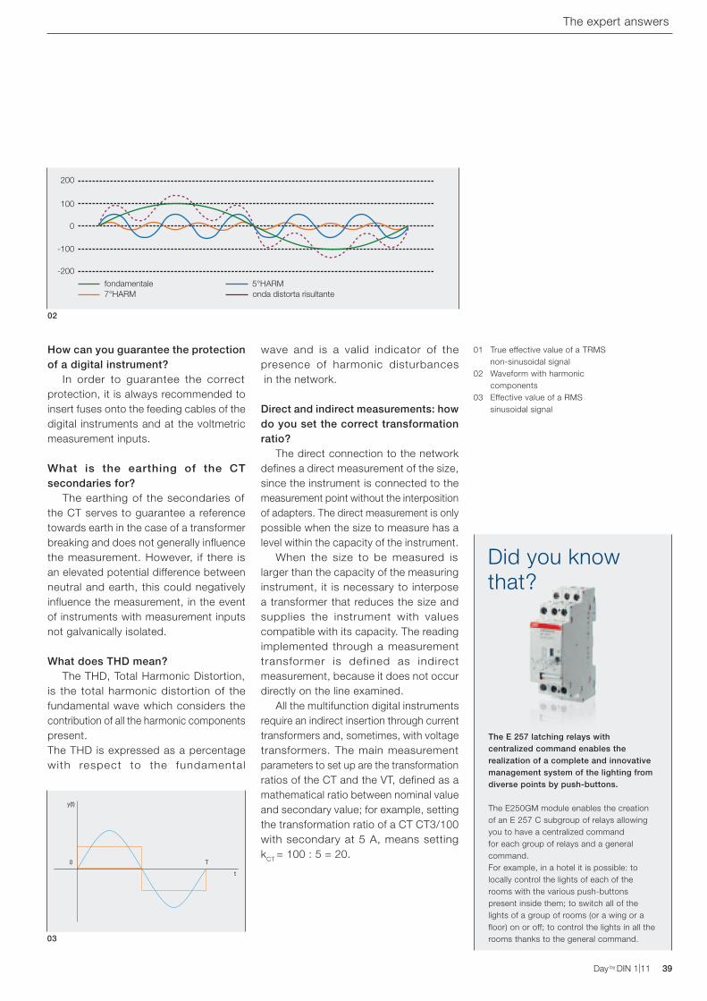
200
100
0
-100
-200
fondamentale7°HARM
5°HARMonda distorta risultante
y(t)
0 T
t
The E 257 latching relays with centralized command enables the realization of a complete and innovative management system of the lighting from diverse points by push-buttons.
The E250GM module enables the creation of an E 257 C subgroup of relays allowing you to have a centralized command for each group of relays and a general command.For example, in a hotel it is possible: to locally control the lights of each of the rooms with the various push-buttons present inside them; to switch all of the lights of a group of rooms (or a wing or a floor) on or off; to control the lights in all the rooms thanks to the general command.
Did you know that?
Day by DIN 1|11 39Day by DIN 1|11
The expert answers
How can you guarantee the protection of a digital instrument? In order to guarantee the correct protection, it is always recommended to insert fuses onto the feeding cables of the digital instruments and at the voltmetric measurement inputs.
What is the earthing of the CT secondaries for? The earthing of the secondaries of the CT serves to guarantee a reference towards earth in the case of a transformer breaking and does not generally influence the measurement. However, if there is an elevated potential difference between neutral and earth, this could negatively influence the measurement, in the event of instruments with measurement inputs not galvanically isolated.
What does THD mean? The THD, Total Harmonic Distortion, is the total harmonic distortion of the fundamental wave which considers the contribution of all the harmonic components present. The THD is expressed as a percentage with respect to the fundamental
wave and is a valid indicator of the presence of harmonic disturbances in the network.
Direct and indirect measurements: how do you set the correct transformation ratio? The direct connection to the network defines a direct measurement of the size, since the instrument is connected to the measurement point without the interposition of adapters. The direct measurement is only possible when the size to measure has a level within the capacity of the instrument. When the size to be measured is larger than the capacity of the measuring instrument, it is necessary to interpose a transformer that reduces the size and supplies the instrument with values compatible with its capacity. The reading implemented through a measurement transformer is defined as indirect measurement, because it does not occur directly on the line examined. All the multifunction digital instruments require an indirect insertion through current transformers and, sometimes, with voltage transformers. The main measurement parameters to set up are the transformation ratios of the CT and the VT, defined as a mathematical ratio between nominal value and secondary value; for example, setting the transformation ratio of a CT CT3/100 with secondary at 5 A, means setting kCT = 100 : 5 = 20.
03
02
01 True effective value of a TRMS non-sinusoidal signal
02 Waveform with harmonic components
03 Effective value of a RMS sinusoidal signal
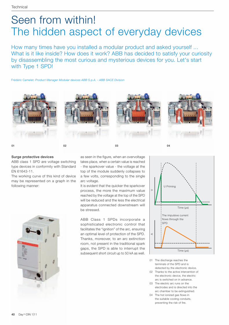
Time (μs)
U Priming
VA
The impulsive current flows through the SPD
Time (μs)
40 Day by DIN 1|11
Technical
Seen from within!The hidden aspect of everyday devices
Frédéric Camelet: Product Manager Modular devices ABB S.p.A. - ABB SACE Division
Surge protective devicesABB class 1 SPD are voltage switching type devices in conformity with Standard EN 61643-11.The working curve of this kind of device may be represented on a graph in the following manner:
as seen in the figure, when an overvoltage takes place, when a certain value is reached - the sparkover value - the voltage at the top of the module suddenly collapses to a few volts, corresponding to the single arc voltage.It is evident that the quicker the sparkover process, the more the maximum value reached by the voltage at the top of the SPD will be reduced and the less the electrical apparatus connected downstream will be stressed.
ABB Class 1 SPDs incorporate a sophisticated electronic control that facilitates the “ignition” of the arc, ensuring an optimal level of protection of the SPD. Thanks, moreover, to an arc extinction room, not present in the traditional spark gaps, the SPD is able to interrupt the subsequent short circuit up to 50 kA as well.
01 The discharge reaches the terminals of the SPD and is detected by the electronic device.
02 Thanks to the active intervention of the electronic device, the electric arc is switched on in advance.
03 The electric arc runs on the electrodes and is directed into the arc chamber to be extinguished.
04 The hot ionized gas flows in the suitable cooling conduits, preventing the risk of fire.
01 02 03 04
How many times have you installed a modular product and asked yourself ... What is it like inside? How does it work? ABB has decided to satisfy your curiosity by disassembling the most curious and mysterious devices for you. Let's start with Type 1 SPD!
Day by DIN 1|11
CT Facile. The choice of current transformers in 3 clicks
ABB SACEA division of ABB S.p.A.Modular DevicesTel. 02 9034.1www.abb.it
With few clicks, CT Facile software allows the pinpointing of a product suitable for the application needed to be carried out, just knowing the characteristics of the main switch.http://www.abb.com/abblibrary/DownloadCenter/ - 2CSC445040E0901
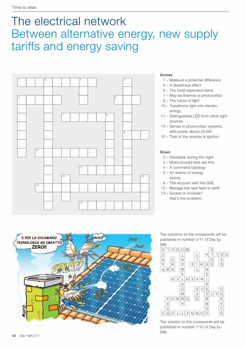
42 Day by DIN 1|11 Day by DIN 1|11
The electrical network Between alternative energy, new supply tariffs and energy saving
Across 1 – Measure a potential difference 5 – A disastrous effect 6 – The most expensive band 7 – May be thermal or photovoltaic 9 – The future of light 10 – Transforms light into electric
energy 11 – Distinguishes LED from other light
sources 14 – Serves in photovoltaic systems
with power above 20 kW 15 – That of the arrester is ignition
Down 2 – Advisable during the night 3 – Multicoloured leds are this 4 – A command typology 5 – An enemy of energy
saving 8 – The account with the GSE 12 – Manage the new feed-in tariff 13 – Socket or modular?
that's the problem!
15
6
16
2
8
9
3
5
10
1
7
13
4
14
11 12
UOE
SR
R
N
O
E
V
N
T
T
T
E
N
E
T
B
DL
R
EM
R
E
O
MC
R
O
R
U
E
P
NMP W TK
TC LT
E S GEA IW E R
OE
O E
ANAS
I
O
QC
SO UD
DNMA
LA
S
OA
NR O SLH
Time to relax
1
5
10
14
2
7
12
3
11
15
8
6
4
9
13
The solutions to the crosswords will be published in number 2/11 of Day by DIN.
The solution to the crosswords will be published in number 1/10 of Day by DIN.
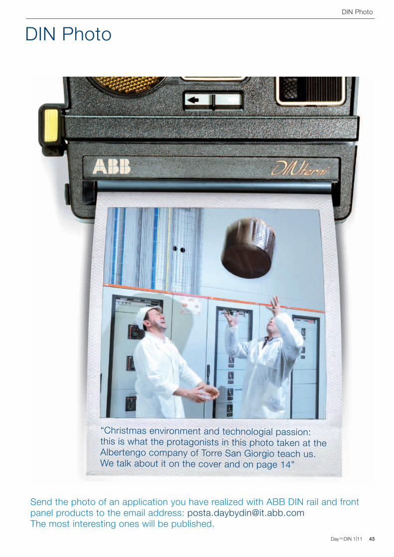
Day by DIN 1|11 43Day by DIN 1|11
DIN Photo
“Christmas environment and technologial passion: this is what the protagonists in this photo taken at the Albertengo company of Torre San Giorgio teach us. We talk about it on the cover and on page 14”
DIN Photo
Send the photo of an application you have realized with ABB DIN rail and front panel products to the email address: [email protected] The most interesting ones will be published.
D Line time switches. Always in time with your needs.
ABB SACEA division of ABB S.p.A.Modular DevicesTel. 02 9034.1www.abb.it
The exclusive design, with back-lit LCD display, and the extreme simplicity of use with a multilanguage menu with two lines of text and only four push-buttons, makes the D Line products ideal in the automation of system functions. Thanks to simple and intuitive programming, D Line time switches allow the easy management of very different commands, from standard ones to those which are cyclical, from count downs to alarms. Equipped with a relay switching at null load, D Line time switches ensure a longer life for the relay and for the load itself. D Line time switches are also able to manage holidays with the possibility of programming for over several years. http://www.abb.com/abblibrary/DownloadCenter/ - 2CSC440021B0901