Embed Size (px)
Citation preview

Proceedings of ASME Turbo Expo 2014: Turbine Technical Conference and ExpositionGT2014
June 16 – 20, 2014, Dusseldorf, Germany
GT2014-26014
AN ACCELERATED MEDIAL OBJECT TRANSFORMATIONFOR WHOLE ENGINE OPTIMISATION
Leran Wang, David J. J. Toal and Andy J. KeaneUniversity of Southampton
Southampton, UKEmail: [email protected]
Felix StanleyRolls-Royce plc.
Derby, UKEmail: [email protected]
ABSTRACTThe following paper proposes an accelerated medial object
transformation for the tip clearance optimisation of whole engineassemblies. A considerable reduction in medial object genera-tion time has been achieved through two different mechanisms.Faces leading to unnecessary branches in the medial mesh areremoved from the model and parallelisation of the medial objectgeneration is improved through the subdivision of the original3D CAD model. The time savings offered by these schemes arepresented with respect to the generation of the medial objects oftwo complex gas turbine engine components. It is also demon-strated that the utilization of these techniques within a designoptimisation may result in a considerable reduction in wall time.
INTRODUCTIONDuring the preliminary design stage, engineers often want
to investigate as many different designs as possible before pro-ceeding to the detailed stage. However, due to the large numberof design variables in a complete engine and the time-consumingnature of 3D finite element simulations, the optimisation of onedesign may take weeks or even months to perform. A 3D fi-nite element mesh typically contains several million degrees-of-freedom (DOF) and one single simulation may take hours or per-haps days to complete [1]. Previous whole engine optimisations,such as those of Toal et al. [2], for example, employed wholeengine transient thermo-mechanical simulations taking severaldays to evaluate even on a high performance compute cluster andresulted in design optimisations taking months to perform. Dueto this time restriction the number of variables included in a de-
sign optimisation tends to be very small which may potentiallylead to a suboptimal design.
Voutchkov et al. [3] took a slightly different approach towhole engine design optimisation by developing a simplifiedshell and beam model of the engine and employing this withina multi-objective evolutionary based design search. The low costof the engine simulations made such an optimisation possible butthe considerable effort in the manual construction of such shelland beam models still makes such an optimisation prohibitivelyexpensive. The model also has no direct link to the 3D geometrymaking it difficult to transfer the optimal shell thicknesses backinto a usable CAD model.
A whole engine design optimisation scheme is therefore re-quired which has the speed of a shell and beam based model butwhich can be directly linked to 3D CAD and is able to representall of the complex features of such a CAD model.
In order to increase the speed of finite element analyses(FEA), dimensional reduction and mixed dimensional modellingtechniques have attracted considerable interest. Thakur et.al [4]published a review paper on current model simplification tech-niques for a variety of purposes among which medial objecttransformation was identified as being an extremely useful di-mensional reduction tool for FEA idealization.
Most existing medial object transformation techniques arebased on the medial axis transform (MAT) [5]. The MAT repre-sents the medial line (in 2D) or the medial surface (in 3D) of agiven 2D surface or 3D solid. Imagine a maximal inscribed discrolling along a surface or a maximal inscribed ball rolling arounda solid, the medial trace and the radius at each medial point formsthe MAT [6] (Fig.1(a)). The MAT is a complete and unique rep-
1 Copyright c© 2014 by Rolls-Royce plc

(a) TRADITIONAL MAT
(b) BRANCH-REDUCED MAT
FIGURE 1. COMPARISON OF TWO MATS
resentation of the original shape and one can regenerate the exactoriginal shape based on the MAT. Once an optimisation has beenperformed using the MAT this relationship can potentially allowthe corresponding solid geometry to be generated.
Rather than perform a complete transformation from theoriginal CAD geometry into a medial object, alternative ap-proaches have also been explored within the literature to createmodels of mixed dimensions with the view to the FEA simula-tions being more accurate than a simulation employing a puremedial object.
The mixed dimensional modelling technique, for example,creates a mixed dimensional idealization from the CAD geome-try. Firstly the geometry is classified into one of three types, thin-sheet, long-slender and complex regions. The identified thin-sheet regions are meshed with shell elements, the long-slenderregions with beam elements and the complex regions with tetra-hedral elements [7–10].
Other similar work within the literature includes the mid-surface generation for non-manifold geometry [11] and the MATbased on identifying face pairs [12, 13].
Unlike most existing MAT techniques which require a solidgeometry as an input, the medial mesh generation process em-ployed in this work only requires a surface triangulation [14] andcalculates the medial mesh based on a surface mesh of the 3D ge-ometry. Whilst the medial mesh resulting from this process canbe directly used for structural analysis, the unique methodologyemployed in its generation allows faces of the original geome-try to be ignored from the process thereby removing unnecessarybranches from the final model and the original geometry to beeasily subdivided to greatly improve parallelisation of the me-dial object generation. Fig.1(b) demonstrates the MAT based ona branch-reduced geometry boundary.
Although not considered within the presented work it shouldalso be recognised that the generated medial mesh can also beused to help construct a high-quality volume mesh [15, 16] forfurther analysis or as part of a multi-fidelity design optimisation[17–19].
FIGURE 2. PROPOSED WHOLE ENGINE OPTIMISATIONWORK FLOW
The accelerated medial object transformation presented inthis paper is a key component within a proposed whole engineoptimisation work flow. The main objective of the optimisationwork flow is to perform tip clearance studies at the preliminarydesign stage. Therefore only casing displacement results are pre-sented in the following sections. However, once a set of designshave been chosen from the optimisation Pareto front, further de-tailed structural analyses could be performed. As shown in Fig.2, the process commences by creating a datum engine model byrevolving a fully-parameterised gas turbine general arrangement(GA) to which 3D components are applied from a library of userdefined features (UDFs). Instead of a traditional 3D finite ele-ment simulation, a 3D medial surface mesh (2D shells) is thenextracted from the 3D geometry. As will be illustrated in thefollowing paper, this process is accelerated by ignoring unneces-sary medial branches and splitting the solid geometry into sev-eral sections. The medial mesh extraction for each section isthen performed in parallel with the separate meshes then com-bined to form the complete medial mesh which can be simulatedusing NASTRAN. As will be demonstrated, carrying out suchsimulations using this mesh offers a considerable reduction insimulation cost with little loss in accuracy.
Although not presented within the current paper, it is pro-posed that the medial mesh simulations are then post-processedand the calculated objective function values employed within asurrogate model based optimisation [20]. Those boxes of Fig. 2highlighted in yellow represent the work presented within thecurrent paper.
The following paper commences with a short discussion ofthe creation of the test case geometry used throughout the re-mainder of the paper. This is followed by a description of pro-cesses by which the proprietary Rolls-Royce medial mesh gener-ation software can be accelerated. The paper then concludes bypresenting the performance of the medial object generation pro-cess and any resulting FEA simulations with respect to two gasturbine engine casings.
2 Copyright c© 2014 by Rolls-Royce plc

FIGURE 3. COMBUSTION CHAMBER OUTER CASING CADMODEL
(a) ISOMETRIC VIEW (b) REAR VIEW
FIGURE 4. COMPRESSOR INTERCASING CAD MODEL
GAS TURBINE TEST CASE GEOMETRIESThe presented work aims to demonstrate the efficiency of
the medial axis generation part of the proposed design optimisa-tion work flow highlighted in Fig. 2. To do so two gas turbineengine casings will be used, a combustion chamber outer casing(CCOC), Fig. 3 and a compressor intercasing, Fig. 4.
Both the CCOC and intercasing geometries are generatedin a similar manner. The portion of the engine general arrange-ment (GA) relating to each section is first parameterised usingSiemens NX. Although not illustrated within the current paper,this parameterisation permits the modification of important fea-tures such as casing thicknesses and flange heights in any fu-ture design optimisation. The parameterised GA is then revolvedto form a solid model to which parametric 3D features are thenadded. The parameters defining the shape of these 3D featurescould also be altered within any future optimisation. Figure 5demonstrates the geometry generation process using the CCOCmodel as an example. A similar process was also used to createthe intercasing model but, as can be clearly seen, this required
FIGURE 5. GEOMETRY GENERATION OF A CCOC
the addition of many more 3D features.While both the CCOC and intercasing models illustrated in
Figures 3 and 4 are somewhat simplified from what would beexpected at the detailed design stage, they are still representativeof the complexity of an actual gas turbine engine. Features whichare important for the structural analysis, such as bosses, holesand struts are included in order to create casing models whichbehave realistically under load.
ACCELERATED MEDIAL MESH GENERATIONThroughout this paper all medial meshes are extracted using
the proprietary, Rolls-Royce, medial mesh generation software,MANTLE (Modelling and Analysis in the Neutral LinE). Fulldetails of the methodology followed by MANTLE in the creationof a medial mesh can be found in the thesis of Stanley [14]1. Thepresented work demonstrates how the preparation of the surfacemesh of the original geometry can accelerate the MANTLE me-dial mesh extraction process.
Before presenting the methodologies for accelerating theprocess let us first consider the medial axis generation itself.Fig.6 uses a 1/12 axisymmetric section of the CCOC to demon-strate the medial mesh extraction process. The inputs to MAN-TLE are the 2D surface meshes (8,152 CTRIA3 elements andeach node has 6 DOFs) of the solid part (Fig.6(a)). BecauseMANTLE has the capability to automatically refine the elementsizes around geometry changes, a coarse surface mesh is suffi-cient to generate a good quality medial mesh. In this particu-lar case an initial element size of 10mm has been used, Fig.6(b)
1Medial mesh generation, patent number GB1300259.7
3 Copyright c© 2014 by Rolls-Royce plc

(a) 1/12 CCOC SECTION (b) GENERATED MEDIAL MESH
FIGURE 6. AN EXAMPLE MEDIAL MESH GENERATION
(a) SURFACE MESHES AREREMOVED FROM HIGHLIGHTEDFACES
(b) BRANCH REDUCED MEDIALMESH
FIGURE 7. GENERATION OF BRANCH REDUCED MEDIALMESH
illustrates the resulting medial mesh which consists of 51,529CTRIA3 shell elements with each element having an indepen-dent thickness value assigned.
In Fig.6(b) it can clearly be observed that the medial meshcontains branches at the top of the flange and at the side of thesection. These branches are generally undesirable because ittakes MANTLE a long time to compute the nodes along themand they add extra mass to the geometry. Unlike most exist-ing medial surface generation tools which require solid geome-try as an input, as MANTLE calculates the medial mesh usingsurface meshes it is possible to reduce the branches in the medialmesh by removing the corresponding surface meshes from theinput (Fig.1(b)). As shown in Fig. 7, if the surface meshes areremoved from the highlighted faces in Fig. 7(a), the generatedmedial mesh will be branch reduced (Fig. 7(b)). The branch-reduced input surface mesh and the generated medial mesh have7,304 and 41,130 CTRIA3 elements respectively, both of whichcontain less elements than the model with branches. As a result,the medial mesh generation time has been reduced by 30% in thisparticular case.
The ability of MANTLE to create such branchless medialmodels also permits the entire process to be easily parallelised.Generally the simpler the geometry model the quicker a medialmesh can be generated. In theory it therefore makes sense to sub-divide a large CAD model into a number of smaller sub-modelswith the medial mesh for each calculated in parallel. This processproves to be complicated using traditional algorithms becausethey have no knowledge of where the splits in the geometry are
and would treat the defining faces of such splits as they wouldany other face in the geometry and create branches.
Figure 6(b) also helps to illustrate this. Here an axisymmet-ric CAD model has been split into 12 identical sub-sections. Butwhen the medial axis is generated branches are included alongthe split faces. Copying this medial mesh around the axis ofthe engine twelve times and combining them into a single meshwould result in ridges along the casing and an incorrect FEA so-lution.
MANTLE’s branchless capability permits the surface meshdefining such splits to be left out of the medial mesh genera-tion process producing the mesh in Fig. 7(b) which can be eas-ily copied around the engine’s axis to produce a correct medialmesh.
Using the same process it is therefore possible to split theoriginal geometry into a series of sub-models and take full ad-vantage of any inherent symmetry within the model. This re-duces the overall medial mesh generation time as a number ofsmaller sections can be run in parallel and also, by taking ad-vantage of any inherent symmetry, fewer medial meshes may berequired. Medial mesh extraction time is therefore dependant onthe largest sub-section plus the time used for combining them.The identification of branchless surfaces and the splitting of thegeometry requires negligible manual effort comparing to the op-timisation work flow as the two processes only need to be carriedout once. In Siemens NX this is done by tagging the appropri-ate faces to be ignored and splitting the solid. It is preferableto split the solid along simple planes rather than to cut throughcomplex geometries because the medial mesh is automaticallyrefined around the split regions and a simpler plane cut will in-troduce fewer additional shell elements. It is also possible to au-tomate both processes using user defined functions (UDFs). Asshown in Fig.1(b) and 7, the branchless medial mesh still reachesthe very end of geometry boundaries, therefore there will be nogaps between adjacent sections. The nodes on the adjacent me-dial mesh edges are aligned automatically by MANTLE which iseasy to achieve because the input surface meshes all have match-ing nodes along the edges.
CASE STUDY 1: CCOCHaving described the proposed methods of accelerating me-
dial mesh generation using MANTLE let us now consider the im-pact of these methods on the two gas turbine casing geometriesdescribed previously. Consider first the CCOC casing presentedin Fig. 3.
Creating a medial mesh of the CCOC geometry in a sin-gle operation and including all faces will take a considerableamount of time, approximately 64 times that taken to generatea 3D tetrahedral mesh (TETRA10 element where each node has3 DOFs) using Siemens NX. However, by reducing the numberof branches in the medial mesh by removing the faces on the tops
4 Copyright c© 2014 by Rolls-Royce plc

(a) INPUT SURFACE MESHES (b) REJOINED MEDIAL MESH
FIGURE 8. CCOC MEDIAL MESH GENERATION BY SPLIT-TING AND REJOINING
TABLE 1. COMPARISON OF MESHING AND SIMULATIONTIMES FOR DIFFERENT CCOC MEDIAL MESH GENERATIONSCHEMES
Full Branch Reduced Split
Relative Mesh Generation Time ×64 ×53 ×18
Relative FE Simulation Time ×0.7 ×0.7 ×0.7
of the flanges and inside the holes illustrated in Fig. 3 reduces thecost of the medial mesh generation by approximately 17% to 53times the cost of creating a 3D tetrahedral mesh.
Let us now consider the impact of parallelising the gener-ation of the same medial mesh. Figure 8 demonstrates the par-allelisation process implemented on the CCOC. In this case thegeometry is split into 7 sections. The two front sections are sym-metric and the five rear sections are axisymmetric. Therefore it isonly necessary to generate the medial meshes for two sections, asshown in Fig.8(a). As required each mesh is mirrored or rotatedand combined to create a complete mesh, (Fig.8(b)). Figure 8(b)also illustrates MANTLE’s automated refinement process, theadditional elements along the splits can be clearly seen. Usingthis parallelised approach the medial mesh extraction time hasbeen further reduced to 18 times that of the 3D tetrahedral mesha 66% increase in efficiency over the baseline approach of cal-culating the complete mesh at once. It should also be noted thatthis 66% improvement includes the same branch reduction pre-viously applied. Table 1 presents a summary of the times takento create the medial mesh for the CCOC relative to create a 3Dtetrahedral mesh.
It is also worth noting that the efficiency increase in walltime does not depend on the whether the geometry has symmetricor axisymmetric properties. As multi-core computers are com-monplace nowadays, the surface mesh can be split into multiplesections and fed into MANTLE in parallel. Exploring symmetricand axis-symmetric properties will, however, save total compu-tational cost.
With a branchless medial mesh of the CCOC obtained let
(a) RIGHT VIEW OF CROSSSECTION
(b) FRONT VIEW
FIGURE 9. LOCATION OF POINTS AROUND CCOC AT WHERETHE DISPLACEMENTS WERE MEASURED
us now consider how it impacts on the speed and accuracy ofany FE simulation. The medial mesh illustrated in Fig. 8(b) istherefore compared directly to a 3D FE simulation employing theunstructured tetrahedral mesh used to define the relative costs ofthe medial mesh generation.
Simulations involving a total of five load cases were set upand carried out using the 3D and medial mesh. In each case, theCCOC is constrained at the rear. Four loads, namely axial, radial,yaw and torque, were applied to the front of the casing while thefifth load case involves a simulation of gravity. The results showthat a simulation using the medial mesh takes 70% of the timerequired to run a 3D simulation. As the medial mesh is almostidentical in all cases, the time savings over the 3D simulation areidentical in Tab. 1.
The displacements for both the full 3D tetrahedral mesh andthe generated medial mesh were measured at five different loca-tions around the CCOC casing, illustrated in Fig.9. Location fivecorresponds to the master node through which the forces for thefirst four load cases are applied. The percentage differences be-tween the 3D simulation and the medial mesh results at each ofthese locations and their maximum and root-mean-square (RMS)values are listed in Tab. 2 for each load case.
Overall there is very little difference in the displacementsbetween the two simulations. Of the five load cases the differ-ence in the displacements at the majority of locations was below6%, well within acceptable bounds. Only the radial load caseappeared to produce errors above this value, but even then themedial simulation was still only 8.26% from the 3D simulation.
As explained during the introduction, during an optimisa-tion process the medial mesh only needs to be generated once ifchanges are made to only the thickness values defining the mesh.In such a case updates to the medial mesh are almost instanta-neous. The 3D FE simulation, however, requires a new mesh tobe generated after every geometry manipulation. This continual
5 Copyright c© 2014 by Rolls-Royce plc
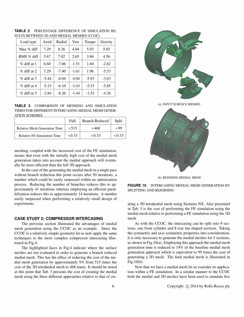
TABLE 2. PERCENTAGE DIFFERENCE OF SIMULATION RE-SULTS BETWEEN 3D AND MEDIAL MESHES (CCOC)
Load type Axial Radial Yaw Torque Gravity
Max % diff 7.29 8.26 4.04 5.93 5.85
RMS % diff 5.67 7.02 2.65 3.86 4.56
% diff at 1 6.60 -7.06 -1.51 1.60 -2.62
% diff at 2 7.29 -7.40 -1.61 1.96 -5.53
% diff at 3 -5.44 -6.04 -4.04 -5.93 -3.63
% diff at 4 -5.15 -6.10 -3.43 -5.53 -5.85
% diff at 5 -2.84 -8.26 -1.44 -1.53 -4.38
TABLE 3. COMPARISON OF MESHING AND SIMULATIONTIMES FOR DIFFERENT INTERCASING MEDIAL MESH GENER-ATION SCHEMES
Full Branch Reduced Split
Relative Mesh Generation Time ×515 ×468 ×99
Relative FE Simulation Time ×0.33 ×0.33 ×0.33
meshing, coupled with the increased cost of the FE simulation,means that even with the initially high cost of the medial meshgeneration taken into account the medial approach will eventu-ally be more efficient than the full 3D approach.
In the case of the generating the medial mesh in a single passwithout branch reduction this point occurs after 50 iterations, anumber which could be easily surpassed within an optimisationprocess. Reducing the number of branches reduces this to ap-proximately 41 iterations whereas employing an efficient paral-lelisation reduces this to approximately 14 iterations. A numbereasily surpassed when performing a relatively small design ofexperiments.
CASE STUDY 2: COMPRESSOR INTERCASINGThe previous section illustrated the advantages of medial
mesh generation using the CCOC as an example. Since theCCOC is a relatively simple geometry let us now apply the sametechniques to the more complex compressor intercasing illus-trated in Fig.4.
The highlighted faces in Fig.4 indicate where the surfacemeshes are not evaluated in order to generate a branch reducedmedial mesh. This has the effect of reducing the cost of the me-dial mesh generation by approximately 9% from 515 times thecost of the 3D tetrahedral mesh to 468 times. It should be notedat this point that Tab. 3 presents the cost of creating the medialmesh using the three different approaches relative to that of cre-
(a) INPUT SURFACE MESHES
(b) REJOINED MEDIAL MESH
FIGURE 10. INTERCASING MEDIAL MESH GENERATION BYSPLITTING AND REJOINING
ating a 3D tetrahedral mesh using Siemens NX. Also presentedin Tab. 3 is the cost of performing the FE simulation using themedial mesh relative to performing a FE simulation using the 3Dmesh.
As with the CCOC, the intercasing can be split into 9 sec-tions, one front cylinder and 8 rear fan-shaped sections. Takingthe symmetric and axis-symmetric properties into consideration,it is only necessary to generate the medial meshes for 5 sections,as shown in Fig.10(a). Employing this approach the medial meshgeneration time is reduced to 19% of the baseline medial meshgeneration approach which is equivalent to 99 times the cost ofgenerating a 3D mesh. The final medial mesh is illustrated inFig.10(b).
Now that we have a medial mesh let us consider its applica-tion within a FE simulation. In a similar manner to the CCOCboth the medial and 3D meshes have been used to simulate five
6 Copyright c© 2014 by Rolls-Royce plc

(a) RIGHT VIEW OF CROSSSECTION
(b) FRONT VIEW
FIGURE 11. LOCATION OF POINTS AROUND INTERCASINGWHERE DISPLACEMENTS ARE MEASURED
load cases. In each case, the intercasing is constrained at the rearwith axial, radial, yaw and torque loads applied at the front of thecasing. As with the CCOC the fifth load case considers the actionof gravity. As per the CCOC above a global mesh size of 5mmwas used to construct the 3D mesh. In this case a simulation ofthe intercasing using the medial mesh is approximately 33% ofthe cost of a fully 3D simulation. Even with the initial expenseof the medial mesh generation this large reduction in simulationtime means that an optimisation employing the medial approachonly requires 20 iterations to become more efficient that the 3DFE approach.
Given the reduction in relative simulation cost compared tothe full 3D simulation as the complexity of the 3D geometry in-creased from the CCOC to the intercasing, one would expect amedial mesh based simulation of an entire engine to be extremelyefficient. Likewise given the modular design of a modern gasturbine engine and the presence of multiple symmetric featuresone would expect the medial mesh generation to be very paral-lelisable. The presented technology therefore has the potentialto offer huge performance gains when applied to a whole engineassembly.
The results of these simulations are compared at 14 differentlocations around the intercasing, illustrated in Fig.11. The per-centage differences at these points between the two simulationsand the maximum and RMS values are listed in Table 4.
As with the CCOC the results of the medial mesh simulationare quite close to those of the 3D simulation. In the worst case themedial mesh simulation is 10.36% away from the 3D simulationbut, on average for each load case, the simulations are within lessthan 8%.
TABLE 4. PERCENTAGE DIFFERENCE OF SIMULATION RE-SULTS BETWEEN 3D AND MEDIAL MESHES (INTERCASING)
Load type Axial Radial Yaw Torque Gravity
Max % diff 10.34 7.29 7.61 9.20 10.36
RMS % diff 6.69 4.91 5.00 7.83 7.44
% diff at 1 7.54 -5.61 -4.10 -5.35 -9.37
% diff at 2 -3.20 -5.04 -4.84 -6.67 -9.11
% diff at 3 -5.99 -5.97 -4.65 -9.16 -8.45
% diff at 4 -6.04 -5.42 3.53 -9.17 -7.90
% diff at 5 -6.08 -3.13 -5.55 -7.79 -5.53
% diff at 6 -7.95 -5.45 -5.87 -8.70 -8.27
% diff at 7 -7.30 -4.95 -5.99 -8.70 -4.66
% diff at 8 -10.23 -7.11 -5.83 -9.12 2.20
% diff at 9 -10.34 -7.29 -6.28 -9.05 10.36
% diff at 10 1.97 -2.61 -1.56 -4.52 -5.20
% diff at 11 -3.25 -1.78 -1.65 -5.44 -5.21
% diff at 12 1.07 0.00 3.13 -9.20 -7.81
% diff at 13 -3.57 -1.18 -5.35 -8.24 -9.21
% diff at 14 -9.69 -6.04 -7.61 6.13 -6.20
CONCLUSIONSThis paper presents the authors’ efforts to reduce the cost of
medial object generation through branch removal and paralleli-sation as part of the development of an efficient whole engine de-sign optimisation framework. Employing these approaches it hasbeen demonstrated that a medial mesh based simulation is fasterthan a traditional 3D simulation with comparable accuracy. Foran optimisation of more than 20 iterations employing a medialmesh based process will be more efficient than 3D simulations,even with the overhead of generating the medial mesh. Giventhe potential number of design variables in a simple componentlike a CCOC, an optimisation would easily exceed this numberof iterations. An optimisation of the presented intercasing geom-etry, employing 100 iterations would be completed in less thanhalf the time of the equivalent optimisation employing 3D sim-ulations. This efficiency gain is expected to continue to growfurther if larger whole engine assemblies were to be consideredin the future.
Whilst the presented work has focused on geometry prepa-ration and medial mesh generation, future work will embed itwithin a surrogate model based optimisation.
7 Copyright c© 2014 by Rolls-Royce plc

ACKNOWLEDGMENTThe research leading to these results has received fund-
ing from the European Community’s Seventh Framework Pro-gramme (FP7/2007-2013) under grant agreement NO. 314366.The authors also acknowledge Rolls-Royce for granting permis-sion to publish this paper.
REFERENCES[1] Benito, D., Dixon, J., and Metherell, P., June 9-13, 2008.
“3D thermo-mechanical modelling method to predict com-pressor local tip running clearances”. In Proceedings ofASME Turbo Expo 2008: Power for Land, Sea, and Air,pp. 1589–1598.
[2] Toal, D., Keane, A., Benito, D., Dixon, J., Yang, J.,Price, M., Robinson, T., Remouchamps, A., and Kill,N., 2013. “Multi-fidelity multidisciplinary whole en-gine thermo-mechanical design optimization”. Journal ofPropulsion and Power, (Under Review).
[3] Voutchkov, I., Keane, A., and Fox, R., 2006. “Robuststructural design of a simplified jet engine using multiob-jective optimization”. In 11th AIAA/ISSMO Multidisci-plinary Analysis and Optimization Conference.
[4] Thakur, A., Banerjee, A., and Gupta, S., 2009. “A surveyof cad model simplification techniques for physics-basedsimulation applications”. Computer-Aided Design, 41(2),p. 6580.
[5] Blum, H., 1967. A transformation for extracting new de-scriptors of shape. MIT Press, Cambridge, MA, pp. 362–380.
[6] Robinson, T., Armstrong, C., Lee, K.-Y., and Ou, H., 6-8 June, 2006. “Automated mixed dimensional modellingfor the finite element analysis of swept and revolved cadfeatures”. In Proceedings of the 2006 ACM symposium onSolid and physical modelling, p. 117128.
[7] Robinson, T., Armstrong, C., Lee, K.-Y., and Ou, H., 21-22 March, 2005. “Automatic mixed dimensional finite ele-ment modelling of sketch based cad components”. In 13thACME CONFERENCE.
[8] Robinson, T., Fairey, R., Armstrong, C., Ou, H., and Butlin,G., October 1215, 2008. “Automated mixed dimensionalmodelling with the medial object”. In Proceedings of the17th International Meshing Roundtable, pp. 281–298.
[9] Robinson, T., Armstrong, C., and Fairey, R., 2011. “Auto-mated mixed dimensional modelling from 2D and 3D CADmodels”. Finite Elements in Analysis and Design, 47(2),p. 151165.
[10] Nolan, D., Tierney, C., Armstrong, C., Robinson, T., andMakem, J., 2013. “Automatic dimensional reduction andmeshing of stiffened thin-wall structures”. EngineeringWith Computers.
[11] Chong, C., Kumarb, A., and Lee, K., 2004. “Auto-
matic solid decomposition and reduction for non-manifoldgeometric model generation”. Computer-Aided Design,36(13), p. 13571369.
[12] Ramanathan, M., and Gurumoorthy, B., 2003. “Construct-ing medial axis transform of planar domains with curvedboundaries”. Computer-Aided Design, 35(7), p. 619632.
[13] Yin, L., Luo, X., and Shephard, M., September 11-14,2005. “Identifying and meshing thin sections of 3-d curveddomains”. In Proceedings of the 14th International Mesh-ing Roundtable, pp. 33–54.
[14] Stanley, F., 2010. “Dimensional reduction and design op-timization of gas turbine engine casings for tip clearancestudies”. Doctoral Thesis, Univeristy of Southampton,Southampton, UK.
[15] Sampl, P., 2001. “Medial axis construction in three dimen-sions and its application to mesh generation”. EngineeringWith Computers, 17(3), pp. 234–248.
[16] Makem, J., Armstrong, C., and Robinson, T., 2012. “Auto-matic decomposition and efficient semi-structured meshingof complex solids”. Engineering with Computers.
[17] Forrester, A., Sobester, A., and Keane, A., 2007. “Multi-fidelity optimization via surrogate modelling”. Proceedingsof the Royal Society A, 463(2088), pp. 3251–3269.
[18] Brooks, C., Forrester, A., Keane, A., and Shahpar, S., 2011.“Multi-fidelity design optimisation of a transonic compres-sor rotor”. In 9th European Turbomachinery Conference,Istanbul, Turkey, 21st-25th March.
[19] Toal, D., and Keane, A., 2011. “Efficient multi-point aero-dynamic design optimization via co-kriging”. Journal ofAircraft, 48(5), pp. 1685–1695.
[20] Forrester, A., Sobester, A., and Keane, A., 2008. Engineer-ing Design via Surrogate Modelling: A Practical Guide.John Wiley & Sons, Ltd, Chichester, UK.
8 Copyright c© 2014 by Rolls-Royce plc