Embed Size (px)
Citation preview

An Adaptive Speed Control Approach for DC Shunt Motors
Authors:
Ruben Tapia-Olvera, Francisco Beltran-Carbajal, Omar Aguilar-Mejia, Antonio Valderrabano-Gonzalez
Date Submitted: 2019-02-05
Keywords: neural networks, model-free control, adaptive speed control, DC shunt motors
Abstract:
A B-spline neural networks-based adaptive control technique for angular speed reference trajectory tracking tasks with highly efficientperformance for direct current shunt motors is proposed. A methodology for adaptive control and its proper training procedure areintroduced. This algorithm sets the control signal without using a detailed mathematical model nor exact values of the parameters ofthe nonlinear dynamic system. The proposed robust adaptive tracking control scheme only requires measurements of the velocityoutput signal. Thus, real-time measurements or estimations of acceleration, current and disturbance signals are avoided. Experimentalresults confirm the efficient and robust performance of the proposed control approach for highly demanding motor operation conditionsexposed to variable-speed reference trajectories and completely unknown load torque. Hence, laboratory experimental tests on adirect current shunt motor prove the viability of the proposed adaptive output feedback trajectory tracking control approach.
Record Type: Published Article
Submitted To: LAPSE (Living Archive for Process Systems Engineering)
Citation (overall record, always the latest version): LAPSE:2019.0267Citation (this specific file, latest version): LAPSE:2019.0267-1Citation (this specific file, this version): LAPSE:2019.0267-1v1
DOI of Published Version: https://doi.org/10.3390/en9110961
License: Creative Commons Attribution 4.0 International (CC BY 4.0)
Powered by TCPDF (www.tcpdf.org)

Article
An Adaptive Speed Control Approach for DCShunt MotorsRuben Tapia-Olvera 1, Francisco Beltran-Carbajal 2, Omar Aguilar-Mejia 3
and Antonio Valderrabano-Gonzalez 4,*1 Departamento de Ingeniería Eléctrica, Universidad Nacional Autónoma de México, Av. Universidad 3000,
Cd. Universitaria, Delegación Coyoacán, C.P. 04510 Mexico City, Mexico; [email protected] Departamento de Energía, Universidad Autónoma Metropolitana, Unidad Azcapotzalco, Av. San Pablo
No. 180, Col. Reynosa Tamaulipas, C.P. 02200 Mexico City, Mexico; [email protected] Departamento de Ingeniería, Universidad Politécnica de Tulancingo, Ingenierías No. 100. Col. Huapalcalco,
C.P. 43629 Tulancingo, Mexico; [email protected] Facultad de Ingeniería, Universidad Panamericana (Campus Guadalajara), Prolongación Calzada
Circunvalación Poniente 49, C.P. 45010 Zapopan, Mexico* Correspondence: [email protected]; Tel.: +52-33-1368-2200 (ext. 4244)
Academic Editor: Chunhua LiuReceived: 2 July 2016; Accepted: 8 November 2016; Published: 17 November 2016
Abstract: A B-spline neural networks-based adaptive control technique for angular speed referencetrajectory tracking tasks with highly efficient performance for direct current shunt motors is proposed.A methodology for adaptive control and its proper training procedure are introduced. This algorithmsets the control signal without using a detailed mathematical model nor exact values of the parametersof the nonlinear dynamic system. The proposed robust adaptive tracking control scheme onlyrequires measurements of the velocity output signal. Thus, real-time measurements or estimations ofacceleration, current and disturbance signals are avoided. Experimental results confirm the efficientand robust performance of the proposed control approach for highly demanding motor operationconditions exposed to variable-speed reference trajectories and completely unknown load torque.Hence, laboratory experimental tests on a direct current shunt motor prove the viability of theproposed adaptive output feedback trajectory tracking control approach.
Keywords: DC shunt motors; adaptive speed control; model-free control; neural networks
1. Introduction
Electrical machines are part of a wide variety of applications for use from domestic and industrialto remote research applications on land, air, water, and finally in space, each one with its owncharacteristics and specific protections [1]. Modern systems are complex, and new approaches inelectric motor control are demanded, having high-precision requirements of speed and position undervariable load torque. Consequently, it is necessary to develop new proposals for control and protectionof electric motors [2,3].
Although direct current (DC) machines have been widely studied, there are still many possibilitiesfor their use as motors and generators [4]. An open research topic about DC shunt motor control isaddressed to achieve a highly efficient and robust performance by using measurements of the outputsignal to be controlled. In fact, it is widely known that energy efficiency is related to operation costs.Certainly, this problem is quite challenging when some detailed mathematical model of the nonlineardynamic system exposed to time-varying disturbances is not available. Moreover, in several practicalengineering applications, the exact values of the system parameters are also unavailable. Thus, controlpolicies for electric motors installed in industrial plants should be performed by using measurementsof the output signal and a single voltage input.
Energies 2016, 9, 961; doi:10.3390/en9110961 www.mdpi.com/journal/energies

Energies 2016, 9, 961 2 of 16
On the other hand, speed reference trajectory tracking controllers for motors based onefficient motion planning could demand measurements of several state variables, increasing controlimplementation costs. Therefore, motors must demonstrate a satisfactory performance in a wide rangeof operating conditions and adaptability characteristics to face the changing demands of the loadtorque and environmental conditions. For instance, DC motors are used in many areas such as mobilerobotics, industrial robotic arms, electric vehicles, elevators, cranes and drills, which demand variableoperating conditions.
Diverse control approaches have been reported in the literature for electric motors. Robustness andan acceptable transient response for the practical closed-loop system are some relevant main objectivesto be considered in the controller synthesis. However, those control performance requirements arestill an open and challenging research problem for scenarios where a detailed mathematical modeland accurate values of the system parameters are unavailable, and a minimal (optimal) number ofsensors and actuators is preferred for reduction of implementation costs. Moreover, a nonlineardynamic system could be subjected to unknown endogenous and exogenous disturbances affectingthe performance indicators specified for the system response. There are several controllers basedon sliding modes [2], predictive control [4], conventional proportional-integral-derivative (PID)techniques [5–8], robust control [9], neural networks [1,10], and fuzzy logic [11]. Some relevantaspects of these contributions are described in the next paragraphs. Nevertheless, most of themrequire full or partial information of the mathematical model and motor parameters, limiting theirapplication because controllers are depending on the availability of these values [4,10,11]. Motors aselectric actuators are employed in many practical engineering systems; therefore, obtaining thisinformation is an additional task, and it is possible that the controller performance could be degraded.Moreover, some of them have a high computational cost which could restrict their operation forreal time applications [10]. For instance, radial basis function neural networks are formed bythree layers (input-hidden-output), and the number of neurons in each layer is also an importantissue for correct performance. This fact increases the number of calculations to obtain a desiredperformance; furthermore, an offline learning rule may be necessary due to the amount of systemdata required for the training process. These aspects restrict the training stage and include a widerrange of operating conditions. For B-spline neural networks, only a layer is required and an on-linelearning rule is used. The number of computational calculations is based on basic operations (sum,subtraction, multiplication) with a smaller number of layers and neurons. In addition, only theevaluation of two basis functions is necessary. Therefore, B-spline neural networks qualify as anadequate option to be applied in the synthesis of some adaptive and robust tracking control schemewith low computational costs.
Speed control of a DC motor with known input delay and unknown disturbances is presentedin [4]. Controllers based on a predictive technique are used to obtain a satisfactory performance inthe presence of disturbances. A simplified transfer function of the DC motor with a retarded inputis employed for design purposes. Experimental and simulation studies are included to show theintroduced controller performance. In [5], a fractional-order technique is integrated into PI/PIDlinear controllers as a method to enhance their performance. The controller behavior is shownby a DC motor system where its dynamics are described by a conventional first-order model plusdead time. Here, simulation and experimental results are also presented. Ref. [9] combines robustdesign with robust control and presents results of the coupling between them. An objective functionbased on these two concepts in the presence of uncertainty is proposed. Moreover, simulationresults are exhibited for design performance evaluation. In particular, the analysis and design ofDC motor controllers is emphasized for so-called direct current permanent magnet, or separateexcitation, reaching simple linear models, and justifying its performance against certain operatingconditions [4,8,10,11]. Its operation is guaranteed around some equilibrium point and is also highlydependent on the knowledge of the motor parameters. In this configuration, the inrush current is onlylimited by the armature resistance, which is relatively high for small motors and, thus, there are no

Energies 2016, 9, 961 3 of 16
large current problems. However, for motors of several electric powers, the armature resistance is small,and then an excessively high armature current is present in a starter condition at rated voltage [12].Therefore, a starter resistor is connected in series to the armature winding, causing losses and the needto include and turn off starting resistors.
The use of adaptive control algorithms offers an attractive alternative for speed tracking of DCmotors [10,11,13,14]. A direct adaptive fuzzy logic controller is exposed in [11]; it is estimated fromtwo levels—one uses a Mamdani fuzzy controller and the other is an inverse model based on aTakagi–Sugeno method. Experimental results validate the controller behavior. In [10], an adaptiveneural controller for the tracking problem of a DC motor is presented. The neural networks are usedto estimate the unknown functions included in the systems. The state variables of the DC motorare required to be constrained in the compact set in controller design procedure. Simulation resultsvalidate the stability analysis of the design.
The DC shunt motor configuration discussed in this paper considers its nonlinear dynamics,which makes the design of some robust speed control scheme a non-simple task [12]. In this paper,robustness is considered against parametric uncertainty and disturbances due to variable load torque.Thus, conventional linear speed controllers could not be sufficient to suitably regulate some motorfor a wide range of possible uncertain operating conditions. This motor configuration intends thatthe change in the mechanical load torque from zero to full value induces a minimal impact on therotor speed, including sudden changes over time. Since DC shunt motors have wide applicability,it is required to expand the existing studies with the inclusion of adaptive control techniques tocover highly demanding conditions, to which the motor could be exposed. Hence, the efficient androbust control of electric motors using a minimum number of sensors is a challenging, relevant andpertinent research topic, and its solutions admit a wide variety of real applications in the developmentof engineering products and systems.
On the other hand, artificial neural networks (ANN) are able to model and control nonlinear andnon-stationary systems on-line. The nature of this technique makes the controller robust, adaptive andoptimal for use in independent or hybrid configurations with existing techniques. These featuresoffer an important option to practicing engineers facing uncertain changes in physical systems andhigh demands of connected loads. ANN are particularly attractive for controlling electric motors.At the same time, they consider the complexity of the physical system and provide a realistic controlwith less computational time for an efficient and robust control in a wide operating range. In thisregard, B-spline neural networks (BSNN) are a particular class of neural networks that have exhibitedimportant results in various practical physical systems [15–20]. This paper presents the design andperformance assessment of an adaptive tracking control approach based on B-spline neural networkswith the capabilities required for real-time applications of DC shunt motors, without requiringa detailed mathematical model and values of the parameters of the nonlinear dynamic system.The results exhibit its ability to adapt and face changes in motor speed conditions and variableload torque disturbance inputs. The proposed controller shows that only a previous off-line trainingfor some operating conditions is required and based on weights updating together with the basefunctions shape, it adapts to changes in the original design without losing its high performance.The result is an adaptive and robust control scheme that enhances the motor operation even inoperating conditions different to where the design was done. In the present study, a high trackingperformance refers to achieving small deviations from the speed reference trajectory planned forthe closed-loop motor dynamics, in spite of endogenous and exogenous disturbances due to loadtorque and system parameters which are assumed to be unknown. Moreover, the proposed trackingcontrol scheme only requires measurements of the speed output signal. Real-time measurements orestimations of acceleration, current and disturbance signals are then avoided. Experimental resultsconfirm the effectiveness of the proposed control approach for highly demanding motor operationconditions subjected to variable speed reference trajectories and completely unknown load torque.

Energies 2016, 9, 961 4 of 16
Therefore, laboratory experimental tests on a DC shunt motor prove the viability of the proposedadaptive output feedback trajectory tracking control approach.
2. DC Shunt Motor Model
There are various configurations of DC motors, where one in particular provides importantoperating characteristics where the rotor speed does not change appreciably as the load torque variesfrom zero to its nominal value [12]. Figure 1 shows a connection diagram of the motor under thepresent study.
Figure 1. Equivalent circuit of a direct current shunt motor.
In this figure, we can distinguish in the field winding the following elements: L f is the fieldwinding inductance, r f is the field resistance, r f x is an external variable resistance, i f is the fieldcurrent, and u f is the field voltage. In the armature winding, the elements available are: La is thearmature winding inductance, Ra is the armature resistance, ia is the armature current, and ua is thearmature voltage. La f is the mutual winding inductance and ω is the rotor speed.
We can see that the voltage source supplies both the field winding and the armature winding;therefore, the total current it is the sum of the two circulating currents it = ia + i f . Considering thevoltage-current relation for resistive and inductive elements, and grouping the field resistive elementsin R f = r f x + r f , the DC motor model is obtained as
L fddt
i f = −R f i f + u f , (1)
Laddt
ia = −Raia − La f i f ω + ua. (2)
The relationship among electrical and mechanical systems is determined by
Jddt
ω = −bω + La f i f ia − τL, (3)
where J is the moment of inertia of the rotor, b is the viscous damping coefficient, and τL is theload torque. Here, the electric torque is τe = La f i f ia. The mathematical model exhibits a couplednonlinear dynamic system. Therefore, conventional linear controllers can only guarantee a satisfactoryoperation around a certain equilibrium point. From the mathematical model, the equilibrium points ofthe system can be determined as
i f =uinR f
, (4)
ia =
(bR2
f + R f La f τL
)u
inL2
a f u2in + bRaR2
f, (5)
ω =−RaR2
f τL + La f R f u2in
L2a f u2
in + bRaR2f
, (6)

Energies 2016, 9, 961 5 of 16
where uin = ua = u f . It can be seen that the equilibrium points depend on the voltage applied onterminals, the load torque and motor parameters. Therefore, the motor has multiple equilibrium pointsdepending precisely on the desired operating condition.
3. Control Design Approaches Based on the Mathematical Model
In this section, two conventional control design methodologies based on the use of somemathematical models of the dynamic system are described in order to show the main differences ofthe robust adaptive control approach proposed in this paper. The first control method is based on alinear mathematical model. Hence, the linear controller is only valid around some specific equilibriumoperation point. The second control method is based on sliding modes that consider a mathematicalmodel of the system that is available. Moreover, some values of the system parameters are required forcontroller implementation. In spite of good performance indicators of both control design methods,the use of some mathematical model and the knowledge of system parameters could be a relevantlimitation for the implementation of several nonlinear control techniques in real shunt electric motors.
Therefore, the proposed adaptive control approach represents a very good alternative choice forspeed reference trajectory tracking tasks planned for DC shunt electric motors subjected to disturbancesdue to system uncertainty and completely unknown variable load torque. Thus, the use of a detailednonlinear mathematical model of the dynamic system, a priori knowledge of exact values of machineparameters and real-time measurements or estimation of acceleration, current and load torque becomeunnecessary in our robust control approach based on B-spline neural networks.
3.1. Linear Controller Design
The linear model representation can be obtained by small signal analysis around an equilibriumpoint, defining x1 = i f , x2 = ia, x3 = ω, the linearized form of Equations (1)–(3) are given by
∆x = A ∆x + B ∆um, (7)
∆y = C ∆x + D ∆um, (8)
where um1 = uin and um2 = τL are the control and torque inputs, respectively, of the DC motor, and
A =
∂ f1∂x1
∂ f1∂x2
∂ f1∂x3
∂ f2∂x1
∂ f2∂x2
∂ f2∂x3
∂ f3∂x1
∂ f3∂x2
∂ f3∂x3
, B =
∂ f1
∂um1
∂ f1∂um2
∂ f2∂um1
∂ f2∂um2
∂ f3∂um1
∂ f3∂um2
,
C =[
0 0 1]
, D = 0,
where f1, f2 and f3 are related to the nonlinear model described by Equations (1)–(3).The above partial derivatives are evaluated at the equilibrium point about which the small
perturbation is being analyzed. Around this operating condition, some linear control scheme canbe easily designed from basic control fundamentals. Therefore, satisfactory velocity regulation canbe guaranteed in a small neighborhood operation where the system dynamics can be convenientlyapproximated by the linear mathematical model.
Notice that eigenvalues of the linearized system model depend on the motor parameters andoperating conditions. Thus, system poles are moving in the complex plane depending on the operatingconditions of the machine. Hence, the system damping and natural frequency could be changed inseveral manners. There are different ways for tuning a linear controller. From this representation,it is clear that controller gains and time constants are dependent on motor operating conditions.In any case, an acceptable and stable controller performance can only be guaranteed around a specificequilibrium point.

Energies 2016, 9, 961 6 of 16
3.2. Super-Twisting Sliding Mode Control Design
In this subsection, a modern control approach based on sliding modes is described. In fact,the sliding mode control methodology is quite known due to the controller robustness with respect toparametric uncertainty and exogenous disturbances. Interested readers are referred to the excellentbook about sliding mode control [21].
First of all, the speed tracking error variable is defined as: e = ωd −ω, where ωd is the referenceshaft speed. To design a controller, we define the state variables as: z1 = e and z2 = e. A controlalgorithm for the DC shunt motor based on second order sliding modes can be proposed as follows:
uin = −u1
√|s|sign (s) + v, (9)
v = −u2sign (s) , (10)
with u1 > 0, u2 > 0 and s = kz1 + z1, where k > 0 is the controller gain. Note that the sliding surface salso demands measurements of the acceleration signal.
Differentiating s with respect to time and considering Equations (9) and (10), the dynamics of thesliding variable is given by
dz1
dt= z2, (11)
dz2
dt= −b1z1 − b1z2 + φ (t)− cuau f , (12)
where b1 = b/J, c = La f /JL f La, and φ is defined as
φ (t) = ωd + ωd +τLJ+
τLJ− b2i f ia − b3i2f ω− b4u f ia − b5i f ωu f , (13)
where bi, i = 2, . . . , 5 are constants, depending on the uncertain motor parameters. The system motionin sliding mode is independent of parameters bi, c and disturbances in φ. The Lyapunov function todetermine the stability of the proposed system is given by [21]
V = 2
√12
s2 + M |s|. (14)
The stability proof consists of a time derivative of the Lyapunov function and second derivativeof s to make an evaluation of the uncertainty behavior, on the basis of which can be shown that theuncertain state trajectory in the plane twists around the origin converging to it in finite time as in [22].
The super-twisting sliding mode controller implementation is done by simultaneously solvingEquations (9)–(13) in each sample time and the actual rotor speed must be available. To improve theinput voltage, a low pass filter can be included in the control signal, and another alternative is bymeans of the concept of equivalent control. In this case, all motor parameters are required.
4. Proposed Adaptive B-Spline Controller Design
Considering the nonlinear nature of DC motors described in section two and a linear controller,a problem arises with the regulation of the interest variables. If it is possible, the control law must geta driver that is robust, even tracking speed trajectories over time. A number of neural networks-basedstructures have been developed to improve the system robustness. B-spline has been used for solvinga great deal of mathematical and practical problems, demonstrating fast and precise results [18–20].In that sense, in this work, an adaptive controller based on B-spline neural networks is proposed.Its design consists of two stages: first in defining the structure and characteristics of the inputs and thetraining rule; the second part is an on-line learning where the ANN by itself can determine changes inthe reference signal, load torque and motor parameters.

Energies 2016, 9, 961 7 of 16
There are several examples where the conventional techniques are changed or improved withadaptive algorithms in different applications fields. In [20], neural networks training is presentedwith an on-line procedure for power electronic applications. Figure 2 presents the B-spline neuralnetwork structure where only a layer with two basis functions is necessary; this is the basic conceptto understand the adaptive scheme requirements. This structure consists of an input space, a layerformed with basis functions output and a weight vector and the BSNN output. Some parametershave to be specified, such as inputs, the number and shape of basis functions and the learning rate;however, once the BSNN is specified, it achieves a good performance over wide range of operatingconditions. We defined these features in an off-line stage, where the performance is verified by collecteddata of the DC shunt motor. The adaptive controller has the same form that is showed in Figure 2:(1) an input (error between actual and reference speed); (2) two basis functions of three orders that havethe same form that is exhibited in Figure 2, and it is considered that the input signal is normalized;(3) two weights that are updating each sampling time; and (4) the output that is the sum of twoelements: the product between basis function output and weights.
Figure 2. Proposed adaptive controller structure with the main elements.
Figure 3 depicts the B-spline neural network training procedure in the off-line stage; here, the mainelements of this structure are defined by some experiments based on the input–output (voltage-speed)data of the DC shunt motor. In the initialization step, a layer formed with two basis functions isdefined as shown in Figure 2. This configuration is proposed due to the presence of a single errorsignal, and good control performance criteria obtained in previous works [15–17]. The shape of thesebasis functions permits a soft neural network output response, and different shapes are previouslyanalyzed with superior orders, but the performance is similar with the restriction that a greaternumber of calculations is required. Finally, the weights are the same number of basis functions andthe learning rule is the same for all cases. Based on this point, it is necessary to set a learning rate,and, for experimental purposes, a low magnitude is used: 1 × 10⁻³. Later, it could be adjusted moreprecisely (greater or smaller) in such a way that the neural network response will be faster but thelearning rule will remain stable. These experiments are developed based on input–output system data.In this study, the operation conditions used for off-line neural network training are showed in Table 1.The first loop in the off-line training is exceeded if the learning rule is stable and the neural networkoutput is between some expected values. For this motor, the input voltage inside the range of 0 to 110V. If this is true, it is considered that the B-spline neural network has a good performance. In this stage,the number of inputs, learning rate, basis function number and basis function shape could be modifiedif it is necessary.
The second loop in the off-line training stage, Figure 3, consists of subjecting the motor operationwith the inclusion of the adaptive controller to different operation conditions until the closed loopresponse reaches the best transient evolution (settling time and overshoot). Here, the learning rate is

Energies 2016, 9, 961 8 of 16
the main parameter that must be adjusted because we are considering that the learning rule is stable.Good performance is attained when the closed loop response satisfies the control objectives. In on-lineoperation, a similar performance is expected where continuous learning of new operational and/orparametric variation of the motor is presented, which is demonstrated in this paper.
For this work, we have chosen only the rotor speed deviation as a BSNN input, which allowsus to obtain a satisfactory control signal. Three testing configurations were analyzed for the basisfunction definition: (a) two multivariables with three and four orders; (b) multivariables with twoand three orders and; and (c) monovariables with three orders. Each configuration has a differentperformance and the number of operations depends on the type and order of the basis function.This ANN structure has been explored in other dynamic systems showing a good performance [15–17].The data set used in this designation is presented in Table 1. This was selected because it is arepresentative set of an input–output relationship of a typical DC motor operation.
Figure 3. Flow chart of the neural network controller in off-line training.

Energies 2016, 9, 961 9 of 16
Table 1. Operation conditions for off-line training.
Load Torque Rotor SpeedτL (Nm) ω (rad/s)
0.5 300.3 1001.25 501.1 700.4 1200.75 45
Among the objectives of the proposed controller, we are looking to have robust but simple designfeatures and implementation on an experimental level. Laboratory results demonstrate these aspects.In this work, the diagram in Figure 2 defines the proposed neural controller and the output is definedby [18]
y =p
∑i=1
aiwi = aTw, (15)
where wi and ai are the i-th weighting factor and the i-th basis function output, respectively; p is thenumber of weights of the neural network structure—for this case only two, hence p = 2. The basefunction output changes with a nonlinear relationship of the input values, defined by the basefunction shape. For the proposed controller, two monovariable functions of third order are used [15,18].The weight vector is updated by an instantaneous learning rule, defined by [18]
∆w (t) =ηeω (t)
‖a (t)‖22
a (t) , (16)
where η is the learning rate and eω is the error between the desired and actual rotor speed.The update of the weights depends on the base functions output and the learning rule; therefore, theneural network performance is not conditional to the reference type (constant or variable) or tothe actual operating conditions. With respect to the learning rate, it takes one point within theinterval [1 × 10−3,1.0] as an initial value for stability purposes. This value was adjusted by some testconfigurations considering a different data set. If η is set close to 0, the training becomes slow. On thecontrary, if this value is large, oscillations may occur. In this application, it has been settled at 1 × 10⁻³.
There are some applications of adaptive controllers based on B-spline neural networks wherehow to define the base functions, neural network structure and a training rule are explained [15–18].A clearly simple structure facilitates the form of implementation and adaptation to different systems;in addition, the number of neurons, structure and shape of base functions have similarity in all thesecases; therefore, the same structure can be extended for systems of different characteristics. It isimportant to note that, for implementation of these controllers, prior knowledge of the operationand control system analysis is required. Finally, this particular BSNN structure makes them a veryattractive structure that can be exploited in hybrid with other control strategies that can be linear,robust or adaptive configurations. The block diagram of the control system is presented in Figure 4.The adaptive controller has a continuous learning about DC motor operation. Equations (15) and (16)are implemented in a digital system to obtain the laboratory results.

Energies 2016, 9, 961 10 of 16
Figure 4. Block diagram of the BSNN controller for DC shunt motors.
5. Experimental Assessment of the DC Shunt Motor Control Scheme
In order to evaluate the effectiveness and efficiency of the proposed speed control scheme, severallaboratory tests were performed for the controlled DC motor arrangement described in Figure 1,under different unknown disturbance inputs. The parameters used for the off-line training arepresented in Table 2, which represent approximate values of the physical system. It is shown that theproposed approach with an initial off-line training controller for reference tracking is sufficient to facethe change on the motor and the operation change.
For simplicity, the load torque in the simulation study (off-line training) is considered to beproportional to the velocity as follows
τL = Bω, (17)
where the constant B is calculated by a trial and error procedure, considering current and voltagesignals measured in laboratory tests in a steady state with different load values.
Table 2. Parameters of the DC shunt motor.
Parameter Value Unit
Ra 7.5 ΩR f 469.75 ΩLa 55.3 mHL f 2.4123 HLa f 2.2881 H
J 0.0013 Kg·m2
b 1 × 10⁻³ N·m·s
5.1. Description of the Test Platform
Some experiments were designed to recognize the performance of the proposed adaptivecontrol scheme. The DC shunt motor was driven by a programmable DC power supply with TOSHIBA2SK2611 (Hamamatsucho, Tokyo, Japan) MOSFET modules at a switching frequency of 3 MHz,

Energies 2016, 9, 961 11 of 16
including a dead time of 200 ns, formed by rise, turn-on, fall, and turn-off times. The MOSFET driverused was the Texas Instruments UCC27528-Q1 (Dallas, TX, USA). The machine is mechanically coupledto an electrodynamometer (squirrel-cage motor) loaded by a DC excited stator (0–100 Ω). Field andarmature currents are measured with two hall effect sensors, which are converted through a 16 bitsA/D converter. The rotor speed is measured with a permanent magnet tacho-generator.
The experimental laboratory test bed control equipment is based on a TM4C123GH6PMImicrocontroller (Texas Instruments), a personal computer, and a multifunction data acquisition boardwith ±10 V analog input channels of 1 MS/s and 16 bits of resolution and; ±10 V output channels of2.86 MS/s, and 16 bits of resolution (see Figure 5). The microcontroller and the board are employed toimplement the proposed control algorithm and generate the logic driving signals. It is connected to anIntel Xenon CPU to 2.90 GHz with 12.0 GB RAM memory. The development software operates underMatlab/Simulink environment (2015a, Boston, MA, USA).
Figure 5. Experimental platform.
5.2. Measurement Variables in the Laboratory Test Motor
The DC motor was exposed to four scenarios. In the first case a, all variables are zero after thespeed reference is changed to 50 rad/s, considering a constant load torque. An electrodynamometer isconnected to the motor shaft, which is used as load.
The rotor speed and total current are shown in Figures 6 and 7. The DC motor performance is inaccordance with the design stage. The proposed BSNN controller is able to regulate the speed witha desired behavior without the knowledge of the system model and parameters. It is enough to havecollected data from the physical system—in this case, input voltage a rotor speed or an approximatemathematical model to know some possible characteristics about interest variables in transient andsteady state conditions.
The second case b exhibits the reference tracking performance when the reference speed is changedfrom 0 to 63 rad/s and then to 42 rad/s (Figure 8). The controller has a good evolution when thespeed reference is diminished, in the same sense to reference increases. It is clear that the mainovershoot is presented when the rotor speed changes from 63 to 42 rad/s with a constant load torque.The oscillations are eliminated faster with the proposed adaptive controller. The settling time is lessthan to 0.2 s for BSNN in both cases.

Energies 2016, 9, 961 12 of 16
Figure 6. Rotor speed performance for reference tracking, case a.
Figure 7. Total current performance, case a.
Figure 8. Rotor speed performance for reference tracking, case b.
Case c includes a load torque with different values. First, the rotor speed achieves 70 rad/s;after that, at t = 0.5 s, an electrodynamometer is included. In the last part at t = 1 s, the load torqueis disconnected (Figure 9). The field current exemplifies the DC shunt motor performance, and allvariables attain a behavior with similar features with all presented study cases. The BSNN can beupdated to a new operating condition, improving its performance. In this case, the change in loadtorque has a minimal effect in rotor velocity. Figure 10 depicts the field current performance when thesystem is faced with different disturbances.
The adaptability of the proposed controller has been presented by prior off-line design.A mathematical model with approximate motor parameters was used, and the design was performed

Energies 2016, 9, 961 13 of 16
by data collected by the model and laboratory test system. The performance of the proposedadaptive controller is evaluated by results obtained experimentally. This behavior validates theinitial design methodology.
Figure 9. Rotor speed performance for reference tracking, case c.
Figure 10. Field current evolution, case c.
The adaptive neural controller performance is guaranteed by two main features: the off-linetraining and the continuous learning in each sample time, and is reflected in the weight factor.This evolution is exhibited in Figure 11 by one of the two weights of the B-spline neural networkstructure, and the main change is presented when some of the motor system configuration changes,and obviously, in steady state condition, its value is maintained constant because the error magnitudeis near to zero. The learning rate is related to the velocity response of the weight factors; in this case,it has an initial value equal to 8952 obtained in the previous training. This performance is expectedwhile the continuous learning rule (16) is operating.
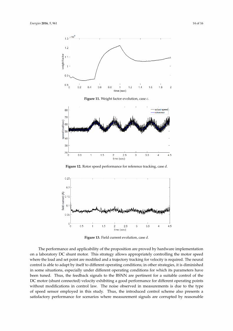
In case d, a trajectory tracking performance is presented. The first 0.8 s a steady state rotor speedis exhibited, after the reference speed is modified as a time function for trajectory tracking evaluation.The proposed adaptive controller achieves the reference speed requirements (Figure 12). This kindof performance is one of the main advantages of the adaptive controller when a design structure hasbeen conditioned.
It is evident that the proposed controller confirms its faster response; therefore, it could maintainsimilar behavior for diverse disturbances and different system requirements. In this study, this is theonly control variable; initially, the motor is operating at 52 rad/s with constant load torque. As a DCshunt motor, the field current is variable but the magnitude presented is less than the armaturecurrent (Figure 13). This feature allows complex load torque specifications for variable rotor speeds.The behavior is a consequence of speed reference demands.
Energies 2016, 9, 961 14 of 16
Figure 11. Weight factor evolution, case c.
Figure 12. Rotor speed performance for reference tracking, case d.
Figure 13. Field current evolution, case d.
The performance and applicability of the proposition are proved by hardware implementationon a laboratory DC shunt motor. This strategy allows appropriately controlling the motor speedwhere the load and set point are modified and a trajectory tracking for velocity is required. The neuralcontrol is able to adapt by itself to different operating conditions; in other strategies, it is diminishedin some situations, especially under different operating conditions for which its parameters havebeen tuned. Thus, the feedback signals to the BSNN are pertinent for a suitable control of theDC motor (shunt connected) velocity exhibiting a good performance for different operating pointswithout modifications in control law. The noise observed in measurements is due to the typeof speed sensor employed in this study. Thus, the introduced control scheme also presents asatisfactory performance for scenarios where measurement signals are corrupted by reasonable

Energies 2016, 9, 961 15 of 16
noise levels. Hence, the applicability of the proposed control approach has been demonstratedby real-life experimental results.
6. Conclusions
In this paper, a B-spline neural networks based adaptive control scheme for angular velocityreference trajectory tracking tasks for DC shunt motors was introduced. The presented controlleronly requires measurements of the velocity output signal. It was shown that with a prior off-lineneural network design, a robust and adaptive controller can be synthesized for this nonlineardynamic system. The instantaneous learning rule allows that the controller adapts by itself in eachdemanded operating condition. The same behavior is exhibited with real world operating conditions ofthe motor. For this proposition, it is unnecessary to use some mathematical model and the dependencyof the motor parameters is omitted. Moreover, measurements or real-time estimations of acceleration,current and disturbance signals are also avoided. The main feature is an adaptive nature and aneasy implementation in physical motors. Experimental laboratory tests on a controlled DC shuntmotor were included to show the effectiveness and efficiency of the proposed control design fordiverse velocity operating conditions and distinct load torque inputs. In addition, the introducedcontrol scheme also presents a satisfactory performance for scenarios where measurement signals arecorrupted by reasonable noise levels. Therefore, we can conclude that the output feedback trackingcontrol scheme represents a very good alternative choice for DC shunt electric motors.
Acknowledgments: This work has been supported by the CONACYT project under grant 266333 (sabbatical stay),and by Universidad Panamericana (Campus Guadalajara) under grant UP-CI-2015-FING-06.
Author Contributions: Ruben Tapia-Olvera, contributed obtaining the motor parameter, and with the design,training and implementation of the neural network controller. Francisco Beltran-Carbajal, contributed to thesynthesis and evaluation of the control scheme. Omar Aguilar-Mejia, analyzed the Control Design, assistedin control software assembling test, and analyzed the experimental data. Antonio Valderrabano-Gonzalez,contributed to article preparation, data analysis, and general management of the project.
Conflicts of Interest: The authors declare no conflict of interest.
References
1. Sun, J.; Chai, Y.; Su, C.; Zhu, Z.; Luo, X. BLDC motor speed control system fault diagnosis based on LRGFneural network and adaptive lifting scheme. Appl. Soft Comput. 2014, 14, 609–622.
2. Mekki, H.; Benzineb, O.; Boukhetala, D.; Tadjine, M.; Benbouzid, M. Sliding mode based fault detectionreconstruction and fault tolerant control scheme for motor systems. ISA Trans. 2015, 57, 340–351.
3. Li, C.-L.; Li, W.; Li, F.-D. Chaos induced in Brushless DC Motor via current time-delayed feedback. Optik2014, 125, 6589–6593.
4. Léchappé, V.; Salas, O.; de León, J.; Plestan, F.; Moulay, E.; Glumineau, A. Predictive control of disturbedsystems with input delay: Experimental validation on a DC motor. IFAC 2015, 48, 292–297.
5. Tepljakov, A.; Gonzalez, E.A.; Petlenkov, E.; Belikov, J.; Monje, C.A.; Petrás, I. Incorporation of fractional-orderdynamics into an existing PI/PID DC motor control loop. ISA Trans. 2016, 60, 262–273.
6. Kanojiya, R.G.; Meshram, P.M. Optimal tuning of PI controller for speed control of DC motor drive usingparticle swarm optimization. In Proceedings of the IEEE International Conference on Advances in PowerConversion and Energy Technologies (APCET), Mylavaram, India, 2–4 August 2012.
7. Jayaprakash, S. Comparison of solar based closed loop DC-DC converter using PID and Fuzzy Logic Controlfor Shunt motor drive. In Proceedings of the IEEE Conference on Emerging Trends In New & RenewableEnergy Sources and Energy Management, Chennai, India, 16–17 December 2014.
8. Wang, J.-J. A common sharing method for current and flux-linkage controlof switched reluctance motor.Electr. Power Syst. Res. 2016, 131, 19–30.
9. Alyaqout, S.F.; Papalambros, P.Y.; Ulsoy, A.G. Combined robust design and robust control of an electricDC motor. IEEE/ASME Trans. Mechatron. 2011, 16, 574–582.
10. Bai, R. Neural network control-based adaptive design for a class of DC motor Systems with the fullstate constraints. Neurocomputing 2015, 168, 65–69.

Energies 2016, 9, 961 16 of 16
11. Zaki, A.M.; El-Bardini, M.; Soliman, F.A.S.; Sharaf, M.M. Embedded two level direct adaptive fuzzy controllerfor DC motor speed control. Ain Shams Eng. J. 2015, in press.
12. Krause, P.C.; Wasynczuk, O.; Sudhoff, S.D. Analysis of Electric Machinery and Drive Systems, 2nd ed.;Wiley-IEEE Press: Hoboken, NJ, USA, 2002.
13. Topalov, A.V.; Cascella, G.L.; Giordano, V.; Cupertino, F.; Kaynak, O. Sliding mode neuro-adaptive control ofelectric drives. IEEE Trans. Ind. Electron. 2007, 54, 671–679.
14. Naso, D.; Cupertino, F.; Turchiano, B. Precise position control of tubular linear motors with neural networksand composite learning. Control Eng. Pract. 2010, 18, 515–522.
15. Tapia-Olvera, R.; Aguilar-Mejía, O.; Minor-Popocatl, H.; Santiago-Tepantlan, C. Power system stabilizer andsecondary voltage regulator tuning for multimachine power systems. Electr. Power Compon. Syst. 2012, 40,1751–1767.
16. Aguilar-Mejía, O.; Tapia-Olvera, R.; Valderrabano-Gonzalez, A.; Cambero, I.R. Adaptive neural networkcontrol of chaos in permanent magnet synchronous motor. Intell. Autom. Soft Comput. 2015, 22, 499–507.
17. Aguilar, O.; Tapia, R.; Valderrabano, A.; Minor, H. Design and performance comparison of PI and adaptivecurrent controllers for a WECS. IEEE Lat. Am. Trans. 2015, 13, 1361–1368.
18. Brown, M.; Harris, C. Neurofuzzy Adaptive Modelling and Control; Prentice Hall International: Upper SaddleRiver, NJ, USA, 1994.
19. Aguilera, A.M.; Aguilera-Morillo, M.C. Comparative study of different B-spline approaches for functional data.Math. Comput. Model. 2013, 58, 1568–1579.
20. Deng, H.; Srinivasan, D.; Oruganti, R. A B-spline network based neural controller for power electronic applications.Neurocomputing 2010, 73, 593–601.
21. Utkin, V.; Guldner, J.; Shi, J. Sliding Mode Control in Electro-Mechanical Systems, 2nd ed.; CRC Press: Boca Raton,FL, USA, 2009.
22. Damiano, A.; Gatto, G.L.; Marongiu, I.; Pisano, A. Second-order sliding-mode control of DC drives. IEEE Trans.Ind. Electron. 2004, 51, 364–373.
c© 2016 by the authors; licensee MDPI, Basel, Switzerland. This article is an open accessarticle distributed under the terms and conditions of the Creative Commons Attribution(CC-BY) license (http://creativecommons.org/licenses/by/4.0/).
Powered by TCPDF (www.tcpdf.org)