Embed Size (px)
Citation preview
Eurographics/ ACM SIGGRAPH Symposium on Computer Animation (2014)Vladlen Koltun and Eftychios Sifakis (Editors)
An Adaptive Virtual Node Algorithm with Robust MeshCutting
Yuting Wang† Chenfanfu Jiang‡ Craig Schroeder† Joseph Teran†
†Department of Mathematics ‡Department of Computer ScienceUniversity of California, Los Angeles
AbstractWe present a novel virtual node algorithm (VNA) for changing tetrahedron mesh topology to represent arbitrarycutting triangulated surfaces. Our approach addresses a number of shortcomings in the original VNA of [MBF04].First, we generalize the VNA so that cuts can pass through tetrahedron mesh vertices and lie on mesh edges andfaces. The original algorithm did not make sense for these cases and required often ambiguous perturbation of thecutting surface to avoid them. Second, we develop an adaptive approach to the definition of embedded materialused for element duplication. The original algorithm could only handle a limited number of configurations whichrestricted cut surfaces to have curvature at the scale of the tetrahedron elements. Our adaptive approach allowsfor cut surfaces with curvatures independent of the embedding tetrahedron mesh resolution. Finally, we present anovel, provably-robust floating point mesh intersection routine that accurately registers triangulated surface cutsagainst the background tetrahedron mesh without the need for exact arithmetic.
Categories and Subject Descriptors (according to ACM CCS): I.3.5 [Computer Graphics]: Computational Geometryand Object Modeling—Physically based modeling;
1. Introduction
The virtual node algorithm was developed to model topolog-ical changes defined by cuts in a tetrahedron mesh that donot lie on mesh facet boundaries [MBF04]. Although simplysplitting a tetrahedron mesh along element faces is the sim-plest means of changing mesh topology, it limits the paths ofcutting surfaces to be aligned with the facets of the originalgrid. The VNA was designed to generalize this approach tocuts that follow more arbitrary geometric paths. Avoidanceof expensive tetrahedral re-meshing approaches that rebuildthe mesh to respect propagating cuts was the primary moti-vation. With the VNA, topological changes are achieved byduplicating mesh elements that intersect the cut. Duplicatecopies of mesh elements then contain only a portion of thematerial being modeled (often referred to as embedded ma-terial), but all duplicate mesh elements are copies of originalelements and thus have predictable (and ideally high quality)conditioning.
† e-mail: {yuting,craig,teran}@math.ucla.edu‡ e-mail: [email protected]
However, as pointed out in [SDF07] the original algorithmdoes have some obvious limitations. First, it is often desir-able to allow a cut to pass through a mesh facet, but the orig-inal VNA approach requires all cuts to pass through tetra-hedron faces without intersecting the vertices of the mesh.Thus, cuts cannot lie on tetrahedron faces or pass throughvertices and must be perturbed to satisfy this constraint. Fur-thermore, a cut cannot cross a tetrahedron face more thanonce, thus the resolution of the tetrahedral mesh limits thetypes of allowable cuts, which is counter to the original mo-tivation of the algorithm. We provide a new approach thatremoves both of these limitations. First, we redevelop theoriginal VNA in a manner that allows cuts to pass through allmesh facets including vertices, edges and faces. Second, wedevelop an adaptive approach to the embedding and dupli-cation processes that allows cuts to pass through mesh facesan arbitrary number of times. This prevents limitations onthe cutting surface geometry imposed by the original VNAfrom the requirement that a cut only cross a tetrahedron facein one location. This adaptivity is only used to allow subse-quent cuts to a simulation mesh; we do not adaptively refinethe elements of the simulation mesh.
c© The Eurographics Association 2014.
Yuting Wang, Chenfanfu Jiang, Craig Schroeder & Joseph Teran / An Adaptive Virtual Node Algorithm with Robust Mesh Cutting
Figure 1: The maximally split configuration in 2D contains three types of cutting flags (top row). The red flag is set if inter-sections are registered at the green location and one of the blue locations on the triangle. In the maximally split configurationin 3D (top right), each color represents a different type of cutting face, which are shown individually on the bottom row. Thecorrespondence is, from bottom left to bottom right: green, red, yellow, and blue. For each of the four 3D cases (bottom), theshaded flag is set if intersections are registered at the red location, one of the green locations, and one of the blue locations onthe tetrahedron.
Lastly, we provide a novel mesh intersection algorithm forrobustly defining the intersections of a cutting triangulatedsurface against a tetrahedron mesh. This surface must be re-solved against the geometric primitives used for the duplica-tion process in the VNA, and it can be sensitive to roundingerrors. We provide a novel technique for robustly computingthe quantities in this process that are sensitive to roundingerrors.
2. Related work
Simulation of topological change in Lagrangian meshes wasintroduced to computer graphics in the pioneering work of[TF88]. [BSM∗02] and [WWD14] provide detailed surveysof applications of such mesh cutting. Early approaches typ-ically made use of simple separation along mesh elementboundaries [NTB∗91,MMA99,SWB01,MMDJ01,NvdS00]or even element deletion [FG99, CDA00, JBB∗10, FDA02].The available geometric detail in this type of approach wasincreased somewhat by subdivision of elements in the meshprior to splitting [MK00, BG00]; however, this tended to in-troduce elements with poor aspect ratios. More geometri-cally rich cutting surfaces were generated by allowing sep-aration along more arbitrary paths (albeit with the expenseof re-meshing) [NF99, OH99, OBH02]. Recently, such ap-proaches have been used to create some very compelling re-sults for a variety of materials [NKJF09, KMOD09, SSF09,
WRK∗10, CWSO13, WT08, WTGT09, GBO04, BWHT07].Embedded methods have been developed to minimize thecomplexity of re-meshing by embedding material surfacesinto the existing mesh [MG04, MBF04, BHTF07, SDF07,GBT07, PO09, HJST13]. Although these works generalizedthe approach to fracture, the embedding idea goes back atleast to free form deformations [SP86, FVDPT97, CGC∗02,TSB∗05]. Also, particle-based methods can provide flexibil-ity for topology change [PKA∗05]. Other interesting mod-els for cut patterns were developed in [MCK13, IO06, IO09,NF99].
3. Modified virtual node algorithm
The original VNA allows for a finite number of embeddedcuts in a given element. Specifically, individual tetrahedra inthe mesh can only be split into at most four embedded subre-gions (one associated with each node). This implies a “max-imally split” configuration of the mesh in which all possiblecuts have been made. In the original algorithm, each dis-joint piece in this configuration consists of the elements inthe one-ring of the nodes in the original mesh. Every othernode in the piece is then a duplicated copy of the originalnode. Although not originally described this way, the algo-rithm can be conceived of via manipulations in the materialconnections of these pieces in the maximally split configura-
c© The Eurographics Association 2014.
Yuting Wang, Chenfanfu Jiang, Craig Schroeder & Joseph Teran / An Adaptive Virtual Node Algorithm with Robust Mesh Cutting
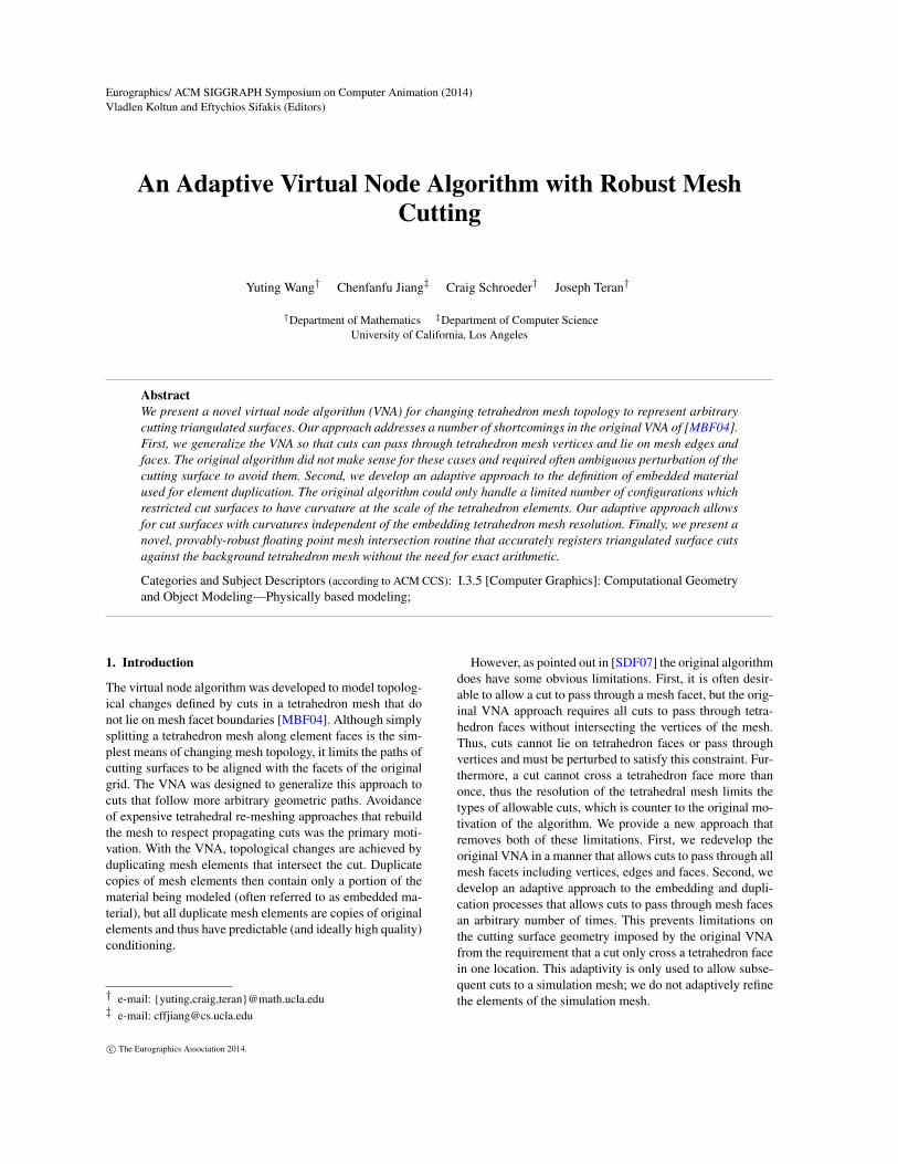
Original Mesh Cutting surface Set cutting flags Find connected components
Duplicate elementsMerge elementsSubdivide material meshSimulation mesh evolves
Second cut Cutting flags Duplicate and merge Final subdivided result
Algorithm
Overview
Figure 2: Schematic overview of our cutting algorithm.
tion as in [SDF07]. We will provide this material connectiondescription of our modified algorithm here.
First, we modify the available splits of a tetrahedron fromthe original four node-associated regions to 24 tetrahedra asshown in the top right of Figure 1. This modification of themaximally split configuration is designed to allow cuts topass through nodes of the embedding mesh, thus removing amajor limitation of the original VNA. We refer to the trian-gle boundaries separating each of the tetrahedron subregionsas cut faces since they will ultimately represent the embed-ded cut surface geometry. With this view, the first step inthe algorithm is to define which cut faces are active. An ac-tive cut face means that material is separated along it. Activecut faces for a tetrahedron are identified by considering theway each element of the cutting surface intersects the tetra-hedron. There are three cases in 2D and four in 3D, which aresummarized in Figure 1. We record this information usingcutting flags, which amounts to storing one bit for each pos-sible cut face (12 bits in 2D, 60 bits in 3D) that could be ac-tive. Then, we compute connected components of material inthe element, where sub-tetrahedra belong to the same com-ponent if the flag corresponding to the face between them isnot set. Note that unlike in [SDF07], this process has onlya finite number of possible cases and is straightforward toimplement. Afterwards, a copy of the embedding element ismade for each connected component. Each copy has all fourof its own nodes distinct from any of the other copies.
Next, tetrahedron copies of an original element created inthe first phase are compared to copies of the face-adjacentneighbors of the original element. If any of these copies
share a material connection through their neighboring face,the six nodes on the copies of the face are condensed to three,thus sewing the elements back together along the face. Ma-terial connection can be established efficiently by virtue ofthe small number of possible material configurations.
The original VNA did not allow for cut faces on theboundary of the embedding element. However, we show thatsimply including the faces of the 24 sub tetrahedra that layon the boundary of the embedding element as cut faces al-lows the algorithm to let cuts pass through embedding nodesand along embedding faces. This inability in the original al-gorithm required error-prone perturbation of cut surfaces toprevent these cases. Since we can handle degenerate cuts, wedo not require perturbation to avoid them. In fact, we showin Section 5 that the ability to register degeneracies allowsintersections to be computed robustly.
4. Adaptive cutting
The maximally split configuration in VNA approach placeslimitations on the possible geometries of the cutting sur-faces. This causes the curvature of the cut surface to be atmost at the scale of the tetrahedron resolution in the embed-ding mesh. This limitation was a large motivation for thework in [SDF07]. However, the generality of the availablecutting surfaces in [SDF07] comes at the cost of significantalgorithmic complexity. We show that an adaptive approachcan be used to add more flexibility in cut surface geometry.
To clarify the steps in the process, we will refer to theoriginal tetrahedron mesh as the simulation mesh. We will
c© The Eurographics Association 2014.
Yuting Wang, Chenfanfu Jiang, Craig Schroeder & Joseph Teran / An Adaptive Virtual Node Algorithm with Robust Mesh Cutting
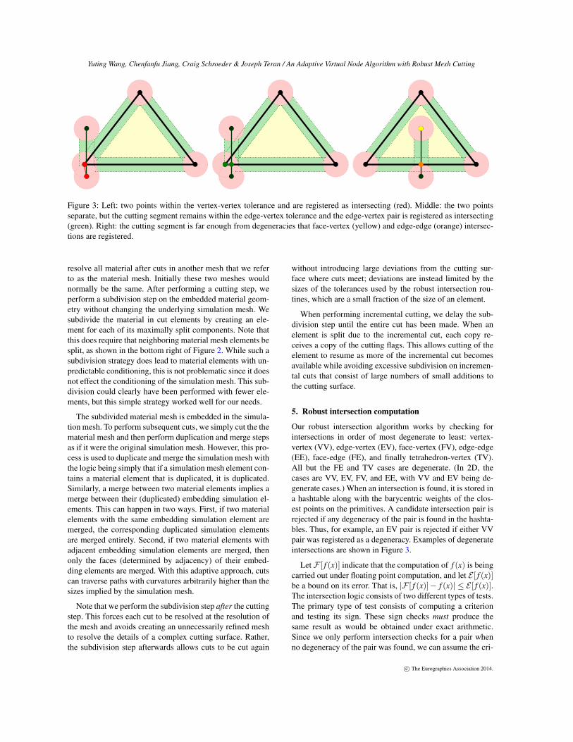
Figure 3: Left: two points within the vertex-vertex tolerance and are registered as intersecting (red). Middle: the two pointsseparate, but the cutting segment remains within the edge-vertex tolerance and the edge-vertex pair is registered as intersecting(green). Right: the cutting segment is far enough from degeneracies that face-vertex (yellow) and edge-edge (orange) intersec-tions are registered.
resolve all material after cuts in another mesh that we referto as the material mesh. Initially these two meshes wouldnormally be the same. After performing a cutting step, weperform a subdivision step on the embedded material geom-etry without changing the underlying simulation mesh. Wesubdivide the material in cut elements by creating an ele-ment for each of its maximally split components. Note thatthis does require that neighboring material mesh elements besplit, as shown in the bottom right of Figure 2. While such asubdivision strategy does lead to material elements with un-predictable conditioning, this is not problematic since it doesnot effect the conditioning of the simulation mesh. This sub-division could clearly have been performed with fewer ele-ments, but this simple strategy worked well for our needs.
The subdivided material mesh is embedded in the simula-tion mesh. To perform subsequent cuts, we simply cut the thematerial mesh and then perform duplication and merge stepsas if it were the original simulation mesh. However, this pro-cess is used to duplicate and merge the simulation mesh withthe logic being simply that if a simulation mesh element con-tains a material element that is duplicated, it is duplicated.Similarly, a merge between two material elements implies amerge between their (duplicated) embedding simulation el-ements. This can happen in two ways. First, if two materialelements with the same embedding simulation element aremerged, the corresponding duplicated simulation elementsare merged entirely. Second, if two material elements withadjacent embedding simulation elements are merged, thenonly the faces (determined by adjacency) of their embed-ding elements are merged. With this adaptive approach, cutscan traverse paths with curvatures arbitrarily higher than thesizes implied by the simulation mesh.
Note that we perform the subdivision step after the cuttingstep. This forces each cut to be resolved at the resolution ofthe mesh and avoids creating an unnecessarily refined meshto resolve the details of a complex cutting surface. Rather,the subdivision step afterwards allows cuts to be cut again
without introducing large deviations from the cutting sur-face where cuts meet; deviations are instead limited by thesizes of the tolerances used by the robust intersection rou-tines, which are a small fraction of the size of an element.
When performing incremental cutting, we delay the sub-division step until the entire cut has been made. When anelement is split due to the incremental cut, each copy re-ceives a copy of the cutting flags. This allows cutting of theelement to resume as more of the incremental cut becomesavailable while avoiding excessive subdivision on incremen-tal cuts that consist of large numbers of small additions tothe cutting surface.
5. Robust intersection computation
Our robust intersection algorithm works by checking forintersections in order of most degenerate to least: vertex-vertex (VV), edge-vertex (EV), face-vertex (FV), edge-edge(EE), face-edge (FE), and finally tetrahedron-vertex (TV).All but the FE and TV cases are degenerate. (In 2D, thecases are VV, EV, FV, and EE, with VV and EV being de-generate cases.) When an intersection is found, it is stored ina hashtable along with the barycentric weights of the clos-est points on the primitives. A candidate intersection pair isrejected if any degeneracy of the pair is found in the hashta-bles. Thus, for example, an EV pair is rejected if either VVpair was registered as a degeneracy. Examples of degenerateintersections are shown in Figure 3.
Let F [ f (x)] indicate that the computation of f (x) is beingcarried out under floating point computation, and let E [ f (x)]be a bound on its error. That is, |F [ f (x)]− f (x)| ≤ E [ f (x)].The intersection logic consists of two different types of tests.The primary type of test consists of computing a criterionand testing its sign. These sign checks must produce thesame result as would be obtained under exact arithmetic.Since we only perform intersection checks for a pair whenno degeneracy of the pair was found, we can assume the cri-
c© The Eurographics Association 2014.
Yuting Wang, Chenfanfu Jiang, Craig Schroeder & Joseph Teran / An Adaptive Virtual Node Algorithm with Robust Mesh Cutting
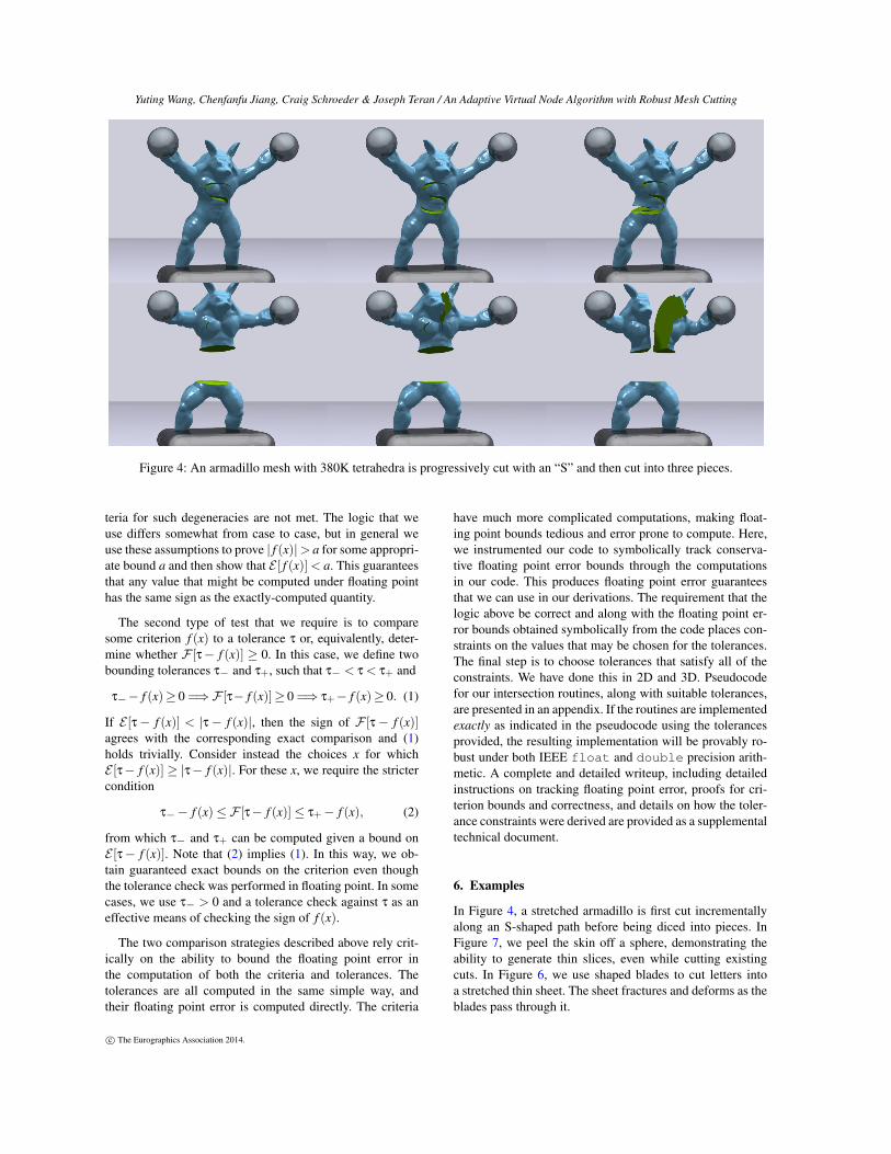
Figure 4: An armadillo mesh with 380K tetrahedra is progressively cut with an “S” and then cut into three pieces.
teria for such degeneracies are not met. The logic that weuse differs somewhat from case to case, but in general weuse these assumptions to prove | f (x)|> a for some appropri-ate bound a and then show that E [ f (x)]< a. This guaranteesthat any value that might be computed under floating pointhas the same sign as the exactly-computed quantity.
The second type of test that we require is to comparesome criterion f (x) to a tolerance τ or, equivalently, deter-mine whether F [τ− f (x)] ≥ 0. In this case, we define twobounding tolerances τ− and τ+, such that τ− < τ < τ+ and
τ−− f (x)≥ 0 =⇒F [τ− f (x)]≥ 0 =⇒ τ+− f (x)≥ 0. (1)
If E [τ− f (x)] < |τ− f (x)|, then the sign of F [τ− f (x)]agrees with the corresponding exact comparison and (1)holds trivially. Consider instead the choices x for whichE [τ− f (x)] ≥ |τ− f (x)|. For these x, we require the strictercondition
τ−− f (x)≤F [τ− f (x)]≤ τ+− f (x), (2)
from which τ− and τ+ can be computed given a bound onE [τ− f (x)]. Note that (2) implies (1). In this way, we ob-tain guaranteed exact bounds on the criterion even thoughthe tolerance check was performed in floating point. In somecases, we use τ− > 0 and a tolerance check against τ as aneffective means of checking the sign of f (x).
The two comparison strategies described above rely crit-ically on the ability to bound the floating point error inthe computation of both the criteria and tolerances. Thetolerances are all computed in the same simple way, andtheir floating point error is computed directly. The criteria
have much more complicated computations, making float-ing point bounds tedious and error prone to compute. Here,we instrumented our code to symbolically track conserva-tive floating point error bounds through the computationsin our code. This produces floating point error guaranteesthat we can use in our derivations. The requirement that thelogic above be correct and along with the floating point er-ror bounds obtained symbolically from the code places con-straints on the values that may be chosen for the tolerances.The final step is to choose tolerances that satisfy all of theconstraints. We have done this in 2D and 3D. Pseudocodefor our intersection routines, along with suitable tolerances,are presented in an appendix. If the routines are implementedexactly as indicated in the pseudocode using the tolerancesprovided, the resulting implementation will be provably ro-bust under both IEEE float and double precision arith-metic. A complete and detailed writeup, including detailedinstructions on tracking floating point error, proofs for cri-terion bounds and correctness, and details on how the toler-ance constraints were derived are provided as a supplementaltechnical document.
6. Examples
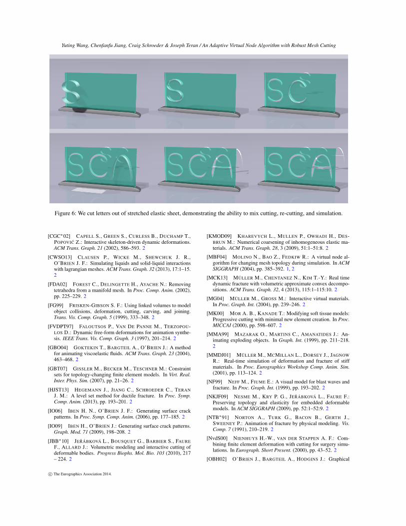
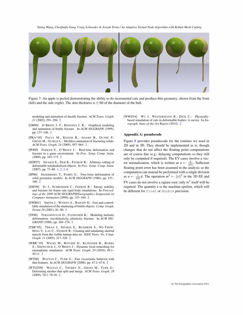
In Figure 4, a stretched armadillo is first cut incrementallyalong an S-shaped path before being diced into pieces. InFigure 7, we peel the skin off a sphere, demonstrating theability to generate thin slices, even while cutting existingcuts. In Figure 6, we use shaped blades to cut letters intoa stretched thin sheet. The sheet fractures and deforms as theblades pass through it.
c© The Eurographics Association 2014.
Yuting Wang, Chenfanfu Jiang, Craig Schroeder & Joseph Teran / An Adaptive Virtual Node Algorithm with Robust Mesh Cutting
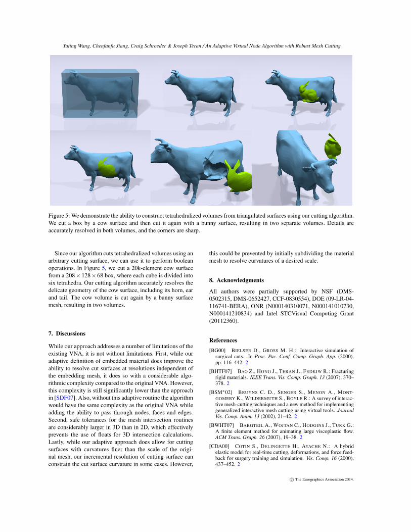
Figure 5: We demonstrate the ability to construct tetrahedralized volumes from triangulated surfaces using our cutting algorithm.We cut a box by a cow surface and then cut it again with a bunny surface, resulting in two separate volumes. Details areaccurately resolved in both volumes, and the corners are sharp.
Since our algorithm cuts tetrahedralized volumes using anarbitrary cutting surface, we can use it to perform booleanoperations. In Figure 5, we cut a 20k-element cow surfacefrom a 208×128×68 box, where each cube is divided intosix tetrahedra. Our cutting algorithm accurately resolves thedelicate geometry of the cow surface, including its horn, earand tail. The cow volume is cut again by a bunny surfacemesh, resulting in two volumes.
7. Discussions
While our approach addresses a number of limitations of theexisting VNA, it is not without limitations. First, while ouradaptive definition of embedded material does improve theability to resolve cut surfaces at resolutions independent ofthe embedding mesh, it does so with a considerable algo-rithmic complexity compared to the original VNA. However,this complexity is still significantly lower than the approachin [SDF07]. Also, without this adaptive routine the algorithmwould have the same complexity as the original VNA whileadding the ability to pass through nodes, faces and edges.Second, safe tolerances for the mesh intersection routinesare considerably larger in 3D than in 2D, which effectivelyprevents the use of floats for 3D intersection calculations.Lastly, while our adaptive approach does allow for cuttingsurfaces with curvatures finer than the scale of the origi-nal mesh, our incremental resolution of cutting surface canconstrain the cut surface curvature in some cases. However,
this could be prevented by initially subdividing the materialmesh to resolve curvatures of a desired scale.
8. Acknowledgments
All authors were partially supported by NSF (DMS-0502315, DMS-0652427, CCF-0830554), DOE (09-LR-04-116741-BERA), ONR (N000140310071, N000141010730,N000141210834) and Intel STCVisual Computing Grant(20112360).
References
[BG00] BIELSER D., GROSS M. H.: Interactive simulation ofsurgical cuts. In Proc. Pac. Conf. Comp. Graph. App. (2000),pp. 116–442. 2
[BHTF07] BAO Z., HONG J., TERAN J., FEDKIW R.: Fracturingrigid materials. IEEE Trans. Vis. Comp. Graph. 13 (2007), 370–378. 2
[BSM∗02] BRUYNS C. D., SENGER S., MENON A., MONT-GOMERY K., WILDERMUTH S., BOYLE R.: A survey of interac-tive mesh-cutting techniques and a new method for implementinggeneralized interactive mesh cutting using virtual tools. JournalVis. Comp. Anim. 13 (2002), 21–42. 2
[BWHT07] BARGTEIL A., WOJTAN C., HODGINS J., TURK G.:A finite element method for animating large viscoplastic flow.ACM Trans. Graph. 26 (2007), 19–38. 2
[CDA00] COTIN S., DELINGETTE H., AYACHE N.: A hybridelastic model for real-time cutting, deformations, and force feed-back for surgery training and simulation. Vis. Comp. 16 (2000),437–452. 2
c© The Eurographics Association 2014.
Yuting Wang, Chenfanfu Jiang, Craig Schroeder & Joseph Teran / An Adaptive Virtual Node Algorithm with Robust Mesh Cutting
Figure 6: We cut letters out of stretched elastic sheet, demonstrating the ability to mix cutting, re-cutting, and simulation.
[CGC∗02] CAPELL S., GREEN S., CURLESS B., DUCHAMP T.,POPOVIC Z.: Interactive skeleton-driven dynamic deformations.ACM Trans. Graph. 21 (2002), 586–593. 2
[CWSO13] CLAUSEN P., WICKE M., SHEWCHUK J. R.,O’BRIEN J. F.: Simulating liquids and solid-liquid interactionswith lagrangian meshes. ACM Trans. Graph. 32 (2013), 17:1–15.2
[FDA02] FOREST C., DELINGETTE H., AYACHE N.: Removingtetrahedra from a manifold mesh. In Proc. Comp. Anim. (2002),pp. 225–229. 2
[FG99] FRISKEN-GIBSON S. F.: Using linked volumes to modelobject collisions, deformation, cutting, carving, and joining.Trans. Vis. Comp. Graph. 5 (1999), 333–348. 2
[FVDPT97] FALOUTSOS P., VAN DE PANNE M., TERZOPOU-LOS D.: Dynamic free-form deformations for animation synthe-sis. IEEE Trans. Vis. Comp. Graph. 3 (1997), 201–214. 2
[GBO04] GOKTEKIN T., BARGTEIL A., O’BRIEN J.: A methodfor animating viscoelastic fluids. ACM Trans. Graph. 23 (2004),463–468. 2
[GBT07] GISSLER M., BECKER M., TESCHNER M.: Constraintsets for topology-changing finite element models. In Virt. Real.Inter. Phys. Sim. (2007), pp. 21–26. 2
[HJST13] HEGEMANN J., JIANG C., SCHROEDER C., TERANJ. M.: A level set method for ductile fracture. In Proc. Symp.Comp. Anim. (2013), pp. 193–201. 2
[IO06] IBEN H. N., O’BRIEN J. F.: Generating surface crackpatterns. In Proc. Symp. Comp. Anim. (2006), pp. 177–185. 2
[IO09] IBEN H., O’BRIEN J.: Generating surface crack patterns.Graph. Mod. 71 (2009), 198–208. 2
[JBB∗10] JERÁBKOVÁ L., BOUSQUET G., BARBIER S., FAUREF., ALLARD J.: Volumetric modeling and interactive cutting ofdeformable bodies. Progress Biophs. Mol. Bio. 103 (2010), 217– 224. 2
[KMOD09] KHAREVYCH L., MULLEN P., OWHADI H., DES-BRUN M.: Numerical coarsening of inhomogeneous elastic ma-terials. ACM Trans. Graph. 28, 3 (2009), 51:1–51:8. 2
[MBF04] MOLINO N., BAO Z., FEDKIW R.: A virtual node al-gorithm for changing mesh topology during simulation. In ACMSIGGRAPH (2004), pp. 385–392. 1, 2
[MCK13] MÜLLER M., CHENTANEZ N., KIM T.-Y.: Real timedynamic fracture with volumetric approximate convex decompo-sitions. ACM Trans. Graph. 32, 4 (2013), 115:1–115:10. 2
[MG04] MÜLLER M., GROSS M.: Interactive virtual materials.In Proc. Graph. Int. (2004), pp. 239–246. 2
[MK00] MOR A. B., KANADE T.: Modifying soft tissue models:Progressive cutting with minimal new element creation. In Proc.MICCAI (2000), pp. 598–607. 2
[MMA99] MAZARAK O., MARTINS C., AMANATIDES J.: An-imating exploding objects. In Graph. Int. (1999), pp. 211–218.2
[MMDJ01] MÜLLER M., MCMILLAN L., DORSEY J., JAGNOWR.: Real-time simulation of deformation and fracture of stiffmaterials. In Proc. Eurographics Workshop Comp. Anim. Sim.(2001), pp. 113–124. 2
[NF99] NEFF M., FIUME E.: A visual model for blast waves andfracture. In Proc. Graph. Int. (1999), pp. 193–202. 2
[NKJF09] NESME M., KRY P. G., JERÁBKOVÁ L., FAURE F.:Preserving topology and elasticity for embedded deformablemodels. In ACM SIGGRAPH (2009), pp. 52:1–52:9. 2
[NTB∗91] NORTON A., TURK G., BACON B., GERTH J.,SWEENEY P.: Animation of fracture by physical modeling. Vis.Comp. 7 (1991), 210–219. 2
[NvdS00] NIENHUYS H.-W., VAN DER STAPPEN A. F.: Com-bining finite element deformation with cutting for surgery simu-lations. In Eurograph. Short Present. (2000), pp. 43–52. 2
[OBH02] O’BRIEN J., BARGTEIL A., HODGINS J.: Graphical
c© The Eurographics Association 2014.
Yuting Wang, Chenfanfu Jiang, Craig Schroeder & Joseph Teran / An Adaptive Virtual Node Algorithm with Robust Mesh Cutting
Figure 7: An apple is peeled demonstrating the ability to do incremental cuts and produce thin geometry, shown from the front(left) and the side (right). The skin thickness is 1/60 of the diameter of the ball.
modeling and animation of ductile fracture. ACM Trans. Graph.21 (2002), 291–294. 2
[OH99] O’BRIEN J. F., HODGINS J. K.: Graphical modelingand animation of brittle fracture. In ACM SIGGRAPH (1999),pp. 137–146. 2
[PKA∗05] PAULY M., KEISER R., ADAMS B., DUTRÉ P.,GROSS M., GUIBAS L.: Meshless animation of fracturing solids.ACM Trans. Graph. 24 (2005), 957–964. 2
[PO09] PARKER E., O’BRIEN J.: Real-time deformation andfracture in a game environment. In Proc. Symp. Comp. Anim.(2009), pp. 165–175. 2
[SDF07] SIFAKIS E., DER K., FEDKIW R.: Arbitrary cutting ofdeformable tetrahedralized objects. In Proc. Symp. Comp. Anim.(2007), pp. 73–80. 1, 2, 3, 6
[SP86] SEDERBERG T., PARRY S.: Free-form deformation ofsolid geometric models. In ACM SIGGRAPH (1986), pp. 151–160. 2
[SSF09] SU J., SCHROEDER C., FEDKIW R.: Energy stabilityand fracture for frame rate rigid body simulations. In Proceed-ings of the 2009 ACM SIGGRAPH/Eurographics Symposium onComputer Animation (2009), pp. 155–164. 2
[SWB01] SMITH J., WITKIN A., BARAFF D.: Fast and control-lable simulation of the shattering of brittle objects. Comp. Graph.Forum 20 (2001), 81–90. 2
[TF88] TERZOPOULOS D., FLEISCHER K.: Modeling inelasticdeformation: viscolelasticity, plasticity, fracture. In ACM SIG-GRAPH (1988), pp. 269–278. 2
[TSB∗05] TERAN J., SIFAKIS E., BLEMKER S., NG-THOW-HING V., LAU C., FEDKIW R.: Creating and simulating skeletalmuscle from the visible human data set. IEEE Trans. Vis. Comp.Graph. 11 (2005), 317–328. 2
[WRK∗10] WICKE M., RITCHIE D., KLINGNER B., BURKES., SHEWCHUK J., O’BRIEN J.: Dynamic local remeshing forelastoplastic simulation. ACM Trans. Graph. 29 (2010), 49:1–49:11. 2
[WT08] WOJTAN C., TURK G.: Fast viscoelastic behavior withthin features. In ACM SIGGRAPH (2008), pp. 47:1–47:8. 2
[WTGT09] WOJTAN C., THÜREY N., GROSS M., TURK G.:Deforming meshes that split and merge. ACM Trans. Graph. 28(2009), 76:1–76:10. 2
[WWD14] WU J., WESTERMANN R., DICK C.: Physically-based simulation of cuts in deformable bodies: A survey. In Eu-rograph. State-of-the-Art Report (2014). 2
Appendix A: pseudocode
Figure 8 provides pseudocode for the routines we used in2D and in 3D. They should be implemented as is, thoughchanges that do not affect the floating point computationsare of course fine (e.g., delaying computations so they willonly be computed if required). The EV cases involve a vec-tor normalization, which is written as u← u
‖u‖ . Sufficientfloating point error has been assumed in the analysis so thecomputation can instead be performed with a single divisionas u← 1
‖u‖ u. The operation m2 ← ‖r‖2 in the 3D EE and
FV cases do not involve a square root; only m2 itself will berequired. The quantity ε is the machine epsilon, which willbe different for float or double precision.
c© The Eurographics Association 2014.

Yuting Wang, Chenfanfu Jiang, Craig Schroeder & Joseph Teran / An Adaptive Virtual Node Algorithm with Robust Mesh Cutting
Algorithm 1 Intersection routines for 2Dfunction COMPUTE_TOLERANCES(A,B)
La←maximum bound box edge length of mesh ALb←maximum bound box edge length of mesh Bs←√
ε; L← 1+5ε
1−7s (La +Lb); t = sLσ = 6.5t; τ = 4.5t; σ = 5.5t; κ = 21εL2
end functionfunction VERTEX_VERTEX(A,B)
return ‖A−B‖2 ≤ σ2
end functionfunction EDGE_VERTEX(A,B,P)
u← A−B; m←‖u‖; u← um
w← P−A; a← u ·w; a← m− aif m≤ σ or |u×w|> τ or a < 0 or a < 0 then
return (FALSE,0)return (TRUE, a
m )end functionfunction EDGE_EDGE(A,B,P)
aA← (A−P)× (Q−P); aB← (B−P)× (Q−P)aP← (P−A)× (B−A); aQ← (Q−A)× (B−A)if |aP| ≤ κ or |aQ| ≤ κ or sgn(aP) = sgn(aQ) or|aA| ≤ κ or |aB| ≤ κ or sgn(aA) = sgn(aB) thenreturn (FALSE,0,0)
return (TRUE, aAaA−aB
, aPaP−aQ
)
end functionfunction TRIANGLE_VERTEX(A,B,P)
aA← (B−P)× (C−P); aB← (P−A)× (C−A)aC← (B−A)× (P−A)if |aA| ≤ κ or |aB| ≤ κ or |aC| ≤ κ or
sgn(aA) 6= sgn(aB) or sgn(aB) 6= sgn(aC) thenreturn (FALSE,0,0,0)
return (TRUE, aAaA+aB+aC
, aBaA+aB+aC
, aCaA+aB+aC
)end function
Algorithm 2 Intersection routines for 3D (part I)function COMPUTE_TOLERANCES(A,B)
La←maximum bound box edge length of mesh ALb←maximum bound box edge length of mesh Bs←√
ε; a←√
s; L← 1+5ε
1−7a (La +Lb)
b← sa; c = aL; d = L2; e = bLd; f = εd2
σ = 6.5c; τ = 4.5c; δ = 2.25c; γ = 2.25cσ = 5.5c; µ = 24e; ρ = 56e; ζ = 1317 fλ = 1215 f ; φ = 470 f ; ν = 6844.5 f ; ξ = 56e
end function
function VERTEX_VERTEX(A,B)return ‖A−B‖2 ≤ σ
2
end function
Algorithm 3 Intersection routines for 3D (part II)function EDGE_VERTEX(A,B,P)
u← A−B; m←‖u‖; u← um
w← P−A; a← u ·w; a← m− aif m≤ σ or ‖u×w‖2 > τ
2 or a < 0 or a < 0 thenreturn (FALSE,0)
return (TRUE, am )
end functionfunction EDGE_EDGE(A,B,P,Q)
u← B−A; v← Q−P; r← u×v; m2←‖r‖2
w← P−A; d← r ·w; n← r×w; a = n · vb = n ·u; a = m2− a; b = m2− bif m2 ≤ λ or d2 > γ
2m2 ora≤ φ or b≤ φ or a≤ φ or b≤ φ thenreturn (FALSE,0,0)
return (TRUE, am2 ,
bm2 )
end functionfunction TRIANGLE_VERTEX(A,B,C,P)
u← B−A; v←C−A; r← u× v; m2←‖r‖2
w← P−A; d← r ·w; n← r×w; b = n · vc =−n ·u; a = m2− b− cif m2 ≤ ν or d2 > δ
2m2 ora≤ ζ or b≤ ζ or c≤ ζ thenreturn (FALSE,0,0,0)
return (TRUE, am2 ,
bm2 ,
cm2 )
end functionfunction TRIANGLE_EDGE(A,B,C,P,Q)
a← A−Q; b← B−Q; c←C−Qp← P−Q; vP← ((A−P)× (B−P)) · (C−P)vA← (b× c) · p; vB← (c×a) · pvC← (a×b) · p; vQ← (a×b) · cif |vA| ≤ µ or |vB| ≤ µ or |vC| ≤ µ or
sgn(vA) 6= sgn(vB) or sgn(vB) 6= sgn(vC) or|vP| ≤ ξ or |vQ| ≤ ξ or sgn(vP) = sgn(vQ) thenreturn (FALSE,0,0,0,0)
return (TRUE, vAvA+vB+vC
, vBvA+vB+vC
, vCvA+vB+vC
, vPvP−vQ
)
end functionfunction TETRAHEDRON_VERTEX(A,B,C,D,P)
vA← ((B−P)× (C−P)) · (D−P)vB← ((P−A)× (C−A)) · (D−A)vC← ((B−A)× (P−A)) · (D−A)vD← ((B−A)× (C−A)) · (P−A)s← vA + vB + vC + vDif |vA| ≤ ρ or |vB| ≤ ρ or |vC| ≤ ρ or |vC| ≤ ρ or
sgn(vA) 6= sgn(vB) or sgn(vB) 6= sgn(vC) orsgn(vC) 6= sgn(vD) thenreturn (FALSE,0,0,0,0)
return (TRUE, vAs ,
vBs ,
vCs ,
vDs )
end function
Figure 8: Algorithms for robust intersection under floating point.
c© The Eurographics Association 2014.


![ROBUST ADAPTIVE BEAMFORMER WITH · PDF filebust adaptive beamforming, ... strained adaptive beamformer is studied in [5, 6] and widely used thereafter. Recently some interesting robust](https://img.pdfslide.net/doc/110x75/5ab383fc7f8b9ad9788e2684/robust-adaptive-beamformer-with-adaptive-beamforming-strained-adaptive.jpg)


![Workshop] Robust and Adaptive Part 1](https://img.pdfslide.net/doc/110x75/55129b434a7959c4028b4a18/workshop-robust-and-adaptive-part-1.jpg)