Embed Size (px)
Citation preview

Universitat Ulm, Fakultat fur Informatik,Abteilung Programmiermethodik und Compilerbau
An Agile Development Methodology for Knowledge-Based Systems
Including a Java Framework for Knowledge Modeling
and Appropriate Tool Support
Dissertation zur Erlangung des Doktorgrades Dr.rer.nat.der Fakultat fur Informatik der Universitat Ulm
UN
IVERSITÄT
ULM·
SC
IEN
DO
·DOCENDO·C
UR
AN
DO
·
Holger Knublauch
aus Berlin-Lichterfelde
Amtierender Dekan:
Prof. Dr. Gunther Palm
Gutachter:
Prof. Dr. Helmuth Partsch
Prof. Dr. Dr. Franz-Josef Radermacher
Datum der Promotionsprufung: 16.10.2002

Abstract
The goal of this thesis is to help make the development of knowledge-based systems moreefficient. For that purpose, it proposes a new, agile software and knowledge engineeringmethodology, called XP.K (eXtreme Programming of Knowledge-based systems). Thismethodology is based on the four values simplicity, community, feedback, and courage, andapplies object-oriented Round-Trip Engineering to knowledge modeling.
The thesis is founded on the observation that for most knowledge-based systems, knowl-edge must necessarily be modeled evolutionary, in a close collaboration between domainexperts and engineers. The author argues that existing “heavy-weight” development meth-odologies from object-oriented Software Engineering and Knowledge Engineering are ofteninefficient, because they make changes in knowledge models too expensive. Furthermore,they provide little support for the transitions between knowledge, knowledge models, andthe remaining executable system. The starting point of XP.K is the hypothesis that “light-weight” – or agile – development processes (such as Extreme Programming) are suitablefor knowledge modeling, because they are optimized for projects with frequently chang-ing requirements and models and rely on a minimum of modeling artifacts with smoothtransitions between them.
XP.K applies the main principles of Extreme Programming to knowledge modeling.The development process relies heavily on communication. Domain experts and knowledgeengineers collaborate in the definition of metamodels (ontologies) and knowledge is acquiredand tested in pairs. Ontologies are implemented in the object-oriented language which isalso used for the remaining modules of the system. These ontologies transparently exposetheir structure and semantics both at run-time and build-time. At run-time, reflectionis used to analyze the ontology, so that generic knowledge acquisition tools and inferenceengines can be (re-)used, reducing the cost of changing ontologies. At build-time, Round-Trip Engineering is used to extract and edit the structure of the ontology in UML, sothat all information and documentation can remain centrally in the code. Prototypes areproduced rapidly and frequently exposed to automated tests and constraint checks.
XP.K is supported by a comprehensive, ready-to-use framework for implementing know-ledge-based systems in Java. This includes an extension to the Java component modelJavaBeans for the representation of semantic constraints on object states and a genericframework for knowledge acquisition tools. Evidence for the efficiency of XP.K is providedby case studies from areas such as clinical decision-support and process modeling for multi-agent systems.
i


Prologue
The wind will not stop. Gusts of sand swirl before me, stinging myface. But there is still too much to see and marvel at, the worldvery much alive in the bright light and wind, exultant with thefever of spring, the delight of morning. Strolling on, it seems tome that the strangeness and wonder of existence are emphasizedhere, in the desert, by the comparative sparsity of the flora andfauna: life not crowded upon life as in other places but scatteredabroad in spareness and simplicity, with a generous gift of spacefor each herb and bush and tree, each steam of grass, as that theliving organism stands out bold and brave and vivid against thelifeless sand and barren rock. The extreme clarity of the desertlight is equaled by the extreme individuation of desert life forms.Love flowers best in openness and freedom.
Edward Abbey, Desert Solitaire (1968)
iii

Preface
This thesis is based on the results of two related research projects carried out at theDepartment of Business Processes and Telematics at the Research Institute for AppliedKnowledge Processing (FAW) at the University of Ulm, Germany. The project ANIS(1998–2000, funded by the German governmental department of Education and Research(BMBF)) aimed at developing a prototypical knowledge-based patient monitor for decisionsupport in anesthesia. The project AGIL (2000–2002, funded by the German ResearchFoundation (DFG)) focused on the development of a multi-agent system to optimize theclinical information flow. The author was principal researcher in both projects whichwere conducted in cooperation with clinical experts and researchers from the Institute forPsychology and Ergonomics at the Technical University of Berlin.
Acknowledgements
I am indebted to Dr. Thomas Rose, head of the Department of Business Processes andTelematics at the FAW, Ulm, and the project leader in AGIL and ANIS. Thomas hasmade valuable critical comments and other contributions to this research and my scientificwork. Furthermore, he has generated an inspiring working environment in which I couldunfold freely. An essential part of this environment was my long running roomate GerhardPeter, who taught me many important lessons on scientific research and contributed to afriendly and motivating workplace. Special thanks to Martin Sedlmayr, who has started asa student research assistant in the ANIS project and later became a leading creative mindat the FAW. Several discussions with Martin have lead to important advances in ANIS andhave laid the foundation of the KBeans approach. On this occasion, I would also like toexpress my gratitude to my (former) colleagues in the department, in particular to MartinFunffinger, Dr. Christian Greiner and Dr. Christian Rupprecht.
I would like to acknowledge Holger Koth, M.D., who was my partner in the AGILproject in Berlin, and who has contributed to our knowledge modeling approach and theresulting clinical multi-agent system. Many thanks also to the eager participants of theExtreme Programming course at the University Ulm in fall, 2001, in which I had theopportunity to evaluate parts of my Extreme Programming approach with a real-worldproject.
Last but not least, I would like to express my gratitude to my supervisors Prof. Dr.Helmuth Partsch and Prof. Dr. Dr. Franz-Josef Radermacher for supporting this thesisand the Extreme Programming courses despite the rather unconventional topic. Prof.
v

Dr. Partsch has also laid the foundation of my scientific career by introducing me to thebasics of compiler construction, requirements engineering and software technology, and bysupervising my masters thesis in which I learned to appreciate the benefits of systematicengineering approaches – in those cases when requirements are relatively stable...
vi

Contents
1. Introduction 11.1. Problem . . . . . . . . . . . . . . . . . . . . . . . . . . . . . . . . . . . . . 11.2. Existing Approaches and their Limitations . . . . . . . . . . . . . . . . . . 31.3. My Approach . . . . . . . . . . . . . . . . . . . . . . . . . . . . . . . . . . 41.4. Research Contributions . . . . . . . . . . . . . . . . . . . . . . . . . . . . . 61.5. Overview of this Thesis . . . . . . . . . . . . . . . . . . . . . . . . . . . . . 7
2. Requirements of Development Methodologies for Knowledge-Based Systems 92.1. Development Methodologies . . . . . . . . . . . . . . . . . . . . . . . . . . 92.2. From Knowledge to Knowledge-Based Systems (and back) . . . . . . . . . 11
2.2.1. Knowledge-Based Systems . . . . . . . . . . . . . . . . . . . . . . . 112.2.2. Roles and Artifacts in the Development Process . . . . . . . . . . . 122.2.3. Knowledge Modeling as a Collaborative Process . . . . . . . . . . . 142.2.4. Knowledge Modeling as an Evolutionary Process . . . . . . . . . . . 15
2.3. Requirements of Development Methodologies . . . . . . . . . . . . . . . . . 182.3.1. Requirements of the Modeling Process . . . . . . . . . . . . . . . . 182.3.2. Requirements of the Modeling Languages . . . . . . . . . . . . . . . 192.3.3. Requirements of the Modeling Tools . . . . . . . . . . . . . . . . . 20
2.4. Summary . . . . . . . . . . . . . . . . . . . . . . . . . . . . . . . . . . . . 21
3. Object-Oriented Software Engineering 233.1. Paradigms . . . . . . . . . . . . . . . . . . . . . . . . . . . . . . . . . . . . 23
3.1.1. The Four Principles of Object-Orientation . . . . . . . . . . . . . . 233.1.2. Objects, Components, Patterns, Architectures, Frameworks . . . . . 24
3.2. Processes . . . . . . . . . . . . . . . . . . . . . . . . . . . . . . . . . . . . 263.2.1. Systematic Engineering Processes . . . . . . . . . . . . . . . . . . . 263.2.2. Agile Processes . . . . . . . . . . . . . . . . . . . . . . . . . . . . . 31
3.3. Languages . . . . . . . . . . . . . . . . . . . . . . . . . . . . . . . . . . . . 363.3.1. The Unified Modeling Language (UML) . . . . . . . . . . . . . . . 363.3.2. Metamodels and the Meta Object Facility (MOF) . . . . . . . . . . 383.3.3. Object-Oriented Programming Languages . . . . . . . . . . . . . . 39
3.4. Tools . . . . . . . . . . . . . . . . . . . . . . . . . . . . . . . . . . . . . . . 393.4.1. Integrated Development Environments (IDEs) . . . . . . . . . . . . 39
vii

Contents
3.4.2. CASE Tools and Round-Trip Engineering . . . . . . . . . . . . . . 403.5. Summary . . . . . . . . . . . . . . . . . . . . . . . . . . . . . . . . . . . . 41
4. Knowledge Engineering 434.1. Paradigms . . . . . . . . . . . . . . . . . . . . . . . . . . . . . . . . . . . . 43
4.1.1. Ontologies . . . . . . . . . . . . . . . . . . . . . . . . . . . . . . . . 444.1.2. Problem-Solving Methods . . . . . . . . . . . . . . . . . . . . . . . 444.1.3. An Architecture for Knowledge-Based Systems . . . . . . . . . . . . 45
4.2. Process . . . . . . . . . . . . . . . . . . . . . . . . . . . . . . . . . . . . . . 464.2.1. Ontology Modeling Approaches . . . . . . . . . . . . . . . . . . . . 474.2.2. Knowledge Engineering Methodologies . . . . . . . . . . . . . . . . 48
4.3. Languages . . . . . . . . . . . . . . . . . . . . . . . . . . . . . . . . . . . . 504.3.1. Ontology Specification with OKBC . . . . . . . . . . . . . . . . . . 514.3.2. Languages for Problem-Solving Methods (UPML) . . . . . . . . . . 54
4.4. Tools . . . . . . . . . . . . . . . . . . . . . . . . . . . . . . . . . . . . . . . 554.4.1. Protege-2000 . . . . . . . . . . . . . . . . . . . . . . . . . . . . . . 554.4.2. Other Tools . . . . . . . . . . . . . . . . . . . . . . . . . . . . . . . 58
4.5. Summary . . . . . . . . . . . . . . . . . . . . . . . . . . . . . . . . . . . . 58
5. Overview of the XP.K Methodology 615.1. Paradigms . . . . . . . . . . . . . . . . . . . . . . . . . . . . . . . . . . . . 63
5.1.1. Differences between Object-Orientation and Ontologies . . . . . . . 645.1.2. Semantic Transparency for Object Models . . . . . . . . . . . . . . 66
5.2. Process . . . . . . . . . . . . . . . . . . . . . . . . . . . . . . . . . . . . . . 685.2.1. The Values of XP.K . . . . . . . . . . . . . . . . . . . . . . . . . . . 685.2.2. The Principles of XP.K . . . . . . . . . . . . . . . . . . . . . . . . . 715.2.3. The Practices of XP.K . . . . . . . . . . . . . . . . . . . . . . . . . 725.2.4. Putting it all Together . . . . . . . . . . . . . . . . . . . . . . . . . 77
5.3. Languages . . . . . . . . . . . . . . . . . . . . . . . . . . . . . . . . . . . . 795.4. Tools . . . . . . . . . . . . . . . . . . . . . . . . . . . . . . . . . . . . . . . 82
5.4.1. Ontology (Class) Editors . . . . . . . . . . . . . . . . . . . . . . . . 825.4.2. Knowledge Base (Instance) Editors . . . . . . . . . . . . . . . . . . 83
5.5. Summary . . . . . . . . . . . . . . . . . . . . . . . . . . . . . . . . . . . . 84
6. KBeans: Implementing XP.K in Java 876.1. Reflection and JavaBeans . . . . . . . . . . . . . . . . . . . . . . . . . . . 886.2. KBeans: Adding Facets to JavaBeans . . . . . . . . . . . . . . . . . . . . . 89
6.2.1. Dynamic Facet Declarations . . . . . . . . . . . . . . . . . . . . . . 916.2.2. Static Facet Declarations . . . . . . . . . . . . . . . . . . . . . . . . 926.2.3. Coding Conventions . . . . . . . . . . . . . . . . . . . . . . . . . . 936.2.4. Accessing and Processing Facets . . . . . . . . . . . . . . . . . . . . 94
6.3. A Catalog of KBeans Facets . . . . . . . . . . . . . . . . . . . . . . . . . . 956.4. Application Scenarios . . . . . . . . . . . . . . . . . . . . . . . . . . . . . . 96
viii

Contents
6.4.1. Implementation of Semantically Rich Domain Models . . . . . . . . 976.4.2. Ontology Implementation . . . . . . . . . . . . . . . . . . . . . . . 986.4.3. Ontology Sharing and Mapping . . . . . . . . . . . . . . . . . . . . 996.4.4. Constraint Checking . . . . . . . . . . . . . . . . . . . . . . . . . . 1006.4.5. Semantic Annotation of Reusable Components . . . . . . . . . . . . 101
6.5. Discussion . . . . . . . . . . . . . . . . . . . . . . . . . . . . . . . . . . . . 1026.5.1. Related Work . . . . . . . . . . . . . . . . . . . . . . . . . . . . . . 1026.5.2. Benefits and Limitations of KBeans . . . . . . . . . . . . . . . . . . 104
6.6. Summary . . . . . . . . . . . . . . . . . . . . . . . . . . . . . . . . . . . . 105
7. KBeansShell: A Generic Framework for Knowledge Modeling Tools 1077.1. Architecture . . . . . . . . . . . . . . . . . . . . . . . . . . . . . . . . . . . 1087.2. Standard Modules . . . . . . . . . . . . . . . . . . . . . . . . . . . . . . . . 112
7.2.1. Persistence Modules . . . . . . . . . . . . . . . . . . . . . . . . . . 1127.2.2. View Modules . . . . . . . . . . . . . . . . . . . . . . . . . . . . . . 113
7.3. Using KBeansShell . . . . . . . . . . . . . . . . . . . . . . . . . . . . . . . 1207.4. The MetaKBeansShell . . . . . . . . . . . . . . . . . . . . . . . . . . . . . 1217.5. Summary . . . . . . . . . . . . . . . . . . . . . . . . . . . . . . . . . . . . 123
8. Case Studies 1258.1. The Clinical Decision Support System ANIS . . . . . . . . . . . . . . . . . 125
8.1.1. Domain Knowledge Acquisition in ANIS . . . . . . . . . . . . . . . 1268.1.2. Problem-Solving Methods in ANIS . . . . . . . . . . . . . . . . . . 1288.1.3. The Knowledge Acquisition Bottleneck . . . . . . . . . . . . . . . . 1288.1.4. A Rule Engine as a Byproduct of ANIS . . . . . . . . . . . . . . . . 129
8.2. The Clinical Multi-Agent System AGIL . . . . . . . . . . . . . . . . . . . . 1308.2.1. Process Knowledge Acquisition in AGIL . . . . . . . . . . . . . . . 1328.2.2. Agent Implementation and Test . . . . . . . . . . . . . . . . . . . . 1358.2.3. Discussion of XP.K for Agent Development . . . . . . . . . . . . . . 139
8.3. Summary . . . . . . . . . . . . . . . . . . . . . . . . . . . . . . . . . . . . 141
9. Discussion and Conclusion 1439.1. Discussion . . . . . . . . . . . . . . . . . . . . . . . . . . . . . . . . . . . . 1439.2. The Application Domain of XP.K . . . . . . . . . . . . . . . . . . . . . . . 1509.3. Open Issues and Potential Future Work . . . . . . . . . . . . . . . . . . . . 1529.4. Conclusion . . . . . . . . . . . . . . . . . . . . . . . . . . . . . . . . . . . . 153
Bibliography 155
Appendix 170
A. The Standard Facet Types of KBeans 171
ix

Contents
B. A Sample KBeans Ontology Class 183
C. A Sample KBeans Constraint Class 191
D. The Facets of XML Schema 193
E. The BeanModel Java interface 195
F. Class Diagram of the Meta Object Facility (MOF) 197
G. Java Libraries for Knowledge-Based Systems and Artificial Intelligence 199
H. The KBeans Logic package 201
x
1. Introduction
My goal is to help make the development of knowledge-based systems more efficient. Forthat purpose, I will present a new software and knowledge engineering methodology, calledXP.K (eXtreme Programming of Knowledge-based systems).
In this introductory chapter I will provide a brief overview of this document. First I willclarify the problem domain by describing the requirements of a typical knowledge-basedsystem (section 1.1). Then I will argue that existing development methodologies for suchsystems are often inefficient, because they fail to produce systems which are easy to change(section 1.2). The XP.K methodology reduces the cost of change by using an evolutionaryagile process based on eXtreme Programming (XP) [8]. I will outline XP.K in section 1.3.Finally, I will list my main contributions to research (section 1.4) and provide an overviewof the structure of the remaining document (section 1.5).
1.1. Problem
In order to introduce the problem and application domain of this document, I will startwith a simple example scenario. This scenario is based on various research and developmentprojects that I have been involved in, especially the projects ANIS [108, 76] and AGIL [105,167, 102]. Later chapters will refer to parts of this scenario.
Let’s assume our task is to develop a computer system that supports decision-makingin a local hospital. As indicated in figure 1.1, this hospital has various departments, suchas the reception, the ward, the operating room, and the laboratory. These departmentsshare a hospital-wide computer network with a central patient database. This databaseis permanently updated with various types of patient data, such as administrative data,blood sample tests, and measurements of blood pressure and heart rate. Due to the hugeamount of data, many clinical decision-makers find it hard to get a sufficiently preciseoverview of the patient’s state. Therefore, the system to be developed shall permanentlymonitor the patient’s data, detect patterns of important patient variables, pro-activelyprovide the responsible clinical staff with a suitable overview of the patient’s state, andgenerate proposals for future treatment plans.
In order to fulfill these requirements, our system must be based on knowledge. Clearly,this knowledge must be somehow formally represented to allow the system to reason aboutit. I will call this formal body of knowledge the knowledge model. For example, a simple
1

1. Introduction
Patient Database
Ward
Laboratory
Operating Room
Reception
DecisionSupport
Blood−testResults
PatientData
AdministrativeData
App
lica
tion
Sce
nar
ioK
now
ledg
e−B
ase
d S
yste
m
Figure 1.1.: An example scenario from the problem domain of knowledge-based systems.
medical knowledge model might contain information about symptoms, which indicate thepresence of certain diseases, and about drugs or treatment plans which can be used to curethese diseases.
In the scenarios which are considered in this document, we assume that such knowl-edge can only be acquired by analyzing and modeling the clinical working processes andmedical background knowledge of domain experts, such as anesthesiologists and nurses.We exclude machine learning methods like artificial neuronal networks, since they result insub-symbolic [152] knowledge models that are far beyond the scope of this work. Instead,the modeling process itself is mainly performed by humans.
In chapter 2, I will show that this modeling process must necessarily be highly itera-tive, because knowledge – or the experts’ representation of it – will change during modelconstruction and after the system is exposed to data from tests or practice. Particularlyin specialized domains such as medicine, knowledge models will change frequently due tothe vagueness and complexity of knowledge. Furthermore, the distribution of knowledgeamong several experts and engineers with individual view points makes preplanning of theknowledge modeling process hard and requires close collaboration.
As a consequence, any development methodology for knowledge-based systems mustprovide methods, modeling languages, and modeling tools which support change, feedback,and collaboration efficiently. To summarize, the problem tackled in this document can bestated as follows:
Problem: How can we develop knowledge-based systems efficiently, given the
2

1.2. Existing Approaches and their Limitations
facts that knowledge models will need to be changed frequently in the faceof feedback, and that collaboration is required in knowledge modeling?
1.2. Existing Approaches and their Limitations
In this section, I will suggest that existing development approaches for knowledge-basedsystems provide only limited support for changing knowledge models. The most importantcontributions to methodologies in this area originate from the fields of Software Engineer-ing [168] and Knowledge Engineering [175]. Details on these methodologies are providedin chapters 3 and 4, but here is already a brief summary.
Software Engineering
Decades of research in Software Engineering have attempted to structure the art of ad-hocprogramming into reliable modeling processes. The currently most widely used SoftwareEngineering methodologies are based on the object-oriented paradigm, in which entitiesfrom the problem domain are represented by means of objects. Objects have attributesto store an entity’s state and methods to modify or process object states. All objects aregrouped into classes, which can be arranged in a subclass hierarchy. The premise of object-orientation is that classes and objects are an efficient and intuitive way of modeling. It ishoped that classes (and the software architectures they are embedded in) can be reused,saving development costs.
Various approaches for object-oriented modeling processes exist. Rather traditionalapproaches, such as Fusion [40] and the Rational Unified Process (RUP) [109], lead the de-velopment teams through various phases, typically including requirements analysis, systemdesign, and implementation. These phases result in models which represent the problemdomain from different view points. Various well-known languages for representing re-quirements, designs, and implementations exist, including the Unified Modeling Language(UML) [21] and Java [6]. These languages are particularly supported by modeling tools ofindustrial strength.
A fundamental benefit of Object-Orientation is that its languages and tools supportrelatively smooth transitions between informal analysis models and executable systems,because the basic modeling primitives (classes, objects, attributes, methods) are presentthroughout all phases. Despite this, many of the traditional development methodologiesare often considered too “heavy”, especially when requirements are uncertain and changefrequently, because they enforce extra modeling and documentation efforts with high costsof change. As a response, there is a growing interest in so-called “light-weight” metho-dologies, such as Extreme Programming (XP) [8], which rely on simplicity and the rapidassembly of well-tested units, in the hope of reducing the cost of change.
All of these Software Engineering approaches aim at being applicable to any type ofsoftware and thus provide little specific support for the particular domain of knowledge-based systems. Especially, languages and tools for knowledge modeling are missing.
3
1. Introduction
Knowledge Engineering
Knowledge Engineering is often regarded as a spin-off from Artificial Intelligence research.Its main goal is to structure the development and use of knowledge models. For thatpurpose, the most widely known Knowledge Engineering approaches (such as Common-KADS [164]) are based on the paradigm that knowledge should be represented in formaland explicit specifications (often called ontologies [79]). Ontologies capture the semanticsof the knowledge in a format that is intended to be both easy to maintain and efficient toprocess by reasoning algorithms (often called Problem-Solving Methods [55]). The construc-tion of both ontologies and Problem-Solvers is supported by various modeling methods,the phases and models of which resemble traditional Software Engineering approaches.
By separating ontologies from methods it is hoped to enable reuse of both domain andreasoning knowledge. However, practice has to date not produced much evidence that thisreuse is feasible on a large scale. Especially the formalization of knowledge without havingan application domain in mind has shown to be hard (an issue often called the interactionproblem [24]). Furthermore, the transitions between high-level conceptual models and theimplementation platform are insufficiently supported [10]. Finally, professional knowledgemodeling tools are missing. For these reasons, methods from Knowledge Engineering areoften too expensive to apply and – in contrast to approaches from Software Engineering –virtually not used in industry, even for the construction of knowledge-based systems [5, 27].
Joint Concepts of Software Engineering and Knowledge Engineering
Despite these apparent differences, research in both Software and Knowledge Engineeringhas independently lead to many similar results. Both regard the object-oriented paradigmas the most suitable compromise between computational efficiency and human intuition.Furthermore, both have in recent years attempted to find standard languages that can bewidely supported by tools. Finally, both agree on the need to iterate during the mod-eling process. Just like any object-oriented design usually goes through many revisions,knowledge models need to be changed and updated frequently. These observations are thestarting points of the approach that I will present in this document.
1.3. My Approach
In the previous section, I have indicated that results from both Software and Knowledge En-gineering have their individual benefits and weaknesses. Software Engineering approachesare widely used but not optimized for the domain of knowledge-based systems. KnowledgeEngineering research has so far mainly contributed to the theory of knowledge modeling.In order to gain a methodology that is both ready-to-use and optimized for knowledgemodeling, I therefore propose to extend well-known Software Engineering technology withapproaches from Knowledge Engineering.
I will argue that from the current Software Engineering approaches, the evolutionary,agile methodology of Extreme Programming is in many cases the most suitable platform,
4

1.3. My Approach
since it is optimized for projects with frequently changing requirements. Extreme Pro-gramming is based on the four values Communication, Simplicity, Feedback, and Courage,which are well-suited for the needs of the knowledge-based system development process.Communication between the engineers and domain experts is essential, because only do-main experts are able to build and evaluate knowledge models, whereas engineers need totransfer these models into an executable format. Simplicity prevents teams from wastingresources on modeling artifacts that are changed later anyway, especially the necessarilychanging knowledge models. Simple models are also easier to communicate between domainand computer experts. The rapid availability of Feedback suits nicely to the experimentalnature of knowledge modeling. Finally, Courage appeals to human creativity, which is anessential ingredient to make the other three values work.
I will now provide a brief overview of the elements of XP.K. This will necessarily includemany forward references to concepts that I will elaborate in chapters 5, 6, and 7.
Modeling in XP.K is based on the object-oriented paradigm. Objects are close tothe expert’s intuition and can be efficiently implemented and processed. Furthermore,Object-Orientation simplifies the integration of industrial standard processes, languages,and tools.
The XP.K modeling process is characterized by a close collaboration between softwareand knowledge engineers and domain experts. XP.K promotes the value of humility toenable a fair collaboration between these distinct groups. The knowledge metamodel (i.e.,the ontology) is jointly designed by engineers and experts, who try to agree on a languagethat is both sufficiently efficient and still close to the structure of the problem domain.The intended semantics of the ontology concepts are specified in test cases and semanticconstraints. The specific instances of the ontology concepts (the knowledge base) areproduced by pairs of domain experts using a knowledge acquisition tool which allows to runthe test cases and pro-actively reports inconsistencies. Prototypes are created frequentlyand exposed to simulated or real test environments.
XP.K ontologies are specified in a simple object-oriented metamodel, which providesmeans for representing classes, attributes, relationships, and constraints, and thus resem-bles frame-based [127] Knowledge Engineering languages. This metamodel allows to cus-tomize the knowledge representation format for the domain with modeling primitives suchas hierarchies, flowcharts, or if–then–else expression trees. The ontologies are modeled inUML and automatically translated into the object-oriented programming language thatis also used for the remaining components of the system. Thus, the transitions betweenanalysis, design, and implementation are rapid and interactions between the knowledgemodel and other classes can be efficiently implemented. Reverse engineering and object-oriented reflection is used to extract the ontology at both build-time and run-time. Thisenables the developers to leave almost all information about the ontology in the sourcecode. Run-time reflection allows to (re-)use generic algorithms and tools that operate onany ontology. XP.K technology has been optimized for the programming language Java,but is also applicable to other object-oriented languages such as C# and Smalltalk.
As I will show in chapter 3, Extreme Programming is based on a number of practices.
5

1. Introduction
In chapter 5, I will show that extending XP to knowledge-based systems means to applythese practices to knowledge modeling. The XP practice of Pair Programming has itscounterpart in Joint Ontology Design. The XP practice of maintaining little documentationapart from the source code has its counterpart in Round-Trip Engineering of Ontologies.The XP practice of rapid prototyping is supported by reusing generic knowledge modelsand knowledge acquisition tools, and by using industrial standards whenever possible. TheXP practice of unit testing means to use Constraint Checking during knowledge acquisitionand to write test cases. XP is generally considered to be restricted to small to medium-sizedprojects only. I expect this restriction to hold for XP.K, too.
My solution to the problem of efficiently developing knowledge-based systems can besummarized in the following thesis.
Thesis: A considerable class of small to medium sized knowledge-based sys-tems can be efficiently developed with XP.K, the Extreme Programmingapproach presented in this document. The approach is based on the fourvalues Simplicity, Community, Feedback, and Courage, and applies object-oriented Round-Trip Engineering to knowledge modeling.
This thesis contains some vagueness. Which “considerable class” of systems is coveredby this methodology? What does “efficiently” mean? To clarify these questions, a catalogueof criteria that projects should fulfill is provided in chapter 9, and some criteria of efficientsoftware development are listed in chapter 2.
1.4. Research Contributions
The major contributions of this research are (ordered by chapters):
• A comparing analysis of approaches from Software and Knowledge Engineering (chap-ters 3 and 4). My main contribution here is to show that existing approaches areoften too rigid and inflexible for projects that involve knowledge modeling.
• A new, agile methodology for the development of knowledge-based systems (XP.K,chapter 5). My main contribution here is to identify Extreme Programming as asuitable base methodology for knowledge-based systems, and to introduce variousimportant adaptations of its practices to optimize for the specific demands of knowl-edge modeling.
• A pragmatic, ready-to-use framework for implementing knowledge-based systems inJava, consisting of the following:
– KBeans : A mechanism for the representation and evaluation of metadata (par-ticularly constraints) on Java objects, which is useful to specify the semantics ofknowledge models, but also for other types of software components in general(chapter 6). KBeans is supported by an efficient constraint engine in Java whichcan be ported to other object-oriented languages as well.
6

1.5. Overview of this Thesis
– KBeansShell : The architecture and implementation of a flexible framework forknowledge acquisition tools based on KBeans (chapter 7). This complex softwareis freely available and has been successfully used in various projects.
• Further evidence for the usefulness of Extreme Programming by applying most partsof it to case-studies from the domain of knowledge-based systems (chapter 8). Amayor contribution here is to bring forth particularly strong evidence that this ap-proach is suitable for multi-agent systems.
It is important to note that a common problem of works on software methodologiesis that it is hard to provide conclusive evidence or “proofs” that any given methodologyfulfills its promises. Some of my theories must therefore be based on practical experience.However, I did not have the resources to check all aspects of XP.K, because they can onlybe tested in teams of at least six programmers and domain experts. Furthermore, my ideasgrew out of existing research projects, with no initial idea of XP in mind. Therefore, thisdocument can be regarded as a discussion to help decision-makers whether to adopt XP.Kin their projects or not.
1.5. Overview of this Thesis
This document describes the design rationales behind the XP.K methodology and detailson an implementation of it in Java. As I will show in the following chapter, methodologiescan be described along the five dimensions of (modeling) paradigms, processes, languages,tools, and applications in case studies. As indicated in figure 1.2, the chapters and sectionsof this document are arranged along these five dimensions.
Chapter 2 provides some background on the problem domain of developingknowledge-based systems. It especially stresses the necessity of changingknowledge models during the development process.
Chapter 3 reports on state-of-the-art technology from the field of SoftwareEngineering, including background on object-oriented modeling and an in-troduction to the basics of Extreme Programming.
Chapter 4 reflects on research results from the domain of Knowledge Engi-neering. This will introduce the notion of ontology and its role in a generalarchitecture of knowledge-based systems.
Chapter 5 provides an overview of the XP.K methodology, including the appli-cation of Extreme Programming to knowledge modeling, a generic object-oriented metamodel, and some implementation aspects.
7

1. Introduction
(Modeling)Langu ages
MOF, UML,Java, C#
Frames (OKBC),UPML
Object−Orientation
KBeansMeta−Model
Chapter 3: Object−Oriented Software Engineering
Chapter 4: Knowledge Engineering
Chapter 2: Requirements of Development Methodologies for Knowledge−Based Systems
Ontologies andProblem Solvers
(Modeling)Paradigms
Chapter 5: Overview of the XP.K Methodology
JavaBeans +Constraints
Chapter 6: KBeans
(Modeling)Tools
CASE−ToolsIDEs
Protege,Visio etc.
Simple OOwith Metadata
KBeansShell,CASE−Tools,
IDEs
Chapter 7: KBeansShell
KBeansShellin detail
Applications
Chapter 8: Case Studies
KBeans Logic,ANIS, AGIL
Sta
te−o
f−th
e−A
rtO
verv
iew
Det
ails
Systematic (RUP)Agile (XP)
Ont. Modeling,CommonKADS
(Modeling)Process
Agile KnowledgeModeling
Bas
ics
Figure 1.2.: A map of this document.
Chapter 6 demonstrates how XP.K can be put into practice using Java. Thiswill introduce the knowledge modeling language KBeans which extends theJavaBeans component model by primitives for the declaration of semanticconstraints.
Chapter 7 presents a Java-based framework for knowledge modeling tools,called KBeansShell. This framework can be employed for object (instance)modeling, as well as meta-modeling on class level.
Chapter 8 reports on some research prototypes that have been developed withparts of the XP.K technology. Among others, a clinical decision-supportsystem for anesthesia and a multi-agent system for pro-active informationprovision are presented.
Chapter 9 discusses strengths and weaknesses of XP.K and concludes witha recapitulation of the basic results of this document. It also points atpotential future work.
The appendix provides some information on implementation details that are not re-quired for understanding the main text.
8
2. Requirements of DevelopmentMethodologies for Knowledge-BasedSystems
In this chapter, I will explore the requirements that any development methodology forknowledge-based systems – including XP.K – should fulfill. First, I will identify the ele-ments that constitute any software development methodology (section 2.1). Then, I willtake a closer look at the nature of knowledge and the implications of this nature for knowl-edge modeling, namely that knowledge should be modeled evolutionarily and in a closecollaboration between domain experts and engineers (section 2.2). This leads to a cat-alog of requirements for development methodologies (section 2.3) and a brief summary(section 2.4).
2.1. Development Methodologies
Many definitions of methodology can be found in the literature [35, 75, 112, 164]. In thisdocument I will adopt the view of Alistair Cockburn [35], who defines a methodology as“an agreement of how multiple people will work together. It spells out what roles theyplay, what decisions they must reach, how and what they will communicate”. Note thateven in very small projects with only one developer there will be multiple roles involvedsuch as contractors and end users.
Figure 2.1 provides some details on this definition by relating the basic building blocksof a methodology to each other. Here, the goal of any methodology is the construction anddelivery of models that satisfy given quality criteria. These models, or deliverables, whichobey a variety of notational standards, typically include system requirements, a technicaldesign, and (hopefully) the executable system. Since the production of executable softwareis the main goal, it is fair to say that software construction is basically a modeling process.This process is performed by teams, the members of which have certain skills that enablethem to take roles, such as project managers, class designers, and programmers. The teammembers use tools, apply various techniques (e.g., Joint Application Design, Java Pro-gramming, or Use Case Modeling), and perform several types of activities (e.g., meetings,tests, or reviews). Finally, any methodology is based on values which are accepted by theteams, such as the underlying philosophies of software development (e.g., simplicity, rapid
9

2. Requirements of Development Methodologies for Knowledge-Based Systems
prototyping).
Quality
Deliverables
Standards
Activities
Techniques
Tools
Teams
Roles
Skills
Models Process
Figure 2.1.: The elements of software development methodologies according to AlistairCockburn [35]. Here, the elements are loosely grouped into clusters of thoserelating to the models, and those describing the process of modeling.
For the pragmatics of a (textual) thesis, it is necessary to map Cockburn’s conceptualnetwork onto a linear sequence of paragraphs and sections. For that purpose, I have looselygrouped the elements of Cockburn’s definition into the clusters “models” and “process”(figure 2.1). Both aspects are equally important, and it is hardly possible to describeany of each independently, since they have a mutual impact. For example, the use of asemi-formal knowledge specification language requires to add a formalization activity intothe process, before the system can be tested. Any discussion of process must thereforebe preceded by a definition of the models which are the intended results of the process,and any discussion of models must be accompanied by techniques that guide through theprocess of building models. My pragmatic path through the methodology jungle thereforestarts with a discussion of the basic principles or paradigms that are behind the intendedprocess and models. A sample paradigm is Object-Orientation. After that, I will proceedwith the elements of the modeling process (including roles and techniques) and the detailsof the modeling languages. Finally, I will discuss modeling tools, which depend on bothprocess and languages (figure 2.2). This leads to the following definition.
Definition (Development Methodology): A development methodology isan agreement of how multiple people will work together. It defines a processin which the development team will build models, including the executablesystem. These models are built in modeling languages with suitable model-ing tools. Processes, languages and tools are based on modeling paradigms.
It is widely agreed [112], that no single methodology can cover all requirements fromany type of project. The choice of a methodology depends on factors such as the number of
10

2.2. From Knowledge to Knowledge-Based Systems (and back)
(Modeling) Paradigms
(Modeling) Process
(Modeling) Languages
(Modeling) Tools
Use
Met
hodo
logy
Con
stru
ctio
nU
se and Validation
Figure 2.2.: The notion of methodology used in this document (cf. the “MethodologicalPyramid” by Schreiber et al. [164] and the triangle by Partsch [144, page 14]).
people involved and the criticality of the resulting system [35]. Therefore, projects shouldbe able to configure existing methodologies to better meet their specific requirements, orcombine existing methods, languages and tools from different approaches. Chapter 9 willlist some criteria that will aid managers with their decision whether and how to adopt anXP.K-based methodology in their project.
2.2. From Knowledge to Knowledge-Based Systems(and back)
With these general elements of a software development methodology in mind, I will nowtake a closer look at the specific class of software which is the topic of this document,namely knowledge-based systems. I will first clarify what I mean with a knowledge-basedsystem.
2.2.1. Knowledge-Based Systems
In the context of human intelligence, the notion of knowledge is very difficult to define,because the cognitive reasoning processes of our minds are not well understood [151].In the context of computers, knowledge must not be confused with the terms “data”and “information”. Data are uninterpreted signals, such as the value of 39 degrees ona thermometer scale. Information is data equipped with meaning, e.g. that the patientEve’s body temperature is 39 degrees. In the context of this document, knowledge can beregarded as information about information (cf. [164]). A physician can use informationabout the patient’s temperature to diagnose that she has a fever which may be caused bya flu.
A computer system that shall perform the same diagnosis task requires the physician’s
11

2. Requirements of Development Methodologies for Knowledge-Based Systems
knowledge in an executable format, i.e. a knowledge model. Since this knowledge modelmust be stored in the computer’s memory in terms of bits and bytes, it is clear that theborderlines between data, information and knowledge are not clearly marked. Knowledgecan – to a certain extent – be represented as data. By integrating such data into a pieceof software, the vision of Artificial Intelligence is to let the computer solve tasks that aretypically assigned to human experts. This vision has partially been fulfilled for very specifictasks such as business decision-support, clinical patient monitoring, product configuration,and fault diagnosis, for which (at least prototypical) knowledge-based systems have beenbuilt. As already mentioned in chapter 1, I focus on systems that possess knowledge modelswhich are explicitly built and maintained by humans. I therefore define the following.
Definition (Knowledge-Based System): In the context of this document,a knowledge-based system is a computer system that solves tasks using anexplicit and maintainable model of human expertise.
Agents [93] are autonomous knowledge-based systems which are embedded in an en-vironment (e.g., a computer network) and which communicate (in so-called multi-agentsystems) to solve problems. Due to the growing importance of agent technology, I will inthis document regularly point to the applicability of XP.K to multi-agent systems.
Apart from the knowledge model, knowledge-based systems consist of many other com-ponents, such as graphical user interfaces, clinical device controllers, reasoning algorithms,database managers, and network connectors [191]. The program code of user interfacesalone typically accounts for 30–50 per cent of the system size [17, 130]. It is therefore es-sential to discuss knowledge-based systems in the broader context of Software Engineeringand not only from an Artificial Intelligence perspective.
2.2.2. Roles and Artifacts in the Development Process
Backed by this notion of knowledge-based system, I will now identify the essential roles ofpeople involved in the development process, and define an appropriate terminology for therest of the document.
• Domain experts (e.g., medical doctors) provide the domain knowledge either directlyor by pointing to other knowledge sources like text books. Experts either edit theknowledge base themselves or support the engineers in the knowledge acquisition task.Furthermore, they are able to define and evaluate test and application scenarios.
• Knowledge engineers are the main link between the domain experts and the (techni-cal) system. Their main tasks are to select or adjust a suitable knowledge modelinglanguage, to supervise or support the experts’ knowledge acquisition process, and toensure that the resulting models can be processed by the computer system.
• Tool developers build or adapt tools that enable the domain experts and knowledgeengineers to model knowledge in the modeling language. If only standard tools are(re-)used, the role of the tool developer is vacant.
12

2.2. From Knowledge to Knowledge-Based Systems (and back)
• System developers build the overall system by integrating the knowledge moduleswith other components.
Figure 2.3 summarizes the relationships between these roles and some of the artifactsinvolved in a typical development process for knowledge-based systems. The various arti-facts are defined as follows.
Meta−Metamodel(Implementation
Language)
Tool developersSystem developers
e.g. F−Logic,LISP, Java
Metamodel(Ontology,"Classes")
Model(Knowledge Base,
"Instances")
Defines structure
Defines structure
Meta−ModelingTool
(Ontology Editor)
Suggests usage
Other SystemCompon ents
Knowledge engineers
Modeling Tool(Knowledge Acquisition
Tool)
Suggests usage
Domain experts
e.g. definition ofwhat is a "disease"
e.g. the specificdisease "measles"
Mutualdependency
e.g. the GUIand algorithms
Figure 2.3.: The principal roles and artifacts typically involved in the development of aknowledge-based system.
• The model (interchangeably called knowledge base) represents domain expertise ina machine-readable form. This model can, for example, contain logical expressionswhich describe the symptoms of a disease or process patterns which represent clinicaltreatment plans.
• The structure of such a model is specified by means of a metamodel (or ontology). Themetamodel specifies the knowledge modeling language used by the domain expertsand engineers. For example, it may define the attributes of the entity class “disease”.
• The metamodel itself is specified in yet another (knowledge) meta-modeling language.This is the meta-metamodel, or ontology specification language, such as frame-logic,
13

2. Requirements of Development Methodologies for Knowledge-Based Systems
LISP, or Java. Note that meta language and meta-meta language might be the same,if the distinction between model “instances” and “classes” is not clearly marked. Iwill return to this issue in chapters 3 and 4, but until now it suffices to regard bothas “modeling languages”.
• Modeling tools are used to visualize and edit the (meta) models. The definition orchoice of a metamodel has a significant impact on the way the modeling tool willor should be used. If the model’s metamodel suggests to formalize knowledge in atextual form, simple word processors (e.g., Prolog editors) can be sufficient. However,a knowledge base founded on a metamodel with a mostly hierarchical structure shouldbe edited and visualized graphically in trees.
• Finally, the executable knowledge-based system consists of other components, such asreasoning algorithms (“inference engines”) and user interfaces. These components usethe knowledge base for deriving and displaying information for the system’s end users.There is a mutual dependency between the metamodel and these components, whichwill be elaborated in the context of the so-called interaction problem in chapter 4.
2.2.3. Knowledge Modeling as a Collaborative Process
After having clarified the terminology, we can now take a closer look at the roles involvedin knowledge modeling. To start, it is important to note the principal difference in theattitudes and goals of domain experts and knowledge engineers (cf. [152, page 182]):
Domain expert’s logic: Domain experts are usually oriented towards theindividual case of their daily working processes, e.g. the individual patients.Their knowledge is optimized for solutions that are appropriate for the givensituation. They try to consider as many factors as possible and are tolerantagainst inconsistencies.
Knowledge engineer’s logic: Knowledge engineers try to identify globalsolutions, which are appropriate and legitimizable for all possible contexts.They aim at obtaining knowledge models which are transparent, objective,and which consider a finite number of factors.
Despite these different logics, knowledge engineers require the domain experts’ agree-ment to cooperate and communicate, because the engineers usually do not possess thedomain expertise needed for building valid knowledge bases. By the way, this is one ofthe main differences between knowledge-based systems and other types of software, wherethe engineers are usually able to acquire a sufficiently deep understanding of the problemdomain, so that they can build the system with little or no further assistance by domainexperts.
Apart from the distribution of knowledge between domain experts and engineers, com-plex and highly specialized domains such as medicine are further characterized by a dis-tribution of knowledge between domain experts. Specialists for anesthesiology will rarely
14

2.2. From Knowledge to Knowledge-Based Systems (and back)
presume to build knowledge models for cardiac surgery. Different experts – even from oneand the same discipline – will have their own personal preferences and mental models. Inthis context, the educational psychologist Gavriel Salomon [161] points at the mutually-fertilizing value of collaboration:
“Knowledge is commonly socially constructed, through collaborative effortstoward shared objectives or by dialogues and challenges brought about by dif-ferences in persons’ perspectives.”
These different perspectives will not only improve the quality of the resulting models,but also ensure that the models will meet the requirements from different user groups,especially from both the technical and the application domain. Domain experts mustensure that the system will be accepted and trusted by their peers. For example, therather conservative user group of medical doctors will reject a clinical decision-supportsystem which is solely designed from an engineer’s perspective.
For these reasons, knowledge modeling must be heavily based on communication andwill usually require compromises. In this context, Rammert et al. [152, page 139] statethat models are “negotiated in a social relationship”. This negotiation is often difficult,and experience shows that the bottleneck of building knowledge models lies more in thesocial process than in the technology [46].
2.2.4. Knowledge Modeling as an Evolutionary Process
In the context of knowledge modeling, it is beneficial to take a closer look at the humancognition process, because knowledge first has to be built up in a domain expert’s mindbefore it is ready to be modeled. Bernd Schmidt [162] regards human cognition andscientific theory construction as iterative processes (figure 2.4). In his view, cognition isbased on the construction of theoretical models that are exposed to experimental data fromreal or simulated worlds. His view leads to the important observation that human cognitionis driven by feedback. Theories must be validated or updated if new observations are made.The experimental acquisition of case data is essential in many scientific disciplines, suchas chemistry and medicine. Furthermore, the choice of experiments and the constructionof simulation models has an impact on the resulting theoretical models.
As indicated in figure 2.5, we can transfer Schmidt’s model of human cognition to thedomain of building knowledge-based systems, if we regard knowledge modeling as a kindof theory construction. Here, human experts have to construct formal theories about thedomain, backed by knowledge which either resides informally in their heads, or which canbe acquired from some other knowledge source. The resulting knowledge model is part ofa knowledge-based system which can operate in real or simulated worlds. Tests in bothworlds produce feedback which allows the domain expert to revise the knowledge models.When installed in the real application scenario, the system even changes the real worldand thus produces new requirements, which recursively suggest changes to the knowledgemodel. In terms of cybernetics, knowledge-based systems are open systems [185], which
15

2. Requirements of Development Methodologies for Knowledge-Based Systems
TheoreticalModel
SimulationModel
Model DataSystem Data
RealSystem
Validation
Model design Deduction
(Selection of experiments) Model construction
Experimenton the realsystem
Experimenton the model
Figure 2.4.: The scientific cognition process is based on the construction of theoreticalmodels that are exposed to data from the real or simulated worlds (adaptedfrom [162])
can not be separated from the surrounding environment and are therefore inherently hardto predict.
There are various other reasons why knowledge models will almost necessarily changewhile the knowledge-based system is built and used. (Many of the following reasons arequoted from the comprehensive German study “Construction and Application of ExpertSystems – Consequences for Knowledge, Communication, and Organization”, the resultsof which are collected by Rammert et al. [152].)
• Finding requirements is hard [44]. First, since we do not understand how humanscarry out reasoning tasks, it hardly possible to set out a detailed specification forsoftware to imitate humans [168, page 12]. Second, the potential users are oftenunable to assess the benefits or usage scenarios of the new system, especially whenthey are inexperienced computer users. Third, the system modifies the work processesin which it is installed. In daily practice, users modify their environment and theiruse of the system, so that a new working culture emerges [152, page 41]. Any changeof requirements implies that knowledge models must be updated.
• The knowledge acquisition process itself can not be completely planned, because thevarious developers and groups involved in the process face each other with differentand unknown cognitive and social perspectives [152, page 158]. Furthermore, thebehavior of distributed and highly interactive systems – such as multi-agent systems –is hard to predict [93].
• Knowledge models are often based on wrong assumptions. This is because knowledgemodeling requires the domain experts to transparently expose their daily practice,
16

2.2. From Knowledge to Knowledge-Based Systems (and back)
KnowledgeModel
SimulatedWorld
(Test Scenario)
Model DataSystem Data
Real World(Application Scenario)
Validation
Modeling Deduction/Inferences
Installation World modeling / Test cases
Tests in thereal world
Tests in thesimulated world
Knowledge−BasedSystem
Changes
Figure 2.5.: The knowledge modeling process can be regarded as a kind of theory construc-tion, comparable to scientific cognition processes (figure 2.4).
but this “practice necessarily operates with deception” [152, page 179]. Furthermore,every model is only an approximation of reality [175] and the actors involved in themodeling process speak different “languages”.
• Knowledge – especially in non-deterministic domains such as medicine – is inher-ently complex and vague [152, page 163]. In contrast, computers require formal andevaluable data structures, e.g. threshold values of patient observables. Experts willtend to use trial-and-error methods to determine such thresholds, until the systemexposes the expected behavior. Furthermore, scientific progress might question thebeliefs reflected in a knowledge base.
• The knowledge modeling process itself produces new knowledge. The self-observationperformed during analysis of the existing work processes can lead to new insights [152,page 11]. For the new medium, knowledge is being translated and reorganized. Itevolves in the process of being encoded and formatted for the system [152, page 11].The existing work processes are challenged when analyzed (“Redesign during mod-eling” [152, page 183]).
• Often, the installation of knowledge-based systems requires to “digitize” the dataflow in the process. For example, prior to installing an intelligent information systemin a hospital, an automated, digital access to the patient database is required. Thisleads to a co-evolutionary behavior of the system and the automated data acquisitiondevices it is connected to [152, page 109].
• Finally, the communication involved in the knowledge modeling process will also in-fluence the resulting models. “Knowledge can not be mined and processed like a raw
17

2. Requirements of Development Methodologies for Knowledge-Based Systems
material, but rather comes into existence during the communication” [152, page 10].However, this communication process is characterized by reciprocities between en-gineers and experts, and the information provided by the expert depends on thecontext [152, page 163]. As a domain expert gets more and more used to the formalview of the knowledge engineer, she will adjust her modeling style, and vice-versa.
2.3. Requirements of Development Methodologies
So far, I have identified the four basic elements of any methodology and pointed at theimportance of collaboration and evolution in knowledge modeling. In this section, I willdefine criteria or requirements against which development methodologies (including XP.K,and the Software and Knowledge Engineering approaches from the next two chapters) canbe evaluated.
These methodologies must be evaluated in the light of the quality of their intendedresults – the knowledge-based systems. Since knowledge-based systems are a special typeof software, the general criteria of software quality are relevant for them as well. Accordingto Sommerville [168], these criteria are maintainability, dependability (reliability, security),efficiency, and usability. For knowledge-based systems, maintainability is especially im-portant, since it should be possible to evolve the software to changing requirements andknowledge models. Furthermore, reliability (e.g., correctness of the models) is important,especially in critical domains such as hospitals. An orthogonal aspect to these criteria isthe price of the system, since a low budget can lead to quality cutbacks in all other areas.
In the following subsections, I will list some requirements for development metho-dologies along their dimensions process, language, and tools. All of these dimensions needto be mutually consistent, and follow a common paradigm. For example, the tools mustunderstand the modeling language, and the process must employ the tools and languagesin an adequate way.
2.3.1. Requirements of the Modeling Process
Sommerville [168, page 9] lists several common-sense criteria of good process models. Inhis view, processes should be understandable, supportable by tools, acceptable, reliable,robust, maintainable, visible (traceable), and rapid. Because knowledge-based systems arein general an “experimental technology” [152, page 23], flexibility (i.e., robustness andmaintainability in case of unexpected problems) is essential for the process. Furthermore,rapid processes ensure that prototypes and other traceable results are produced regularly.
The consequences of the need for collaboration and feedback in knowledge modelingon suitable development processes are summarized by Rammert et al. at the end of theirbook [152, page 260]:
“A major reason for the failure of the expert systems is the large gap betweenthe world of developers and the world of users. It concerns the lack of reflection
18

2.3. Requirements of Development Methodologies
of this gap during development, and the missing feedback with the applicationdomain. If the development of knowledge machines would attune to the appli-cation scenario early, for example with a evolutionary and recursive process ofsoftware development, wrong perfectionalism and premature rigidity would beprevented.”
In other words, the development process of knowledge-based systems should considerthe three essential factors feedback, collaboration, and change. Clearly, these factors suggestto follow an iterative, evolutionary process model which produces executable prototypesrapidly and frequently.
In anticipation of later chapters, I would like to point out that the preference of evo-lutionary process models does not necessarily discredit structured and systematic devel-opment methods. Most of the modern Software and Knowledge Engineering approachespresented in the review chapters 3 and 4 are in fact evolutionary – at least in a sense thatthey admit the need for iteration. However, they differ significantly in the duration of theiriterations and their use of prototypes.
2.3.2. Requirements of the Modeling Languages
Any development process aims at producing models, and the choice of a suitable modelinglanguage has a significant impact on the efficiency of the process. The following criteria mayguide this choice. They are founded on a catalog of criteria from a Software Engineeringperspective by Partsch [144, page 39f], and research from Knowledge Engineering (e.g. [41,164]).
In the following, I will focus on requirements of knowledge modeling languages. Mostprojects will employ other languages – especially general-purpose programming languages –for components such as user interfaces, but the choice of these languages is beyond the scopeof this discussion.
A major task of modeling languages is to support and simplify the modeling process, i.e.to efficiently lead from abstract mental models to executable systems. For that purpose, thelanguages should be easy to learn and have a richness of expression which is adequate for thedomain. Suitable languages will reflect the terminology, grammar, and way-of-thinking ofthe domain experts, and yet be formal enough to support rapid feedback from prototypes.For that reason, languages and modeling paradigms with smooth transitions between high-level models and the executable system are more suitable than languages which must bemanually translated. All languages employed by a project must be mutually compatibleor translatable.
Translating knowledge models is furthermore required to map the models onto differentview points, because the development team is an inhomogeneous group which consists ofdomain experts, knowledge engineers, and technicians. Each member of these groups mighthave a different mental image of a given model element. For example, a clinical doctor willthink of a “symptom” in terms of observations and measurements, whereas a technicianmight regard a symptom as a boolean condition.
19

2. Requirements of Development Methodologies for Knowledge-Based Systems
In order to reflect the evolutionary character of knowledge modeling, the languagesshould support incremental change and be tolerant against partially incomplete, explorativemodels. Languages should enable their users to build well-structured and compact models,which are easier to understand and change than unstructured, bloated ones.
In order to lead to reliable knowledge-based systems, modeling languages should have aprecise and unambiguous syntax, and allow to check the models for consistency, precision,and completeness. Languages which are formal enough to allow to perform such correctnesschecks automatically by tools are more suitable than informal ones.
Finally, in order to support reuse, communication, and distribution of models, compat-ibility to existing standard languages is a considerable goal. Languages which are widelysupported by trusted organizations should usually be given preference to prototypical onesdefined by small research teams. Widely used languages provide access to a larger repos-itory of tools, reusable (ontology) libraries, and knowledgeable developers. Compatibilityalso makes sure that models can survive transitions between the different modeling tools.
2.3.3. Requirements of the Modeling Tools
The tools employed by a methodology should fulfill general criteria of well-designed soft-ware. They should be easy to use and learn, especially if domain experts are confrontedwith them. This means that knowledge modeling tools should provide an intuitive andconsistent (graphical) user interface, be reliable, et cetera.
In support of rapid prototyping and immediate user feedback, the tools should reducethe turn-around times between models and executable systems. Furthermore, the toolsshould grant assistance in the construction of correct models. Comparable to programmingtools, which include compilers to check the syntax of the source code, knowledge modelingtools should pro-actively point their users to missing or wrong elements in the knowledgemodels (cf. [144, page 46]). Such a certain kind of mindfulness can relieve the users fromstandard tasks, and detect errors before they enter the system.
Since models and metamodels might change frequently, it should be possible to adaptthe tools easily. If a tool fails to meet changing requirements, it should be possible toreplace or extend some of its functionality, or to move to a different tool. The tools shouldallow to transfer and translate evolving models. For the sake of reducing the complexityof knowledge models and appealing to the user’s creativity, tools should provide graphicalcomponents like graphs, trees, and forms [7]. Optional textual representations are requireddue to the “scaling-up problem” for visual modeling languages [23].
Last but not least, the modeling tools – as well as the whole methodology – shouldbe enjoyable to work with. A motivated team will not suffer from movement of labor andexpertise, and most probably communicate better.
In the real world, these requirements must be heavily weighed with the project resourcestime and money. The chosen metamodel suggests or even prescribes the way of using themodeling tool. As long as this metamodel is changing frequently, tool developers willusually not be able to deliver custom-tailored, high-quality editors for each project. In the
20

2.4. Summary
early stages of the project, tool users must therefore often take potluck with standard toolsand other compromises. Once again, communication – this time between tool developersand domain experts – is a key factor in project success.
2.4. Summary
As illustrated in the upper part of figure 2.6, the challenge of developing knowledge-basedsystems lies in economically transforming expert knowledge into reliable and efficient sys-tems. The development methodology employed for this transformation must considerthe facts that knowledge is usually distributed, complex, and often vague. These factsand feedback from practical use will cause the model of expertise to change frequently.As a consequence, the development methodology should be based on a feedback-driven,communication-intensive, evolutionary process which operates on a maintainable system.As shown in the lower part of figure 2.6, such a process suggests criteria for the choice ofappropriate modeling languages and tools.
Expert knowledge is The system shall be
Complex, Vague
Distributed
Changing
Reliable
Efficient
Economical
Evolutionary
Feedback−driven
Collaborative
Modeling processshou ld be
Modeling langu ageshou ld be
Modeling too lshou ld be
Translatable
Easy to learn
Adequate
Incremental
Precise, Complete
Compatible
Modeling
Helpful, Mindful
Flexible, Adaptable
Easy to use
Explorative
Enjoyable to use
Flexible
Rapid
Maintainable
Methodo logy
Figure 2.6.: The task of developing knowledge-based systems (upper part), and some re-quirements for development methodologies (lower part).
21

3. Object-Oriented SoftwareEngineering
In this chapter, I will review state-of-the-art methodologies from Object-Oriented SoftwareEngineering, and analyze their potentials and limitations for the development of knowledge-based systems. In accordance with the notion of methodology introduced in the previouschapter, I will structure the presentation of the approaches by their paradigms (section 3.1),process models (section 3.2), modeling and programming languages (section 3.3), and tools(section 3.4). Throughout this presentation and in the summary (section 3.5), I will eval-uate the methodologies against the requirements defined in chapter 2.
3.1. Paradigms
The basic assumption of Object-Orientation is that any problem domain can be describedin terms of things or entities, which have behavioral characteristics that represent what anentity “does”, and structural characteristics that represent what an entity “is” and howit relates to other entities. According to this view, entities with common characteristicscan be grouped into classes. The ancient Greek’s Theory of Forms (cf. [172, page 183]),which shares many ideas with Object-Orientation [2], states that arranging entities intoclasses (or Forms) is an important way of achieving well-founded knowledge of the world.In other words, “to know the Form of a thing is to understand the nature of that thing” [2].The Theory of Forms suggests that Object-Orientation is a natural and intuitive way ofanalyzing and modeling a problem domain. Object-Orientation is close to our own naturalperception of the real world [117].
3.1.1. The Four Principles of Object-Orientation
Object-Orientation is founded on the following principles (cf. [34, 2, 144]):
• Abstraction is the formulation of models by focusing on similarities and differencesamong a set of entities to extract relevant common characteristics, ignoring thoseaspects that are not relevant to the current purpose. The main goal of abstractionis managing complexity.
23

3. Object-Oriented Software Engineering
• Encapsulation (often referred to as Information Hiding) facilitates abstraction, byhiding the details of a design decision in a packaged model element. An entity exposeswhat it is through a specification (or interface), and describes how it is realized bymeans of an internal implementation. Encapsulation keeps related content together,with the goal of reducing the cost of change.
• Inheritance is a mechanism for expressing similarity among entity classes. It allowsto relate, reuse, and extend representations. The goal of inheritance is to reduceduplication and to prevent inconsistencies.
• Polymorphism means that different model elements can have the same specification,but different implementations. This means that the same message can trigger differ-ent operations, depending on the class of the target entity. Polymorphism allows toextend existing models with new elements, without having to change the elementsthat are already in the model.
These principles aim at capturing the world’s complexity into maintainable models.The paradigms of encapsulation and polymorphism reduce the cost of change, and – to-gether with abstraction and inheritance – support the management of complexity [2]. Thefollowing subsection will introduce the concepts that implement these four principles inthe domain of Software Engineering.
3.1.2. Objects, Components, Patterns, Architectures, Frameworks
Object-Orientation regards structural and behavorial characteristics of entities as completeunits. For that purpose, object-oriented models are centered around objects, which repre-sent (abstractions of) items, persons, or notions [144]. An object describes its structuralcharacteristics by means of attributes and associations (or relationships), and exposesits behavorial characteristics through operations (or services). Objects communicate witheach other by passing messages, which cause the recipient to perform an operation, and toreturn a result to the sender. All objects are grouped into classes, which are arranged inan inheritance hierarchy.
Related to classes, the concept of components [147] is fundamental to modern object-oriented systems. A component is a reusable building block which can be (visually) pluggedtogether with other components. For that purpose, a component exposes a list of propertiesand services that other components can link to. Although components are often imple-mented by a single class, they might also encompass multiple classes. The most widelyused libraries of components contain graphical user interface elements like buttons, labels,and lists.
Besides the low-level modeling elements like objects and components, object-orientedmethodologies also provide mechanisms to describe larger structures and best-practices.The so-called Design Patterns [67] document recurring solutions to common problems.Patterns have a context in which they apply and must balance a set of opposing conse-quences or forces. Patterns capture modeling experience from which others may learn,
24
3.1. Paradigms
Control
Model
View
Delegates userinteraction to
Notifiesaboutchanges
Displays Reports results
Modifies model,invokes methods
Updates
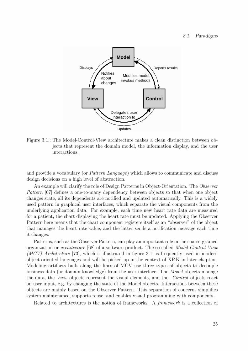
Figure 3.1.: The Model-Control-View architecture makes a clean distinction between ob-jects that represent the domain model, the information display, and the userinteractions.
and provide a vocabulary (or Pattern Language) which allows to communicate and discussdesign decisions on a high level of abstraction.
An example will clarify the role of Design Patterns in Object-Orientation. The ObserverPattern [67] defines a one-to-many dependency between objects so that when one objectchanges state, all its dependents are notified and updated automatically. This is a widelyused pattern in graphical user interfaces, which separate the visual components from theunderlying application data. For example, each time new heart rate data are measuredfor a patient, the chart displaying the heart rate must be updated. Applying the ObserverPattern here means that the chart component registers itself as an “observer” of the objectthat manages the heart rate value, and the latter sends a notification message each timeit changes.
Patterns, such as the Observer Pattern, can play an important role in the coarse-grainedorganization or architecture [68] of a software product. The so-called Model-Control-View(MCV) Architecture [73], which is illustrated in figure 3.1, is frequently used in modernobject-oriented languages and will be picked up in the context of XP.K in later chapters.Modeling artifacts built along the lines of MCV use three types of objects to decouplebusiness data (or domain knowledge) from the user interface. The Model objects managethe data, the View objects represent the visual elements, and the Control objects reacton user input, e.g. by changing the state of the Model objects. Interactions between theseobjects are mainly based on the Observer Pattern. This separation of concerns simplifiessystem maintenance, supports reuse, and enables visual programming with components.
Related to architectures is the notion of frameworks. A framework is a collection of
25

3. Object-Oriented Software Engineering
several components with predefined co-operations between them [148]. Frameworks allowto reuse not only code but architectural design and therefore play an important role inrapid software development.
For the recent decade, Object-Orientation has become increasingly popular for manykinds of modeling tasks and is now the most widely used paradigm for software develop-ment. It allows to build abstractions of the world’s entities quite intuitively, and – althougha certain learning process might be required – often leads to clearly structured models [144,page 135]. Thus, object-oriented models facilitate communication, even between developersand little-trained domain experts [34].
3.2. Processes
In this section, I will evaluate modern software process models in the light of their ability tocope with change, to support communication, and to rapidly provide feedback. I will firstreview systematic engineering approaches (such as the Waterfall Model, Fusion [40], andthe Rational Unified Process [109]) and show that they are often too heavy and inflexiblefor the domain of knowledge-based systems. Then I will introduce the ideas of the recent“light-weight” or “agile” approaches (such as Extreme Programming [8]), which try toachieve a greater flexibility by reducing the cost of change.
3.2.1. Systematic Engineering Processes
In the early decades of computing, software has mostly been created in an ad-hoc fashion.Chaotic software processes typically have a higher risk of failing to meet user requirements,of slipping schedule, of producing defect software, and of leading to systems that are be-coming increasingly hard to maintain [168, 8]. With the goal of reducing this risk, researchand practice of Software Engineering has produced a number of models for structured,systematic development processes [119].
The Waterfall Model
One of the most important achievements of early Software Engineering research was torecognize that software development should be performed in steps, with each step cover-ing a certain development phase [144]. Software development was compared to traditionalengineering disciplines such as civil engineering, in which engineers create a precise design,which is then transformed into a house or bridge [39]. The engineering view assumes thatwell-defined engineering rules and plans exist, which only need to be applied in the correctorder to produce the desired software. Further, engineering assumes that the implementa-tion process itself will be straight-forward, if only the design is correct.
The so-called Waterfall Model follows this engineering metaphor, by guiding the devel-opers systematically through the phases of requirements analysis, design, implementation,
26

3.2. Processes
test, and maintenance. Each of these phases bases on the documents or models pro-duced by its predecessors. Whereas the early analysis and design models only describethe coarse-grained, high-level architecture, the implementation models go into the smallestprogramming language details. Boehm [18] has shown that since the basic architecture isfar more important than the implementation details, wrong decisions made early in theprocess are much more expensive than later decisions. This exponential rise of costs isillustrated in figure 3.2.
Cos
t of C
hang
e
Requirements Analysis Design Implementation Testing Production
Figure 3.2.: Systematic Software Engineering methodologies are based on the premise thatthe impact of design decisions (and the cost of changing them) rises exponen-tially over time.
Although the Waterfall Model is still widely applied, especially by government agenciesand large software procurers [168], its inflexible partitioning of the project into distinctstages is based on simplified assumptions which do not reflect the reality of software devel-opment [144]. It is unrealistic that all documents and models are complete and error-freeupon the first creation. Especially the system requirements are often not clear before thecustomers can put their hands on a system prototype. Therefore, waterfall-based projectstend to do very much rework at the very end [110].
As a response, approaches such as Barry Boehm’s Spiral Model [19] and the V-Model(cf. [168]) strengthen the role of feedback and evaluation of risk in the development process.The major progress of these approaches compared to the Waterfall Model is their capabilityof ruling out sub-optimal alternatives and errors early in the process. Their concepts had asignificant impact on the current generation of systematic engineering methodologies, suchas Fusion and the Rational Unified Process, which are described in the following.
Fusion
Fusion [40] is a detailed and generic object-oriented methodology, which has integrated andextended other existing approaches from the early 1990’s, like OMT [159], Booch [20], andOOSE [90]. The goal of Fusion is to provide a direct route from a requirements definitionthrough to a programming-language implementation. As illustrated in figure 3.3, this
27

3. Object-Oriented Software Engineering
route roughly traverses the cascades of the Waterfall Model, with its analysis, design, andimplementation phases.
RequirementsDocument
Object Model Interface Model
Dat
a D
ictio
nary
Analysis
Design
Implementation
Object InteractionGraphs
VisibilityGraphs
ClassDescriptions
InheritanceGraphs
Program
Subsystem
Decomposition
Figure 3.3.: An overview of the Fusion methodology. Fusion is an example for a method-ology where systematic, comprehensive analysis and design activities are per-formed before coding and testing.
In the analysis phase, the informal requirements documents are translated into a declar-ative description of the desired system behavior. This uncovers the objects and classes inthe system, their relationships, and the operations that the system can perform. The anal-ysis models lay the foundation for the design phase, in which the developers decide howto represent the system operations by the interactions of related objects, and how thoseobjects gain access to each other. The design model is geared to be detailed enough fora relatively straight-forward system implementation in an object-oriented language. ThusFusion can be regarded as a waterfall-based methodology. However, Fusion assumes real-istically that any of the modeling artifacts can change, and therefore allows the developersto iteratively step back to any phase in the development cycle.
Its well-structured process with successive models and comprehensive formal notationssuggests that Fusion is an attractive methodology for projects in which the initial require-ments are relatively fixed. For example, I have applied Fusion for a successful redesign of
28

3.2. Processes
an existing expert system for my Master’s Thesis [100]. However, feedback from industrialpractice (e.g., http://c2.com/cgi/wiki?FusionMethodology) reports that Fusion – aswell as other waterfall-based approaches – requires a considerable overhead to keep thevarious modeling artifacts in sync when requirements or design decisions have changed. Achange in Fusion’s Object Model must be passed on to the Class Descriptions, InheritanceGraphs, and the program – and vice versa. These changes are expensive and slow down theprocess. Therefore, the exponential cost curve from figure 3.2 is not only an assumption,but also a consequence of waterfall-based processes.
To summarize, its lack of support for frequently changing models and the resulting delayof prototypes make Fusion – as well as related methodologies where extensive analysis anddesign processes take place before coding and testing – rather unsuitable for developingknowledge-based systems.
The Rational Unified Process (RUP)
The Rational Unified Process (RUP) [109] is a commercial process product developed andmaintained by the world-leading CASE tool vendor Rational Software Corporation. RUP issupported by the influential “Three Amigos” Booch, Jacobson, and Rumbaugh, who werealso involved in the definition of the Unified Modeling Language (UML, subsection 3.3.1).
RUP is basically a meta-methodology (or process template), which must be adaptedto specific project circumstances. RUP comes with several out-of-the-box roadmaps forvarious common types of software projects. It also defines a uniform terminology forartifacts, activities, roles, et cetera and gives advice on tool use.
With the goal of reducing risk, RUP emphasizes the adoption of certain “best practices”of modern software development [146], such as the use of component-based architecturesand visual modeling. The best practices are applied in an incremental, iterative process, inwhich requirements can be refined as the project evolves. As illustrated in figure 3.4, theprocess is divided into the four coarse-grained phases inception, elaboration, construction,and transition. Each phase is split into one or more iterations, in which activities, such asbusiness modeling, analysis, or implementation, are performed in varying levels of detail.For example, the amount of resources put into testing activities increases, when the projectmoves from the construction to the transition phase.
The beginning of an activity is not bound to the end of another, e.g. design does notstart when analysis completes, but the various artifacts associated with the activities arerevised as the problem or the requirements are better understood. RUP can therefore beregarded as a generalization of the Waterfall Model.
RUP is not meant to be document-driven: Its main artifact must remain, at all times,the software product itself. The documentation should remain lean and limited to the fewdocuments that bring real value to the project from a management or technical point ofview. RUP suggests to edit management artifacts (e.g., business case and status assess-ment), technical artifacts (e.g., user’s manual and software architecture), and requirementartifacts (e.g., the project’s vision).
29

3. Object-Oriented Software Engineering
ManagementEnvironment
Business Modeling
Implementation
Test
Analysis & Design
Preliminary Iteration(s)
Iter.#1
PhasesProcess Workflows
Iterations
Suppo rting Workflows
Iter.#2
Iter.#n
Iter.#n+1
Iter.#n+2
Iter.#m
Iter.#m+1
Deployment
Configuration Mgmt
Requirements
Elaboration TransitionInception Construction
Figure 3.4.: An overview of the Rational Unified Process.
Advantages and Limitations of Systematic Processes
Systematic software processes such as Fusion and RUP are often considered to be heavy-weight processes (cf. e.g., [39]), insofar that they stress the importance of planning, rely onwell-structured processes, and suggest to maintain a considerable amount of modeling arti-facts with traceable cross-references. Industrial experience suggests [119], that medium orlarge projects that do not pay attention to establishing effective processes early are forcedto slap them together late, when it takes more time. Heavy processes are also convenientfor project management, because companies expect explicit requirements to be producedor at least a fixed price and time [155]. A well-defined process which regularly producescomprehensive documentation is controllable and allows to measure success. Furthermore,documentation can be easily communicated and reproduced, especially in spatially dis-tributed, large teams. High-level design models can help to introduce new developers intothe team, because they are easier to grasp than the source code.
Although heavy-weight, phase-oriented processes have these benefits, they also sufferfrom inherent problems. Especially, it is impossible to completely define a complex system,and the user is relatively excluded from the phases [144, page 5]. This is very critical for– typically very complex – knowledge-based systems. Partsch [144, page 10] notes
“The more complex a task, the more difficult to describe it precisely and com-pletely, and thus to get clear objectives. The less clear the objectives, the more
30

3.2. Processes
difficult the communication between the different people involved in the project(e.g., customers, end users, analyzers, designers) [...]”
On a philosophical level, the comparison of software development with conventionaltechnical engineering disciplines is misleading. Oestereich [138, page 19] states
“Since software is more interspersed with human abstractions than other tech-nical systems, its complexity, perfidies, and peculiarities rather resemble thestructures of human organization than typically technical ones.”
Another important problem is that writing and synchronizing the various models anddocuments is a considerable overhead. The cost of change rises with each artifact thathas to be maintained. “Traditional methodologies for software delivery are not geared tothe rates of change and speed necessary today” [84]. Furthermore, software developers areoften not keen on producing and using documentation, so that documents are often poorlywritten [39]. Finally, the amount of modeling artifacts and things to consider for planningmake methodologies such as RUP very complex. The complexity of RUP is manifested bythe fact that the text books on RUP [109, 89] just scratch the surface: Companies thatintend to introduce RUP usually must buy an additional CD-ROM, hire a consultant, andintroduce various development tools as well. A reason for this complexity is that RUPtries to cover all eventualities of any type of project. Although RUP can be adapted andcustom-tailored, team leaders still need to know all of its elements well to make a wisedecision what to choose and what to leave out.
3.2.2. Agile Processes
In the late 1990’s, a group of practitioners and academics such as Kent Beck, AlistairCockburn, Martin Fowler, and James Highsmith began to experiment with so-called light-weight or agile software processes that would not suffer from the negative side-effects andcomplexity of systematic, heavy-weight Software Engineering approaches.
Reducing the Cost of Change
In his influential 1999 book, Kent Beck [8] seriously questions the traditional belief thatthe cost of changing a program necessarily rises exponentially over time (as shown beforein figure 3.2). He asks the following:
“The software development community has spent enormous resources in recentdecades trying to reduce the cost of change – better languages, better databasetechnology, better programming techniques, better environments and tools, newnotations. What would we do if all that investment paid off?” [8, page 23]
The assumption of a considerably flattened – or even asymptotic – cost curve is thefundamental premise of agile processes. If projects succeeded in reducing the cost of change,
31

3. Object-Oriented Software Engineering
they could take an entirely different approach, since much of the overhead produced bytraditional engineering methods would no longer be required (cf. [1]): Instead of writing acomprehensive documentation, they could focus on producing working software. Insteadof relying on strong processes and tools, they could support individuals and interactions.Instead of following a plan, they could respond to change dynamically. Instead of fixingthe system requirements in contract negotiations, they could get the customer on board,and allow her steer the development process according to her changing knowledge.
Therefore, instead of putting most of their resources into comprehensive analysis anddesign activities, which shall help detecting potential errors and problems before they areimplemented, agile processes focus their efforts on producing and maintaining changeablesoftware. However, the somehow revolutionary – but essential – assumption of a flattenedcost curve is doubted by many researchers (e.g., [47]). I will show later which specifictechniques are employed by the existing agile methodologies – and my XP.K approach –for keeping the cost of change low, and point to case studies which provide evidence thatthey work in practice.
Among the most prominent light-weight approaches are Adaptive Software Develop-ment [83], the Crystal Family of Methods [37], and Extreme Programming [8], which isdescribed in the following.
Extreme Programming (XP)
Extreme Programming (XP) [8] was conceived in 1996 by Kent Beck to address the specificneeds of software development conducted by small teams in the face of vague and changingrequirements. In a nutshell, the main idea of XP is to iterate a process in which developersgenerate tests together with the customer, code what is necessary to run those tests, andintegrate the product. XP is based on four values :
• Communication. Many projects fail because a programmer does not tell someoneelse about a critical change or because a knowledge engineer does not ask a domainexpert the right question. Fluent communication supports brain-storming, creativity,and a motivating team spirit.
• Simplicity. XP argues that it is better to do a simple thing today and pay a littlemore tomorrow to change it if demand arises. Beck suggests to ask “What is thesimplest thing that could possibly work?” [8, page 30]. Simple designs are easier toimplement, to change, to communicate, and to understand.
• Feedback. Frequent feedback allows to evaluate designs and makes sure that changesin one part of the system did not damage other parts. Prototypes support communi-cation, especially with customers or domain experts, and allow the management toget a picture of the project’s schedule.
• Courage. XP’s design strategy resembles a hill-climbing algorithm, in which you startwith a simple design, then make it a little more complex, then a little simpler, and
32

3.2. Processes
so on. However, you might reach a local optimum, from which only complex changeswill improve the situation. Applying such complex changes requires courage – alsothe courage to throw away one’s beloved code.
These four values are the long-term goals which development teams should pursue atall times. Based on these values, XP derives several basic principles, which serve as rathershort-term guidelines. The most important of these principles are
• Rapid Feedback. Get feedback, interpret it, and put what is learned back into thesystem quickly.
• Assume Simplicity. Treat every problem as if it can be solved with ridiculous sim-plicity.
• Incremental Change. Don’t risk the overall system by making big changes all at once.
• Embracing Change. Solve the most pressing problem first, but preserve as manyoptions as possible.
• Quality Work. A team doing a good job will most probably enjoy its work.
Beck mentions some more – less central – principles, such as Open, Honest Communi-cation, Teach Learning, Small Initial Investment, and Travel Light. Traveling Light meansto maintain only few, simple, and valuable artifacts instead of a comprehensive monolithicdesign. In XP the source code is the main artifact, and few – if any – other design modelsshould be maintained.
In addition to these rather high-level values and principles, XP is based on the followingpractices, which guide the daily work.
• The Planning Game. The scope of the next release is determined by combiningbusiness priorities and technical estimates. Beck suggests to use simple “story cards”which can be stacked according to their priority.
• Small Releases. Simple versions are put into practice quickly.
• Metaphor. All developers are guided by a simple shared story and vocabulary of howthe system works. The role of the metaphor is comparable to the architecture inobject-oriented design (“the big boxes and connections” [8]).
• Simple Design. The system is designed as simple as possible, so that there are onlyfew models to update on changes. Instead of designing a system that already coversall possible future extensions (“You ain’t gonna need it” [8]), a system should onlycover what is needed “today”, with the option of generalizing it later.
33
3. Object-Oriented Software Engineering
• Testing. The users or customers define and test functional criteria. Programmerscontinually write unit tests to simplify integration and ensure quality. Automatedtest tools (e.g., JUnit [66]) support them. The unit tests also specify and documentthe intended functionality of a program. Beck advises to write the tests prior to theimplementation, so that programmers are forced to define a rudimentary specificationbeforehand.
• Continuous Integration. Code is integrated and tested after a few hours.
• Refactoring [63]. Programmers restructure the system without changing its behaviorto remove duplication, to improve communication, or to add flexibility. Typicalrefactorings are splitting long methods and large classes. Refactoring enables theincremental improvement of simple designs in support of maintainability.
• Pair Programming. All code is written by two programmers at one machine. Whileone programmer implements the current task, the other is thinking more strategically.Pair programming is a dialog at many levels, assisted by and focused on a computer.
• Collective Ownership. Anyone who sees an opportunity to add value to any portionof the code can (and should) do so at any time.
• Coding Standards. Collective ownership requires well-defined conventions for codelayout, naming of variables, amount of documentation, etc.
• 40-Hour-Week. Developers should not work overtime, so that they remain creativeand motivated.
• On-Site Customer. A real customer or user is included in the team, available toanswer questions and evaluate alternatives.
None of these practices is exceptionally new and some practices might remind conser-vative software engineers to plain hacking that has long proven to be obsolete. However,as illustrated in figure 3.5, XP assumes that these practices support each other, so that theweakness of one practice is compensated by the strengths of another. Especially, several ofthe practices, such as Refactoring, Testing, Coding Standards, and Collective Ownership,aim at reducing the cost of change and thus allow to start with a simple design. Thus,the designers of XP claim that an efficient development methodology emerges from thecombination of various simple practices.
Evaluating Agile Processes
Due to their (apparent) ability to cope with change, their support for communication, andtheir focus on feedback, agile processes seem to meet the requirements of knowledge-basedsystems better than systematic, heavy-weight processes. In this document, I will thereforepropose the XP.K methodology, which can be regarded as an agile methodology related
34

3.2. Processes
Planning Game
On−Site Customer
40 Hour WeekMetaphor
Refactoring
Pair Programming
Coding StandardsCollective Ownership Continuous Integration
Short Releases
Testing
Simple Design
Figure 3.5.: The practices of Extreme Programming support each other (figure adaptedfrom [8]).
to Extreme Programming. Of course, prior to being able to proof the benefits of XP.K,I will need to discuss in how far the values, principles, and practices of XP really workas their inventors claim. Due to the limited space, I could only briefly sketch XP. Manyaspects such as the benefits of pair programming and the lack of a well-written designmodel might appear critical and demand further discussion (see [47] for a critics of XP).However, in order to reduce duplication, I will discuss and evaluate details of these issuesin the context of XP.K in later chapters. The arguments for and against agile approacheswill be summarized in chapter 9.
Until then I will assume that XP is a useful technology for a considerably large classof projects. This is stressed by positive feedback from industry [70, 25, 145, 133, 163],where small teams conducting XP style development even outperformed much larger teamsin the same task. However, due to the newness of agile methodologies and the generalproblems of comparing as complex entities as development methodologies reliable dataare still scarce. Independent large-scale evaluations and comparisons against traditionalSoftware Engineering approaches are not available yet [156].
35

3. Object-Oriented Software Engineering
3.3. Languages
Flexible development methodologies for knowledge-based systems should allow the devel-opers to choose any modeling language they prefer. However, the efficiency of a methodol-ogy strongly depends on its interplay with specific modeling and programming languages,because a methodology with concrete guidelines and efficient tools is easier to put intopractice. Although for that purpose it would be possible to use or define a proprietary,object-oriented language that is optimized for the domain of knowledge-based systems,commercially applied standard languages should be preferred. First, relying on standardlanguages makes it easier to recruit teams of developers. Second, widely-used languages willhave a better tool support. Third, the evolution and advancement of successful languagesis secured. Forth, there will be a greater pool of reusable components and libraries.
For these reasons, this section will take a glimpse at the current status quo in object-oriented modeling and programming languages. I will first give a very brief overview ofthe Unified Modeling Language (UML), which is the standard language for object-orientedanalysis and design. This overview will also clarify the syntax and semantics of the variousclass diagrams which appear throughout this document. Then I will outline the meta-modeling language Meta Object Facility (MOF) and its application in the definition ofUML and similar languages. Finally, I will list the currently most important object-oriented programming languages, as of 2001.
3.3.1. The Unified Modeling Language (UML)
In the 1990’s, Object-Orientation was characterized by a confusing number of differentmethodologies. These methodologies did not only strongly diverge in their modeling pro-cesses, but also came with individual modeling languages and notations. Since the differ-ences between these languages were only minor, a group of leading methodologists decidedto join forces under the umbrella of the Object Management Group (OMG) with the goal ofdefining a standard language for object-oriented analysis and design. The resulting UnifiedModeling Language (UML) [21, 64], which is continuously being revised and extended, isnow the de-facto standard language for object-oriented modeling artifacts [122].
UML provides a graphical notation for various types of diagrams. Each of these typescan be used to represent a different view point on the system being developed.
Being the most widely-used type of diagrams, Class Diagrams describe the types ofobjects in the system and the various static relationships that exist among them. Thesyntax of Class Diagrams is illustrated in figure 3.6. Class Diagrams are very popular dueto their intuitiveness, simplicity, and their similarity to the well-known Entity-RelationshipDiagrams [142]. Depending on the perspective and the phase of the modeling process,Class Diagrams can be used in varying granularity (cf. [64]). First, they can be usedinformally to identify the concepts in the domain and their relationships. This simplifiesthe communication between domain experts and engineers. Second, Class Diagrams canbe used to visualize and design the implementation details of the program’s classes.
36

3.3. Languages
Class Name
attribute:Type = initialValue
Operation(arg list): return type
Class
Superclass
Subclass 1 Subclass 2
Generalization
object name: Class name
attribute = value
Object
Class A
Assoziation
Class B
role A
role B
Note{ constraint }
Notes and Constraints
Package
Class 1
Class 3
Class 2
Stereotypes« stereotype name »
Multiplici ties1 exactly one0..1 optionaln..m range* many
Source
Navigabili ty
role Target
Figure 3.6.: An overview of the notation of UML Class Diagrams.
Another important UML diagram type is Use Case Diagrams. A Use Case is a collec-tion of interactions between users (the actors) and the system. Use Cases are a popularmeans of capturing and illustrating requirements. Besides Class and Use Case Diagrams,UML provides additional – less frequently used – types of diagrams to capture the dynamicbehavior of the system. Activity Diagrams are comparable to workflow diagrams, and de-scribe the sequencing of activities, with support for both conditional and parallel behavior.State Diagrams describe all possible states that a particular object can get into and howthe object’s state changes on incoming events. Interaction Diagrams describe how multipleobjects collaborate in some behavior. UML supports two types of Interaction Diagrams:Sequence Diagrams (also known as “swim-lane” diagrams) and Collaboration Diagrams.
UML also provides a formal specification language, called the Object Constraint Lan-guage (OCL) [194], which allows to rigorously define an operation’s purpose and the legalstate of objects. OCL can be used to communicate designs and to validate the executingsystem. However, this language is only slowly gaining acceptance [190].
Since UML is the widely-agreed standard language for the foreseeable future, none of thecurrent methodologies with support for analysis and design activities should neglect sup-porting UML. Knowledge modeling approaches with a high degree of compatibility to UMLcan profit from massive industrial tool support and the other advantages mentioned above.Even the syntax of the leading Knowledge Engineering methodology CommonKADS (seechapter 4) has converged towards UML. This is not surprising, since UML is quite easyto learn, and its visual diagrams (especially conceptual Class Diagrams, Use Cases, andActivity Diagrams [64, page 11]) are adapted for the communication with domain experts.
37

3. Object-Oriented Software Engineering
However, the (increasing) size and complexity UML is often criticized [122, 88]. Only someof its diagram types and only about 20 % of the syntax of Class Diagrams are frequentlyused in the real world [64, 138]. Team leaders are therefore frequently advised to chooseonly a small subset of UML for their projects.
3.3.2. Metamodels and the Meta Object Facility (MOF)
The essentials of visual languages such as UML can be easily communicated informallybetween humans. However, in order to allow computers to automatically process andexchange UML models, a stronger specification of the syntax and semantics of UML isrequired. Furthermore, distributed development teams which cannot profit from face-to-face communication to resolve ambiguities require exchangeable models with well-definedsemantics. As illustrated in figure 3.7, the role of the Meta Object Facility (MOF) [137] isto provide a rigorous metamodel for modeling languages, such as UML – and subsets orextensions thereof.
Meta ObjectFacility (MOF)
M3 LayerMeta−Metamodel
M2 LayerMetamodel
M1 LayerModel
M0 LayerInformation
UMLMetamodel
JavaMetamodel
UML ClassDiagrams
JavaInstances
JavaClasses
Class Att ribute
Symptom
namepackageabstract
nametype
indexed
namedescription
rash: Symptom
name = "Rash"description = "After approx. 3 days, a red blotchy rash starts on the face."
measles: Disease
name = "Measles"cure = AntipyreticsUML
Objects
Class Att ribute
namenametype
evidence−for
evidence−for
Disease
namecure
has−instance
Figure 3.7.: A four-layered metadata architecture of object-oriented systems.
MOF is defined in itself, so that no additional languages above the meta-meta levelare required. MOF can be represented in UML Class Diagrams (an excerpt of this dia-gram is shown in Appendix F). Apart from the UML notation, MOF models can also berepresented textually in a language called XML Metadata Interchange (XMI) [140].
38

3.4. Tools
3.3.3. Object-Oriented Programming Languages
As stated in chapter 2, most useful knowledge-based systems will comprise of modules writ-ten in off-the-shelf software development languages. These are general-purpose languages,which – unlike descriptive or functional languages such as Prolog and LISP, respectively– do not provide explicit support for knowledge modeling or “intelligent” reasoning. Thechoice of an implementation language for the system components that are not directlyinvolved in knowledge processing depends on factors such as legacy system integration,compatibility, personal preferences of the developers, and the availability of tools and li-braries for building user interfaces. Since it is therefore unwise to tie one’s methodologyto one specific language, I will briefly list those languages that a methodology will mostprobably have to cope with in the real world.
Languages such as Smalltalk [114], Beta [117] and Eiffel [125] feature some of thecleanest object-oriented concepts and would provide an interesting platform for knowledge-based systems. Eiffel even supports semantically rich data structures. However, theselanguages are not widely used in industry. On the other extreme, the currently most widelyused languages for desktop applications on Windows – Visual Basic and C++ – can barelybe regarded as object-oriented languages, because they suffer from the heritage of theirimperative predecessors. Recent surveys (e.g., [50, 12]) indicate a significant migration ofdevelopers from these languages to Java [6] and Microsoft’s Java pendant C# [126]. Withalready more than half of the developers using Java regularly, Java is expected to overtakeC and C++ in the year 2002 [65]. The positive acceptance and extensive use of Java inuniversities (including the dominance of Java on leading conferences such as OOPSLA)and the increasing importance of the internet might accelerate this trend.
3.4. Tools
In order to keep this document self-contained, I will now give a short impression of themain features of modern software development tools. This will encompass Integrated De-velopment Environments, which basically add some comfort to plain hacking, and modernCASE tools with support for Round-Trip Engineering between UML diagrams and sourcecode. Both types of tools will be employed by XP.K.
3.4.1. Integrated Development Environments (IDEs)
Integrated Development Environments (IDEs), such as Forte for Java [180] (figure 3.8, left),typically provide features for project management, hierarchical class browsing, source codeediting, compiling, and debugging. Most of these tools also support visual programming ofgraphical user interfaces, including source code generation. IDEs are focused on the codebut relieve the programmer of burdensome standard tasks.
39

3. Object-Oriented Software Engineering
Figure 3.8.: Screenshots of an Integrated Development Environment (Forte for Java [180],left) and a CASE tool with Round-Trip Engineering between UML Class Di-agrams and Java code (Together for Java [184], right).
3.4.2. CASE Tools and Round-Trip Engineering
Whereas IDE’s focus on the implementation phase, CASE (Computer-Aided Software En-gineering) tools support analysis and design activities. As shown in figure 3.8 (right),modern CASE tools are comfortable drawing tools for UML diagrams, especially ClassDiagrams. The resulting models can be exported and distributed in the XMI format.
The major benefit of CASE tools is their coupling of high-level UML diagrams with therespective source code. This coupling is bidirectional: CASE tools can generate the methodtemplates from Class Diagrams (Forward Engineering), but also extract Class Diagramsfrom source code (Reverse Engineering), even if the source code was modified externally.This bidirectional coupling is often called Round-Trip Engineering. It enables developersto arbitrarily switch between programming and designing. This considerably reduces theneed to synchronize the models manually and is therefore a means of reducing the cost ofchange.
Round-Trip Engineering is made possible because UML and object-oriented program-ming languages have a shared set of concepts. Although UML has some shortcomings withRound-Trip Engineering [45], especially with dynamic aspects such as method bodies, it isgenerally straight-forward to find a translation from UML to the programming language.The other way round is harder, because UML concepts, such as relationships, can be im-plemented in many different ways. Therefore, the generated UML models often must beprettified, or even corrected, manually.
40

3.5. Summary
3.5. Summary
This chapter has provided an overview of the paradigms, processes, languages, and toolsof current object-oriented methodologies. There are basically two predominant approachesto the development process, each of which has its individual strengths and applicationscenarios.
Systematic engineering approaches are preferable for projects with rela-tively fixed requirements or large teams. They aim at guiding the teamiteratively from high-level analysis models to a traceable implementation.Powerful CASE tools and the intuitive visual language UML are used to de-sign and communicate models. The main limitation of systematic methodsis their inability to cope with frequent changes in requirements or knowledgemodels.
Agile approaches are increasingly used by projects with weakly-defined re-quirements and small to medium-sized teams. They try to reduce the cost ofchange by consequently keeping plans, design and modeling artifacts small.Their explicit support for evolutionary development and communicationwith domain experts suggest that agile approaches are attractive for thedomain of knowledge-based systems.
Both approaches make use of a major strength of the object-oriented paradigm: Object-Orientation is based on only very few concepts, which pervade through all models andphases of development. Object-Orientation is therefore relatively easy to learn, to commu-nicate, and enables smooth transitions between the models [144].
The main weakness of object-oriented methodologies in the context of knowledge-basedsystems is their missing (explicit) support for knowledge representation and intelligentreasoning, because their processes, languages, and tools are general-purpose. However, inlater chapters on XP.K, I will show that the general-purpose methodologies can be custom-tailored to knowledge-based systems. Before that, I will report on the state-of-the-art inKnowledge Engineering – a discipline with an Artificial Intelligence background, which hasabsorbed many concepts from Object-Oriented Software Engineering.
41


4. Knowledge Engineering
Knowledge Engineering (see [175] or [176] for recent surveys) is often regarded as a mix-ture of Artifical Intelligence and Software Engineering. Knowledge Engineering aims atdefining methodologies that allow to construct knowledge-based systems in a systematicand controllable manner [175].
In this chapter, I will review state-of-the-art methodologies from Knowledge Engineer-ing by their paradigms (section 4.1), process models (section 4.2), knowledge modelinglanguages (section 4.3), and knowledge acquisition tools (section 4.4). I will conclude thischapter with a summary (section 4.5).
4.1. Paradigms
Early research in Artificial Intelligence was focused on the development of “expert systems”that tried to capture domain knowledge by means of primitives such as production ruleswhich were evaluated by rule interpreters. Despite early success with small prototypicalsystems, research in expert systems failed to scale up for large systems, because the rathersimple formalism of production rules did not support an adequate representation of differenttypes of knowledge. “Such a mixture of knowledge types, together with the lack of adequatejustifications of the different rules makes the maintenance of such knowledge bases verydifficult and time consuming” [176]. Furthermore, knowledge encoded in rules is hard toreuse.
In order to overcome these limitations of expert systems, researchers from KnowledgeEngineering suggest to build knowledge-based systems from two kinds of reusable com-ponents: Ontologies and Problem-Solving Methods. Ontologies describe domain knowl-edge in a generic way and provide an agreed-upon understanding of a domain. Problem-Solving Methods describe the reasoning processes of a knowledge-based system in animplementation- and domain-independent manner. In the following, I will introduce thebasic concepts behind these types of components and show their respective roles in a gen-eral architecture of knowledge-based systems. In the later sections, I will show whichmodeling processes, languages, and tools can be used to specify them.
43

4. Knowledge Engineering
4.1.1. Ontologies
The essential promise of ontologies is condensed in the following definition, which is basedon an earlier definition by Gruber [79] and is now widely accepted by the KnowledgeEngineering community (cf. [187, 176, 52]).
Definition (Ontology): An ontology is a formal, explicit specification of ashared conceptualization.
Taken apart, this means the following. Ontologies are formal so that they can beautomatically processed by machines. Ontologies are explicit specifications, i.e. they defineconcepts, properties, and relations explicitly. Ontologies are shared in so far that theyare agreed-upon by various groups of people and that they can be communicated betweenmachines (e.g., in a multi-agent system). Finally, ontologies are conceptualizations, i.e.they are abstract models of some phenomenon in the world.
Ontologies have become a popular research topic in Artificial Intelligence, natural-language processing, knowledge management, and – rather recently – intelligent informa-tion retrieval on the internet. Examples of ontologies include the Yahoo! internet directory,e-commerce standards for data exchange, and the medical structured vocabularies of theSNOMED standard [150].
In the context of knowledge-based systems, ontologies provide a vocabulary of termsand relations with which a domain can be modeled. A major goal of building ontologiesis to enable reuse of knowledge models. In order to do this efficiently, an ontology shouldsatisfy the following design principles (cf. [187, 189]): An ontology should have a highinternal coherence and a low coupling with other ontologies. Ontologies should be modular,extensible, center their definitions around natural categories, have a minimal encoding bias,and a minimal ontological commitment.
4.1.2. Problem-Solving Methods
Whereas the problem-solving behavior of traditional expert systems was encapsulated ingeneric inference engines like rule interpreters, modern Knowledge Engineering approachesagree that reasoning knowledge itself should be made explicit in Problem-Solving Meth-ods [29].
Definition (Problem-Solving Method): A Problem-Solving Method is anexplicit specification of inference steps, a control structure over these steps,and the role that domain knowledge plays in each step.
Figure 4.1 illustrates the inference steps and their control structure of a sample Problem-Solving Method for diagnosis tasks. Each of the inference steps (represented by ovals)receives dynamic knowledge or data from the problem domain as input (e.g., specific patientdata) and produces new knowledge as output (e.g., a hypothesis about a disease). Apartfrom this dynamic knowledge, the steps are further characterized by static knowledge
44

4.1. Paradigms
complaint
cover hypothesis
select
hypothesis specify observable
obtain
findingverify
result
Figure 4.1.: A Problem-Solving Method for diagnosis tasks (adapted from [164]).
about the domain (e.g., the symptoms of diseases). Both roles of knowledge are specifiedby means of generic method or task ontologies [128].
In the terminology of Object-Orientation, Problem-Solving Methods can be regardedas Design Patterns that describe generic components which interact in a controlled order tosolve a task. Each of these components (or inference steps) is defined through its interface,which is a class structure that specifies the syntax and semantics of its input and output.
By explicitly specifying problem-solving knowledge, Knowledge Engineering metho-dologies aim at pursuing three goals [175, 29]. First, the structure of Problem-Solvers canserve as a guideline for the acquisition of static domain knowledge. Second, the reason-ing algorithms are made transparent so that experts can better understand the problem-solving process. Third, reasoning knowledge can be reused because Problem-Solvers arecomponents with well-defined interfaces, functionality, and assumptions [57]. The enablingtechnology behind such reuse is ontology mapping [174]. A mapping defines a translationor bridge [67] from specific domain ontologies to the generic method ontologies.
4.1.3. An Architecture for Knowledge-Based Systems
As illustrated in figure 4.2, ontologies and Problem-Solving Methods are the central com-ponents in a generic architecture for knowledge-based systems (cf. [56, 78]).
Domain ontologies specify the terminology (or the concepts and their relationships) ofthe (static) knowledge base. The ontology is mapped to the Problem-Solvers’ ontologies, sothat the domain knowledge can be processed by the reasoning algorithms. The Problem-Solvers access and modify the dynamic case data, which are also modified by the remainingsystem components and presented to the end users. The user interface may also access the
45

4. Knowledge Engineering
Ontology Problem−SolvingMethod s
KnowledgeBase
User Interface and other Modu les
CaseData
PSM−Ontology
PSM−KBase
StaticMapping
DynamicMapping
Figure 4.2.: A generic architecture for knowledge-based systems.
domain knowledge model, for example to display details of a specific disease and to enablethe user to trace and control the problem-solving mechanisms.
Although this architecture is widely accepted on a theoretical level, it is based on as-sumptions that do not always reflect real-world requirements. In particular, the premisethat ontologies can be designed independently from their potential use in inference algo-rithms has been criticized by Bylander and Chandrasekaran [24]. They state that prior tobuilding ontologies, a clear understanding of the tasks and inferences that the ontology willbe applied to is required. This so called interaction problem has remained an inconvenientissue in modern Knowledge Engineering approaches. To make things worse, its potentialsolution – the use of suitable mapping techniques and guidelines for their application –is recognized as a non-trivial issue and is still a matter of spirited discussion. Even themost prominent Knowledge Engineering approach CommonKADS deals with the mappingproblem only very vaguely and notes “an elaborate description of ontology mappings isthe subject of further research” [164, page 417]. Blaha and Premerlani [14] state that “thetopic of transformations is heavy reading”.
4.2. Process
The dominant view in the Knowledge Engineering literature is that the developmentprocess of ontologies, Problem-Solving Methods, and their relationships should not beperformed in an ad-hoc fashion. “The absence of commonly agreed on guidelines andmethods hinders the development of shared and consensual ontologies within and betweenteams” [74]. If systems are built on a large scale and with some guarantees of correct-ness and completeness, systematic methodologies should be followed. Furthermore, earlierattempts to simply “translate” domain knowledge from human experts onto formal knowl-edge representations are regarded as insufficient, in particular due to the important role of
46

4.2. Process
tacit knowledge for an expert’s problem-solving capabilities [175]. Therefore, KnowledgeEngineering is regarded rather as a modeling process than a transfer process of domainknowledge [129]. Since this modeling process depends on subjective interpretations andis therefore typically faulty, it must run through several iterations and involve evaluationsteps.
Several research groups from the Knowledge Engineering community have proposed de-velopment methodologies for knowledge-based systems (see [115] and [175] for overviews).These groups use different modeling languages and tools, particularly their respective in-dividual research platforms [115], and few of them have been evaluated and widely usedby independent groups [10]. “Knowledge Engineering did not get a widespread attentionin the past” [173].
4.2.1. Ontology Modeling Approaches
Ontologies are the central building blocks of knowledge-based systems and as such demandparticular methodological support. In the following, I will produce a brief yet fairly com-prehensive overview of ontology building methods. Recent surveys of these approaches canbe found in [94] and [115]. The approaches were built by reflecting on practical experi-ence in the construction of specific ontologies and are therefore relatively immature for thegeneral purpose. As a result, ontology building is still rather a craft than an understoodengineering process [94, 74]. However, there is an agreement that ontology constructionshould be harnessed in a step-by-step process that is supported by a succession of interme-diate models and rules of thumb. The approaches also agree to start with informal modelsand to formalize them relatively late in the process.
Interestingly, most of the approaches take a task as the starting point, i.e. they suggestto perform ontology construction with the ontology’s usage scenarios in mind. This makesreuse of the resulting ontologies inherently hard and can be regarded as the defeat in theface of the interaction problem [94].
Uschold
Uschold’s methodology [186] begins with the identification of the purpose of the ontologyand then the key concepts and relationships in the domain. These are first captured inan unambiguous textual form, then mapped onto a precise terminology, and then coded ina formal knowledge representation language and integrated with existing ontologies. Theintegrated ontology is finally evaluated and documented for later modification and reuse.
Gruninger and Fox
Similarly to Uschold’s approach, Gruninger and Fox’s methodology [80] starts with thecapture of motivating scenarios which also clarify the semantics of the later ontologies.The authors then propose to define the competency of the ontology by means of informalquestions that the later system shall be able to respond to. The methodology then lets
47

4. Knowledge Engineering
the developer first produce a semi-formal and then a formal specification of the ontologicalconcepts. The resulting terminology is then used to formalize the competency questionsand the axioms and constraints that declare the semantics of the ontology. These arefinally used to evaluate the system by applying the competency questions.
This approach shows remarkable similarities to the “test-first” development style ofExtreme Programming. The competency questions are comparable to test cases, whichare in XP also envisioned prior to building the respective code and then run by calling the(later implemented) methods.
Methontology
Methontology [15] is more complex than the aforementioned approaches. Beside a waterfall-based development process model, it also identifies project management and support activ-ities. The development itself iterates through the phases specification, knowledge acquisi-tion, conceptualization, integration, implementation, evaluation, and documentation. Likeall the other ontology modeling approaches, it suggests a middle-out strategy, in which themost important domain concepts are modeled first and then refined.
4.2.2. Knowledge Engineering Methodologies
There are very few general-purpose methodologies described in the literature which have abroader scope than the ontology building approaches above and cover the whole softwarelife-cycle.
CommonKADS
By far the most frequently cited Knowledge Engineering methodology is CommonKADS[164]. CommonKADS is the result of various European research projects from the 1990’s.The evolution of the approach has virtually ceased (e.g., as of mid-2001, the official projecthomepage has not been updated for more than one year), but some of its main ideas havebeen adopted by related research projects.
CommonKADS suggests a systematic engineering process in which different modelsare constructed, each of which capturing a specific aspect of the system. CommonKADSapplies the Knowledge Level [132] principle, which states that the knowledge modelingprocess should first concentrate on the conceptual structures and leave the programmingdetails for later. The models in the CommonKADS process are illustrated in figure 4.3.
These models provide a decomposition of knowledge engineering tasks, so that whilebuilding one model, the engineers can temporarily neglect certain other aspects. Althoughthe models can be edited in parallel, the CommonKADS process is rather Waterfall-based,i.e. its models base upon each other.
The central model in the CommonKADS process is the Knowledge Model (sometimescalled the Model of Expertise), which consists of three layers:
48
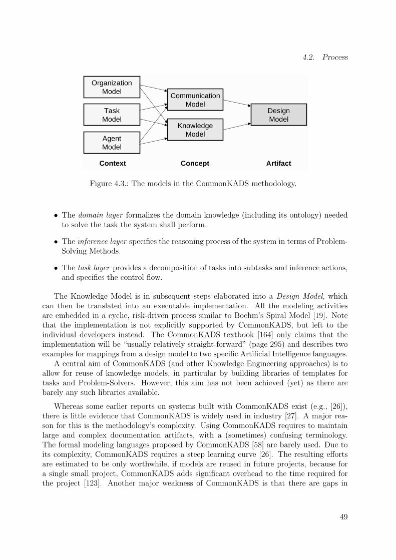
4.2. Process
OrganizationModel
TaskModel
AgentModel
CommunicationModel
KnowledgeModel
DesignModel
Context Concept Artifact
Figure 4.3.: The models in the CommonKADS methodology.
• The domain layer formalizes the domain knowledge (including its ontology) neededto solve the task the system shall perform.
• The inference layer specifies the reasoning process of the system in terms of Problem-Solving Methods.
• The task layer provides a decomposition of tasks into subtasks and inference actions,and specifies the control flow.
The Knowledge Model is in subsequent steps elaborated into a Design Model, whichcan then be translated into an executable implementation. All the modeling activitiesare embedded in a cyclic, risk-driven process similar to Boehm’s Spiral Model [19]. Notethat the implementation is not explicitly supported by CommonKADS, but left to theindividual developers instead. The CommonKADS textbook [164] only claims that theimplementation will be “usually relatively straight-forward” (page 295) and describes twoexamples for mappings from a design model to two specific Artificial Intelligence languages.
A central aim of CommonKADS (and other Knowledge Engineering approaches) is toallow for reuse of knowledge models, in particular by building libraries of templates fortasks and Problem-Solvers. However, this aim has not been achieved (yet) as there arebarely any such libraries available.
Whereas some earlier reports on systems built with CommonKADS exist (e.g., [26]),there is little evidence that CommonKADS is widely used in industry [27]. A major rea-son for this is the methodology’s complexity. Using CommonKADS requires to maintainlarge and complex documentation artifacts, with a (sometimes) confusing terminology.The formal modeling languages proposed by CommonKADS [58] are barely used. Due toits complexity, CommonKADS requires a steep learning curve [26]. The resulting effortsare estimated to be only worthwhile, if models are reused in future projects, because fora single small project, CommonKADS adds significant overhead to the time required forthe project [123]. Another major weakness of CommonKADS is that there are gaps in
49

4. Knowledge Engineering
the transitions between the phases and models. “A common problem concerns the trans-formations of the high-level conceptual model into a particular implementation platform,such as for example an object-oriented environment or rules” [10]. Concrete guidelines andsoftware support is missing. In the face of these disadvantages, it is frequently mentionedthat CommonKADS does not need to be used in its entirety to be useful.
MIKE
The MIKE approach [4] has been developed at the University of Karlsruhe in the mid-1990’s. It covers all steps from requirements elicitation through specification to designand implementation. MIKE integrates semi-formal and formal specification techniquesand prototyping into an incremental and reversible system development process. Its cen-tral modeling artifact is a knowledge model very similar to the Model of Expertise fromCommonKADS. In contrast to the latter, MIKE attempts to achieve smoother transitionsfrom informal to formal, executable models. However, it uses very specialized modelinglanguages and tools which are virtually not used outside of the authors’ research labora-tories. Therefore, since the end of this project’s funding, there are no noteworthy reportsabout industrial applications.
Protege
A frequently mentioned Knowledge Engineering method is Protege [78] from Stanford Uni-versity. The focus of this approach is the construction of knowledge acquisition tools insupport of evolutionary knowledge acquisition. Protege can be regarded as an implemen-tation of the generic architecture of knowledge-based systems from figure 4.2, insofar thatit supports the rapid development of ontologies and knowledge bases which instantiatethem. The approach makes little assumptions about how the ontologies are constructedbut provides an efficient modeling tool (see subsection 4.4.1) which is widely used in theKnowledge Engineering community and (apparently) also outside of research labs. Protegealso supports the idea of ontology mappings as a means of accessing and reusing Problem-Solving Methods, but provides only few guidelines for their construction [135]. Protegecan therefore hardly be called a methodology, unless a very light one.
4.3. Languages
Research in knowledge representation has produced many languages to describe and for-malize ontologies, Problem-Solving Methods, and their relationships. Recent overviews ofthese languages can be found in [41] and [52]. The languages are still evolving, particularlyin the face of new requirements arising with the advent of the “semantic” internet [170].
Early knowledge representation approaches such as KIF [69] were based on pure first-order predicate logic. These languages have great expressiveness, but suffer from beinginefficient and semi-decidable, and from lacking features to express procedural knowledge.
50

4.3. Languages
Furthermore, first-order logic is hard to read, communicate, and comprehend. Formalmodels are notoriously difficult to build [71].
As a result of these weaknesses, alternative forms of knowledge representation have beenproposed, in particular frame-based languages, which organize knowledge in class struc-tures similar to those from Object-Orientation. The idea of frames dates back to MarvinMinsky [127], but was also influenced by early work on object-oriented languages such asSIMULA. The frame-based approach has been further developed into F-Logic [97] and isimplemented by more than 50 ontology specification languages such as Ontolingua [79],XOL [96], LOOM [116], the CommonKADS modeling language [164], and the most recentincarnation of “emerging ontology standards” called OIL [54].
The common elements of most frame-based languages are summarized by the OpenKnowledge Base Connectivity (OKBC) [30], which provides a generic protocol to accessand exchange knowledge expressed in various frame-based languages. As such it has anextremely general knowledge model and makes minimal knowledge-representation commit-ments. However, OKBC covers the by far most important aspects of frames and is thereforevery popular on its own and not only as an exchange language. OKBC is now a de-factostandard which has for example been adopted by the FIPA [59] consortium for the ex-change of ontologies between agents and as the underlying knowledge model of the Protegesystem [135]. Since OKBC is a representative of a large class of ontology specificationlanguages, I will provide an overview of it in the following subsection. In later chapters, Iwill show that OKBC can – partially – be mapped to Java classes. This mapping is at thecore of KBeans, the ontology language of the XP.K methodology.
4.3.1. Ontology Specification with OKBC
The building blocks of the OKBC knowledge model [30] are illustrated in figure 4.4. Aknowledge base is a collection of frames. A frame is either an instance, a class, a slot,or a facet. Classes are concepts in the domain of discourse. Slots describe propertiesor attributes of classes and instances. Slots are first-class objects, i.e. they can existwithout being attached to a specific other frame. Slots are either primitive or non-primitive.Primitive slots can take values of the basic data types (integers, floating point numbers,strings, and booleans). Non-primitive slots represent a relation between two frames. Facetsdescribe properties of slots, in particular constraints on the valid values. All frames areinstances of one or more classes. In several implementations of OKBC, e.g. Protege, framesare instance of exactly one class only. Although classes are themselves instances, i.e. meta-classes exist, knowledge bases are usually treated to consist of two disjoint partitions,namely the classes (the ontology) and the instances [136].
Classes constitute a taxonomic hierarchy with inheritance defined as in object-orientedlanguages (but with multiple inheritance). Slots can also be arranged in an inheritancehierarchy. OKBC distinguishes between so-called own slots and template slots. Own slotscan be attached to any frame and store a set of values to describe the frame. Every ownslot is related to one template slot. Template slots are attached to classes and describethe type and default values of own slots. Whenever an instance of a class is created, its
51

4. Knowledge Engineering
Frame
name: String
Instance
Class SlotFacet
type: FacetType
KnowledgeBase*contains
ownSlots
type*
1
subClass
+*
ownFacets
superClass
inheritance
**
templateFacets*
templateSlots
**
*
NonPrimitiveSlot
*
*
PrimitiveSlot
type: ValueTypeallowedClasses
+
*
subSlot
+*
inheritance
superSlot
Figure 4.4.: The metamodel of OKBC (as implemented in Protege) in UML notation.
own slots “inherit” the values of the class’ template slots as default values. Thus, templateslots can be regarded as declarations of own slots on class level.
Every frame/slot pair can be further described by a set of facets. Facets providemetadata about slots. They can be used to constrain the space of admissible values ofa slot. Facets can only be attached to slots of certain value types. Facets are typedand OKBC defines a list of standard facet types with predefined semantics to cover themost frequently needed kinds of metadata about slots (summarized in table 4.1). Forexample, facets can be used to constrain the maximum number of values a slot can have(:MAXIMUM-CARDINALITY), to specify the numeric minimum of a primitive slot (:NUMERIC-MINIMUM), and to declare that a given slot must contain a subset of the values of anotherslot (:SUBSET-OF-VALUES).
Whereas frames can be used to declare structures, many ontology languages also pro-vide support for expressing semantic relationships between frames, especially axioms, rulesand functions. Traditional knowledge representation languages capture these semantic re-lationships by means of sentences in predicate logic, frequently written in the LISP-likeprefix notation of KIF [79]. However, predicate logic allows for many syntactic variationsto denote the same semantic meaning of an axiom and has other disadvantages as describedbefore. Furthermore, whereas frames can be nicely visualized as conceptual graphs, textualformulae are hard to edit during knowledge acquisiton (in particular if the acquisition isperformed by domain experts). Therefore, many ontology languages such as OKBC pro-vide barely any support for axioms or rules. There exist alternatives for the specification
52

4.3. Languages
Table 4.1.: The constraining facets of OKBC.
Facet name Facet type Semantics:VALUE-TYPE class Type restriction on the values of the slot.:INVERSE slot Any value is also a value of the specified slot.:CARDINALITY int (≥0) Exact number of values.:MAXIMUM-CARDINALITY int (≥0) Maximum number of values.:MINIMUM-CARDINALITY int (≥0) Minimum number of values.:SAME-VALUES slot chain Values are equal to values of specified slot.:NOT-SAME-VALUES slot chain Values are not equal to values of specified slot.:SUBSET-OF-VALUES slot chain Values are a subset of specified slot.:NUMERIC-MINIMUM number Inclusive lower bound of value (≥).:NUMERIC-MAXIMUM number Inclusive upper bound of value (≤).:SOME-VALUES <type>[] Enumeration of valid values.:COLLECTION-TYPE {set, list, bag} Values are treated as set, list, or bag.
of these elements with frames only. First, one can map the meta language of logic ontoframes, so that axioms are themselves implemented by special frames such as quantifiersand operators. I will provide an example for such a frame-based axiom language in chap-ter 8.1. Second, it is possible to classify axioms into axiom types as described in [171] andthen describe axioms as complex objects that refer to concepts and relations. This is verysimilar to the way of specifying semantics with facets.
The purpose of most ontology languages is to inherently support various types of rea-soning, so that new knowledge can be generated from existing knowledge without havingto translate the knowledge into a different format first. As illustrated in figure 4.5, frame-based languages allow for the use of classification (to find the class of a given instance),constraint checking (to check whether a given instance violates any of the constraints de-fined for its class), and rule chaining (to derive new facts from an existing knowledgebase).
Note that these types of reasoning differ from the concept of Problem-Solving Methods:Problem-Solvers are on a more general level and may use the low-level reasoning methodsinternally. Apart from these built-in reasoning services, some languages allow to implementprocedures which can be used to integrate ontologies much closer into the other modulesof the knowledge-based system they are embedded in.
To summarize, there is a wide consensus that frames are currently the most efficientmeans of representing ontologies. Like objects from Software Engineering, they are rela-tively close to human intuition and thus easier to build and comprehend than pure logic-based languages. Frames thus meet the criteria defined in section 2.3 (adequate, easy tolearn, translatable, incremental, precise, complete, and compatible) relatively well. Thereare noticeable similarities between object-oriented and frame-base languages. In a nut-shell, ontology languages can be regarded as object-oriented languages minus methods
53

4. Knowledge Engineering
Knowledge Representation Reasoning Support
Frame−Based OntologySpecification Langu ages
Classes
Inheritance
Slots / Attributes
Facets
Procedures / Integrationwith other languages
Relations / Functions
Instances / Facts
Axioms
Production Rules
Classification
Execution ofProcedures
Rule Chaining(Backward / Forward)
Constraint Checking
Figure 4.5.: Common knowledge representation and reasoning capabilities of frame-basedontology specification languages (figure based on [41]).
plus primitives for describing axiomatic rules or consistency conditions (cf. [5, 164, 43]). Iwill later discuss the differences between the two domains and argue that these differencesare in many cases so minor that an object-oriented language such as Java only has to beextended slightly so that it suffices for knowledge representation.
4.3.2. Languages for Problem-Solving Methods (UPML)
Beside ontologies, Knowledge Engineering suggests to build systems from Problem-SolvingMethods. For more than a decade, there have been various attempts to define methodspecification languages (see [188] for an overview), for example the CommonKADS knowl-edge specification language CML [164] and MIKE’s language KARL [53]. However, theselanguages are virtually not used outside their inventor’s research labs. Recently, a large con-sortium of internationally renowned researchers has developed the Unified Problem-SolvingMethod Development Language (UPML) [56], which can be regarded as the state-of-the-artin this area. In the following, I will provide a brief overview of this language.
UPML assumes an architecture of knowledge-based systems which consists of the threeelements tasks (problem types), Problem-Solving Methods, and domain models. Thesethree elements share a common ontology, which specifies their terminology. In supportof reuse, tasks, methods, and domain models are relatively independent from each otherand adapters are used to specify mappings between them. UPML supports two types ofadapters, namely bridges and refiners. Bridges explicitly model the relationships between
54

4.4. Tools
two parts of the architecture, e.g. by matching input and output between the domain modeland a method. Refiners can be used to express a stepwise adaptation of elements, e.g. aProblem-Solver is refined by means of an inheritance and overloading mechanism knownfrom object-oriented languages.
UPML does not prescribe a specific ontology representation language but refers to exist-ing frame-based or logic-based standards. However, it does provide semi-formal specifica-tion languages for the three architectural elements. Tasks are specified by their ontology, in-put and output roles, goal, preconditions, and assumptions. Domain Models are describedby their ontology, properties, assumptions, and domain knowledge (rules). Problem-SolvingMethods are defined by their ontology, input and output roles, pre-conditions, subtasks,post-conditions, and control flow. By providing these information, UPML aims at sup-porting the construction of catalogs of tasks and methods which solve them.
Although its language is rather abstract and not sufficiently formal to allow for a directimplementation, UPML proposes some design patterns for the implementation of UPMLmodels in object-oriented languages. Here, every UPML Problem-Solver is mapped toone (Java) class, which communicates with other modules using specific bridge objects.Ontologies and domain models are mapped to an ordinary class hierarchy, which definesthe basic terminology used in the domain models and methods. Refiners are implementedby method inheritance. This UPML-to-Java mapping is quite interesting for the KBeansapproach described in chapter 6, because it admits that the gap between the Knowledgeand Software Engineering world is not that large after all. I will pick up this issue later.
4.4. Tools
The forth pillar of methodologies is tool support. In the context of Knowledge Engineering,tool support is essential for the construction of ontologies and domain knowledge bases,and for their evaluation. An overview of existing knowledge acquisition tools is providedby [46]. These tools are mostly prototypes which were built to support the KnowledgeEngineering approach or ontology language of the respective research group. From these,only Protege-2000 [78] appears to be seriously used in real-world projects. Since Protege-2000 has also received the best rating in [46] and because I will pick up several of its ideasin chapter 7, I will in the following provide an overview of this tool.
4.4.1. Protege-2000
Protege-2000 [78] is the latest generation of a series of knowledge acquisition tools devel-oped at Stanford Medical Informatics. Whereas older versions were native applications forWindows and NeXT platforms, resp., the current tool is written in Java. Protege-2000 is anOKBC-based knowledge acquisition tool. As such, it is based on a relatively strict separa-tion between ontologies (classes) and domain knowledge (instances). Knowledge engineerswho employ the tool first use the hierarchical class editor to define the ontological concepts,their slots, and their facets. Based on this ontology, the system automatically creates a
55
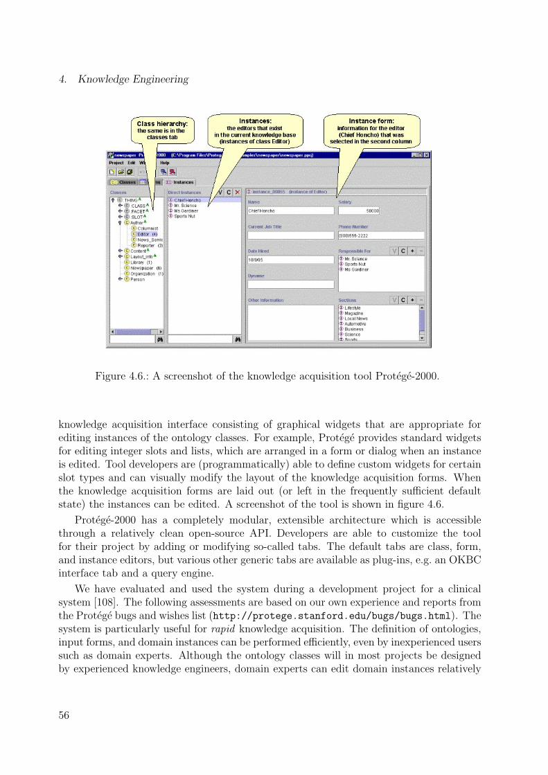
4. Knowledge Engineering
Figure 4.6.: A screenshot of the knowledge acquisition tool Protege-2000.
knowledge acquisition interface consisting of graphical widgets that are appropriate forediting instances of the ontology classes. For example, Protege provides standard widgetsfor editing integer slots and lists, which are arranged in a form or dialog when an instanceis edited. Tool developers are (programmatically) able to define custom widgets for certainslot types and can visually modify the layout of the knowledge acquisition forms. Whenthe knowledge acquisition forms are laid out (or left in the frequently sufficient defaultstate) the instances can be edited. A screenshot of the tool is shown in figure 4.6.
Protege-2000 has a completely modular, extensible architecture which is accessiblethrough a relatively clean open-source API. Developers are able to customize the toolfor their project by adding or modifying so-called tabs. The default tabs are class, form,and instance editors, but various other generic tabs are available as plug-ins, e.g. an OKBCinterface tab and a query engine.
We have evaluated and used the system during a development project for a clinicalsystem [108]. The following assessments are based on our own experience and reports fromthe Protege bugs and wishes list (http://protege.stanford.edu/bugs/bugs.html). Thesystem is particularly useful for rapid knowledge acquisition. The definition of ontologies,input forms, and domain instances can be performed efficiently, even by inexperienced userssuch as domain experts. Although the ontology classes will in most projects be designedby experienced knowledge engineers, domain experts can edit domain instances relatively
56

4.4. Tools
straight with only little training. Protege meets the quality criteria defined in section 2.3insofar that it is easy to use, flexible, adaptable, explorative, and enjoyable to use.
Some shortcomings of Protege-2000 are due to its status as a non-commercial researchprototype with limited funding (e.g., missing undo functionality, various bugs, some ugli-ness). A rather inscrutable limitation is that although the standard facet types of OKBCare implemented they are not used during knowledge acquisition. In particular, facet-basedconstraint checking could be used to detect inconsistencies, to report them to the knowl-edge modeler, and thus to guide user input. Another weakness of the system that we foundvery inconvenient during knowledge acquisition is the generic visual display of instances,in which instances are represented by generic names (e.g., “person 023”) instead of rathersuitable adaptive ones (e.g., “Adam”). This is particularly relevant when instances arecomplex, such as expression trees representing rules and axioms. Furthermore, the defaultknowledge acquisition widgets are seldom sufficient. Many projects have knowledge baseswith graph-like structures such as process models or flowcharts, or rule-based elements.These projects will typically have to implement their own (graph and rule) editors. Thevery idea of allowing the knowledge engineers to modify the classes frequently and at anytime hinders the development of customized widgets. In realistic projects, the rate ofchanging the class structure will have to be reduced.
In my opinion, the main weakness of Protege-2000 (and all the other classical KnowledgeEngineering approaches) strikes when the ontologies and domain instances are integratedwith the knowledge-based system. I argue that an ontology can hardly be built in isolation,without having its functionality within the overall system in mind. Figure 4.7 shows thetypical interactions of knowledge modeling components with their software environment(e.g., in our clinical decision support system ANIS [108]).
Decision−Support in theAnesthesia Information
System ANIS
Devices Drugs
Observables Rules
Patient RecordGUIs
Agents Plans
Figure 4.7.: The reasoning capabilities of knowledge-based systems are typically embed-ded into a software environment consisting of modules written in traditionallanguages.
For example, classes such as Symptom and Observation also have their counterpart inthe (Java) implementation, e.g. they must be connected to the classes and user interfaces
57

4. Knowledge Engineering
that deliver and display the respective patient data. Complex instances which representsemantic relationships such as rules will also need to be connected to evaluating methods,especially in the context of method ontologies. Furthermore, a mix of classes that repre-sent knowledge and those that represent case data is frequently needed (e.g., a Patient
class). Finally, Java-based custom editors also need some hard-coded access to the ontologyclasses.
These issues make the transition between the knowledge model and the executableapplication very complicating and require major (code) duplication. The proposed solu-tion of applying bridges or mappings between domain and method ontologies only delaysthe problem and writing efficiently maintainable mappings is not sufficiently understoodyet [164]. As a result, mappings would need to be hard-coded in a programming language.The origin of these problems is that the Protege knowledge model is implemented as anActive Object Model [61], in which classes are themselves objects. Whereas this providesa great flexibility, it also requires translations and duplications, which in turn result inconsiderably high costs of change. I will later tackle this problem by mapping the ontologyclasses directly to Java classes.
4.4.2. Other Tools
The certainly most frequently used knowledge acquisition tools are pencil and paper. Inparticular for early drafts and brain storming sessions, these simple and intuitive toolsare sufficient. Advocates of recent light-weight software development methodologies evenargue that little else is needed apart from paper and code [3]. For the later project phases,the technical successors of pencil and paper, such as Microsoft PowerPoint, Visio and otherdrawing tools, are frequently used. Visio even allows to enrich drawing elements with datastructures (i.e., classes with attributes of primitive types). Since these data structures can(theoretically) be exported to other formats, Visio can well be regarded as a knowledgeacquisition tool, in particular one that profits from massive commercial support. However,it can only extremely hardly be adapted to specific editing needs and lacks support forother editors than graphs.
4.5. Summary
To summarize this brief review of Knowledge Engineering, I will compare its methodologiesto those from Object-Oriented Software Engineering. Although the text books from theareas of Software and Knowledge Engineering express a strict separation between the areasand there are few cross-references between the domains [5] there is a clear overlapping.
In contrast to Object-Orientation, the generic architecture of knowledge-based systemsproposed by Knowledge Engineering separates data (ontologies and domain knowledge)from behavior (Problem-Solving Methods). It is hoped to be able to link the two aspectsonly through the input and output ontologies of the Problem-Solvers. However, the (widelyrecognized) interaction problem [24] suggests that a clear separation of data and methods
58
4.5. Summary
might be rarely possible.Most Knowledge Engineering methodologies rely on very systematic, waterfall-based
processes. Various guidelines for a step-by-step path from informal requirements to exe-cutable models exist and are particularly valuable for inexperienced knowledge engineers.However, processes such as CommonKADS [164] are quite heavy-weight, i.e. they have asteep learning curve and involve the maintenance of many modeling artifacts. The tran-sitions between those artifacts are expensive [10] and neither supported by methods nortools. Interestingly, one of the few relatively successful Knowledge Engineering approaches,Protege, is rather light-weight, explorative, and supported by tools.
The languages promoted by Knowledge Engineering approaches are mostly frame-basedand thus resemble the object-oriented view. However, they have richer means of specifyingstatic models. Especially they have primitives for the explicit declaration of semanticconstraints. At the same time, they suffer from being hard to integrate with the softwarearchitectures of the remaining systems. Therefore they require additional translations andduplications, which in turn result in high costs of change.
The most obvious difference between Knowledge and Software Engineering technol-ogy is that Knowledge Engineering approaches are virtually not used in industry, evenfor the construction of knowledge-based systems [5]: The concept of generic Problem-Solving Methods mostly exists on paper only and few knowledge acquisition tools haveoutgrown the prototypical stage. Instead, systems are usually built on code level, withoutcomprehensive analysis and design methods, and with tools and languages from SoftwareEngineering. Development tools such as expert system shells are – if at all – used for earlyanalysis phases and prototyping, but the executable system is frequently re-implementedin a more mature and flexible object-oriented platform [148].
The consequences of the limited success of their methodologies are recognized by thecommunity’s members themselves. “The Knowledge Engineering community will haveto put more effort in cooperating with other disciplines for making their methods andtools more widely known and available” [173]. “Efforts are required along the lines ofunifying methodologies to arrive at a situation resembling Software Engineering” [115].In this spirit, the XP.K methodology attempts to reduce the gap between Software andKnowledge Engineering. I will provide an introduction to XP.K in the following chapter.
59


5. Overview of the XP.K Methodology
The previous two chapters have identified and compared the basic concepts of Object-Oriented Software Engineering and Knowledge Engineering. The major results were:
• Object-oriented technology is considerably more mature and accessible than Knowl-edge Engineering approaches, but lacks (explicit) support for knowledge modeling.
• Knowledge Engineering research has produced methods and prototypical tools forknowledge acquisition, but suffers from providing little support for the transitionsbetween the various models and components.
In this chapter, I will provide an overview of XP.K, a light-weight methodology for thedevelopment of knowledge-based systems. My goal with XP.K is to help make the develop-ment of “real-world” knowledge-based systems more efficient. In order to yield a pragmaticdevelopment approach, I have based XP.K as close as possible on industrial software tech-nology. XP.K combines approaches from Software and Knowledge Engineering, so thatthe weaknesses of one “world” are covered by the strengths of the other. Thus, XP.K isbasically an extension of object-oriented standard technology by sub-processes, languageelements, and tools to cover the specific requirements of knowledge modeling. In order tomeet the previously identified requirements of a feedback-driven, communication-intensive,evolutionary development process, XP.K is an agile methodology which extends ExtremeProgramming (XP) [8].
Figure 5.1 provides a brief overview of the XP.K process of developing knowledge-basedsystems. The process relies on communication instead of comprehensive documentationor other artifacts. Starting with a small selection of artifacts such as story cards (usecases) and knowledge protocols (expert interviews), domain experts and knowledge en-gineers collaborate to define an initial domain ontology, which is a compromise betweenthe informal domain view and the executable system’s view. The ontology is modeledin a simple subset of UML with additional declarative elements like constraints, whichexpose the model’s semantics to other humans and computers. The shared ontology isthe core model in the system, since it defines the knowledge acquisition vocabulary but isalso accessed by other modules such as Problem-Solving Methods, GUIs, etc. The ratherconceptual, high-level UML model is automatically forward-engineered into (Java) sourcecode, but can be re-extracted at any time by means of Round-Trip Engineering technol-ogy. The Java code is enriched by test code and semantic constraints which support the
61

5. Overview of the XP.K Methodology
modeling process and reasoning algorithms. The domain experts use a generic tool forknowledge (instance) modeling. The tool uses the semantic transparency provided by theontology (using a technology called reflection) for the automated generation of suitableeditors (trees, tables, forms) and for constraint checking during knowledge acquisition.The developers meanwhile enrich the ontology classes to integrate them with the desiredreasoning functionality, e.g. by building subclasses of existing inference classes or by im-plementing suitable mappings to them. Prototypes are produced frequently and exposedto tests and simulations.
Domain experts
KBS / Prototype
Knowledge Model
DomainOntology
KnowledgeBaseD
omai
n V
iew
Sys
tem
Vie
w
Other Modules
Problem−Solvers
Ontology
KBase
Mapping /Subclassing
System developers
KnowledgeProtocols
(Semi−formal)
Knowledge Acquisition
System Development
Evaluation
StoryCards
Knowledge engineers
Test Cases
Figure 5.1.: The XP.K development process.
In the following, I will provide details on the paradigms (section 5.1) and processes(section 5.2) of XP.K. Then, I will introduce languages (section 5.3) and tools (section 5.4)which can be used to put XP.K into practice. Details on these languages and tools areelaborated in chapters 6 and 7. Note that in this chapter, I will not discuss potentialproblems and pitfalls of this methodology, because benefits and limitations will becomeclearer after the details and case studies have been introduced. An evaluation of XP.Kwill follow in chapter 9, which will also identify the problem domains for which XP.K issuitable.
62

5.1. Paradigms
5.1. Paradigms
The basic paradigms of the previously described methodologies are Object-Orientation(including objects, components, patterns, architectures, and frameworks) and the genericarchitecture of knowledge-based systems (including ontologies and Problem-Solving Meth-ods).
I argue that a principal weakness of Knowledge Engineering approaches is to treatknowledge modeling in relative isolation from the remaining application system. As aresult, the transitions between the knowledge models and the executable modules are diffi-cult. I have already indicated in figure 4.7 (page 57) that knowledge-processing componentsrequire efficient access to resources written in general-purpose languages like Java. Usingtraditional Knowledge Engineering approaches, this makes it necessary to build hybridsystems, which mix multiple paradigms, languages, and tools, which are hard to maintainand contain various redundancies. Hybrid systems may also suffer from the typical lowperformance of Artificial Intelligence languages [148].
Another practical obstacle of using Knowledge Engineering technology on a large scaleis that industrial standard languages and tools are missing and that languages are notcompatible to each other. Both weaknesses lead to relatively high costs of developing andchanging knowledge-based systems.
Instead of focusing on the knowledge model as the central part of a knowledge-basedsystem, I regard the knowledge model as only one of several other important models. Forall these other models (user interface, data management, network infrastructure, etc.), theindustrial standards are object-oriented languages and tools, and supporting processes.Thus, the integration of object-oriented technology can not be ignored in knowledge-basedsystems.
It is fair to ask why developers should rely on special knowledge representation systemsat all. “Many of the benefits of knowledge representation systems occur during the processof designing an ontology. This support is undoubtly useful, but in the object-oriented worldthere is also much support available for the design of models, with mature and commonlyused languages, methodologies and tools available” [43]. Is it possible to simply assumeObject-Orientation as the starting point and integrate the essential ideas of KnowledgeEngineering into it, so that a consistent methodology emerges? I think so.
Let us reconsider the requirements for development methodologies defined in chapter 2.As illustrated in the left part of figure 5.2, the basic requirements identified there were thata methodology should support feedback, change (evolution), and collaboration efficiently.
Supporting feedback requires efficient tools and rapid turn-around times between high-level models and executable code. Supporting evolution requires the modeling artifacts tobe maintainable, so that the costs of change are low and that prototyping does not lead toexpensive development dead-ends. Supporting collaboration requires modeling languagesthat are easy to communicate to and between domain experts, but yet sufficiently formalto be useful to developers. My main approach to meet these requirements is that thedevelopment process should center around a single shared modeling artifact, more precisely
63

5. Overview of the XP.K Methodology
Feedback−driven
Evolutionary
Collaborative
Rapidly executable
Maintainable
Simple yet formal
Simple OO withSemantic Transparency
Shared models butindividual views
Figure 5.2.: In order to support feedback-driven, evolutionary, collaborative developmentprocesses, XP.K relies on simple object-oriented models which expose theirsyntax and semantics to humans and machines, so that each group of devel-opers can extract individual views.
an object-oriented domain model (ontology). This model is directly executable, supportedby standard tools, and maintainable by applying best-practices of Object-Orientation.Objects are relatively close to the domain expert’s way of thinking but do not suffer frombeing as “distant” from executable code as traditional knowledge modeling languages. Allgroups of developers access different aspects of this model through different views : Domainexperts only get to see the high-level concepts, relationships and knowledge bases, whereasthe system developers focus on the integration of these concepts with the overall softwarearchitecture. In order to provide details on how this is approach could work, I will take adeeper look at the differences between objects and ontologies in the following.
5.1.1. Differences between Object-Orientation and Ontologies
As already indicated in section 4.3, there is a large overlap between the concepts of objectsand frames. The similarities between both worlds become most obvious if we compareontologies with object-oriented domain models as in the Model-View-Control Architecture(figure 3.1 (page 25)). Both types of models are abstractions of a given domain. The designprinciples for class models are almost identical to those from ontologies (cf. section 4.1.1):Modularity, high internal coherence but low coupling, extensibility, minimal encoding bias,and the use of natural categories and names.
Figure 5.3 illustrates how the basic modeling primitives of ontology and object-orientedlanguages are related to each other. Ontologies are purely declarative, i.e. they only de-scribe concepts and the relationships between them. Ontologies and object-oriented lan-guages have very similar approaches for the declaration of static structures, namely classes(concepts), class hierarchies (using inheritance), attributes, relationships, and instances.
Despite these similarities, there are significant differences in the representation of se-mantics. Ontologies use constraints (metadata on slots), axioms, and rules, whereasObject-Orientation relies on methods (sequences of imperative commands). Both ap-proaches are equally expressive, but a declarative approach is better suited for domainmodeling than an imperative approach. An example will clarify this.
Figure 5.4 shows a simple domain model representing family relationships. The class
64

5.1. Paradigms
Ontologies Object−Orientation
Classes
Instances
MethodsAxioms
Constraints
Attributes Relationships
Class Inheritance
Rules
Semantics(Declaratively)
Static Structure(Declaratively)
Semantics(Imperatively)
Figure 5.3.: The central modeling primitives of ontologies and object-oriented languages.
diagram shows that even simple domain models can be based on a considerable amountof semantical assumptions. These assumptions are important, because they constrain thespace of valid application scenarios, and thus allow to use and reuse models safely andefficiently. However, when class models such the example presented in figure 5.4 are im-plemented in an imperative object-oriented language like Java, their original semantics areusually obscured behind non-transparent programming primitives. The constraint that aperson’s age must not be negative might be implemented by if-clauses that reject negativevalues before they are assigned to the age attribute (e.g., in the setAge method). The con-straint that a person’s marital status must be one of three predefined constants might beimplemented by three appropriate radio buttons. Thus, the semantics are typically imple-mented implicitly, especially by making sure that any execution path through the programwill result in valid object states. The complexity of potential execution paths often leadsto systems that are error-prone, hard to understand and maintain, and almost impossibleto reverse engineer [45]. Most importantly for knowledge-based systems, domain modelsimplemented this way can hardly be used for the explicit representation and exchange ofknowledge, and for knowledge-based reasoning tasks.
The origin of these problems is that developers have implemented semantical assump-tions that are neither transparent to other developers nor to the software environment inwhich the domain models are embedded in. I argue that if we could make these assump-tions explicit to humans and machines, we can use object-oriented domain models for othertasks than those implicitly encoded by their developers. In particular, we can write domainmodels that can be used like ontologies, because they explicitly specify the semantics ofconcepts and their relationships. A key to this is the notion of semantic transparency,which is introduced in the following.
65

5. Overview of the XP.K Methodology
Person
lastName: StringfirstNames[1..*]: StringmaritalStatus: int age: int
FemalePerson MalePerson
children * spouse
Spouse must bea FemalePerson
Spouse must bea MalePerson
A Person that isunmarried cannothave any children(in this model!)
Children must beduplicate−free
Children must beordered by age
LastName must notbe empty (null)
FirstNames must beduplicate−free
Age mustbe >= 0
Spouse must notbe one of thechildren
Valid values are 0=UNMARRIED (default) 1=MARRIED 2=WIDOWED
Figure 5.4.: A simple domain model and its intended semantics (UML notation).
5.1.2. Semantic Transparency for Object Models
Semantic transparency means that machines and humans are presented with models thatare both unambiguous (having a precise, predictably interpreted meaning) and meaning-fully correct (simultaneously satisfying a number of integrity constraints) [42]. A com-puter’s notion of semantics is restricted to values that can be related to other values thathave a meaning to humans. Therefore, semantic transparency for machines can be reducedto formal information about the elements of an object model and their relationships. Thus,a key to implementing semantically transparent objects is to provide information (or meta-data), especially about the valid object states. These metadata could be used to express –among others – constraints, axioms, and rules.
Declarative design languages like UML provide means to express such metadata. As inthe example from figure 5.4, design architects can attach comments or formal expressionsin the Object Constraint Language (OCL) to UML class diagrams and thus clarify theintended meaning of the classes to other designers. Several projects, including Common-KADS, show that UML is quite an attractive foundation for ontology modeling [43, 164].However, UML is not executable (at least not in its current version) and the semantictransparency is lost on the move to executable (Java) code, because OCL does not have anequivalent in Java or C#. If we want to express semantics explicitly, and thus make themavailable as “knowledge” in a machine-readable way to knowledge-based systems, we needto cope with the elements that are available in these programming languages.
In section 5.3, I will describe techniques how object-oriented programming languagescan be used to express constraints, axioms, and rules explicitly. In a nutshell, the basicidea is to attach specific constraint or rule objects to classes and their attributes (slots).These metadata objects can be distinguished from other objects both at run-time andbuild-time. At run-time, the semantic metadata can be used to validate knowledge bases,to perform reasoning by Problem-Solving Methods, and to implement generic, mindful
66

5.1. Paradigms
knowledge acquisition tools. At build-time, the metadata can be edited with “ontology”modeling tools like UML editors. The metadata elements are also ordinary programminglanguage constructs and the domain model classes are normal (Java) classes to the systemdevelopers. Using Round-Trip Engineering, this makes it possible to present the domainexpert with a model view that is similar to the (intuitive) UML diagram from figure 5.4,although the model is implemented in low-level programming language constructs thatare efficiently useful to the system developer. As illustrated in figure 5.5, other groupsof developers can be supplied with alternative system views as well. Note that semantictransparency embraces syntactic transparency, i.e. the syntactic structure of the modelsmust be formally understandable to machines and humans as well.
DomainModel
(Ontology)
Domain experts
Knowledge engineersSystem and tool
developers
Object−Oriented
KnowledgeModel
Knowledge−based systemSemantic
Transparency
Domain View
Domain and
System View
System and
Domain View
System and
Domain View
Figure 5.5.: XP.K suggests to use object-oriented technology for building knowledge mod-els which are shared between all stakeholders in the development process. Se-mantic transparency of these models allows to derive individual views for thedifferent groups.
To summarize, XP.K gives up the clear distinction between object models and on-tologies and covers as many knowledge-oriented concepts with standard principles fromObject-Orientation as possible, without giving up the advantages of formal, explicit knowl-edge models. This is achieved by increasing the semantic transparency of the objects tomachines and humans at run-time and build-time. Developing knowledge-based systemswith XP.K therefore relies on the object-oriented paradigm on the implementation leveland on explicit knowledge modeling (ontologies) on the design level. Since ontologies are
67

5. Overview of the XP.K Methodology
the link between domain experts and the system world, we can thus integrate KnowledgeEngineering technology into object-oriented knowledge-based systems.
5.2. Process
Now that we have defined the object-oriented paradigm with semantic transparency as thefoundation of XP.K, we can examine the process in which the system modeling is beingperformed. Again, we start with the requirements of modeling processes from chapter 2 (assummarized in figure 2.6 (page 21)). To reiterate, the modeling process of knowledge-basedsystems should be collaborative, feedback-driven, evolutionary, flexible, and rapid. Sinceagile methodologies such as Extreme Programming are based on communication and rapidfeedback, and since the software developer community has produced valuable experienceand guidelines on how to apply XP in practice, I have decided to base my methodologyvery closely on XP. XP.K is thus an application of XP to knowledge-based system, or –in object-oriented terminology – a sub-methodology of the XP methodology. This impliesthat the usual XP techniques and concepts can be applied to all system modules which arenot related to knowledge processing in the proper sense.
XP.K does not prescribe a predefined sequence of activities, but is rather of collection ofvalues, principles, and practices which should be followed by the developers. I will explainthese dimensions in the following subsections, and then give an overview of how they canbe combined and applied in practice.
5.2.1. The Values of XP.K
The values of XP.K include the values of XP, namely Communication (to enable collab-orative ontology modeling), Simplicity (to increase model maintainability), Feedback (toenable evolution), and Courage (to be able to escape modeling dead-ends). However,XP.K generalizes the value of Communication to Community, a term that includes thesocial constructs that underly the communication. Details on these values follow.
Community. As shown in chapter 2, the development of knowledge-based systems mustrely on and support communication. Figure 5.6 illustrates which communication linksshould be established between the roles involved in a typical XP.K development process.
A productive working environment and a healthy team spirit are requirements of collab-oration. The value of Community suggests that teams should spend resources on buildingand nurturing their collaboration infrastructure. In particular, the principles of Commu-nication and Humility are essential. These are described in the following.
Most of this communication is centered around the definition of suitable ontologies,because they are the main link between the domain world, the knowledge acquisition tool,and the system world. Communication is required because ontologies must necessarily com-promise between the views of various stakeholders with partially opposing requirements.Thus, communication is also a way of teaching each other’s view point (e.g., training a
68

5.2. Process
Domain experts
Knowledge engineers System developers
Tool developers
− Agree on terminology− Agree on shared specification of knowledge− Clarify tacit knowledge− Report changes
− Communicate ontology− Report changes
− Build shared ontology− Clarify misunderstandings− Teach each other− Balance between formal and domain language
Usual communicationbetween programmers
Usual communicationbetween programmers
Improve efficiency ofknowledge acquisition tool
Impr
ove e
fficien
cy of
know
ledge
acqu
isitio
n too
l
Integrate ontology withother modules
Figure 5.6.: The roles involved in a typical XP.K development process and the purposesof the communication between them. Main communication links are indicatedby thicker lines.
domain expert to formal specification methods). Furthermore, communication is essen-tial among the members of each group. For example, several domain experts will usuallyproduce a much more useful domain model than only a single expert with individual prefer-ences. Since fluent communication does not come for free, XP.K supports and even enforcesCommunication by several practices such as Pair Modeling, On-Site Domain Expert, andShared Symbol Grounding (see below).
Humility means that all developers involved in a project accept their limited knowledgeand respect the attitudes, background, language, and approaches of other developers. Thecollaboration of very different groups of people in a KBS project enforces a different codeof ethics than “normal” software development projects. In particular, the communicationbetween engineers and domain experts, who are often not trained in formal modelingtechniques but possess more domain knowledge than engineers, might otherwise lead tomisconceptions and social problems. The frequently encountered arrogance of “almighty”software developers towards domain experts who not even understand the semantics of a“simple” flowchart is a major obstacle in project success. Note that in some situations,mutual respect and humility must give way to clear directions and strategic guidelines byan accepted decision-maker. Many XP textbooks stress the importance of a coach [8],the task of whom is to solve situations in which the team members are unable to find
69

5. Overview of the XP.K Methodology
sustainable compromises.
Simplicity. The development process of knowledge-based systems is basically a modelingprocess, in which domain experts and knowledge engineers build suitable domain abstrac-tions. According to Spitzer [169, page 318], suitable means to build models “which reflectthe domain characteristics as good as possible while being as simple as possible”. Sim-ple models are easier to understand and communicate, in particular when people with asdifferent backgrounds as (clinical) domain experts and programmers need to operate withthem.
Extreme Programming promotes simplicity for another reason, too. Beck [8] arguesthat “it is better to do a simple thing today and pay a little more tomorrow to change it ifit needs it, than to do a more complicated thing today that may never be used anyway”.This assertion is counter-intuitive to the way modeling is commonly taught in ComputerScience courses. Whereas students are advised to think several steps ahead and to maketheir models fit for potential future application scenarios, I argue that knowledge models aretoo unstable to make these investments profitable. Wrong perfectionalism and prematurerigidity should be prevented [152, page 260].
Feedback. The necessity of constant feedback during the development process has alreadybeen motivated in chapter 2. To reiterate, feedback is necessary due to the complexity andvagueness of knowledge and the respective models, the softness of requirements, and thedynamic impact of a system on the application scenario. Feedback producers such as proto-types and simulations are valuable means of clarifying requirements, of evolving knowledgemodels, of resolving inconsistencies, of enabling communication between developers andexperts, and of supervising project progress. Beck [8, page 31] states that “optimism is anoccupational hazard of programming. Feedback is the treatment.”
XP.K promotes constant feedback throughout the whole development process. First,knowledge engineers define semantic constraints on the ontology that restrict the space ofadmissible knowledge bases. These constraints can be used to detect inconsistencies early inthe process and to guide knowledge acquisition. Second, developers write unit tests for allthe Problem-Solving Methods and other modules that could possibly break. This ensuresthat the system’s correctness survives changes in other modules, such as the ontology.Third, prototypes are frequently exposed to potential users and the project management,so that progress can be estimated and the project’s steering wheel be adjusted.
Feedback, Community, and Simplicity supplement each other: The more feedback, theeasier to communicate. The better the communication, the easier to find out what to testand what the most simple solution will be. Simple systems are also easier to test and mostprobably lead to feedback more frequently.
Courage. The fourth value of XP.K, Courage, was chosen for the same reasons as in XP.Courage means to entitle developers and domain modelers to make relatively big changesif needed, in order to escape from situations where there is no way forward by only minor
70

5.2. Process
evolutionary changes. The reason why courage is important is that development in XP isbeing performed at high speed, with explicitly little pre-planning.
5.2.2. The Principles of XP.K
Based on the four values which represent long-term goals, the XP.K development processis guided in the mid-term by various principles (as illustrated in figure 5.7).
Simplicity Feedback
Community
Courage
Traveling light
Quality workAssumesimplicity
Incrementalchange
Embracingchange
Rapid feedback
Small initialinvestment
Play to winConcrete
experiments
Open, honestcommunication
Work withpeople’s instincts
Acceptedresponsibility
Localadaptation
Honestmeasurement
Figure 5.7.: The five values of XP.K (center) and the principles that support them.
These principles are identical to those from XP and therefore already sufficiently de-scribed and discussed in the literature (e.g., [8]). However, the following principles areparticularly important for knowledge modeling.
Traveling Light. Teams write and maintain as few models as absolutely necessary, inorder to reduce the cost of change. For knowledge modeling, XP.K suggests to focus ononly one single modeling artifact. This artifact is an object-oriented domain model in theprogramming language that is also used for the remaining modules. This domain model isenriched by elements that improve its semantic transparency such as declarative constraintsand source code documentation. Instead of maintaining multiple models for the differentlevels of abstraction, XP.K promotes the use of different views, in particular a declarativedomain view and an executable system view. The principle of Traveling Light thus reduces
71

5. Overview of the XP.K Methodology
the cost of change and supports smooth transitions and interactions between the modelingartifacts for the price of requiring fluent communication links between the different groups.
Rapid Feedback and Concrete Experiments. The notoriously difficult and error-proneknowledge modeling process is supported by automated consistency checks. In detail, thismeans that the domain experts and knowledge engineers precisely specify the semanticsof their ontologies, so that knowledge acquisition tools can validate the knowledge base atdesign-time. Section 5.4 will present a knowledge acquisition tool that includes a constraintchecking mechanism which pro-actively guides the domain modeling activities.
5.2.3. The Practices of XP.K
The values and principles above are put into daily routine by means of various practices.As shown in figure 5.8, the practices of XP.K are derived from the original practices of XP(see also subsection 3.2.2).
On−Site Customer
Planning Game
40 Hour Week
Metapho r
Refactoring
Pair Programming
Coding Standards
Collec tive Ownership
Continuou s Integration
Short Releases
Testing
Simple Design
Practices of XP
On−Site Domain Expert
Planning Game
38.5 Hour Week :)
Shared Symbol Ground ing
Round −Trip Eng., Refactoring
Joint Ontology Design
Modeling Standards
Testing in simulated orreal world,
Constraint checki ng
Simple Knowledge Model
(Additional)Practices of XP.K
Extreme Programming of Knowledge−Based Systems (XP.K)
Figure 5.8.: XP.K applies practices from XP to knowledge-based systems.
XP.K relies on the XP practices for those system parts that do not directly involveknowledge modeling, e.g. the development of inference engines, user interfaces, databaseaccess, or custom knowledge acquisition tools. For the other parts, in particular ontology
72

5.2. Process
(class) modeling and knowledge (instance) acquisition, the following practices are applied.Note that as already indicated in figure 3.5 (page 35), the practices support each other,so that the weakness of one practice is overcome by the strengths of other practices. Thisimplies that most benefit from using XP.K lies in applying all of the practices in conjunc-tion.
On-Site Domain Expert. XP is performed by small teams of developers (most sourcesreport on 6 to 10 programmers as a suitable team size). The XP.K teams might be slightlylarger, because the teams are split into the groups of domain experts, knowledge engineers,tool developers, and system developers (cf. figure 2.3 (page 13)). The groups (which donot necessarily have to be disjoint) can cluster to solve subtasks (e.g., for the developmentof a particular reasoning engine or agent platform), so that the total team size can belarger than in pure XP. The XP.K team size is limited by the threshold up to which afluent personal communication is not disturbed. In the ideal environment, the whole teamis assembled at a single office site.
Similar to the XP practice of the On-Site Customer, XP.K requires that at least onedomain expert be available at the developer’s site. Due to the aforementioned collaborativenature of knowledge modeling, the task of this expert is to provide information about thedomain and end-user world. Knowledge engineers and system developers will frequentlyencounter situations that they are not sufficiently educated to answer. The domain ex-pert(s) must have the authority to make timely decisions regarding the requirements andprioritization thereof.
Joint Ontology Design and Pair Modeling. The knowledge metamodel (the ontology)is built in a close collaboration between domain experts and knowledge engineers. Bothgroups represent the (often contradictory) requirements of a knowledge modeling formalismthat is at the same time close to the domain terminology and experts’ way-of-thinking, andefficiently processable by computers. Compromising on such an ontology will typically bemuch easier than it sounds, because the number of concepts is usually quite small (e.g., oneof our clinical decision-support systems contained about 20 relevant domain concepts). Itis therefore frequently possible to build an initial ontology within a day or two. However,ontologies might need to be changed regularly, in particular when the domain expertshave gathered experience in building knowledge bases on top of them, identified missingfeatures, inconsistencies, ill-defined concepts, concepts that are not really used, and so on.In those cases, all groups of developers that operate on the ontologies will have to agreeon the changes and synchronize their code changes.
Joint Ontology Design has three counterparts among the XP practices. XP suggestsPair Programming, in which two programmers collaborate on a single machine, CollectiveCode Ownership, and Continuous Integration. In the object-oriented ontology languageproposed later, the domain experts will usually not have the know-how to autonomouslychange ontology classes, so that pair modeling is essential anyway. The close collabora-tion between experts and engineers also promotes learning from and teaching each other
73

5. Overview of the XP.K Methodology
(cf. [38]).Joint Ontology Design can significantly reduce development costs: “Treating your users
as co-developers is your least-hassle route to rapid code improvement and effective debug-ging” [153].
In contrast to ontologies (classes), the knowledge instances can usually be modeledby the domain experts alone, without assistance by engineers, but supported by the laterdescribed tools. Following the very idea of XP, I suggest to let domain experts modeltheir knowledge in pairs. Such a practice of Pair Modeling can significantly improve modelquality, since tacit knowledge and personal preferences are generalized, so that the domainexperts’ logic approaches the engineers’ logic (cf. subsection 2.2.3).
Round-Trip Engineering (see subsection 3.4.2) is a key enabling technology of XP.K. Itallows to generate high-level (UML) domain models from low-level (Java) source code andvice-versa, and thus supports Communication, Simplicity, Rapid Prototyping, and JointOntology Design. The XP.K knowledge modeling language enables Round-Trip Engineer-ing because it consists only of concepts that are available in both UML and programminglanguages like Java.
Round-Trip Engineering extends traditional waterfall-based development approaches,in which changes to an implementation must be accompanied by changes to the precedinghigh-level models such as analysis and design models. In waterfall-based approaches, thedependencies are mostly top-down with no enforced bottom-up correspondence betweenthe implementation and its design. “The practical result of the lack of enforced correspon-dence between the model and the implementation is that the model becomes increasinglyless useful during the software development process” [88]. The consequence of this is that“a key issue will be the mechanism used to establish the correspondence between the ab-stractions of the modeling language and the constructs of the programming language” [88].Round-Trip Engineering enforces such a correspondence and thus reduces the need to ex-pend resources on the maintenance of depending documents. Round-Trip Engineering alsosupports requirements tracing [91].
Modeling Standards. The XP practice of Coding Standards, which is a key to Pair Pro-gramming and Collective Ownership, is extended in XP.K to Modeling Standards. Mod-eling Standards are agreed-upon naming conventions (e.g, “relations should be verbs”),guidelines for the visual representation of model elements (e.g., UML class diagram lay-out), and syntax rules (e.g., “classes start with an uppercase letter”). Since our ontologylanguage (see the following section) is very simple, there are only few such standards nec-essary. Standards are essential to enable model exchange, collaborative modeling, and tominimize the dependency of the team on specific members. Furthermore they contributeto the original vision of ontology research to enable global knowledge sharing.
Shared Symbol Grounding. In XP, the team members are guided by a shared vision,or system Metaphor, which can take the role of a system architecture. XP.K extends the
74

5.2. Process
notion of metaphor to a common symbol grounding. Symbol Grounding [81] means thatthe semantic interpretation of a formal symbol system (e.g., the domain terminology) ismade intrinsic to the system, for example by means of “iconic” representations. All groupsof developers should share an accessible interpretation of the domain concepts and theirrepresentation in the knowledge models. For example, during the construction of a decision-support system for anesthesia we found the “pilot” metaphor very helpful: Similar to anairplane’s take off, anesthetists have to put the patient asleep. During the airplane’s flight,pilots have to monitor the devices for altitude and fuel, just like the anesthetist has tocontrol the patient’s respiratory parameters. Finally, the plane’s landing can be comparedto returning the patient safely back from her artificial sleep. The pilot metaphor allows GUIdevelopers to understand the problems of information overload that are typically connectedto anesthesia. Images and metaphors have a much stronger impact on our opinions andthe allegedly rationalizing technology than sentences and formal statements [157, as quotedin [152]].
Such a symbol grounding must be shared among developers, so that the domain expertsknow the engineer’s metaphors and vice versa, avoiding misconceptions. Additionally, Sym-bol Grounding relies on a vocabulary that is well-defined and understandable for all teammembers (either organized in textual form like the dictionary in the Fusion method [40]or on less rigorous media such as speech). Such a shared terminology is essential to enablesmooth communication paths.
Testing and Constraint Checking. Beck [8, page 57] states that “any program featurewithout an automated test simply does not exist”. XP.K applies the XP practice of writingunit tests to knowledge modeling. Ontologies and business logic algorithms like Problem-Solving Methods are enriched by test methods which ensure that the intended semanticsare indeed implemented by the models. Guidelines on how knowledge bases can be testedsystematically can be found in the literature (e.g., [123]). Approaches such as constraintsand Design-By-Contract [125] are an alternative (or extension) to unit testing in XP,because they simplify the verification of program states and reduce the coding overhead oftest cases. Many errors can be detected early during knowledge acquisition, in particular byconstraint checking mechanisms built into knowledge modeling tools. Complex knowledgemodels can be checked by exposing them to simulated worlds (cf. figure 2.5 (page 17)).“Dynamic analyses have the advantage that detailed information about a single executionis typically much easier to obtain than comparably detailed information that is valid overall executions” [88]. Such automatic tests are crucial to ensure that the models survivechanges, in particular that the overall consistency is not broken by local modifications.I argue that tests and constraint checks are nearly as important as the actual modelsthemselves.
Simple Knowledge Model. Simplicity is a key to making models easy to understand,communicate, and maintain. Similar to the XP practice of Simple Design, the right knowl-edge model in XP.K is the model that runs all the tests without constraint violations,
75
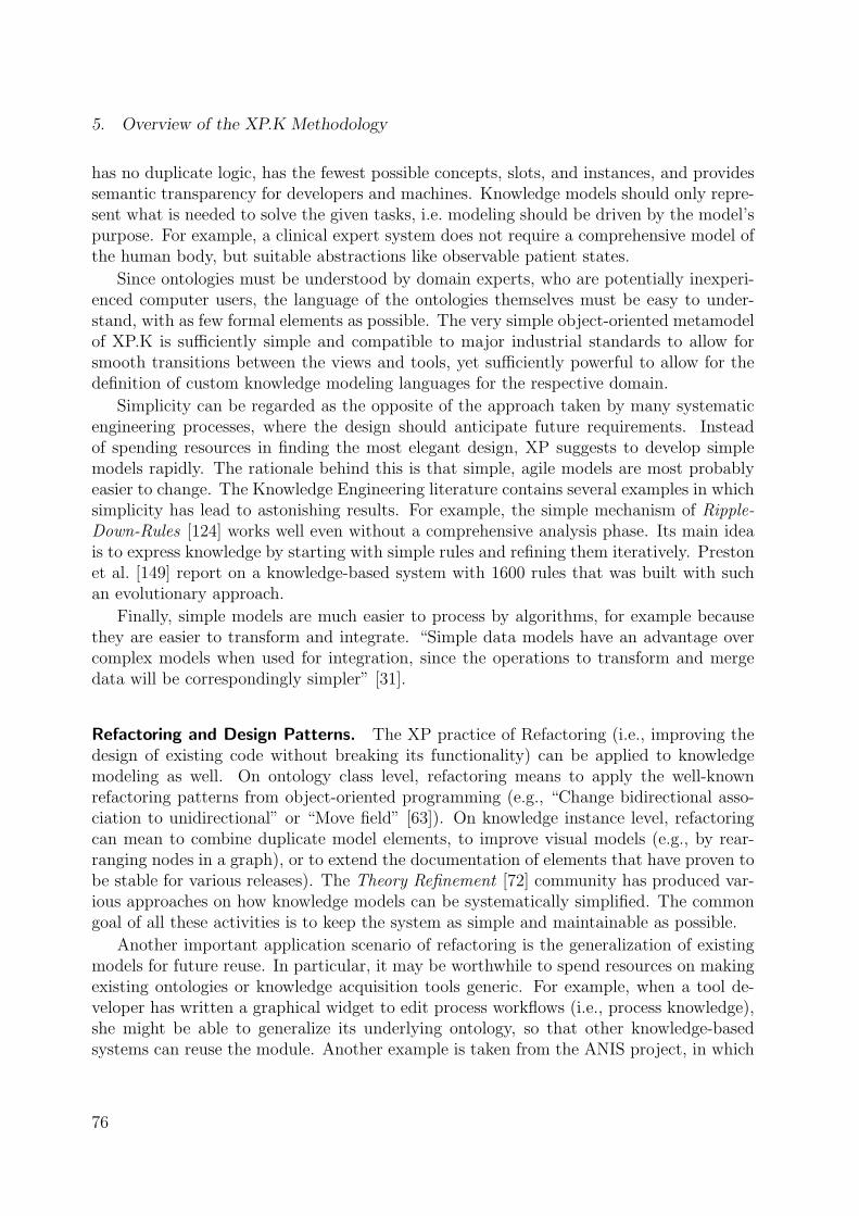
5. Overview of the XP.K Methodology
has no duplicate logic, has the fewest possible concepts, slots, and instances, and providessemantic transparency for developers and machines. Knowledge models should only repre-sent what is needed to solve the given tasks, i.e. modeling should be driven by the model’spurpose. For example, a clinical expert system does not require a comprehensive model ofthe human body, but suitable abstractions like observable patient states.
Since ontologies must be understood by domain experts, who are potentially inexperi-enced computer users, the language of the ontologies themselves must be easy to under-stand, with as few formal elements as possible. The very simple object-oriented metamodelof XP.K is sufficiently simple and compatible to major industrial standards to allow forsmooth transitions between the views and tools, yet sufficiently powerful to allow for thedefinition of custom knowledge modeling languages for the respective domain.
Simplicity can be regarded as the opposite of the approach taken by many systematicengineering processes, where the design should anticipate future requirements. Insteadof spending resources in finding the most elegant design, XP suggests to develop simplemodels rapidly. The rationale behind this is that simple, agile models are most probablyeasier to change. The Knowledge Engineering literature contains several examples in whichsimplicity has lead to astonishing results. For example, the simple mechanism of Ripple-Down-Rules [124] works well even without a comprehensive analysis phase. Its main ideais to express knowledge by starting with simple rules and refining them iteratively. Prestonet al. [149] report on a knowledge-based system with 1600 rules that was built with suchan evolutionary approach.
Finally, simple models are much easier to process by algorithms, for example becausethey are easier to transform and integrate. “Simple data models have an advantage overcomplex models when used for integration, since the operations to transform and mergedata will be correspondingly simpler” [31].
Refactoring and Design Patterns. The XP practice of Refactoring (i.e., improving thedesign of existing code without breaking its functionality) can be applied to knowledgemodeling as well. On ontology class level, refactoring means to apply the well-knownrefactoring patterns from object-oriented programming (e.g., “Change bidirectional asso-ciation to unidirectional” or “Move field” [63]). On knowledge instance level, refactoringcan mean to combine duplicate model elements, to improve visual models (e.g., by rear-ranging nodes in a graph), or to extend the documentation of elements that have proven tobe stable for various releases). The Theory Refinement [72] community has produced var-ious approaches on how knowledge models can be systematically simplified. The commongoal of all these activities is to keep the system as simple and maintainable as possible.
Another important application scenario of refactoring is the generalization of existingmodels for future reuse. In particular, it may be worthwhile to spend resources on makingexisting ontologies or knowledge acquisition tools generic. For example, when a tool de-veloper has written a graphical widget to edit process workflows (i.e., process knowledge),she might be able to generalize its underlying ontology, so that other knowledge-basedsystems can reuse the module. Another example is taken from the ANIS project, in which
76

5.2. Process
I have developed a small rule engine. During and after the project I have generalized theengine’s input ontology, e.g. I removed all hard-coded references to medical concepts likePatientState and replaced them by generic abstract classes such as NumericVariable.These simple refactorings enabled to reuse the same metamodel in different projects (fordetails, see subsection 8.1.4).
A further potential for improving development efficiency lies in the application of object-oriented Design Patterns to knowledge modeling. For example, the Composite pattern [67]is applicable to many situations in which domain concepts form a hierarchy (as shown infigure 8.4 (page 133)). Finding and annotating design decisions with Design Patterns canhelp to improve communication between modelers and support reuse.
Planning Game. The XP practice of the Planning Game suggests that the developmentprocess should be guided by simple “story cards”, which balance business priorities againstthe technically possible. In XP.K, the domain experts stack these story cards according totheir priorities (i.e., the most valuable features first) and the developers attach estimatesabout the required resources. This is repeated until a balance is reached. Thus, expertsand engineers jointly decide on the project’s schedule.
5.2.4. Putting it all Together
The values, principles, and practices described in the previous subsections are the majoringredients of the XP.K methodology and the main things developers should be awareof. XP.K does not prescribe a sequence of modeling activities that should be followed asin systematic engineering methodologies. Approaches such as the ontology developmentmethods from subsection 4.2.1 may be useful during the early stages for the constructionof an initial base model, but once a system is implemented and integrated, XP.K does notspend resources on comprehensive analysis and design activities. Instead, it follows thephilosophy of agile methodologies, in which agility in the face of changing requirementsand knowledge models is a major goal. As illustrated in figure 5.9, XP.K applies varioustechnologies and practices with the explicit goal of reducing the cost of change.
Much of the assumption that the cost of change can be reduced is based on the value ofSimplicity. I argue that simple object-oriented models are easier to change than complexformal models in traditional ontology languages. The models are integrated to prototypesrapidly and frequently, so that expensive misunderstandings can be uncovered and elim-inated early, when the costs of changing them are still low. The principle of TravelingLight, which is implemented by practices such as Round-Trip Engineering of ontologiesreduces code duplication, conversions, and leads to single-paradigm systems that are easierto maintain. Instead of having to update a sequence of models as in systematic engineeringapproaches, XP.K teams mainly need to adjust only a single model. The application ofdesign patterns and refactoring can further contribute to model maintainability and futurereuse. Knowledge-based systems developed this way have a large potential for reuse ofmodels and code, because the high-level views of ontologies can be extracted from thespecific application scenario. Reuse can also take place in the context of tools: XP.K
77

5. Overview of the XP.K Methodology
Cos
t of C
hang
e
Time
RapidFeedback
Object−Orientation
Round−TripEngineering
Simplicity
AutomatedTests
Generic Toolsand Methods
Refactoring,Design Patterns
Pair Modeling
Figure 5.9.: XP.K applies a number of technologies and practices that help to reduce thecost of change.
supports the construction and reuse of generic knowledge acquisition tools. By means ofsemantic transparency, these tools can operate on any ontology and are therefore robustto ontological changes. Pair Programming and Modeling help to detect errors earlier andspreads knowledge. Finally, comprehensive automated tests and simulations help to buildrobust and correct knowledge bases.
A word of caution must be brought forth when stating that Extreme Programmingflattens the traditional cost curve. Cockburn [36] has shown that the exponential costcurve described by Boehm [18] is still in place. For example, an error hidden in a pieceof software that is delivered to customers is far more expensive to fix than if it weredetected prior to delivery day. Clearly, the major impact on costs have changes that aremotivated by late phases (like end-user tests), but that must be fixed in earlier phases(like requirements). Extreme Programming fights this exponential effect by keeping theiterations between requirements and customer feedback extremely short. For example, thepractice of the On-Site Customer makes sure that requirements definition and tests canbe performed very rapidly. The practice of Automated Unit Tests ensures that errors aredetected prior to delivery.
While all these practices have individual weaknesses when applied in isolation, theirmain benefits emerge when used together. The practices of XP.K support each other.For example, a weakness of the Round-Trip Engineering approach for knowledge modelingis that changes to one ontology class can also have an impact on several other modulesbased on the ontology. At the same time, the weakness of writing tests is their additionalcoding overhead. However, when combined, both weaknesses can compensate each other,because test cases make sure that local changes did not damage other modules, and writingtests is much easier when the ontology is part of the test programming environment. Forexample, the most frequently used XP testing tool, JUnit [66], is written in Java as areour ontologies.
Despite being based on the interplay of various practices, XP.K can and should beadjusted to local settings. In particular, the principle of Traveling Light may be softenedto allow for the inclusion of additional modeling artifacts in the process. Medium-sized
78

5.3. Languages
knowledge-based systems will certainly require to fix requirements or important knowledgesources in paper-based documents. Examples include interviews with external domain ex-perts (the so-called knowledge protocols [4]), clinical statistics, informal treatment plans,etc. For example, prior to building a clinical multi-agent system, we produced a compre-hensive model of the clinical processes as they were before we started to modify them.Such artifacts will remain quite stable throughout the process, so that they can be referredto from knowledge models to improve requirements traceability [91].
5.3. Languages
In this section, I will describe a language for the declaration of knowledge models (ontologiesand knowledge base instances). In the context of the metamodel hierarchy introduced infigure 3.7 (page 38), this language represents the M2 Layer. In the following, the languagewill be called XP.KL. I will not rigorously specify the language and its semantics, because(1) the language is very simple, (2) formal specifications are inherently hard to read, and(3) I will provide a detailed Java implementation of it in chapter 6. A formal specificationof XP.KL in the Meta Object Facility (MOF, see subsection 3.3.2) is relatively straight-forward, because XP.KL is essentially a subset of the UML, which is in turn also definedin MOF. Note that XP.K is not bound to XP.KL, but most of its concepts can also beapplied in conjunction with similar languages.
XP.KL is a simple language for the declaration of ontologies and knowledge bases.The main goal of the XP.KL is to integrate smoothly with the values, principles, andpractices of XP.K. In particular, XP.KL supports Simplicity, Community, Rapid Feedback,and Traveling Light. Figure 5.10 shows the classes of the XP.KL in UML/MOF notation.In the following, I will provide details on the diagram elements, by relating them to theKnowledge Engineering language OKBC (see subsection 4.3.1) and the object-orientedlanguages UML and Java.
An XP.KL ontology encompasses the terminology and structure in which knowledgebases are instantiated. An ontology is a collection of classes. A class represents a conceptfrom the domain of interest, comparable to the classes of OKBC, UML, or Java. In termsof the Model-Control-View architecture from figure 3.1 (page 25), classes are purely modelclasses that mainly serve as information containers. Classes have names, which must obeythe usual naming conventions from the object-oriented world (i.e., start with an uppercaseletter, exclude whitespaces, etc.). Classes can be grouped into named packages and areeither abstract or instantiable. Classes can be arranged into hierarchies, but when used inconjunction with Java or C#, only single inheritance is permitted. Instances are objectsas in the Java/UML world. A KnowledgeBase is a collection of instances. The instancesare acquired during knowledge acquisition, and usually remain unchanged throughout theexecution of the knowledge-based system.
The characteristics of instances are defined by the properties of its classes. The termProperty is borrowed from the JavaBeans specification [178], details of which will follow inchapter 6. Using Java, properties are implemented by public getter and setter methods.
79

5. Overview of the XP.K Methodology
Class
name: Stringpackage [0..1]: String
abstract: booleandescription [0..1]: String
subClasses*
1
name: Stringindexed: boolean
description [0..1]: String
PrimitiveProperty
type: PrimitiveType
RefProperty
type
*
*
1
1
Instance
type
Property
Ontology
name: String
superClass
*1
KnowledgeBase
name: String *1
1
*
facetType
*facetOf
Figure 5.10.: The XP.K knowledge modeling metamodel (in UML notation).
Properties fulfill the role of the template slots in OKBC or public attributes in UML.Properties are either simple or indexed. Simple properties store a single value, whereasindexed properties store arrays of values (although the ordering of elements is seldomimportant). Properties are either associations (reference properties) or primitive values.A RefProperty represents a link from one object to another. Links are directed, becausebidirectional links are harder to maintain and reverse-engineer. A PrimitiveProperty cantake values of predefined types (in particular int, double, and boolean) or of classes thatare not ontology classes (e.g., String and Date).
XP.KL requires that the implementation platform (e.g., Java) supports object-orientedreflection [118]. Reflection allows to access metadata about objects, classes, and propertiesat run-time. Using these metadata, programs can find out the attributes of knowledgebase instances and their classes dynamically, so that generic algorithms and tools canbe constructed. Reflection is therefore an essential technique for the implementation ofsemantic transparency. Chapter 6 will provide details on this.
So far, the metamodel is basically an extremely light-weight version of object-orienteddomain models without methods. Thus it should be very easy to learn and apply (even)by domain experts. Since the language can be regarded as the common subset of UMLand Java, support for Round-Trip Engineering is excellent. At the same time, its intendedsimplicity and compatibility with object-oriented standards are limitations, because theyprevent us from adding new language elements such as those from ontology specificationlanguages. In particular, XP.KL copes with its own primitives to represent semantic trans-parency. The powerful concept of facets, which are used in OKBC to express semanticalconstraints on the valid states of domain concepts, can therefore only be supported bymeans of an artifice. The basic idea is to reify properties, so that properties are used todescribe and constrain other properties. These “meta-properties” take the role of facetswithout adding new language elements.
Facet properties are associated to a facetType, which defines a property’s semantics.
80

5.3. Languages
A catalog of pre-defined facet types is introduced in chapter 6. This catalog essentiallycovers the most frequently needed types of constraints (e.g., those from OKBC (table 4.1(page 53)) such as the minimum value, maximum cardinality, and enumerations of admissi-ble values). Ontology authors are however able to add custom facet types. A class accessesits defined facets through the name of the facet type (e.g., maxCardinality). In languagessuch as UML and Java, the link from a property to one of its facets can be implementedimplicitly, by following simple naming conventions (e.g., the property childrenMaxCar-
dinality declares the maximum cardinality of the children property. Reflection can beused to detect and access the declared facets.
Apart from constraints, some ontology languages support the specification of functions,axioms, and rules. Functions specify that the value of a given attribute can (and must)be derived from the values of other attributes. In this view, functions are constraints thatrestrict an attribute’s value to exactly one other value. Axioms are complex restrictionson the valid configurations of several attribute values. Thus, axioms are more expressivethan constraints. Staab and Maedche [171] have shown that the most common types ofaxioms can be generalized to axiom types which can be converted to constraints. Anothermechanism to translate axioms to constraints is to split axioms into multiple constraints,each of which describing the admissible values of the single attributes involved in the axiom.This mechanism, however, can lead to combinatorial explosions, because axioms that putmultiple attributes into relation must be resolved for each of these attributes. Where theseconversions become inefficient or fail, axiomatic expressions can be moved to the objectlevel by defining specific axiom classes which are instantiated or overloaded. Rules can berepresented in various ways by means of objects. For example, as shown by Pachet [143],rules can be implemented through specific object-oriented methods. This approach definesone method for each rule, the parameters of which specify the rule’s premise or left-hand-side and the body of which performs the conditional check and then the rule’s conclusion(which may be to change other attributes). Further axiom and rule declarations could beimplemented by means of the UML Constraint Language OCL [194], although in this caseindividual conventions or tools like OCL compilers need to be introduced to enable theirRound-Trip Engineering with Java. The round-trip approach is summarized in figure 5.11.
The presented language is slightly less expressive than traditional ontology representa-tion languages like OKBC. XP.KL neither supports multiple inheritance, nor the construc-tion of slot hierarchies. Rules and axioms are not explicitly supported, but shifted to theobject level. This, however is not a serious limitation. As already stated in section 4.1,early expert systems failed exactly due to their trying to the capture all knowledge typesby means of uniform logical rules, whereas Knowledge Engineering suggests to expresssuch knowledge in the domain expert’s preferred ontology. For example, the expert canformalize rules in terms of symptoms and diseases instead of writing uniform, formal first-order-logic sentences. Furthermore, graphs of related objects are easier to display visuallythan plain rules. It is questionable whether advanced types of knowledge representationlike axioms are needed in average projects [43], so that the benefits of using traditionalontology languages have to be balanced against their aforementioned weaknesses.
81

5. Overview of the XP.K Methodology
Java/KBeans(Implementation Level)
UML(Design Level)
Ontology(Conceptual Level)
Concepts
SlotsRelationships
Facets(Constraints)
Instances
Classes
Attributes(Relationships)
Facets, [OCL,]Cardinalities, etc.
Instances
Classes
Properties
Facet Properties,Cardinalities
Instances
Figure 5.11.: Round-Trip Engineering of knowledge models between the conceptual domainview, a formal visual UML view, and the system view (here with Java classes).
Although XP.KL is less expressive than specialized knowledge representation languages,industrial practice with object-oriented software has shown that its modeling primitivesare a suitable way of modeling domains. The central task of ontologies, namely to providea formal, explicit specification of concepts and relationships, can be fulfilled with XP.KLquite well. XP.KL supports all of the requirements defined in chapter 2, namely that itis adaptable, easy to learn, translatable, incremental, precise, complete, and – in particu-lar – compatible. Its compatibility allows to export knowledge models into other object-oriented languages or knowledge exchange formats. Ontologies implemented in XP.KLcan be smoothly integrated with other modules, such as reasoning methods, GUIs, andknowledge acquisition tools (as shown in the following section).
5.4. Tools
Each of the roles involved in an XP.K development process should be supported by adequatetools. Developers of system code and knowledge acquisition tools can access the large poolof object-oriented standard development tools such as CASE tools and IDEs. The next twosubsections focus on tool support for the two other developer groups, namely knowledgeengineers and domain experts.
5.4.1. Ontology (Class) Editors
With the simple object-oriented metamodel from the previous section, ontology classes canbe visualized and edited with off-the-shelf UML editors. Probably the most suitable stan-dard tools are modern Round-Trip Engineering tools for UML like Together for Java [184],
82

5.4. Tools
a screenshot of which has already been shown in figure 3.8 (page 40). Such tools are ma-ture, robust, and in the case of Together even free. The visual editing facilities of UMLtools simplify communication with domain experts. However, CASE tools have an over-whelming number of features and opportunities to make mistakes, so that domain expertswill usually not be able to use them on their own. Since XP.K implements the practice ofJoint Ontology Design, it is no problem to let a knowledge engineer perform the changes.
An open issue of using standard CASE tools is how the knowledge bases (instances)can survive schema evolution. Although the UML specification includes Object Diagrams,which are equivalent to our knowledge bases, few tools provide suitable support for them.I will describe tool support for these issues in chapter 7, admitting that handling schemaevolution is expensive. However, these problems are also present in Knowledge Engineeringtools.
5.4.2. Knowledge Base (Instance) Editors
The simplicity and compatibility of the XP.K knowledge metamodel allows to include ahuge amount of editor types into the process. For example, it is easy to define mappingsbetween the ontology classes and relational databases, so that off-the-shelf database toolscan be used and/or extended [22, 191]. Apart from these tools, which are seldom optimizedfor knowledge modeling, the Java incarnation of XP.K comes with a specialized tool calledKBeansShell, which is in detail presented in chapter 7. In order to make the present chapterrelatively self-contained, here is already a brief overview of this tool.
The XP.K knowledge metamodel has explicit support for reflection, i.e. the ability toaccess metadata about the structure of (Java) classes at run-time. I have exploited thisfeature for the development of various generic instance editors, which can operate on anyJava data structure that follow certain coding conventions (the JavaBeans [178] specifica-tion, which implements XP.KL). These instance editors can visualize knowledge bases astrees, tables, forms, graphs, and others. The editors are part of the KBeansShell platformfor the development of knowledge acquisition tools. The shell provides a framework inwhich the generic editors or customized own editing components can be placed. While theontology is relatively unstable, the generic standard editors are used, but when the sys-tem matures, more and more optimized components can be integrated. Figure 5.12 showssome of the editing facilities that the KBeansShell automatically creates for the exampleontology from figure 5.4.
The KBeansShell uses the XP.KL facet mechanism to evaluate constraints, so thatthe domain experts and knowledge engineers are pro-actively notified about inconsistentknowledge bases and get advice on how to repair them. Custom unit testing and simulationfunctions can easily be integrated.
The KBeansShell platform is extremely flexible and open. The customization of theknowledge modeling process by means of user-defined components is probably one of themost rewarding features of the whole Round-Trip approach, because Java-based ontologyclasses can be extended with support code without breaking its semantic transparency.
83

5. Overview of the XP.K Methodology
Figure 5.12.: The KBeansShell, a generic JavaBeans instance editor and knowledge acqui-sition tool.
5.5. Summary
This chapter has provided an overview of XP.K, a pragmatic methodology for the develop-ment of knowledge-based systems. As illustrated in figure 5.13, XP.K combines approachesfrom Software and Knowledge Engineering, so that the weakness of one “world” is coveredby the strength of the other.
XP.K extends the usual object-oriented modeling primitives by approaches that in-crease the model’s semantic transparency. It supports smooth transitions between concep-tual knowledge models and executable code through a simple metamodel that can easily beengineered in a round-trip style. Furthermore, it allows to use various robust and widelyavailable tools for knowledge modeling and supports reuse of generic knowledge acquisitioncomponents. Its compatibility to object-oriented standards makes XK.P a very accessibleand flexible approach, because it allows to access mature and future technologies, compo-nents, frameworks, architectures, and modeling methods.
The overall process of XP.K is very light-weight and agile, so that the developers getfeedback rapidly and frequently, while being able to cope with change efficiently. Insteadof requiring the maintenance of comprehensive documentation artifacts, XP.K relies on
84

5.5. Summary
(OO) Software Engineering Knowledge Engineering
Agile Processes(Extreme Programming)
General−purposelanguages(e.g., Java)
UML
CASE tools
Problem−SolvingMethods and
Inference Engines
Knowledgeacquisitionmethods
Knowledge modeling languages (OKBC)
Round−TripEngineering
IndustrialAcceptance
IDE tools
Design Patterns
Componentlibraries
(Too general, oftenmissing semantics)
(Weak transitionsbetween models)
(Missing KA Tools)
(Little industrialsupport)
Knowledgeacquisition tools
Architectures(MCV)
Knowledgeexchangeformats
Figure 5.13.: Technology and methods from Object-Oriented Software Engineering andKnowledge Engineering are merged in the XP.K methodology.
communication, automated tests, and semantic transparency of the executable code.
The following chapters will provide details on the language (chapter 6) and tools (chap-ter 7) of XP.K, and report on our experience with it from various application scenarios(chapter 8). The limitations and problems of XP.K will be discussed in the final chapter 9.
85


6. KBeans: Implementing XP.K in Java
XP.K is founded on the principle of Traveling Light and practices like Round-Trip En-gineering and Joint Ontology Design. For pragmatic reasons, this means to give up thedependency on specific ontology representation languages, but instead to rely on pureObject-Orientation throughout all project phases. In section 5.3, I have discussed thedifferences between ontology languages and object-oriented programming languages. Myconclusion was that objects are missing declarative semantics which are necessary to en-able ontology sharing, knowledge acquisition, and other reasoning tasks. If we want toemploy objects for knowledge modeling, we need to increase their semantic transparency,so that the “meaning” of the knowledge representing objects and classes is accessible tohumans and machines both at build-time and run-time. A computer’s notion of “meaning”is restricted to values that can be related to other values that have a meaning to humans.Therefore, semantic transparency for machines can be reduced to formal information aboutthe elements of an object model and their relationships. Thus, a key to implementing se-mantically transparent objects is to provide information (or metadata), especially aboutthe valid object states. Constraints like those provided in the ontology language OKBCare a very important type of metadata. Facets (slots that describe other slots) are themodeling primitive for the representation of constraints.
An implementation technique for these metadata must cope with the language con-structs available in the target language. KBeans (Knowledge JavaBeans) [101] is a simpleimplementation technique for semantically transparent class structures in Java. It can beused to implement knowledge models (ontologies and knowledge bases) in pure Java, butis also a valuable programming aid for the development of reusable components in general.KBeans can be regarded as an implementation of the XP.KL language from section 5.3.An earlier version of the approach has been published in [107]. Further information andsupporting software are freely available from the KBeans Homepage [51].
KBeans is an extension of the JavaBeans [178] specification, which defines coding con-ventions and a reflection-based API with supporting classes for the implementation ofreusable components. Some background on JavaBeans and its application of reflection isprovided by the following section 6.1. After that, section 6.2 introduces the basic idea be-hind KBeans. Section 6.3 presents a catalog of predefined KBeans facet types. Section 6.4shows how KBeans can be used in various application domains, in particular for implement-ing ontologies. Section 6.5 describes related approaches to enriching Java with semanticmetadata and discusses benefits and limitations of KBeans. The chapter is summarized insection 6.6.
87

6. KBeans: Implementing XP.K in Java
6.1. Reflection and JavaBeans
The Java Reflection [118] API contains – among others – methods to identify the names andtypes of class attributes and methods. This allows to implement generic algorithms thatoperate on any class structure by dynamically exploring the properties of these classes. Forexample, as illustrated in figure 6.1, it is possible to write an algorithm that dynamicallyinvokes all methods that are available for a given object (here, the MalePerson instance).
a java.lang.Class
name = "MalePerson"abstract = false
a java.lang.reflect.Method
name = "setName"params = [ String.class ]
returnType = void
methods[0]
Adam: MalePerson
name = "Adam"firstNames = ["John"]
age = 42
getClass()invoke()
M1
M0
Figure 6.1.: Object-oriented reflection in Java can be used to access metadata from theclass (M1) level for objects from the instance (M0) level.
The JavaBeans specification [178] defines coding conventions that support the devel-opment of such generic algorithms. The main purpose of the JavaBeans specification is toprovide a uniform interface for reusable classes (precisely, components), that can be ana-lyzed and mutually connected with generic tools, such as visual GUI builders. A JavaBeansinstance (a bean) provides metadata about its features, which are the attributes describingits state, the events it fires, and the methods it offers for other components to call. Theattributes, which are called properties, can be either of a primitive type, references to otherobjects, or arrays of these types (the indexed properties). A JavaBeans class exposes its listof properties by declaring methods that follow pre-defined naming conventions or designpatterns. For example, the following two getter and setter methods declare that the classhas a property called “age” of type int, which can be read and written.
public int getAge() // e.g. { return age; }
public void setAge(int value) // e.g. { age = value; }
Note that reflection can be used to look up which getter and setter methods exist in aJavaBeans class, and to derive the class properties from this information. Properties arecalled bound if they fire a PropertyChangeEvent, whenever their value has changed, i.e. intheir setter method. This follows the Observer design pattern from subsection 3.1.2, insofar
88

6.2. KBeans: Adding Facets to JavaBeans
that objects that wish to be notified about changes can register themselves as observers (orlisteners in the Java terminology) of the target bean or one of its properties. Thus, beansdo not only provide static metadata, but can also pro-actively notify their environmentabout changes.
JavaBeans is particularly suitable for the development of data structures that can beedited with generic instance editing tools, because it provides explicit support for cus-tomizing the visual appearance of objects and properties by so-called Customizer andPropertyEditor objects. Figure 6.2 shows the use of JavaBeans components in a visualGUI builder. Here, the component class JButton specifies a foreground property andprovides a PropertyEditor that displays a combobox in which the button’s foregroundcolor can be selected conveniently.
Figure 6.2.: The use of JavaBeans components in a visual GUI editor (here, Forte forJava [180]). The properties of the form elements selected in the left windowcan be inspected and edited in the customizer on the right.
This attractive metadata support makes JavaBeans a candidate implementation plat-form for semantically rich data structures that can be processed by generic classes andtools. However, the types of metadata provided by the JavaBeans standard are quite lim-ited. There is little information provided apart from the names, types and access rights ofthe properties. In the following sections I will show that other useful metadata – especiallyconstraints – can (and should) be supplied by Java classes, by implementing facets withdesign patterns very similar to those from JavaBeans.
6.2. KBeans: Adding Facets to JavaBeans
This section presents the KBeans approach to define and evaluate facets that declaremetadata about JavaBeans properties. An example based on figure 5.4 (page 66) will helpto convey the main idea. In order to declare the constraints that the (inclusive) minimum
89

6. KBeans: Implementing XP.K in Java
age of a person is 0 and that a person’s spouse may not be one of his or her children, weadd the following members to the Person class.
public final static int ageMinInclusive = 0;
public Person[] getSpouseInvalidValues() { return children; }
As illustrated in figure 6.3, these fields and methods can be detected and evaluated bya reflection-based facet engine.
<< JavaBeans class >>
Person: Class
children: Propertytype = Person[ ]
dup licateFree: FacetfacetValue = true
has−property
declared−facets
maxCardinali ty: Facet
getFacetValue () : int
KBeansFacet Engine
− Facet detection− Facet evaluation− Constraint checking− Constraint violation repair A
pplic
ati
ons
Uses reflection toaccess metadata
Providesmetadata for
Developer declaresmetadata with facets
Figure 6.3.: The main idea of KBeans is to attach facets to JavaBeans properties, whichcan be accessed by means of reflection.
The following semi-formal definitions will lay an ontological foundation for the rest ofthis section. Here, property is a property of a given JavaBean bean that is decorated witha facet.
facet: (bean × property × facet type) → facet value
facet value: A primitive Java value, an Object, or null.
facet type: facet name → type mapping
facet name: A Java identifier which is unique among the facet types that areinstalled in the Java Virtual Machine.
property type: The Class of property.
type mapping: property type → facet value type
facet value type: The Class of the facet value or null.
constraint type: A facet type with a validation method.
validation method: (value × facet value) → boolean
In other words, a facet declares one Java value for a given property of a given bean. Ifthis value is null, then the facet is treated as not declared. The class and semantics of thefacet value are defined by the facet type. Each facet type has a unique name and a type
90

6.2. KBeans: Adding Facets to JavaBeans
mapping function, that derives the type of the facet value, given the type of the property.The result of the type mapping can be null to indicate that the facet type cannot beapplied to the given property type. A constraint type is a facet type with a validationmethod which can check whether a given value would be a valid property value, given thebean’s current facet value.
In order to add facets to a given JavaBeans class, KBeans supports two types of facetdeclarations:
• Dynamic facet declarations are methods that match the signature defined in subsec-tion 6.2.1. These methods compute facet values dynamically, i.e. they may returndifferent results for every bean with every method invokation.
• Static facet declarations are fields that match the signature defined in subsection 6.2.2.These fields store a constant facet value for all beans of the class.
6.2.1. Dynamic Facet Declarations
Let’s assume we wish to declare a facet of the facet type with the name facetName for aproperty called propertyName of the Class C. The facet is declared dynamically, if C hasa method of the following signature
public <facetValueType> get<PropertyName><FacetName>()
where facetValueType is the result of the facet’s type mapping for the given propertytype, and both propertyName and facetName are capitalized in conformity with the Java-Beans naming rules. The method’s prefix can be is instead of get, if the facetValueTypeis boolean. The current facet value is defined by the result of the method call. In theexample from the beginning of this section, the property name is spouse, the facet nameis invalidValues and the facet value type is Person[], because the type of spouse isPerson. The facet value is the array of the values of the children attribute.
Since the method signature above is compatible to the naming conventions of Java-Beans getter methods [178], the facets themselves can be accessed and formally defined asJavaBeans properties:
Definition (Dynamic Facet Declaration). A dynamic facet declaration fora property is a readable JavaBeans property with the facet’s value type andthe name propertyName + capitalize(facetName).
The fact that facets for a property are themselves properties has several consequences.We can read and (if a setter method is supplied) write the facet values just like otherproperty values. This includes that we can use existing bean-based tools and methodssuch as GUI builders and persistence mechanisms to modify them. Furthermore, we canrecursively define meta facets that constrain other facet values.
91

6. KBeans: Implementing XP.K in Java
Another interesting issue with facets declared as methods is inheritance. Approachessuch as Design-by-Contract [125] define that class invariants must be inherited from su-perclasses, so that subclasses can only make the invariant more restrictive. In the caseof constraining KBeans facets, this means that a method overloading an inherited facetmethod must return a value at least as restrictive as the result of the super methods. If wefunneled all facet access through specific utility classes (such as the FacetIntrospector
described in subsection 6.2.4), we could implement a mechanism that automatically invokesthe super methods and delivers a list of facet values for a given facet type. However, inconformity with the usual semantics of inheritance in Java, where programmers can freelymodify an object’s behavior by overloading, it appears to be better to put the responsibilityfor overloading facets into the hands of the programmer. In those cases where overloadingis strictly not permitted, developers can declare the facet declaring methods as final.
It is important to note that facet methods – similar to getter methods in general – mustbe free of side-effects. In particular, they must not modify any variable beyond their localscope. The reason for this is that the facet methods can not make any assumptions aboutwhen they are invoked.
The extreme flexibility of dynamic facet declarations, which is due to their potentialto perform arbitrary computations within their method bodies, is at the same time ablessing and a curse. Facet access is expensive, because the methods have to be calledeach time a facet is being evaluated, and for every object individually. The methods donot provide any information about whether their return value has changed since the lastcall. Furthermore – and in many cases most importantly – their facet value is the resultof a “black box” procedure that reduces its semantic transparency. It is impossible toreason or make any assumptions about the facet value itself at run-time. This also makesit barely possible to export the semantics to other formats such as XML Schema andOKBC. Covering the case that such a stronger notion of semantic transparency is needed,the following subsection introduces the concept of static facet declarations.
6.2.2. Static Facet Declarations
Let’s (again) assume we wish to declare a facet of the facet type with the name facetNamefor a property called propertyName of the Class C. The facet is declared statically, if Chas a field of the following signature
public final static <facetValueType> <propertyName><FacetName>
A rather executable definition follows.
Definition (Static Facet Declaration). Let field be the result of the call ofgetField(propertyName + capitalize(facetName)) for the Class thatowns a property. field is a static facet declaration for the property, if it ispublic, final, and static and has the facet’s value type.
92

6.2. KBeans: Adding Facets to JavaBeans
The (constant) value of this field is regarded as the facet value for all instances ofthe class. Similar to their dynamic counterparts, static constraint declarations that are“overloaded” by a namesake field in a subclass should ensure that the overloaded valuesare more restrictive than the values of the super fields.
6.2.3. Coding Conventions
Beside having a meaning in KBeans, both dynamic and static facet declarations can also betreated as normal fields and methods. Thus, the distinction between “normal” fields andmethods and those that declare facets is rather blurred. However, semantic transparencyrequires that other developers and programs are supplied with clear, unambiguous facetdeclarations. Otherwise, programmers might not recognize existing facet declarations orproduce incorrect declarations by accident due to misspelling methods. A solution tothese problems could be to extend the Java specification by a new modifier keyword (e.g.,facet) that would make the declaration of facets explicit. Since such an extension willnot be available in the near future, we need to cope with an intermediate compromise.Most of the problems described above can be reduced by an automated facet declarationchecker, which uses reflection to detect apparent facet declarations that are misspelled orhave illegal value types.
Apart from this tool, the following coding conventions can make facet declarationsmore readable and reduce oversights. The facet names should convey their semanticsand make their role as a facet declaration clear. For example, the purpose of a methodcalled getLastNameMaxLength is clearly accessible to readers of both source code andcorresponding UML diagrams. Since all facet declarations contain a concatenation ofproperty and facet names, they are easy to relate to their role. In order to make facetseven more apparent, the names of the facet types could include predefined keywords, e.g.end with FACET.
On source code level, it is common practice to conglomerate methods that cover similaraspects. In order to enable programmers to quickly browse a JavaBeans property and itsfacets, I recommend to place getter and setter methods and the facet declarations aboveeach other. The facet values should be precisely described with a commentary block, sothat the semantics are transparent to developers from the automatically generated JavaDocAPI documentations alone. Using the predefined @see tag of JavaDoc, properties shouldprovide cross-references to the facets that are defined on them, as shown in the methoddefinition from figure 6.4. This also allows to automatically detect oversights, becauseJavaDoc will report misspelled facet declarations.
A technical weakness of the KBeans approach is that programmers could choose toadd both static and dynamic facet declarations to the same class. Like facet overloading,such situations will normally occur infrequently, but they are technically possible. Ourcompromise here is to define that if both types are detected for a class, then the dynamicdeclaration has priority over the static one.
93

6. KBeans: Implementing XP.K in Java
/**
* Sets the values of the children property.
* @param values the new children
* @see #getChildrenMaxCardinality
* @see #isChildrenDuplicateFree
* @see #isChildrenOrdered
*/
public void setChildren(Person[] values) { ... }
Figure 6.4.: JavaDoc comments can be used to document constraint declarations.
6.2.4. Accessing and Processing Facets
Figure 6.5 displays a UML diagram of Java classes that can be used to access and processfacets efficiently. An implementation of this facet engine is available from the KBeansHomepage [51].
Facet types are defined by means of classes that implement the FacetType interface.Each FacetType has methods that can be used to check whether a facet declaration ofthe given type is admissible for a given property type and to compute the type map-ping. If a facet type class also implements the ConstraintType interface, it must define amethod to check whether a given value would satisfy the semantics behind the constraint.For example, I have defined a class MaxCardinalityConstraintType, which implementsConstraintType and which can check whether a given indexed property does not have agreater cardinality (array length) than the facet value. This class furthermore implementsthe RepairableConstraintType interface to provide a “repair” method that derives a validvalue from an invalid one, by removing those array positions that exceed the maximumcardinality. The source code of the MaxCardinalityConstraintType class can be foundin Appendix C.
The FacetType classes must be centrally registered in the FacetTypeRegistry, whichmaintains a list of facet types so that reflection-based classes can find out what to lookfor. KBeans supports a number of core facet types (see section 6.3), which are installedby default. However, applications are free to add individual new facet types, preferablyin static initializer blocks that are automatically executed when the JavaBeans class thatuses the facet type is accessed for the first time.
The main functionality of the facet engine is accessible through the FacetIntro-
spector. This static utility class uses reflection to detect the fields and methods thatmatch the patterns of the installed static and dynamic facet types. The FacetIntro-
spector associates the JavaBeans PropertyDescriptors with FacetDescriptors, whichhave links to the respective facet fields and methods and thus store the result of the reflec-tion process for future access.
94

6.3. A Catalog of KBeans Facets
<< Interface >>FacetType
getName (): StringgetFacetType (type:Class): ClassisAdmissibleType (type:Class): booleantoString (facetValue:Object): String
<< Singleton >>FacetTypeRegistry
install (facetTypeClass:Class)
*installedFacetTypes
<< Singleton >>FacetIntrospector
<< Interface >>FacetDescriptor
getFacetValue (bean:Object): Object
*
DynamicFacetDescriptor
getter
StaticFacetDescriptor
facetValue:Object
beanClass
facetType
property
(has properties)*
java.lang.Class
java.beans.PropertyDescriptor
java.lang.reflect.Method
java.lang.reflect.Field
(stores value of)
<< Interface >>RepairableConstraintType
getValidValue (bean, property, facetValue, value): Object
methodsfields
**
{ public final static }
The FacetIntrospector usesreflection to detect the Fields or Methods that match the patterns of the installedFacetTypes. These patternsare stored in FacetDescriptors.
<< implements >> (gets value from)
<< Interface >>ConstraintType
isValidValue (bean, property, facetValue, value): boolean
Figure 6.5.: The core classes of the KBeans facet engine.
6.3. A Catalog of KBeans Facets
This section presents the catalog of the standard facet types installed in the FacetType-
Registry of KBeans. The goal of this catalog is to cover the most frequently needed typesof metadata to support semantic transparency, while remaining as small and simple aspossible. The most frequently needed facet types have been derived from the ontology ex-change standard OKBC (table 4.1 (page 53)) and from XML Schema [200], an XML-basedspecification language for describing the syntax and semantics of a class of XML docu-ments. Being an official standard recommendation of the World Wide Web Consortium,XML Schema is rapidly gaining acceptance as a standard for document exchange on theinternet. Details on the facet types of XML Schema can be found in Appendix D.
Since XML Schema and OKBC have similar goals, because they both stem from do-mains that deal with communicating data and knowledge bases between distributed sys-tems, I decided to include all of their standard constraint types into KBeans, apart froma few exceptions which do not make sense in the context of Java. The inclusion of thesestandards allows to use the KBeans approach to smoothly integrate semantically rich data
95

6. KBeans: Implementing XP.K in Java
structures from other languages into Java programs. In this context, data binding [154]involves compiling (XML) schemas or ontologies into Java classes, which handle the trans-lation between external documents and objects. Existing data binding frameworks forXML Schema (e.g., Enhydra Zeus [48] and Castor [28]) generate Java source code – inparticular, JavaBeans classes. The static facet declarations from KBeans can be used toimprove data binding and even Round-Trip Engineering of ontologies [103], XML Schemafiles and JavaBeans classes.
The KBeans constraint types furthermore embrace some elements of UML class dia-grams [21], such as cardinalities and inverse relationships. These elements are seldom statedexplicitly in Java code, so that reverse engineering from Java to UML is complicated.
A summary of the KBeans facet catalog is shown in table 6.1. A detailed specificationof the single facet types can be found in Appendix A. The references to Java types in thetable and the rest of this document are as follows.
<type>: any type
<simple>: any non-indexed type
type[]: the indexed variant of type
<primitive>: any primitive type, or String
<object>: any non-primitive type, except String
<numeric>: {byte, double, float, int, long, short}, or the respective wrapper types(Integer, etc.)
<comparable>: a <numeric>, or a class implementing java.lang.Comparable
The facet names follow the usual naming conventions of Java, so that some XMLSchema and OKBC constraint types have been renamed. The three XML Schema facetsnot implemented as KBeans standards are whitespace (which is only relevant for XMLparsing), totalDigits (which can be expressed in terms of maxLength and maxExclu-
sive), and length (which is the conjunction of minLength and maxLength). Similarly, theOKBC facet :CARDINALITY is not implemented in KBeans, since it is simply an abbrevia-tion of :MIN-CARDINALITY and :MAX-CARDINALITY. Note that it is possible to dynamicallyadd these facet types to KBeans, by adding appropriate FacetType classes to the Facet-
Registry from figure 6.5.
6.4. Application Scenarios
KBeans has been successfully applied in several development projects [108, 105, 160], inparticular from the domains of knowledge-based systems and multi-agent systems. Al-though its initial intention was to support the implementation of ontologies in Java, it
96

6.4. Application Scenarios
Table 6.1.: The standard facet types of KBeans.
Facet OKBC XML Schema Property FacetType equivalent equivalent types value type
defaultValue - - <type> <type>
maxLength - maxLength/totalDigits <type> int (≥0)
minLength - minLength <type> int (≥0)
fractionDigits - fractionDigits float�, double� int (≥0)
maxCardinality :MAXIMUM-CARDINALITY maxLength/maxOccurs <simple>[] int (≥0)
minCardinality :MINIMUM-CARDINALITY minLength/minOccurs <simple>[] int (≥0)
validClasses :VALUE-TYPE - <object>� Class[]
invalidClasses - - <object>� Class[]
maxInclusive :NUMERIC-MAXIMUM maxInclusive <comparable>� <comparable>
minInclusive :NUMERIC-MINIMUM minInclusive <comparable>� <comparable>
maxExclusive - maxExclusive <comparable>� <comparable>
minExclusive - minExclusive <comparable>� <comparable>
validValues :SOME-VALUES enumeration <type> <simple>[]
requiredValues - - <simple>[] <simple>[]
invalidValues - - <type> <simple>[]
notNull - - <type> boolean
inverseProperty :INVERSE - <object>� String
equalProperty :SAME-VALUES - <type> String[]
unequalProperty :NOT-SAME-VALUES - <type> String[]
validValuesProperty :SUBSET-OF-VALUES - <type> String[]
requiredValuesProperty - - <type>[] String[]
invalidValuesProperty - - <type> String[]
pattern - pattern <type> String
ordered - - <comparable>[] boolean
duplicateFree :COLLECTION-TYPE - <type>[] boolean
validValuesNames - - <type> String[]
�Facet type is applicable to both simple and indexed type.
has shown to be very useful in other domains as well. With the metadata provided byKBeans classes, machines and humans are able to prevent, detect, and eventually repairobject states that violate the semantics intended by their developers. This section willdemonstrate how KBeans technology can be used for these purposes.
6.4.1. Implementation of Semantically Rich Domain Models
Any non-trivial software system will contain a model of the problem domain. For ex-ample, a database system might comprise the domain model about persons and familyrelationships from figure 5.4 (page 66). According to the Model-View-Control architec-ture (figure 3.1 (page 25)), such domain models should be implemented by non-visualmodel classes. The container classes typically employed for this in Java are structured likeJavaBeans classes, i.e. with little apart from getter and setter methods for each attribute.However, the model’s underlying assumption, which are frequently added as constraintsor comments to UML class diagrams, are typically not implemented transparently. Theseassumptions are important, because they constrain the space of valid application scenar-ios, and thus allow to use and reuse models safely and efficiently. However, when domainmodels are implemented in Java, their original semantics are usually obscured behind
97

6. KBeans: Implementing XP.K in Java
non-transparent programming primitives. The constraint that a person’s age must not benegative might be implemented by if-clauses that reject negative values before they areassigned to the age attribute (e.g., in the setAge method). The constraint that a person’smarital status must be one of three predefined constants might be implemented by threeappropriate radio buttons. Thus, the semantics are typically implemented implicitly, es-pecially by making sure that any execution path through the program will result in validobject states. The complexity of potential execution paths often leads to systems that areerror-prone, hard to understand and maintain, and almost impossible to reverse engineer.A KBeans implementation of domain models, such as the Person class (which can be foundin Appendix B), makes the model’s semantics explicit.
6.4.2. Ontology Implementation
KBeans can be used for the implementation of frame-based OKBC ontologies by mappingontology concepts to JavaBeans classes, slots to properties, and OKBC facets to (static)KBeans facets. However, KBeans is less expressive than OKBC. In particular, KBeansdoes not support the following:
• Multiple inheritance is not directly supported, because concepts are implemented byJava classes. Java (and C#) classes have exactly one superclass. A certain degree ofmultiple inheritance can be achieved by representing concepts with Java interfaces(abstract classes without method bodies), because each Java class can implement anynumber of interfaces. Interfaces can even contain static fields, so that static facetdeclarations are possible.
• Slots are not treated as first-class instances, i.e. slots can neither be put into aninheritance hierarchy, nor enriched by slots themselves. Both aspects can be easilysimulated by declaring intermediate concepts that represent slots. Note that it ispossible to attach facets to slots, and – by means of dynamic facet declarations –facets to facets.
Compared to purely declarative ontology languages, KBeans ontologies and domainmodels have a much greater flexibility because of the imperative features (methods) anda huge amount of available code libraries that can be directly attached to the semanticobjects. For instance, it is possible to add reasoning code of Problem-Solving Methodsdirectly to the method’s input and output ontologies. Fensel et al. [56] describe an approachfor implementing Problem-Solvers, which are specified in the formal language UPML, inJava (cf. subsection 4.3.2). Similar to our own previous work [103], they even propose tomap ontologies to an ordinary class hierarchy (in a JavaBeans style). KBeans facets canbe used to specify the semantics of these classes. Furthermore, KBeans can be used tointegrate interface code to clinical devices and other data sources much more naturallythan if ontology classes from external files were used. It is also possible to implement sideeffects of method calls (e.g., to update private attributes that depend on other attributes),to compute values like facets dynamically, etc. Despite this mix of implementation details
98

6.4. Application Scenarios
and structural ontological information, the semantic transparency of the ontologies is notobscured. In particular, it is possible to re-extract an ontology from KBeans classes, insupport of model reuse.
The major advantage of implementing ontologies with KBeans is compatibility to ex-isting object-oriented standards, especially when the rest of the application is written inJava as well. This allows to implement smooth transitions between the various modelingartifacts. Developers can travel light in the sense of Extreme Programming, i.e. they cankeep all structural information about the ontologies in Java classes. This allows to imple-ment the interactions between ontologies and other modules very smoothly. Programmerscan use the language they are used to and have all information in one and the same model,increasing development speed and reducing code duplication. Furthermore, many powerfultools and auxiliary classes can be used for ontology development. All of the currently mostwidely used visual Java development tools have explicit support for JavaBeans, so thatproperties can be added, visualized, and edited conveniently without writing source code.Other generic classes for JavaBeans exist, such as various JavaBeans-to-Database mappingtools (e.g., [179]) and XML-based persistence mechanisms like the JavaBeans Archiverpackage [182].
6.4.3. Ontology Sharing and Mapping
The persistence mechanisms described above are a central building block for the implemen-tation of ontology sharing and mapping between systems and components. As illustratedin figure 6.6, KBeans ontologies can be translated from a source model (e.g., a domainmodel) to a target model (e.g., a Problem-Solving Method’s input ontology). First, theJavaBeans objects from the source structure are serialized to the JavaBeans XML for-mat [182] by means of the java.beans.XMLEncoder class. Then, the XML stream istranslated with a declaration of mapping rules in the XML schema translation languageXSL [199]. Finally, the resulting XML stream is transformed into JavaBeans objects withthe java.beans.XMLDecoder class.
KBeans ontologies can also be used in multi-agent systems. Here, an agreement on thesemantics and constraints on the possible values of the ontological concepts is necessary toenable inter-agent communication. An agent receiving invalid messages can either rejectthem or try to use metadata to “repair” them. I have implemented an efficient messagingapproach based on the standard agent platform FIPA-OS [60]. Here, agents share ontologiesby using common KBeans classes. The single (distributed) agents can have individualimplementations of these classes, i.e. they can add own methods or attributes, but agreeon common constraints. (This can be implemented by pushing all the property access andfacet code into abstract superclasses that can be overloaded with local classes.) Agentscommunicate by exchanging (FIPA) messages which contain JavaBeans objects that areconverted to XML streams. On message receipt, the agents are able to validate the beanswith the KBeans constraints. I will return to this issue in section 8.2.
99
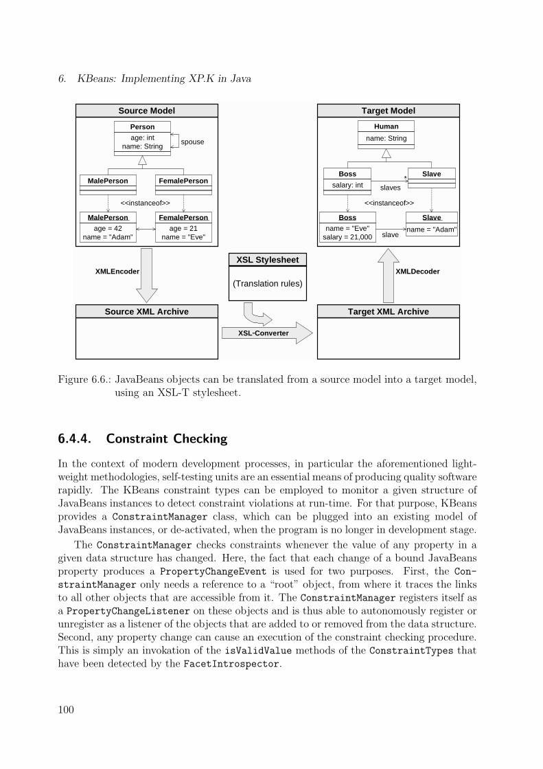
6. KBeans: Implementing XP.K in Java
Source Model
XMLEncoder XMLDecoder
Target Model
Person
age: intname: String
FemalePersonMalePerson
MalePerson
age = 42name = "Adam"
FemalePerson
age = 21name = "Eve"
<<instanceof>>
spouse
Human
name: String
SlaveBoss
salary: int slaves
Boss
name = "Eve"salary = 21,000
Slave
name = "Adam"
<<instanceof>>
slave
*
Source XML Archive Target XML Archive
XSL Stylesheet
(Translation rules)
XSL−Converter
Figure 6.6.: JavaBeans objects can be translated from a source model into a target model,using an XSL-T stylesheet.
6.4.4. Constraint Checking
In the context of modern development processes, in particular the aforementioned light-weight methodologies, self-testing units are an essential means of producing quality softwarerapidly. The KBeans constraint types can be employed to monitor a given structure ofJavaBeans instances to detect constraint violations at run-time. For that purpose, KBeansprovides a ConstraintManager class, which can be plugged into an existing model ofJavaBeans instances, or de-activated, when the program is no longer in development stage.
The ConstraintManager checks constraints whenever the value of any property in agiven data structure has changed. Here, the fact that each change of a bound JavaBeansproperty produces a PropertyChangeEvent is used for two purposes. First, the Con-
straintManager only needs a reference to a “root” object, from where it traces the linksto all other objects that are accessible from it. The ConstraintManager registers itself asa PropertyChangeListener on these objects and is thus able to autonomously register orunregister as a listener of the objects that are added to or removed from the data structure.Second, any property change can cause an execution of the constraint checking procedure.This is simply an invokation of the isValidValue methods of the ConstraintTypes thathave been detected by the FacetIntrospector.
100

6.4. Application Scenarios
In the context of knowledge-based systems, the constraint checking mechanism is par-ticularly useful during knowledge acquisition, to test the correctness of knowledge models.Details on this will be elaborated in chapter 7.
The ConstraintManager is quite efficient for the evaluation of static constraints, be-cause only those constraints that directly concern the property that has changed need tobe checked. However, it can become quite inefficient for dynamic constraints, because themethod bodies of dynamic constraint declarations can contain hidden dependencies, sothat on each change of a property, all dynamic constraints need to be evaluated. Thisinefficiency will usually not slow down knowledge acquisition, where property changes aremade one-by-one and manually through a user interface.
6.4.5. Semantic Annotation of Reusable Components
The basic idea of component-based development is to build applications by plugging to-gether reusable building blocks (components), which encapsulate their state and exposetheir services through well-defined interfaces. However, the presence of externally devel-oped components within a system introduces new challenges for software engineering activ-ities, particularly due to hidden dependencies among components, reduced testability, anddifficulties in program understanding [141]. The main reason for these problems is the lackof information about components that are not internally developed [141]. Frequently, de-velopers have implemented semantical assumptions that are neither transparent to otherdevelopers nor to the software environment in which the components are embedded in.As a result, object-oriented classes (including components) are frequently instantiated inways that violate these assumptions. KBeans facets can be used to specify the intendedsemantics and admissible application scenarios to humans and machines.
Graphical widgets such as Java’s Swing classes are a very popular type of components.As already shown in figure 6.2, comfortable off-the-shelf visual modeling tools allow tocombine simple widgets like buttons and text fields to dialogs and other complex com-ponents. Their visual appearance and behavior can be easily modified by changing thecomponents’ properties. Visual modeling tools analyze the components’ interface, detectthe properties and their types, and provide respective editors generically. For example, theJButton class from the Swing library has a verticalTextPosition property, which speci-fies whether the button’s text shall be aligned to the left, the right, or the center. However,although the verticalTextPosition property is of type int, only three values are validfor it (namely the predefined constants LEFT, RIGHT, and CENTER). Without metadata inthe style of KBeans, generic editors are unable to reject invalid values which counteractthe component builder’s intended semantics. Adding facets like defaultValue, validVal-ues, and validValuesNames to the verticalTextPosition property would significantlyimprove semantic transparency.
The metadata provided by KBeans facets can be employed by generic user interfacecomponents. These components could have labels or “tool-tip” texts that describe theexpected values (e.g., “Amount (10..100):”), or change their background color if the userenters an invalid value. If a finite number of values is defined by a validValues facet, then
101

6. KBeans: Implementing XP.K in Java
a combo box or a group of radio-buttons can be used. If a maxLength facet is present, thena text field can automatically constrain the number of characters. All these componentsreduce development overhead, because programmers only need to explicate the objectmodel’s semantics, and the corresponding input dialogs or forms can be developed rapidlyby visually plugging together generic components. The user interface code could even begenerated automatically.
Driving the idea of generic components further, I have developed a tool called KBeans-
Shell that serves as a graphical editor and knowledge acquisition tool of any structure ofJavaBeans instances. Details on this tool will be supplied by chapter 7.
6.5. Discussion
6.5.1. Related Work
Other approaches for the implementation of semantic transparency for Java classes exist.One approach (e.g., [121]) is to include external formats such as XML Schema or OKBCdocuments into the software architecture and rely on the facet services provided by parsersand components for those languages. However, such a mixture of Java and external filescomplicates software maintenance and contradicts to the paradigm of Traveling Light.Furthermore, it requires an infrastructure to access the objects from the external files asJava objects. Access to data from XML or ontology documents is traditionally implementedby translating them into an intermediate layer of objects, such as DOM trees. This is veryflexible, as it allows to access documents the schemas of which are unknown at build-time. However, it complicates access to the data contained in the documents and meansan artificial mixture of modeling levels, because entities that are naturally considered asclasses are treated as instances.
The lack of an efficient constraint mechanism in Java has been a widely discussed issuefor years. The huge demand for an appropriate Java extension has lead to the addition of anew assert keyword in Java 1.4 [181]. Here, an assertion is understood to be a statementcontaining a boolean expression that the programmer believes to be true at the time thestatement is executed. assert statements are useful to check constraint satisfaction at run-time, especially pre- and post-conditions in the sense of Design-by-Contract. The followingcode snippet shows how assertions – here in conjunction with KBeans constraints – can beused to check a pre-condition to prevent illegal value assignments.
public void setAge(int value) {
assert FacetIntrospector.isValidValue(this, "age", value);
this.age = value;
}
A major limitation of the assert statement is that it does not make explicit what typeof contract it supports, e.g. there is no way to declare that a given boolean expression
102

6.5. Discussion
represents a post-condition. This problem is tackled by other approaches, such as iCon-tract [49]. iContract uses a precompiler that converts code from predefined commentaryblocks into executable Java code, as in the following example:
/**
* @pre value >= 0
*/
public void setAge(int value) { ... }
This approach can increase the semantic transparency of classes and methods to hu-mans, because the expressions from the commentary blocks will also appear in the APIdocumentation. However, the need for an additional translation step and tools is a con-siderable overhead.
A different approach is taken by jContractor [95], where class invariants, and pre- andpost-conditions can be specified by means of specific methods that match predefined designpatterns very similar to the KBeans approach. For example, the following method declaresthe pre-condition of the setAge method.
protected boolean setAge_PreCondition(int value) {
return value >= 0;
}
Calls to these boolean methods are inserted into the byte code by means of special classloaders and object factories.
All of these approaches are limited to constraint checking, i.e. they only evaluate booleanexpressions, but do not provide any additional metadata about what they constrain. Theonly way to get more information about the constraints – and thus to increase semantictransparency for machines – would be to parse and analyze the source or byte code, whichis in general far too complex to be feasible. Facet-based approaches such as KBeans canprovide much more metadata, because they are declarative instead of imperative.
Instead of defining facets in special fields and methods like in KBeans, other approachesrely on run-time objects to represent facets. Okunev’s [139] draft of a validation approachfor JavaBeans properties makes use of the fact that the PropertyDescriptors, whichare the result of the JavaBeans reflection process, can be decorated with arbitrary dataitems (using the setValue method). Thus, metadata can be associated with predefinedconstraint types (e.g., "maxLength"). This approach is quite complicating to use, becausethe authors of constraints need to define additional BeanInfo classes, which are hard toread and (reverse) engineer. A similar approach is presented by McLaughlin [121], whoemploys XML Schema files and data binding to express and read model semantics intoJava objects. The constraints are translated into one Constraint object for each XMLSchema type. The Constraint class has methods such as getMinInclusive that returnthe facet values defined in the schema. This approach, however, relies on external schemafiles, and is thus only an option if the object models are specified in XML Schema. Bothapproaches are also limited to static facet declarations, whereas dynamic KBeans facetscan evaluate anything that can be expressed in Java.
103

6. KBeans: Implementing XP.K in Java
6.5.2. Benefits and Limitations of KBeans
KBeans is a highly pragmatic, simple, and natural extension of JavaBeans. Its simplicitylies in the use of clear design patterns that are easy to apply, comprehend, and evaluate.The fields and methods implementing the patterns are based on pure Java code and do notrely on external formats or declarations. Particularly, the metadata that provide semantictransparency remain with the class they describe, so that component exchange is facilitated.The constraint methods do not have any negative impact on system performance, becausethey only provide optional metadata.
KBeans is fully compatible to the Java specification, i.e. no changes to the compilerare necessary to use it. Only a small library of core classes is required to implement facetaccess (e.g., the facet engine from subsection 6.2.4). Since each of the facet declarations isoptional, and their omission in a class means to apply Java defaults, any existing JavaBeansdata structure is backwards compatible to KBeans. Furthermore, KBeans can be flexiblyextended by custom facet types. The space of potential application scenarios of facetmetadata is vast.
Applying KBeans technology in projects only requires a minor adaptation of the pro-gramming style. Whereas programmers would usually implement the semantics of theirmodels implicitly, they need to get used to making constraints and other metadata explicit.This is not necessarily an overhead, because all of the relevant metadata that can be ex-plicated in facets are usually implemented somewhere in the code anyway. For example,the names and valid values of the maritalStatus property from figure 5.4 are typicallyimplemented in the corresponding GUI elements. Thus, enriching components and sharedobject models by facets is mostly a question of reorganizing the classes. In general, devel-opers who increase semantic transparency by explicitly embedding the intended semanticsof their classes into design and implementation artifacts (i.e., UML diagrams and Javacode) integrate the goal of component reuse early in the development process (cf. [11]).
KBeans can be supported by tools both at run-time and during development. At run-time, reflection can be used to support visual builders and other generic programming andknowledge acquisition tools. During development and modeling, KBeans facets appearjust like other class members, i.e. they can be visualized in UML diagrams, edited withoff-the-shelf IDEs, and they can even be engineered in a round-trip style. By the way,the concepts of KBeans are not limited to Java, but can be transferred to other reflectivelanguages such as C#.
The major limitation of KBeans, when faced with the problem of semantic transparencyin general, is its applicability to JavaBeans only. JavaBeans must fulfill various attributes,in particular, they must be public, and have a list of public properties. This limitation doesnot concern ontologies and reusable components, the goal of which is to declare explicit,sharable class structures, that are public by their very nature.
As stated above, any approach to adding semantic transparency to object models isnecessarily a compromise between what is available and what is desirable in Java. Aweakness of KBeans is that the distinction between facet declarations and other fields andmethods is relatively weak. I have proposed tool support and coding conventions which
104

6.6. Summary
help to resolve this problem. Another issue is the great proliferation of class members,which can make classes hard to read, understand, and change. A pragmatic approach toreduce the complexity of the resulting UML diagrams is to filter all public, final, staticfields. However, my opinion is that facet declarations should be considered as an integralpart of any JavaBeans class, just like (other) public method declarations.
6.6. Summary
This chapter has introduced a simple and natural extension of the JavaBeans standardcalled KBeans. The main purpose of KBeans is to support the development of semanti-cally transparent domain models (ontologies) and components. KBeans achieves this bysupporting the declaration and evaluation of facets, which provide metadata about thevalid values of JavaBeans properties. As illustrated in figure 6.7, KBeans achieves build-time transparency by defining coding conventions that allow source code parsers to extractontology declarations from ordinary Java classes, and thus enable Round-Trip Engineeringbetween UML and Java ontologies. Source parsers need to look up methods and fields thatmatch the signatures that are predefined by the coding conventions. The KBeans codingconventions are also used to increase an object’s semantic transparency at run-time. Here,Java’s reflection capabilities can be employed to find out which fields or attributes andmethods are defined for an instance.
Build−Time Run −Time
Round −Trip EngineeringRapid prototyping
Joint ontology designOntology exchange
Requirements tracing
Ontology mappingOntology sharing
Constraint checki ngGuiding user inpu t
Generic too ls and PSMs
Source Code Parsing Reflection / Introspection
KBeans Coding Conventions
Semantic Transparency with Metadata
Figure 6.7.: JavaBeans and KBeans technology can be used to increase the semantic trans-parency of Java classes both at build-time and run-time.
Facets can be used to prevent, detect, and repair invalid object states. KBeans sup-
105

6. KBeans: Implementing XP.K in Java
ports a catalog of facet types, which embraces related standards such as XML Schema andOKBC. From the criteria defined for modeling languages in chapter 2, KBeans thereforescores exceptionally high in compatibility and translatability. KBeans is also adequateand easy to learn, because it relies on Object-Orientation which is equally simple as pow-erful. The paradigms of encapsulation and the local scope of object definitions supportsincremental knowledge acquisition. KBeans is also precise and complete, because Java isa general-purpose language.
I have demonstrated the benefits of KBeans in case studies from the domains of com-ponent reuse, ontology sharing, and software testing. The following chapter will introducea generic knowledge acquisition tool based on KBeans.
106

7. KBeansShell: A Generic Frameworkfor Knowledge Modeling Tools
After the language aspects from the previous chapter, I will now elaborate on the tool di-mension of the XP.K methodology. While XP.K and KBeans rely on standard UML toolsfor ontology editing, specific tool support for the construction of knowledge bases (in-stances) is required. The Software Engineering world does not focus on instance modelingand although Object Diagrams are an official part of UML, they are barely supported bythe current generation of tools. Knowledge Engineering tools like those mentioned in chap-ter 4 can be employed in conjunction with an Extreme Programming approach, but sufferfrom relying on specific knowledge acquisition languages which lead to the aforementionedintegration problems.
This chapter introduces KBeansShell, a Java-based library of generic components thatcan be efficiently assembled to build customized knowledge acquisition tools (shells). In itsvery basic form, KBeansShell provides a graphical user interface with which domain expertscan edit instances of KBeans classes (ontologies) as trees, forms, tables, and graphs. Theshell also provides generic services like constraint checking, file management, undo, andclipboard operations. These generic base services and reusable GUI components reduce de-velopment costs for tools and thus support rapid evolution of knowledge models in the faceof feedback. KBeansShell is therefore particularly geared for agile development processesof knowledge-based systems. Its tight integration of Java-based ontologies enables smoothtransitions between the knowledge models and the underlying software infrastructure.
This chapter does not only introduce tool users and developers to the features of theKBeansShell implementation, but also supplies developers with information on which fea-tures are commonly found in knowledge acquisition tools and how they can be built inobject-oriented languages. Section 7.1 provides an overview of the general architecture ofKBeansShell and its implementation as a Java framework. Section 7.2 describes the singlereusable components from the module library. Section 7.3 provides practical guidelineshow KBeansShell can be used efficiently. Section 7.4 shows how KBeansShell can be usedto edit not only instances, but also KBeans classes. The chapter is summarized in sec-tion 7.5. The application of KBeansShell will be illustrated throughout the sections andalso elaborated in chapter 8 in the context of larger case studies. Note that the values,principles, and practices of XP.K do not depend on this specific implementation.
107
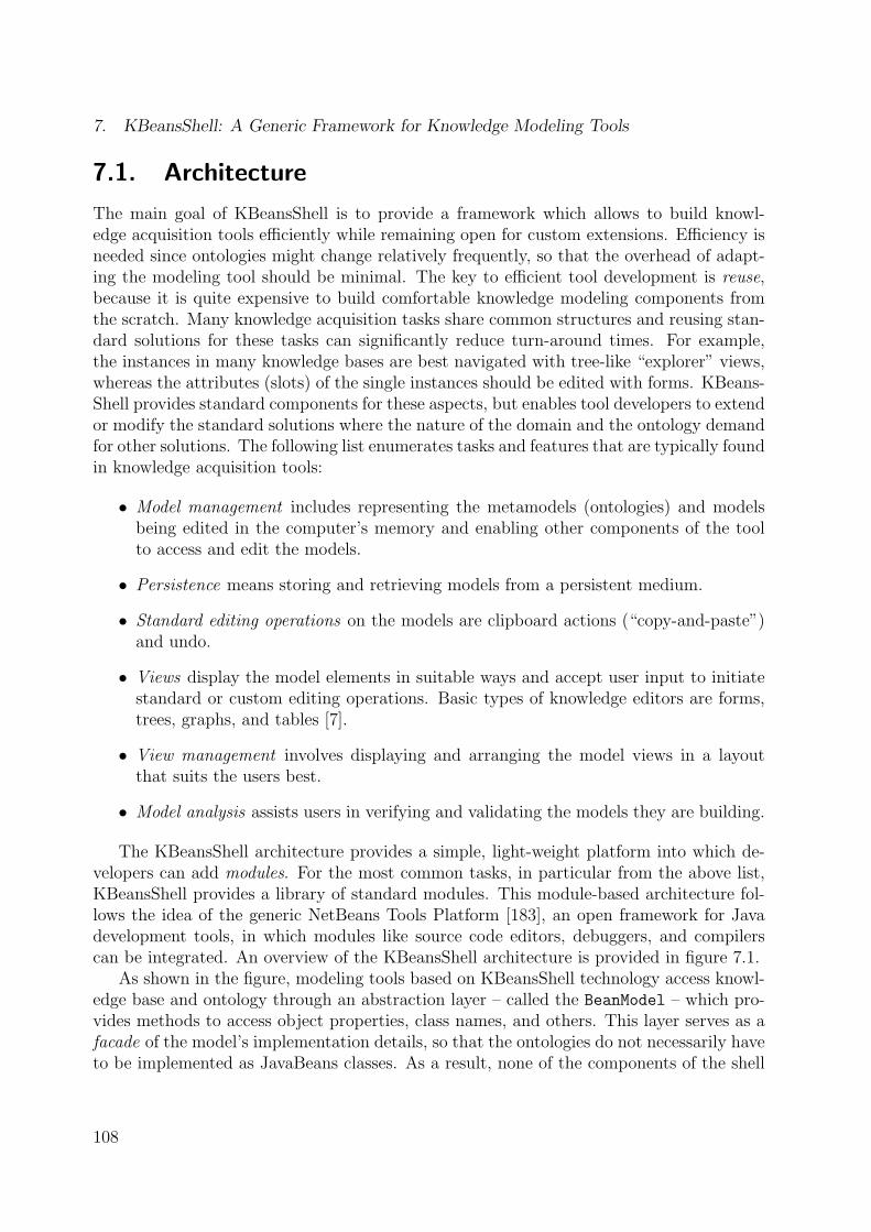
7. KBeansShell: A Generic Framework for Knowledge Modeling Tools
7.1. Architecture
The main goal of KBeansShell is to provide a framework which allows to build knowl-edge acquisition tools efficiently while remaining open for custom extensions. Efficiency isneeded since ontologies might change relatively frequently, so that the overhead of adapt-ing the modeling tool should be minimal. The key to efficient tool development is reuse,because it is quite expensive to build comfortable knowledge modeling components fromthe scratch. Many knowledge acquisition tasks share common structures and reusing stan-dard solutions for these tasks can significantly reduce turn-around times. For example,the instances in many knowledge bases are best navigated with tree-like “explorer” views,whereas the attributes (slots) of the single instances should be edited with forms. KBeans-Shell provides standard components for these aspects, but enables tool developers to extendor modify the standard solutions where the nature of the domain and the ontology demandfor other solutions. The following list enumerates tasks and features that are typically foundin knowledge acquisition tools:
• Model management includes representing the metamodels (ontologies) and modelsbeing edited in the computer’s memory and enabling other components of the toolto access and edit the models.
• Persistence means storing and retrieving models from a persistent medium.
• Standard editing operations on the models are clipboard actions (“copy-and-paste”)and undo.
• Views display the model elements in suitable ways and accept user input to initiatestandard or custom editing operations. Basic types of knowledge editors are forms,trees, graphs, and tables [7].
• View management involves displaying and arranging the model views in a layoutthat suits the users best.
• Model analysis assists users in verifying and validating the models they are building.
The KBeansShell architecture provides a simple, light-weight platform into which de-velopers can add modules. For the most common tasks, in particular from the above list,KBeansShell provides a library of standard modules. This module-based architecture fol-lows the idea of the generic NetBeans Tools Platform [183], an open framework for Javadevelopment tools, in which modules like source code editors, debuggers, and compilerscan be integrated. An overview of the KBeansShell architecture is provided in figure 7.1.
As shown in the figure, modeling tools based on KBeansShell technology access knowl-edge base and ontology through an abstraction layer – called the BeanModel – which pro-vides methods to access object properties, class names, and others. This layer serves as afacade of the model’s implementation details, so that the ontologies do not necessarily haveto be implemented as JavaBeans classes. As a result, none of the components of the shell
108

7.1. Architecture
Shell (Basic Platform)
Frame Clipboard Undo Layout
Ontology(Classes,
Properties,Constraints)
Bea
nM
odel
(Abs
trac
tion
Laye
r)
Model(Beans)
Installed Modu les
ExtendedGraphConstraint−Checker
Modu le Library
Persistence
Tree
Graph
Customizer
Constraint−Checker
Table
HierarchyPersistence MyHierarchy
Customizer
Customized Modeling Too l
MyModule
Figure 7.1.: Customizing a knowledge modeling tool by reusing and extending generic mod-ules.
can (or should) make assumptions about the “physical” implementation of the model. Inthe most common usage scenarios, the shell would implement the model by means of localKBeans objects, but the objects from the model might also originate from an Active ObjectModel [61] or reside on a remote database with classes defined in an XML schema. TheBeanModel encapsulates the implementation of the model and can be completely replacedon demand. The BeanModel’s interface methods are listed in Appendix E.
Beside the BeanModel, the modeling tool consists of a basic shell. Think of the shellas a graphical application or frame which contains all other modeling views and managesall types of user interaction with the model. As shown in figure 7.2, the default shell is atop-level window with a menu bar, a tool bar, a desktop area and a status bar.
(A marginal note: In the implementation of the KBeansShell, the Shell is a Javainterface – an abstract class that defines the signatures of the methods that need to beimplemented by any shell. Thus, other classes or graphical components than those shownin the figure could implement the Shell’s services.)
The Shell provides generic clipboard and undo operations on model elements. Addi-tionally, it is the container of model views, which – in the default implementation – areinternal windows that can be opened and freely arranged on the shell’s main desktop area.Arranging these views is supported by the shell’s “intelligent” layout services.
This basic core platform can be extended by installing modules. Modules are Java-based components that are either developed from the scratch, reused as-is from a libraryof generic modules, or reused and extended from the library by means of object-orientedinheritance.
A rather formal overview of the Java classes and interfaces of KBeansShell is providedin figure 7.3. The central interfaces are Shell, BeanModel, Module, and View. Each Shell
109

7. KBeansShell: A Generic Framework for Knowledge Modeling Tools
Toolbar with custom andstandard Actions (file,
clipboard, undo, layout)
Statusbar formessage display
Desktop area containingthe various views withcustomizable layout
Menubar with standardand custom Actions
Figure 7.2.: An empty default shell, with only the file persistence module installed.
has exactly one BeanModel, which provides access to the ontology and the current model.Views are subclasses of java.awt.Component, i.e. visual GUI elements, that can appear
in a Shell. Views typically allow to display or edit the properties of the beans in the model.BeanViews are Views that allow to select a bean. Among others, this allows the Shell
to implement generic clipboard mechanisms, which require a certain object to be selected.Figure 5.12 (page 84) shows a sample KBeansShell with various views, such as trees andgraphs. Each Shell can have several installed Modules. Modules can be of one of thefollowing types.
• ViewModules provide information about a type of Views. This includes a method tocreate a new instance of the View and a method that defines whether there are morethan one instance of the given View type allowed in a single shell. Other methodscan specify an icon that can – for example – be used in buttons on the shell’s toolbar. BeanViews are specialized Views that can define a selected object or property.
• ActionModules provide information about an action. Actions are typically accessiblefrom menus or tool bar buttons. When an ActionModule is installed, the shell maygenerate appropriate menu items or buttons. BeanActionModules are specializedActionModules that allow to add actions to specific object types only. The actionsthat are available for a given object can then be selected by opening a simple pop-upmenu in a tree or other Views.
• PersistenceModules implement a persistence mechanism for model files. Modelfiles may be written in an XML-based format or any other format like OKBC. APersistenceModule must specify a file suffix (e.g., "*.xml") and methods that ac-tually load or save a model. The shell automatically provides appropriate “Open”and “Save” actions to access the installed persistence formats.
110

7.1. Architecture
<<interface>>
Shell
addView (view:View)createBean (): ObjectcreateBean (beanView:BeanView): ObjectdisplayMessage (status:String, msg:String)removeView (view:View)selectFileName () : StringtoFront (view:View)
The descriptor of apluggable Shell module
<<interface>>
Module
getName () : Stringinit (shell:Shell)
<<interface>>
PersistenceModu le
getFileSuffix () : StringgetFileTypeName () : StringloadRootBeans (beanModel, fileName) : Object[]saveBeanModel (beanModel, fileName)
<<interface>>
ViewModu le
createView () : ViewgetIcon () : IconisSingleton () : boolean
<<interface>>
ActionModu le
getAction () : ActiongetGroup () : StringgetMenu () : StringonToolBar () : boolean
A Module describinga type of Views
<<interface>>
View
getTitle () : String
<<interface>>
BeanView
getSelectedBean () : ObjectgetSelectedProperty () : ObjectgetSelectedPropertyOwner () : ObjectselectBean (bean:Object)selectPropertyValue (bean,property,index)
installedModules *
(creates)
<<interface>>
BeanModel
...
Undo Manager
...
fileName : String
*
EditManager
...
Access to the beans(instances) being edited
Clipboard management(copy & paste of beans)
Undo and redomechanism A View that allows to
select a bean or aproperty value
A visual componentto display or editbeans and properties
A Module providinginformation about amenu or toolbarAction in the Shell
A Module implementing apersistence mechanism forbeans (load & save format)
Figure 7.3.: A schematic view of some of the core classes of the KBeansShell library.
KBeansShell provides a collection of services, which are described in the following.
Clipboard Operations
Users of modern graphical user interfaces expect to find clipboard actions. KBeansShellprovides generic implementations of these services and places global copy-and-paste buttonsinto the window’s toolbar. The shell basically monitors which view has the focus, gets theobjects selected by the user, and asks the view to handle the chosen actions. The genericimplementations use reflection to access the selected bean’s properties. For example, if theuser hits the “delete” button while a certain property is selected, it passes null to theproperty’s setter method in the selected object.
Undo Mechanism
KBeansShell provides an automated undo mechanism, with which users are able to undothe previous actions and redo them later. These actions are accessible by respective but-tons in the shell’s toolbar. The implementation of these services makes use of the factthat each change in a KBeans model fires a PropertyChangeEvent which encapsulates allinformation needed to undo an editing step. The event objects particularly store old andnew values of the property that has changed. The shell’s undo service records all the Prop-ertyChangeEvents up to a predefined maximum. Visual GUI elements that allow users to
111

7. KBeansShell: A Generic Framework for Knowledge Modeling Tools
edit instances thus do not have to worry about implementing their own undo stack. Theyare, however, able to optimize the generic service by bundling events that logically belongtogether, so that complex changes can be undone with only a single undo button click.
View Management and Layout
Another global service of the KBeansShell is view management. Users are freely able toopen, move, resize, and close the available views of the knowledge model. For each ofthe installed ViewModules, the shell generates corresponding toolbar buttons and menuentries. While this provides much of the flexibility needed during knowledge acquisition,users may typically work with only a selection of the views and arrange them in recurringlayout patterns. For that purpose, each KBeansShell has a ShellLayouter object andone or more ShellLayout instances. Each ShellLayout supplies the ShellLayouter withinformation on how the available views should be arranged. All of this information onlycontains recommendations and relative preferences, which the layouter has to adjust to theactual screen size and number of views. For that purpose, the ShellLayouter splits thescreen into five regions (NORTH, EAST, SOUTH, WEST, and CENTER) which can be addressedby the ShellLayouts. Each ShellLayout provides the following information:
• A list of default views which shall be automatically opened when the system starts,and when the user hits the “reset layout” buttons.
• The relative size of each region.
• For each type of view a region, a relative size within the region, and a priority whichindicates which view shall occupy the center area, if the area is vacant.
• A fill mode for each region, which indicates whether the views shall be arrangedhorizontally, vertically, or stacked (cascaded) within a region.
• A name and an icon, so that the Shell can create appropriate menu entries andtoolbar buttons (e.g., “Activate graph browsing layout”).
7.2. Standard Modules
Modules are reusable building blocks of KBeansShell-based tools. This section will intro-duce the standard modules of the (current) KBeansShell distribution. Each of the modulesis introduced with a brief informal description, application scenarios and a sceenshot (ifthe module is a ViewModule).
7.2.1. Persistence Modules
The task of persistence modules is to enable users to open and save knowledge bases inspecific file formats.
112

7.2. Standard Modules
File Persistence
The FilePersistenceModule allows to save object models to the KBeans file format, aproprietary language that produces simple, but comprehensible text files. There is anextension of the FilePersistenceModule, called LayoutFilePersistenceModule, whichstores additional *.layout files, which specify the layout of the nodes in a BeanGraph (seesubsection 7.2.2).
XML Persistence
The XMLPersistenceModule exports object models to the XML-based Java Archiver For-mat, the JavaBeans persistence mechanism introduced with the Java 2 platform, Version 1.4in 2001. This format ensures tool inter-operability, since the leading vendors of Java de-velopment tools have committed to it. Furthermore, the XML-based files can be processedfurther, for example by translating them to other XML languages with the XML transfor-mation language XSL-T.
7.2.2. View Modules
View modules manage a certain type of GUI elements (views), which can be placed ontothe shell’s desktop area. Table 7.1 provides an overview of the standard view modules fromthe KBeansShell library.
Table 7.1.: An overview of the standard View modules of KBeansShell. The last twocolumns indicate whether the view can visualize primitive properties or rela-tionships between the instances, respectively.
View name is BeanView Primitive Properties RelationshipsBeanTree yes no yesHierarchy yes no (one property only)BeanTable yes (of selected class only) noTree/Table yes (of selected class only) yesBeanGraph yes no yesCustomizer no yes (optional)
Constraint Violations no no no
These view classes are completely generic, i.e. they can be used in conjunction with anyKBeans ontology. The views make heavy use of object-oriented reflection, which enablesthem to detect which classes and properties are available and to generate appropriate edi-tors for the current instances. The views furthermore follow the observer pattern, i.e. theyregister themselves as PropertyChangeListener on the instances and update automati-cally when changes on the model objects occur. This strict separation of model and view
113

7. KBeansShell: A Generic Framework for Knowledge Modeling Tools
allows to use multiple of the views in parallel without having to hard-code dependenciesbetween them.
BeanTree
The BeanTree (figure 7.4) is a hierarchical view that displays objects and their relation-ships. The objects are represented as tree nodes. A node has one child node for each ofthe object’s reference properties. If the property is indexed, the child node is labeled afterthe property and has the property values as children. Otherwise, the child node shows theproperty name and the object being referred to (or a dash, if the reference is null).
Figure 7.4.: The BeanTree view displays objects as tree nodes and their reference propertiesas child nodes.
Above the tree, three buttons represent standard actions for the selected tree node.The “New object” button allows to insert a new node (i.e., object) at the selected position.The other two buttons allow to change the ordering of values within a reference property.
The BeanTree is a very suitable view for object models that are rather hierarchical.It allows to browse and select objects quickly and is best used in conjunction with aCustomizer (see below), which allows to edit the properties of the selected object. Thetree is easy to learn and standard clipboard operations can be intuitively applied to it.
The main weakness of the tree – if used alone – is that it is impossible to add referencesbetween existing objects with it. Although it would be technically feasible to implement a“select and assign” functionality to solve this problem, other editing options such as graphsor the tree/table combination from below are much more intuitive. Furthermore the treemight confuse users as it allows to display identical objects more than once and to browseinto an infinite depth.
The appearance of BeanTrees in a shell can be customized. First, the icons appearingbeside each of the tree nodes can be modified. For that purpose, the BeanTree analyzesthe BeanInfo supplied by the object’s JavaBeans class and checks whether a custom icon
114

7.2. Standard Modules
is supplied. Second, the BeanTree can be subclassed, so that, for example, new buttonscan be added to its toolbar or specific root nodes can be defined.
Hierarchy
The Hierarchy (figure 7.5) is a BeanView that displays a tree of objects of a single class.The child node relationship in this tree reflects the values of one explicitly specified referenceproperty. For example, a Hierarchy can display the children property between Person
objects. In this case, the tree will only contain the child objects, and – in contrast to theBeanTree – ignore any other relationship between Persons like spouse.
The fact that a Hierarchy operates on a specified property of a given class means thatit is necessary to parameterize it. Thus, there is no ready-to-use Hiearchy Module, but anabstract template implementation of Module for which the class and property parametersneed to be overloaded by subclasses.
Figure 7.5.: The Hierarchy displays a specified reference property by means of tree ofobjects. Here, the subClasses property of Java classes is shown.
BeanTable
The BeanTableView (figure 7.6) displays the objects from a knowledge base in a table withone row for each object. A combo-box can be used to select the types of objects that shallappear in the table. If no type has been selected (default), then the table contains only twocolumns, which display the objects’ classes and names. If a certain type has been selected,additional columns show the property values. The objects in the table can be sorted bycolumns.
The table is well suited to get a complete overview of the objects in the model and toidentify which objects exist. However, it is complicating to trace references between theobjects, so that the table is incomplete for object editing.
115

7. KBeansShell: A Generic Framework for Knowledge Modeling Tools
Figure 7.6.: The BeanTableView displays all objects in the model in a “flat” table.
The BeanTableView is also used in a module called BeanSelectionDialog (figure 7.7),which prompts the user to select an object from the current knowledge base. This is acommon task in user interfaces. Using the BeanSelectionDialog is very simple, as shownin the following code snippet, which displays the dialog from figure 7.7) and assigns thechosen object to the variable o.
Object o = new NewBeanSelectionDialog(
"Select a Medium or create a new one",
getShell(),
Medium.class
).go();
Tree/Table
The TreeTableView (figure 7.8) meets the recurring demand for a component in whichobjects can be linked to each other, for example when a spouse shall be assigned to agiven Person. TreeTableViews allow to browse the existing objects in a BeanTree whileshowing the potential valid values for the selected node in an associated BeanTable. Thetable can be filtered to display only those values that do not violate any of the constraintsdefined for the chosen node.
BeanGraph
Graphs are a popular means of visualizing entities and their relationships. The Bean-
GraphView (figure 7.9) is a view that allows to display and edit instances as nodes andtheir relationships as edges. BeanGraphViews provide commands to display a compactoverview of the graph, to search for specific nodes, to zoom in and out, and to arrange thenodes by means of various layout algorithms.
116

7.2. Standard Modules
Figure 7.7.: The BeanSelectionDialog is a simple dialog that allows to select one objectfrom the current knowledge base, or – optionally – to create a new instance ofa given class.
The default implementation of the graph visualizes all instances from the knowledgebase by uniform rectangles. This is useful for general overviews and browsing, but thegraphs frequently become unintelligible. Therefore, the BeanGraphView has an compre-hensive adaptation interface. First, the graph classes can be adapted by subclassing them.The graph package that has been developed as a byproduct of the KBeansShell is very mod-ular and has been used in various other projects at the FAW as well (e.g., POWM [158]).Second, ontology classes can supply metadata about how they wish to be displayed. TheBeanGraphView uses reflection to check whether a BeanNodeComponent class is defined fora given ontology class, which defines the component that shall represent an instance of theclass. For example, the “female” images in the graph from figure 5.12 (page 84) have beenimplemented by defining a FemalePersonNodeComponent class. Third, the BeanGraphViewcan be customized by means of a complex mapping mechanism, in which tool developerscan specify whether instances and relationships shall be displayed as nodes, edges, or notat all. Among others, this allows to visualize and edit objects which represent relationships(association classes) as edges and to mask instances of specific types.
Customizer
Whereas the aforementioned view types focus on the instances and their relationships, theCustomizerView allows to edit the values of primitive properties. As shown in figure 7.10,CustomizerViews are forms which contain editing components for each property of a givenobject. The object to be edited in the CustomizerView must be selected in one of the otherBeanViews (e.g., a BeanTreeView). The type of editing components depends on the typeof the associated property, i.e. textfields for String properties and checkboxes for booleanproperties. The default editors exploit the KBeans constraint mechanism by restricting
117

7. KBeansShell: A Generic Framework for Knowledge Modeling Tools
Figure 7.8.: The TreeTableView allows to edit the relationships between the model objectsin a tree while displaying the potential valid values for the selected node in anassociated table.
user input, for example to display a combo-box when only a finite number of values has beendeclared to be valid (see the maritalStatus combo-box in the right part of figure 7.10).CustomizerViews make use of JavaBeans’s built-in support for PropertyEditor classes,so that individual editors can be defined for properties without having to modify theCustomizerView class.
Beside primitive properties, CustomizerViews can also be used to edit non-primitiverelationships. For that purpose, users only need to activate the “plus” button in the upperleft corner and appropriate lists or selection panels will appear. As shown in the right partof figure 7.10, referenced objects are recursively displayed by embedded customizers.
The default appearance of the CustomizerView can be completely replaced with customcomponents. KBeansShell automatically uses java.beans.Customizer classes, if theyhave been declared for a given JavaBeans class. These Customizers are Java componentsthat have the full control over how an object’s properties are presented to the user.
Constraint Violations
Users of KBeansShell-based tools can open a ConstraintViolationsView during knowl-edge acquisition. As shown in figure 7.11, this view lists the currently violated constraints,i.e. invalid property values. Constraint violations are checked after each modification inthe knowledge base, so that the list is always up to date. For each violation, the object andproperty are displayed, together with a descriptive text and a repair hint that instructsusers about potentially valid values. A double-click on a constraint violation selects theinvalid property in one of the active views, e.g. a BeanTree or Customizer. Thus, errorscan be fixed quickly. The view also provides buttons that allow to assign the proposedrepair values directly.
Technically, the ConstraintViolationsView is based on the ConstraintManager class(subsection 6.4.4). It uses the toString method of the ConstraintType class (subsec-
118

7.2. Standard Modules
Figure 7.9.: The BeanGraphView is a highly configurable display of objects and their rela-tionships. This figure shows a graph that is using the default settings.
tion 6.2.4) to generate descriptions of the constraint violation, and the getValidValue
method of the RepairableConstraintType class to generate potentially valid values.
Other Potential Standard Views
In addition to the standard views described above, other types of generic componentscan be implemented. Frequently, custom components that have proven to be useful in agiven project, can be generalized by replacing the references to specific ontology classes toreflection-based generic classes. For example, the BeanTree component was developed byexploiting the underlying design pattern of hierarchical relationships.
Other generic components can be developed to make reasoning modules accessible dur-ing knowledge acquisition. For example, a generic query module can be developed inwhich users are able to request all objects that match pre-defined search criteria. Fur-thermore, a view to access rule-based reasoning engines like the Java Expert System Shell(JESS, http://herzberg.ca.sandia.gov/jess) would be useful. Also, access to genericProblem-Solving Methods can be implemented, for which only a mapping from domainontology to method ontology needs to be defined. Theoretically, any Java library or com-ponent can be installed as a Module in the KBeansShell, so that the overhead of integratingexternal classes is very small.
119
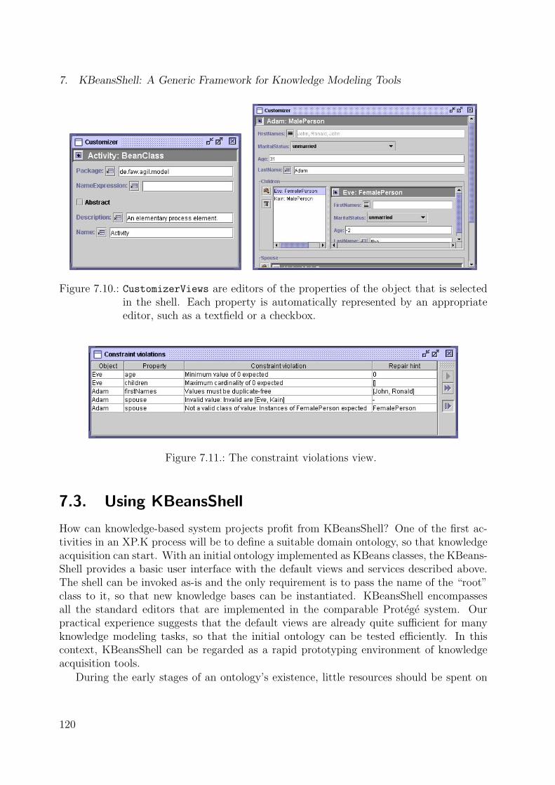
7. KBeansShell: A Generic Framework for Knowledge Modeling Tools
Figure 7.10.: CustomizerViews are editors of the properties of the object that is selectedin the shell. Each property is automatically represented by an appropriateeditor, such as a textfield or a checkbox.
Figure 7.11.: The constraint violations view.
7.3. Using KBeansShell
How can knowledge-based system projects profit from KBeansShell? One of the first ac-tivities in an XP.K process will be to define a suitable domain ontology, so that knowledgeacquisition can start. With an initial ontology implemented as KBeans classes, the KBeans-Shell provides a basic user interface with the default views and services described above.The shell can be invoked as-is and the only requirement is to pass the name of the “root”class to it, so that new knowledge bases can be instantiated. KBeansShell encompassesall the standard editors that are implemented in the comparable Protege system. Ourpractical experience suggests that the default views are already quite sufficient for manyknowledge modeling tasks, so that the initial ontology can be tested efficiently. In thiscontext, KBeansShell can be regarded as a rapid prototyping environment of knowledgeacquisition tools.
During the early stages of an ontology’s existence, little resources should be spent on
120

7.4. The MetaKBeansShell
custom modeling components like specific graphical editors, because the ontology mightbe relatively unstable. The reuse of generic standard components allows to quickly adaptto ontology changes. Successively, tool builders might want to replace the generic com-ponents with customized solutions. Light-weight changes can be made by implementingPropertyEditors, Customizers, or NodeComponents for specific properties and classes,without having to modify or overload the KBeansShell base classes. Greater changes canbe made by adding custom views to the shell by installing appropriate ViewModules.
The KBeansShell supports testing through its built-in constraint checking module. Italso allows to integrate customized ActionModules which can be used to execute auto-mated tests and simulations at any time. Some examples for this will be provided inchapter 8.
7.4. The MetaKBeansShell
The aforementioned use of KBeansShell technology was focused on the acquisition of in-stances (knowledge bases). However, it can be applied to edit classes (ontologies) as well. Ihave implemented an extension of KBeansShell in which the objects are themselves classes,i.e. instances of a meta-ontology. This extension, the MetaKBeansShell is shown in fig-ure 7.12.
The basic idea behind this tool is that classes of the metamodel level can be recursivelyrepresented as first-level instances from the model level as well. The MetaKBeansShelloperates on a KBeans ontology that implements a set of classes similar to the metamodelfrom figure 5.10 (page 80), including classes like PrimitiveProperty and Facet. TheMetaKBeansShell contains a CustomizerView to edit class and property details, displaysthe inheritance of classes in a HierarchyView (figure 7.5), and allows to edit classes ina UML-style diagram. The latter diagram is an application of the BeanGraphView, inwhich objects representing classes are mapped to graph nodes, and objects representingnon-primitive properties to edges.
The major benefit of the MetaKBeansShell is its ability to generate Java source code.The classes of the meta-ontology have code generation methods and the MetaKBeansShelloffers ActionModules which allow to start code generation for all or selected ontologyclasses. However, this code generation will overwrite any existing previous version of theclass and thus also overwrite individual changes made by system developers or knowledgeengineers. The tool therefore also supports incremental source generation and reverseengineering of existing Java classes. This Round-Trip Engineering makes use of the openIDE provided by the NetBeans/Forte Tool platform [183]. As illustrated in figure 7.13,NetBeans is a complete Java IDE which allows to add custom actions. The screenshotshows that the MetaKBeansShell (here called Round-Trip Engineering (RTE) Shell) canbe opened for any given JavaBeans class from the IDE.
When launched, the shell uses the source code parsing tree supplied by NetBeans to cre-ate instances of the KBeans meta-ontology. These instances can be edited by the user andall source code modifications are synchronized with the source code. The NetBeans API
121

7. KBeansShell: A Generic Framework for Knowledge Modeling Tools
Figure 7.12.: A screenshot of the MetaKBeansShell, an extended KBeansShell for editingKBeans classes, including Round-Trip Engineering of Java source code.
supplies appropriate methods with which source code elements can be modified relativelyeasily. This approach is summarized in figure 7.14.
A clear weakness of KBeans technology compared with Knowledge Engineering ap-proaches like Protege is that the ontology classes need to be recompiled before changescan take effect. To absorb this limitation, the MetaKBeansShell can also be used to in-stantiate the classes while they are built but not compiled yet. For that purpose, theMetaKBeansShell provides menu items from which a new KBeansShell can be opened.This shell, however, does not edit ordinary Java instances, but uses a Active Object Modelwhich simulates the Java classes with objects even when the classes are not “physically”existent. This is enabled through the KBeansShell’s separation of model and implementa-tion though the BeanModel facade. Instead of accessing real Java classes, the instances inthis dynamic shell operate on virtual classes. As a valuable auxiliary effect, this allows tomodify the classes while objects exist and thus supports schema evolution without havingto give up the instances.
The MetaKBeansShell is an impressive demonstration of the flexibility of KBeans tech-nology. It even makes use of the KBeans facet engine. A number of constraints on theclasses of the meta-ontology is defined, so that, for example, invalid class and property
122

7.5. Summary
Figure 7.13.: The MetaKBeansShell can be installed as a plug-in for development toolssuch as Forte for Java. The shell can be invoked to edit the selected KBeansclasses.
names are reported during modeling. This does not only point the knowledge engineers tomissing or inappropriate model elements, but also makes synchronous Round-Trip Engi-neering possible, because it is impossible to generate and update valid source code whenconstraints are violated. For instance, before the MetaKBeansShell can generate code for anewly-added property, it has to wait until the user has specified a valid property type. Theshell uses a ConstraintManager to halt source code synchronization until all constraintsare satisfied.
7.5. Summary
This chapter has introduced a framework for the construction of knowledge modeling toolscalled KBeansShell. KBeansShell supports the rapid development of such tools by as-sembling reusable components. Comfortable graphical knowledge editors like trees andforms are immediately available after an ontology has been implemented or changed. Thereusable components of KBeansShell rely on reflection to detect the properties of the avail-
123

7. KBeansShell: A Generic Framework for Knowledge Modeling Tools
package demo.constraints;
/** * A Person that is male. * * @author Holger Knublauch * @version 0.0.1 */public class MalePerson extends Person { /** * Constructs a new MalePerson. */ public MalePerson() { } /** * A MalePerson may only be married to * a FemalePerson. */ public Class[] getSpouseValidClasses() { return new Class[] { FemalePerson.class }; }}}
Java Source Code
BeanClassBeanClass
Constraint
Property
Property
KBeans MetaModel Instances
KBeans RTE Shell Forte / NetBeans IDE
OpenIDEAPI
Code Synchronization
Code Parsing (Import)
Figure 7.14.: Round-Trip Engineering of Java source code with Forte.
able ontology classes at run-time. The shell provides built-in mechanisms for constraintchecking which help to detect modeling mistakes early and to support a test-first modelingstyle in the sense of Extreme Programming. User-defined extensions like custom editors,simulation modules, and reasoning components can be easily integrated.
In the face of the criteria for modeling tools defined in chapter 2, our users report thatKBeansShell is easy and enjoyable to use. Its main strength is its flexibility and adapt-ability through its open architecture. The shell’s generic base services support explorationof ontologies. Additionally, the tool user is supported by mindful constraint checkingmechanisms.
The major weakness of KBeansShell and the major obstacle to putting it into practiceis that it is – like most of the existing knowledge acquisition tools – not supported bylarge commercial vendors and does not have a large user group. Instead, it is a researchprototype built by a single programmer (me). Although the shell executes very stable, itshould not be compared to professional tools. However, the architecture presented in thischapter can serve as a foundation for a professional re-implementation.
124

8. Case Studies
This chapter reports on application-oriented research projects in which elements of XP.Khave been applied. As already stated in the introduction, XP.K could only be partiallytested. Since the projects that I have been involved in were quite small (with only up to fourpeople involved), Extreme Programming practices like Pair Programming and the issuesinvolved in communication could only be partially evaluated. Also, spatial distributionof project partners made following the On-Site Customer practice difficult. XP.K grewout of running projects that originally did not have the intention to explore an ExtremeProgramming approach. However, research projects with only a coarse-grained goal definedfrom the onset are realistic test fields for agile development processes, because requirements,people, and models typically change frequently. I can therefore report on experiences madewith most of the elements of XP.K, being aware that the XP.K practices should not beperformed in isolation because they depend on each other. Anyway, this chapter describesseveral examples in which KBeans technology was applied successfully.
XP.K is basically a byproduct of the two German research projects ANIS (1998–2000)and AGIL (2000–2002) in which I have been the executing researcher. ANIS (section 8.1)aimed at developing a prototypical knowledge-based patient monitor for decision supportin anesthesia. During the course of this project, KBeans and KBeansShell were developed.Furthermore, a simple rule engine (ontology) emerged from ANIS. AGIL (section 8.2) fo-cused on the development of a multi-agent system to optimize the information flow betweenclinicians. This project made two significant contributions to XP.K. First, KBeans tech-nology was successfully employed for the acquisition of knowledge about clinical processes.Second, based on the resulting process models, the agents of the multi-agent system weredesigned and partially implemented in an Extreme Programming style by students duringa course at the University of Ulm in 2001. Section 8.2 reports on our experiences madeduring this course. The chapter is summarized in section 8.3.
8.1. The Clinical Decision Support System ANIS
Clinical decision-making is based on various types and sources of knowledge, like raw dataabout patients, information about the current state of the treatment process, medicalknowledge, and general problem-solving knowledge. Anesthetists in modern clinics relyon an armada of clinical devices and other information sources. The information over-load caused by the continuous stream and quantity of patient data delivered by clinical
125

8. Case Studies
monitoring devices and the inherent complexity of the anesthesia process lead to slips,omissions, and mistakes by medical staff that might result in critical incidents. The mainidea behind the research project ANIS (Anesthesia Information System) [108, 76] was that“intelligent” patient monitoring devices should assist in operating rooms in order to reducethe number of these – mostly preventable – critical situations. The project was performedby a clinical partner from the Technical University of Berlin and the FAW Ulm where Iwas the executing researcher together with a student assistant. The spatial distribution ofproject partners (600 km) later proved to be an important obstacle to project success.
The project’s primary result was a prototypical knowledge-based patient monitor forthe induction phase of anesthesia, which was based on a coarse-grained model of theanesthetic processes. For each of the identified process phases (information, monitoring,medication, and ventilation) we have implemented intuitive graphical components andscreen layouts [166]. Sample screens for monitoring and medication are shown in figure 8.1.Using touch screen buttons or voice control, clinicians can switch between these screens andaccess detailed information, such as the patient’s history and pharmacokinetic simulations.If the system detects a change in the patient’s state, which might indicate an evolvingcritical situation, the key factors are emphasized and presented to the human decision-maker. In order to be able to detect critical incidents, the system contains an explicitknowledge base.
Figure 8.1.: Screenshots of the ANIS patient monitor.
8.1.1. Domain Knowledge Acquisition in ANIS
Whereas user interface and computing infrastructure posed only technical challenges, theconstruction of a suitable knowledge model proved to be very difficult. In the early projectphases, we relied on approaches described in the Knowledge Engineering literature andused the Protege system for knowledge modeling. However, we soon recognized that themaintenance of a hybrid system which mixed Java components with models in the Protege
126

8.1. The Clinical Decision Support System ANIS
ontology language was expensive. As already discussed in the previous chapters, the tran-sitions between knowledge models and the remaining software system were not smooth, inparticular because dynamic run-time data had to be combined with static domain knowl-edge. This led to the development of KBeans and an initial version of KBeansShell. Weused this technology to design an ontology for anesthetic knowledge. This domain ontologycontains concepts like Drug, Observable, TreatmentPlan, and Trend, as well as a collec-tion of concepts to build logical rules. This domain ontology was designed to be close tohuman intuition, so that clinicians could edit knowledge bases in the terminology they areused to. In order to provide credible and reliable assistance for medical staff, any medicalinformation system has to generate recommendations in a transparent and explainable waybased on accepted clinical guidelines. We hoped to support this transparency by exposingthe system’s knowledge with an explicit and traceable model. The knowledge instancesthemselves were edited with a knowledge editor based on the KBeansShell, which is shownin figure 8.2.
Figure 8.2.: A screenshot of the ANISShell, a knowledge acquisition and test tool for anes-thetic domain knowledge. Note that this tool is based on an older version ofKBeansShell, so that layout and visual appearance differs from chapter 7.
127

8. Case Studies
8.1.2. Problem-Solving Methods in ANIS
The domain knowledge models of ANIS can be translated into an executable form. Forthat purpose, we have implemented a generic Problem-Solving Method called MonitoringNetwork which is essentially a rule engine for propositional logic. The state of the patient,the operation, and the clinical environment are captured in numeric and discrete variablesthat are modified by external units like monitoring devices. On arrival of new data, therules containing the respective variables are evaluated, resulting in the eventual update ofother variables. Thus, changes are propagated through the net until no further rules fire.A very similar algorithm is known as the RETE algorithm [62] in other expert systems.
The Monitoring Network is a KBeans ontology with embedded reasoning methods. Itproved to be very efficient to attach the node evaluation code directly to the ontologyclasses, because it was thus possible to make use of method overloading and other effi-cient programming styles. The instances of the Problem-Solver’s ontology (the network ofrule nodes) are created by mapping the domain ontology to the network’s ontology. Forexample, the domain concept of Observable is mapped to the network concept Numeric-Variable. This mapping was very easy to implement by attaching mapping methods tothe domain ontology Java classes. It would have been very hard to implement these map-pings in other languages because we sometimes needed to parse expression strings (e.g.,"BP > 89") to create nodes of the Monitoring Network. The flexibility of Java allowed usto implement such parsers efficiently. The mapping process itself is performed when theANIS system starts. Since the Problem-Solver’s ontology was implemented with KBeansclasses like the domain ontology, it was possible to reuse the generic view componentsof KBeansShell for the visualization of the network instances as well. For that purpose,the ANISShell knowledge editor contains a button with which the network instances aregenerated and visualized as a graph (as shown in figure 8.2). With this graph, knowledgeengineers are able to trace the internal reasoning processes and states of the ANIS system.The ANISShell can be executed from within the executing patient monitor application, sothat tracing the system’s behavior is possible at any time.
Beside access to the reasoning engine, ANISShell also provides complex test and sim-ulation features. First, the domain ontology was enriched by constraints which can beused to detect and visualize inconsistencies at knowledge acquisition time. Second, theshell included a simulation engine with which patient data could be generated, either frommathematical formulae or from recorded patient data streams. Third, small trace windowslike an overview of all “observables” in a table and a log of the past blood pressure val-ues were implemented. These features were seamlessly integrated into the ANISShell andcontributed to knowledge base maintenance.
8.1.3. The Knowledge Acquisition Bottleneck
Despite the comfortable knowledge editing features, the ANIS project suffered from arather fundamental problem. The construction of a knowledge base proved to be very dif-ficult, because our clinical partners found it hard to map medical knowledge onto discrete
128

8.1. The Clinical Decision Support System ANIS
and precise specifications. For example, the question whether a certain plunge of heartrate indicates a critical incident or is normal in the given context could not be formalizedappropriately. The clinicians refused to make definitive statements about thresholds ofobservables, trends, et cetera. Thus, the amount of tacit knowledge and the complexity ofthe domain led only to a very shallow knowledge base. During the course of the project, wediscovered that the initial goal of implementing intelligent decision support in anesthesiahad to be restricted to those aspects where knowledge could be made available in a suffi-ciently formal form. In succeeding projects like AGIL (see section 8.2), we would focus onthe traceable and well-defined clinical processes instead of the patient’s internal processes.
Another critical point in ANIS was the spatial distribution of domain and technicalexperts. Communication mostly took place by telephone. Due to the tight travelingbudget, only few face-to-face meetings were arranged. Our experiments with an early video-conferencing system failed because of a low internet bandwidth and technical problems.The lack of fluent communication links led to misconceptions, because domain expertsand engineers had a different understanding of the meaning and purpose of the variousmodeling elements. In my opinion, this knowledge acquisition bottleneck could have beenwidened by following a process like XP.K. If we would have had more time to jointly buildthe knowledge models, a sustainable compromise between tacitness and rigorousness mighthave been easier to find. By far the largest parts of the ANIS knowledge base were acquiredduring the few face-to-face meetings. These meetings furthermore significantly increasedteam motivation and commitment.
8.1.4. A Rule Engine as a Byproduct of ANIS
ANIS was unconsciously developed with some of the Extreme Programming practices. Inparticular, we complied with the value of Simplicity and started with very simple solutionsfirst. In later projects stages, for example when a certain part of the ontology had provento be stable over various releases, we performed several medium- to large-scale refactorings,in which we generalized our solutions. For example, the dependency of the KBeansShelltool from the specific ANIS ontology was successively removed, so that the shell could beused with any ontology. Furthermore, we eliminated all references from the MonitoringNetwork classes to the domain ontology classes, so that the Monitoring Network becamereusable in other projects. We later showed how this rule engine can be employed for acompletely different reasoning task than initially expected, namely for the capture anddissemination of experience about the construction of engineering processes [160, 158].
A part of this rule engine was a collection of classes to represent rules in a simple propo-sitional logic with expressions like IF N>10 AND B THEN D="Thorax". The point is thatthe construction and evaluation of such rules is a frequently needed feature in knowledge-based systems and relatively easy to comprehend by domain experts, so that it should beimplemented in a reusable form and supported by utility classes like parsers and check-ers. It was possible to extract and generalize these features from the Monitoring Networkclasses by refactoring the source code, leading to the classes illustrated in appendix H.
In order to reuse these kbeans.logic classes, they must be adapted to the specific ap-
129

8. Case Studies
plication domain. The package contains three abstract classes which need to be overloaded.For example, if used for the acquisition of logical rules about patient data, the abstract classNumericVariable must be overloaded with Observable (or PatientDate) and the classDiscreteVariable with PatientState. All the other classes remain unchanged. Reuseof these other classes is performed automatically, so that a complete rule ontology can beintegrated with ease. Domain experts do not have to deal with computational entities (like“numeric variables”), but can define instances of concepts they may find more tangible(like “patient data”). Since ontologies are used to facilitate communication among domainexperts and between domain experts and knowledge-based systems the expert’s view ofthe domain should be reflected in the ontology [136].
On a rather general level, this is a good example for successful application of object-oriented frameworks. A framework is a collection of components for accomplishing a task(see subsection 3.1.2). Some of these components are designed to be replaceable or refinable(sometimes called the hot spots [147]). In the kbeans.logic package, the hot spots are theaforementioned three abstract classes. Complex frameworks like KBeansShell may havemany more hot spots.
Another general observation from this is that the separation between domain ontolo-gies and Problem-Solving Method ontologies might be much more blurred than anticipatedby many Knowledge Engineering researchers. If knowledge is acquired for a specific task(here, the evaluation of rules to update internal states), then the domain ontology (theexpressions in the clinical terminology) must already be compatible to the method ontol-ogy (the logical rules). Approaches like the kbeans.logic engine soften the KnowledgeEngineering paradigm of mapping domain ontologies to method ontologies, but rely onobject-oriented mechanisms like inheritance instead. This example suggests that in manycases the separation of structure and behavior, as propagated by modern Knowledge En-gineering and ontology languages, might be less suitable for knowledge modeling than itsintegration with objects.
8.2. The Clinical Multi-Agent System AGIL
Following the ANIS project, I was involved in the project “Agent-based Information Logis-tics” (AGIL) [105, 167, 102]. In this project, a prototypical multi-agent system has beendeveloped using an Extreme Programming approach. The task of this system was to sup-port the clinical information flow, delivering the right information to the right person atthe right time. The scenario of AGIL has already been outlined in figure 1.1 (page 2). Mypartner in this project was a domain expert (an anesthetist) with experience in the analysisof clinical workflows. In AGIL, I was able to test various aspects of XP.K. However, thefocus of AGIL was not on the construction of a monolithic knowledge base like in ANIS,but rather concerned the acquisition of knowledge about clinical processes with the goalof identifying, designing, and implementing clinical agents. In other words, the system’sknowledge did not reside in the single agents but in their interaction scenarios. For thedevelopment of these agents, XP.K proved to be very efficient.
130

8.2. The Clinical Multi-Agent System AGIL
In order to motivate the application of XP to the domain of agents, it is first necessaryto clarify what agents are. An agent is an encapsulated knowledge-based system that issituated in some environment, and that is capable of flexible, autonomous action in thatenvironment in order to meet its design objectives [93]. Agents differ from conventionalsoftware particularly in their complex interaction and communication scenarios. While theproperties of agents make multi-agent systems a very natural and efficient approach forsolving many types of problems, the complex communication scenarios and the emergingsystem behaviors often lead to situations that are difficult to predict and plan [111]. Anydevelopment methodology for multi-agent systems must take these difficulties into account.
The currently discussed Agent Oriented Software Engineering (AOSE) [32] approachesface the complexity of agent development by defining modeling languages, processes andtools to systematically divide complexity into a collection of inter-related models. Likemost of the Knowledge Engineering methodologies, AOSE approaches follow the traditionalSoftware Engineering paradigm, in which a relatively large chunk of project resources isspent on up-front analysis and design while implementation and evaluation are moved tophases when the requirements are thought to be sufficiently understood. This leads towell-known advantages, e.g. that development processes become reproducible and (at leastapparently) planable, but also leads to an overhead when models need to be changed.In AOSE methodologies like Gaia [198] the design model is relatively decoupled from theimplementation, i.e. the entire design (perhaps even the analysis) has to be revised in orderto develop a model that can actually be implemented [111]. Customer feedback is availablelate, so that systematic AOSE methods are suitable only if requirements are relativelystable. This is often unrealistic, because the complexity of potential agent interactionscenarios and the emerging behaviors within a multi-agent system can make preplanningvery difficult [111].
In order to explore alternatives to systematic Agent-Oriented Software Engineeringmethods, I have adapted XP.K for the development of multi-agent systems. The approachis guided by the XP.K values of Simplicity, Community and Feedback. In particular, itrelies on very simple models and metamodels so that agent interactions can be modeled,changed, and communicated quickly. Following the principle of Traveling Light, the ap-proach suggests to build and maintain only two models: The source code of the executableagents (including test cases) and a process model. The process model represents the domainexpert’s knowledge about the existing process and the application scenarios of the agentsin the visionary new process. Thus, the processes can be regarded as both knowledgebase and story cards in the sense of Extreme Programming. As illustrated in figure 8.3,this process model is the starting point of the implementation and test activities. Theprocess model allows to generate parts of the source code (details below) and serves asa requirements statement that can be communicated between the team members. Theapproach explicitly assumes that the initial process model will be incomplete or wrong,so that it will need to be updated in the face of feedback from the implementation. Wetherefore yield a cyclic development process that allows to switch between implementationand model updating arbitrarily.
The following subsections will provide details on our process modeling approach (8.2.1)
131

8. Case Studies
Model of existingprocess
(without agents)
Model of newprocess
(with agents)
Incrementally generatedtemplate source code
Updates and newlyidentified agents
AgentSourceCode
AgentTest
Cases
(optional)
Initial "agentification"
Figure 8.3.: An overview of an XP.K approach for multi-agent systems.
and the XP implementation process (8.2.2). Finally, subsection 8.2.3 discusses strengthsand weaknesses of XP.K that only concern multi-agent systems. A general discussion ofXP.K will follow in chapter 9.
8.2.1. Process Knowledge Acquisition in AGIL
In the beginning of the AGIL project it was clear that agents, with their ability to ful-fill autonomous, pro-active, and distributed tasks, have the potential to optimize clinicalinformation exchange. However, the types of agents, as well as their precise applicationscenarios were an open issue. Since we were faced with an existing workflow into whichagents were to be introduced, we started the project with the acquisition of a model of theclinical processes that we could then modify incrementally by assigning more and moretasks to agents.
Our first task therefore was to define a modeling approach which allowed us to cap-ture the existing processes efficiently and to acquire potential agent application scenarios.Our clinical partners had already used their own process modeling approach in previousprojects. They have used the standard tool Microsoft Visio to draw process graphs. Thesegraphs included activities, which are performed by the clinical staff, and documents likepatient data sheets, which are produced during the activities. Although this modelingapproach was sufficient for basic process analysis, it resulted in models that were inconsis-tent and which did not allow any formal processing for agent development. We thereforedecided to build a customized modeling approach and tool. For that purpose, I met withthe domain experts to define an initial process metamodel (or ontology). This metamodelwas designed to be close to the experts’ existing intuitive view, to be extensible for spe-cific types of agents, and to allow for automatic and semi-automatic transformation intoexecutable code. In support of communication between domain and technology experts,the metamodel was deliberately designed to be extremely simple. The result of this Joint
132

8.2. The Clinical Multi-Agent System AGIL
Ontology Design later proved to be surprisingly stable throughout the project, since itreflected both domain and technical points of view.
A schematic overview of our process metamodel is provided in figure 8.4. A Process
is a collection of sub-processes and Activities. An Activity is an atomic unit of workthat is performed by an actor who takes a specified Role. A role can be taken either bya Human or an Agent. Agents represent types of software agents that can be arranged inan inheritance hierarchy like object-oriented classes. Activities and Processes can bearranged in arbitrary predecessor/successor sequences, although we have used this orderingmostly for illustration purposes only. Activities can read and write Media. A Medium
is either analog, like a phone call or a letter, or an AgentMessage. An AgentMessage
can be characterized by its command (or performative) and its Ontology. In AGIL, werelied on KBeans ontologies, so that agents could pass Java objects as message content.This enabled agents to automatically check the consistency of message content on messagereceipt.
Rolename:String
<<Composite>>
ProcessObjectname:String
*children
* successors
*
Sitename:String Medium
name:String
AnalogMedium
OntologyClass
name:String
predecessors
ontology
performedAt
performedBy
Human Agent
<<Composite>>
Process<<Composite>>
Activity
AgentMessage
command:String
TaskAgent
InterfaceAgent
InfoAgent
AcousticMediumPaperMedium UserInteraction
subTypes
superType
*
HumanActivity
duration:double
AgentActivity
Propertyname:String
indexed:boolean
RefProperty PrimitiveProperty
type:java.lang.Class
stateProperties
type
Facet...
*
**
Represent theagent’s beliefs,
desires, etc.
Here: Ontologies asJavaBeans / KBeans
classes (i.e. Javaobjects as content).
(Constraints)
input
*output
*
OralMedium
Figure 8.4.: The AGIL metamodel (ontology) for agent-based process models.
This process metamodel was implemented as a KBeans ontology. Several constraintswere declared on the ontology concepts, in particular to point the users at missing inputand to prevent duplicate identifiers in the code generation. Then I derived a subclassof KBeansShell which allows to acquire some instances of the ontology, i.e. some process
133

8. Case Studies
models. I used the default editors of KBeansShell to translate some of our partner’s oldprocess models into the new schema, which led to several minor ontology adaptations.After the ontology proved to be sufficiently stable, I implemented a graphical process view,which enabled the domain experts to acquire their process knowledge in a purely visualstyle by dragging boxes and arrows. Figure 8.5 shows a screenshot of this tool, whichis called AGILShell [104]. AGILShell is able to automatically generate several types ofviews in addition to the normal bird’s-eye process view. For example, it allows to visualizethe message flow between agents in a graph, with agents as nodes and messages as edges.Another view can be activated in which life-cycle, input and output of a single role (agent)are shown.
Figure 8.5.: The AGILShell, a tool based on KBeansShell for the acquisition of processknowledge with support for editing and analyzing agent interactions, and codegeneration features.
Beside the different views, which can help to clarify agent scenarios and to detectbottlenecks, the AGILShell provides code generation features, with which Java sourcecode can be created. This code includes templates for agents and agent test cases, and thesource code of the ontology concepts that are used by the agents for communication with
134

8.2. The Clinical Multi-Agent System AGIL
messages. Since agent messages pass KBeans objects, the code generation module reusesthe class modeling and code generation approach developed for the MetaKBeansShell classeditor (section 7.4). Due to limited time, the available version of the code generator doesnot provide true Round-Trip Engineering, although this is technically feasible and will beimplemented in the follow-up project of AGIL.
Note that the process metamodel above is rather an informal base which can be custom-tailored for other projects with specific needs. It is well possible to add new attributes orconcepts that might be needed to express specific agent characteristics (like “beliefs” and“desires”), or to improve code generation. The AGILShell inherits the very open architec-ture of KBeansShell, so that it automatically provides editors when custom attributes areadded to the metamodel classes.
In the AGIL project, the AGILShell was used for the acquisition of two models of processknowledge. The first was more or less autonomously designed by our clinical partners, whohave observed the clinical processes on-site and generalized them to a general model ofclinical practice. This included 34 sub-processes with 144 activities and 26 human roles,and was designed over a period of several weeks. After that, the model was left unchangedand served as a backbone for the “agentified” process model.
The existing process model was used to derive a new process model that included aninitial set of agents and their communication. For that purpose, the domain expert andthe leading developer (me) met for a three-day modeling session in which the initial appli-cation scenarios were defined. The direct communication and the highly informal modelingapproach allowed us to visualize our ideas very quickly. The joint modeling approach fur-thermore helped to consider both domain and technical points-of-view, although we didnot spend much time on formal details. Our visionary model equipped each of the humanactors in the original process with graphical interface agents, most of which intended to runon mobile PDA devices. We removed all human actors from the design model in order toreduce complexity and because humans were then represented by their individual interfaceagents. The new process included 29 sub-processes with 159 activities and 32 agent roles.The resulting “agentified” process model was fed into an XP implementation process, asdescribed next.
8.2.2. Agent Implementation and Test
Our process modeling steps have identified and defined the types of agents, their inputand output messages, and an informal description of their behavior. The implementationactivities in our XP approach led to executable source code, e.g. Java classes that imple-ment the agents and the remaining modules. In our experiments with an XP process foragents, we used a very simple and light-weight agent platform that focuses on the maincharacteristics of agents, in particular their communication through messages (see [102] fordetails). This platform supports the spirit of XP in so far that it is extremely simple andallows to implement and test agents rapidly. In the sense of XP’s unit testing, we havedeveloped test cases for all agents individually, whereby all adjacent agents and system
135

8. Case Studies
units were simulated by “dummy” objects. Template source code for agents and their testcases could be incrementally generated from the process models by the AGILShell. Thedevelopers thus only needed to complete the message handling methods and the test casebodies.
For the implementation, we organized a practical course for third-year Computer Sci-ence students at the University of Ulm. The course involved eight students, me, andthe (clinical) domain expert. The domain expert was permanently available to answerquestions and to clarify and weigh requirements. The setting was a single office with fourpersonal computers arranged in a circle so that the programming pairs could see each other.As shown in figure 8.6, the room was equipped with a beamer that was connected to thecoach’s laptop, so that prototype demonstrations and process models could be visualizedfor everyone to see.
Figure 8.6.: Participants of the XP course in which a multi-agent system has been imple-mented in pair programming style.
None of the students had any prior experience or training in XP, some of them werebeginners in Java and none of them had implemented agents before. We therefore usedthe first two days of the course to provide the students with a theoretical introduction toXP and a practical introduction to the development tools (IntelliJ [86] and a ConcurrentVersioning System (CVS)). On the second day, the students learned to implement testcases for some rather simple agents. The agent platform, the modeling framework, and thetools proved to be very easy to comprehend.
40-Hour-Week The practical work itself was done during one 40-hour week. The stu-dents were explicitly not encouraged to work overtime. After the course, the studentsreported that they used to be quite exhausted after a full day of pair programming, butwere very disciplined and concentrated while in the office. Nevertheless, the atmospherewas very relaxed and enjoyable and thus stimulated creativity and open, honest com-munication. We supported this atmosphere by providing free coffee and cookies and by
136

8.2. The Clinical Multi-Agent System AGIL
organizing a social evening during the week.
Planning Game At the beginning of each day, the team jointly followed a planning gameapproach to define the features that were to be implemented next. Since the processmodel described the phases of a patient’s treatment on her way through the hospital in arather sequential style, we found it most useful to implement the agents in their order ofappearance within the process. We locally focused on those agents that – according to thedomain expert – promised the most business value.
Pair Programming The agent implementation itself was then assigned to the developerpairs. The code generator described above was used to create one Java package and tem-plate code for each agent. Each pair had to develop and test their individual agent inisolation, using the XP testing framework JUnit [66]. The students found pair program-ming very enjoyable and productive. One student reported later that he felt much moremotivated and concentrated than if he had to work alone. Most students reported that theylearned many useful programming techniques from each other during the course. However,due to the different experience and background of the team members (e.g., some were notknowledgeable of GUI programming), not all student combinations proved to work equallywell. The student’s individual experience had a significant impact on code quality, so thatI tended to delegate difficult tasks to the advanced programmers.
Testing Our agents proved to be quite easy to test, because their behavior and statechanges mostly depended on incoming messages only. Many tests therefore consisted ofsending a test message to the agent and of checking whether the expected reply message wasdelivered back. The students found testing quite useful to clarify requirements althoughit was considered to be additional work by some. During the course, the students haveimplemented 30 TestCase classes with 76 test cases, amounting to 4909 lines of code, whilethe 43 agent source code classes amount to 5673 lines (excluding ontology classes). Thestudents enjoyed using JUnit very much, because the sight of the green bar that indicatescorrect test runs improved motivation and trust in the code. The main problems withtesting were that some refactorings were needed to enable testing of certain functionality,and that automated tests of visual interface agents are difficult.
Collective Ownership We applied a relaxed practice of collective ownership, which allowsany team member to modify any piece of code at any time. Since each pair only operated onthe source package of a single agent, there was barely any overlapping. Only the ontologyclasses were shared among agents and thus modified by various teams. Coordination ofthese changes was accomplished very informally by voice and the CVS.
Coding Standards In the beginning of the project, we defined a project-wide codingstandard that was very easy to follow, because the Java tool we used provided automated
137

8. Case Studies
code layout features. Thus it was very simple to shift implementation tasks between thepairs and to change pair members regularly.
Simple Design The students were explicitly asked to focus on programming speed in-stead of comprehensive up-front designs. This seemed to be sufficient because the agentswere rather small units with few types of tasks to solve. Despite the focus on simplicity,experienced students almost automatically identified some useful generalizations of agentfunctionality. Our initial process model underwent several evolutionary changes, in par-ticular we frequently encountered scenarios where agents were unable to fulfill their taskbecause they did not have access to data or information that other agents possessed. Wetherefore had to add some activities and messages that pass missing data items betweenagents. When changes were necessary, I first used to modify the process model using AG-ILShell, which seldom took longer than a minute. Then I used the tool’s code generator toupdate the source code, so that the responsible programmers had less to type. Despite thevarious small changes, the overall design remained quite stable throughout the project, sothat our process modeling framework proved to be sufficient.
Refactoring Since the agents were rather small units, they were very easy to maintainand refactor. Some medium-sized refactorings, like the introduction of new superclassesto generalize functionality, were performed. Smaller refactorings, like the introduction oftemporary variables, were performed when code became too hard to read. Some otherrefactorings were necessary to enable the implementation of automated tests.
Continuous Integration and Short Releases The agents were uploaded onto the CVSserver and integrated at least every evening. Since the students were only allowed to uploadthose agents that passed all test cases, there were almost no integration problems. Agentinteractions were tested and presented on the beamer with the help of a small simulationenvironment that could trigger external events. A student later described the integrationshows as the daily highlight, because the agents that were programmed and evaluated inisolation suddenly interacted with real other agents.
On-Site Domain Expert In the questionnaires that were filled out by the students afterthe course, the presence of the domain expert was very positively evaluated. He was askedto provide clinical knowledge regularly, at least once an hour, so that expensive designmistakes were prevented. His presence did not even mean an overhead for him, because hecould use the “spare time” for other types of work on his own laptop. We found that thecommunication process is characterized by reciprocities between engineers and the experts.As the domain expert got more and more used to the formal view of the developers, headjusted his modeling style, and vice-versa.
The XP project resulted in the full implementation of 17 agent types, some of whichwith complex graphical interfaces. These agents cover about the first third of the originalprocess model and solve tasks like notification, information filtering, and patient monitoring
138

8.2. The Clinical Multi-Agent System AGIL
(figure 8.7). The agents make use of 38 KBeans ontology classes. In the implementedexcerpt of the overall process, 5 additional agent types were identified in the coding phase,in particular agents that provide generic services for other agents. The agent scenarios,however, underwent much more significant changes. The implemented model includesalmost twice as many activities and agent messages as originally designed. The additionalactivities often concern information transfer between agents, because many agents lackedaccess to resources that they required to solve their tasks. About half of the additionalmessages, however, add new application scenarios and functionality that was originally notthought about. This functionality had emerged from the creativity of the team membersduring the implementation phase.
Figure 8.7.: An interface agent developed during the XP course.
8.2.3. Discussion of XP.K for Agent Development
The significant increase of the process model’s size during the implementation phase in-dicates that our initial agent design was inadequate. This is no surprise, because weintentionally spent only very little time on this pre-modeling process, so that we were ableevaluate XP/XP.K with a realistic starting point. However, it is yet unclear whether atraditional Agent-Oriented Software Engineering approach would have produced a bettermodel more efficiently, because we did not have the opportunity to run correspondingmodeling experiments yet. I can therefore base my discussion of XP for agents only on mysubjective experience, and by drawing parallels between multi-agent systems and reportsfrom mainstream software technology.
Retrospecting on the case study, I am very pleased with this first XP experience. Al-though neither the team members nor the coach were experienced in XP or agent develop-ment, the approach has shown to be quite efficient for the development of a prototypical,medium-sized multi-agent system. All team members reported that XP was in generalmuch more enjoyable than following a strict, rather bureaucratic methodology. Studentfeedback about the course was overwhelmingly positive. The team worked highly concen-trated and disciplined, and the fluent communication within the team fostered creativity.The personal relationships between the students were intensified and the team members
139

8. Case Studies
felt responsible for “their” agents. Although not all students were equally well team play-ers, this clearly indicates that XP is quite a natural way of developing agents, which workswith people’s instincts and not against them.
These observations about XP are consistent with industrial reports on the developmentof “conventional” software [177]. However, care must be taken to simply generalize thosepositive reports to the domain of agents, because multi-agent systems have specific prop-erties that should be reflected in the methodology. Therefore, a theoretical assessmentof whether and when XP is suitable for multi-agent systems should be derived from thespecific attributes of agent systems. Here are some reasons why I believe that ExtremeProgramming is suitable for agent development.
• The single agents are typically rather small and loosely-coupled systems, which solvetheir tasks in relative autonomy. As a consequence, writing automated test casesis quite easy for agents, because the single agents have a small, finite number ofinteraction channels with external system units.
• Simple solutions, like those suggested by XP, appear to be sufficient for most agents,because the agents themselves are quite small. Even if an agent evolves into a perfor-mance or quality bottleneck after a series of refactorings, it is possible to completelyrewrite it from the scratch (following the XP value of Courage) without risking thefunctionality of the overall system.
• Agents, like those in our clinical scenario, represent various types of human processparticipants with individual goals and knowledge. In order to map those multi-facetviewpoints onto a consistent system, people from the domain must be involved veryclosely into the development process – and they must communicate with each other.In XP processes, domain experts and end users are neatly integrated with rapidfeedback, fluent communication, and in the requirements planning cycle.
• The close involvement of real users allows to clarify misunderstandings and termi-nology much faster than in engineering approaches, in which users are comparablyexcluded from the analysis and design phases.
• It appears to be very probable that requirements within multi-agent systems willchange. The agent modeling process itself often produces new knowledge aboutpotential agent scenarios, and the self-observation performed during analysis of theexisting work processes into which agents are to be introduced can lead to newinsights [152].
• Systematic engineering approaches are difficult to apply to agents, because the re-sulting analysis and design models are often based on wrong assumptions. Whenagents are intended to solve tasks on behalf of human stakeholders with all theirindividual beliefs, desires, and intentions, the humans are required to transparently
140

8.3. Summary
expose their daily practice. However, this “practice necessarily operates with decep-tion” [152], so that mental processes can often only be incrementally translated intoagent programs.
• The autonomy and “intelligence” of agents allows to characterize many multi-agentsystems as distributed knowledge-based systems. As shown in chapter 2, such systemsare best designed in an evolutionary style with rapid feedback.
• Frequently, agents are experimental systems, for which bureaucratic processes aretoo rigid.
Despite these many arguments in favor of XP for agents, our results must be put intoperspective with the context of our specific project. We made some assumptions that donot hold in all projects. In particular, there was complete commitment to XP both withinthe project management (i.e., I were very motivated to proof the benefits of XP), andamong the students. The students may not be representative developers, because theyvoluntarily chose to participate in the course and were correspondingly motivated andopen-minded. Furthermore, the project was very short, so that the long-term impact ofthe simple agent designs could not be seriously tested. Future XP courses will continuethe AGIL project to allow for a rather objective assessment of XP.
8.3. Summary
In this chapter I have reported on my experience with and without Extreme Programmingin the two research projects ANIS and AGIL. In the ANIS project, I have evaluated someof the existing Knowledge Engineering approaches, in particular the Protege system. Thedifficulties with the transitions between the resulting knowledge models and the remain-ing system led to the development of the KBeans Round-Trip Engineering approach forknowledge modeling, and the KBeansShell tool. Both proved to be technically very flexibleand allowed me to develop a knowledge-base system for anesthesia in a very evolutionarystyle. As a byproduct of ANIS, I developed a generic rule engine which indicated that theseparation of problem-solving and domain knowledge – as advocated by Knowledge Engi-neering theory – is often neither feasible nor beneficial. In our case, the object-orientedintegration of structure and behavior, and the reuse of models through inheritance, provedto work quite well for knowledge modeling.
A major lesson learned during ANIS was the presence of the knowledge acquisitionbottleneck in tacit domains like medicine. The spatial distribution between the projectpartners was a main obstacle to building appropriate knowledge models. The later projectAGIL showed that joint knowledge modeling by domain and technology experts can sig-nificantly reduce the knowledge acquisition problems. This strengthens the theoreticalfoundation of agile methodologies, which stress the role of people and communication.
In the AGIL project, I had the opportunity to apply, evaluate, and improve the ap-proach started in ANIS. AGIL showed that KBeans and KBeansShell technologies are quite
141

8. Case Studies
efficient for (process) knowledge modeling. KBeans was used for the definition of a processmodeling metamodel, and for the implementation of the ontologies of agent messages. TheKBeansShell platform allowed to incrementally develop the AGILShell process modelingtool, which enables domain experts to build complex clinical process models, even withouttechnical assistance. The AGILShell will be used in future process modeling projects aswell.
The student course in which a large part of the AGIL process model was implementedhas provided strong evidence that Extreme Programming and XP.K can be a very attractivealternative to conventional engineering methodologies for agents. The XP.K practices werenaturally and eagerly adopted by the students and led to a relatively large system withinonly five days of programming. In particular the practices of Pair Programming, Testing,and On-Site Domain Expert proved to be very valuable.
While these two case studies have covered only a small section of the domain ofknowledge-based systems, in particular multi-agent systems, the following chapter willbroaden the view and provide a discussion of the strengths and weaknesses of XP.K ingeneral.
142

9. Discussion and Conclusion
The preceding four chapters have described how Extreme Programming can be applied toknowledge-based systems. Chapter 5 has provided an overview of the values, principles, andpractices of XP.K, and how they are expected to fit together to a consistent methodology.This expectation was based on some assumptions that need further discussion. Now, afterchapters 6 and 7 have provided details on languages and tools, and chapter 8 has reportedon case studies, it is possible to discuss the critical issues and weaknesses of XP.K.
Note that XP.K is based on Extreme Programming (XP), so that the success of XP.Kdepends on the success of XP. However, XP is being controversially discussed among aca-demics and people from industry. In a recent technical opinion article, McCormick [120]argues that the whole software community is divided into two opposing belief camps. Thegroup of “programmers” believes that code is easy to change, verbal communication isenjoyable, the code is the design, and that informal requirements suffice. On the other sideof the battle line is the group of “software engineers” who believe exactly the opposite.The “battle” is far from being decided, since both groups are able to bring forth validarguments and practical evidence in favor of their approaches. However, with the rapidlygrowing interest in XP, it can be expected that there will be a mutual fertilization betweenthe fields. “Even if XP is best suited only to certain projects, it ought to be one of thetools in our bag of tricks” [120].
In this chapter, I will face critical views of XP.K by providing answers to the frequentlyasked questions about its single practices (section 9.1). Although this will include manyarguments for and against XP in general, a comprehensive discussion of XP is beyond thescope of this document. Since some of the arguments against XP.K can not be refuted, itis necessary to make the limits of its application domain explicit. I will for that purposederive a list of criteria that a knowledge-based system project should fulfill to make XP.Kan option (section 9.2). Then, I will point at open issues and potential future work inthe area (section 9.3). Finally, I will summarize the main results of this document in aconclusion (section 9.4).
9.1. Discussion
Extreme Programming challenges our basic assumptions about the software developmentprocess. Its reliance on simplicity and lack of structure appear counter-intuitive becausethey contradict the common doctrine taught at university courses [47]. Software engineers
143
9. Discussion and Conclusion
are trimmed towards foresight and tend to build complex designs where XP suggests simpleones. At the same time, XP is unlike plain hacking because it assumes a strong disciplineand rigor during coding. Doing XP therefore requires a lot of mental change in the devel-opers. Those who are used to hacking have to get used to testing. Those who are used todesigning have to get used to the Planning Game with simple story cards. Those who areused to lonely work have to get used to partnering. Since XP heavily relies on the peopleinvolved in the project, i.e. people are less replaceable than in well-structured systematicapproaches, it is necessary to educate employees and students appropriately. As statedabove, software developers should be knowledgeable in both systematic and agile worlds.The increasing availability of XP training courses and the integration of XP techniquesinto university courses (e.g., [106]) will improve this situation. These types of educationmust stress social capabilities.
By the way, I argue that XP can activate a large part of the industry’s potentialworkforce and thus reduce the shortage of skilled personnel. In particular, XP might appealto the highly under-represented group of female IT experts, since women are typicallyascribed to better communication and social skills than their male colleagues [192].
The major philosophical question-mark behind XP.K is whether its lightness is sufficientfor complex projects like knowledge-based systems, which are traditionally developed withsystematic engineering approaches. The major difference between those two philosophiescan be summarized by the amount of resources assigned to up-front analysis and design.My main argument against putting large efforts into analysis and design was detailed inchapter 2, where I suggested that requirements in knowledge-based systems are too un-stable and tacit to be formally specified in advance. The resulting maintenance problemsof the various modeling artifacts are the main argument against systematic engineeringapproaches. My thesis is that flexible, feedback-driven processes are often a better alter-native. Feedback from prototypes is also valuable, because users and domain experts canbe involved into the process much better.
The following paragraphs examine frequently mentioned critics to the single practicesof XP and XP.K.
Planning Game and project management
The practice of the Planning Game suggests that developers and domain experts jointlydetermine the next feature to be developed with story cards. A disadvantage of this ratherspontaneous process is that it is barely possible to provide the management with long-term cost estimates. Managers and customers usually do not think iteratively, but expecta clear plan with well-defined outcomes. In XP projects, it is hard to estimate whenwhich features will be delivered. A fairly complete set of (static) user stories would beneeded prior to development. Producing such a set is typically only ascribed to systematicengineering approaches with a comprehensive requirements analysis up-front. However,surveys of industrial projects [13] suggest that traditional engineering processes still sufferfrom massive cost and time overruns, so that their potential strength might not apply
144
9.1. Discussion
in all types of projects. I argue that a flexible process with little pre-planning is oftenbetter suited for knowledge-based systems, because of its support for feedback and change.Implementing such flexible XP processes, however, requires to adopt different contractingpatterns, so that the problem of missing cost estimates can be reduced. Projects couldstart with smaller budget and shorter time frames, and redefine contracts after each cycle,when prototypical implementations have been exposed to customer feedback.
On a more general level, the relatively unstructured process model and the lack ofhigh-quality design documents in XP projects means that managers have to pass much oftheir influence and control to the developers. On the positive side this means that XPteams might be much better motivated, because they can actively participate in decision-making and thus have a high degree of autonomy [33]. The downside is that beside differentcontracting patterns, this requires a strong commitment to XP in general and trust in theteam’s capabilities. While some success stories (e.g., [70, 25, 145, 133, 163, 196, 77, 98]) onXP projects contribute to achieving this commitment more easily, independent comparisonsof projects built with both agile and systematic approaches are still missing. XP proponentsargue that the permanent availability of operational prototypes grants a much more directaccess to project results and allows for better estimates than analysis models that have notbeen implemented and tested yet. Reports from industry (e.g., [77]) suggest that releaseplanning in XP style can be very dependable because the single user stories are quiteaccurate to estimate.
Short Releases
XP suggests to follow a rapid, evolutionary prototyping process, so that feedback can beacquired and put back into the system quickly. Leading Knowledge Engineering method-ologists support this idea – at least theoretically. According to Schreiber et al. [164], shortreleases focus knowledge elicitation and interpretation, motivate the expert, and convincethe management. Fensel and van Harmelen [58] argue that rapid prototyping reflects thecyclic nature of the knowledge modeling process. Another reason for rapid feedback isthat no matter how rigorous the software practices, the software is dependent on externalhardware and software components. Defects in these components are simply unpredictable,but the software will be judged on its ability to respond to them.
There is little doubt about the usefulness of short releases and even the most heavy-weight methodologies aim at providing feedback quickly. However, the release cycles of XPare considerably shorter than in RUP or CommonKADS. XP.K supports short releases byfusing high-level knowledge models with (Java) classes that are immediately executable.The disadvantages of this approach are discussed below in the context of Round-TripEngineering.
Pair Programming / Pair Modeling
The efficiency of Pair Programming is certainly one of the most controversial aspects ofXP, because having two people at only one machine might appear to be a waste of re-
145

9. Discussion and Conclusion
sources. In controlled experiments [38], Pair Programming has shown to be very efficientin terms of costs, satisfaction, design quality, continuous review, learning, and team build-ing. Although the pairs did not perform twice as fast as comparable single programmers,the resulting code was of better quality, so that future costs for maintenance were reduced.Griffin [77] also reports that the quality of developer output increased significantly forthose teams programming in pairs. One reason for the success of Pair Programming isthat it is typically difficult to think at high level at the same time as programming. Thesynergy between partners can fill an individual’s weaknesses [193]. Additionally, two peo-ple working together in a pair treat their shared time as more valuable. They tend to cutphone calls short, they don’t check e-mail messages or favorite web pages, they don’t wasteeach others time. All these observations are consistent with my own experience in the XPcourse. In knowledge-based systems, many domain experts will find pair modeling verynatural. For example, medical schools have a philosophy of “see one, do one, teach one”which supports learning from each other. Other positive reports on Pair Programming canbe found in [134, 197]. The frequently mentioned claim that Pair Programming requiresadditional resources is therefore not true – at least in most cases.
However, pairing raises some requirements on the team. First, team size should beeven. Second, teams should consist of at least six programmers, because there is other-wise too little diversification [16]. Third, the teams should not be distributed to multiplesites, so that outsourcing development and international teams are obstructed. However,Kircher et al. [99] describe technological replacements of face-to-face communication thathave shown to enable distributed XP. Forth, room planning may be difficult in static officelocations. Fifth, not all people are suitable for Pair Programming: Some prefer competi-tion over collaboration and might not be able to program “egolessly”. Others might nothave appropriate language skills due to their native tongue. Some people simply may nothave compatible wavelengths. On the other hand side, Pair Programming might attractrather verbal people, who do not enjoy working in isolation. Anyway, community-buildingactivities like the Shared Symbol Grounding proposed in XP.K and an enjoyable, socialworking environment are essential in practice.
Coding Standards / Modeling Standards
Project-wide coding standards are an essential means of reducing the cost of change andof implementing Pair Programming. In the Java world, semi-official coding standardsexist. For knowledge-based systems, comparable standards are not globally available.Some domains have standardized terminologies and ontologies (e.g., the SNOMED medicalterms [150]). The main obstacle to putting these standards into practice is that a rigor-ous discipline is required among developers. Collective Code Ownership with frequentlychanging pairs will automatically level minor differences in style. In the Java world, modernIDE’s like IntelliJ [86] provide features that automatically reformat source code accordingto predefined standards.
146

9.1. Discussion
Collective Ownership
In XP.K projects, every developer or domain expert is allowed to make changes to anymodule. This may result in psychological problems, because developers who have puttheir whole energy into a certain piece of a model may defend every single part of it [47].Individualists need to learn how to respect the others’ models and to agree that otherschange theirs too. Another issue with Collective Ownership is that no single team membercan be made responsible for errors. For those reasons, a strong sense of community isrequired in the team and developers need to be convinced that Collective Ownership addsvalue to the project. Furthermore, automated unit tests and constraint checks must bemaintained consequently, so that changes can not accidentially damage other parts.
On-Site Customer / On-Site Domain Expert
An XP.K team involves one or more domain experts, who are available for questions atany time. However, one might object that a domain expert (e.g., a medical doctor) ismuch too expensive to be in nothing but stand-by-mode, while the programmers are doingtheir job. The simplest solution to this, of course, is to perform domain modeling and theremaining development tasks in parallel, with all groups of developers interacting with theothers when needed. In the AGIL project, we had no problem with this issue, because ourdomain expert was able to do his normal work while the developers were programming. Ifthis is not possible, the team will necessarily find compromises, e.g. regular meetings everyfew days. Otherwise, the system might fail to meet the scheduled goals, because developerswaste resources by implementing the wrong features at the wrong time. An open-mindedmanagement is needed, encouraging domain experts to leave their daily routine. In ourwork on knowledge-based systems for anesthesia, we found many clinicians were very mo-tivated to contribute to system development, because they were annoyed by the lack of ITinfrastructure in their hospital and recognized this as a chance to learn new technologyon the leading edge. In conjunction with the XP Planning Game, the domain experts feelthat they are truly in control, and that they would receive what they needed when theyneeded it [77]. However, in some situations, the On-Site Customer is not possible, becausea single representative of all customer types does not exist. Note that being on-site is notan absolute requirement, but will typically speed development enormously [92].
Metaphor / Shared Symbol Grounding / Joint Ontology Design
A Shared Symbol Grounding is necessary to enable collaboration between the various de-veloper groups, in particular for Joint Ontology Design. Due to their diverse educationalbackground, it may be questionable whether information technology experts and domainexperts will be able to find a shared grounding for abstractions like ontology classes. Indus-trial experience [77] suggests that XP has the ability to tear down cultural barriers betweendevelopers and domain experts. XP has also shown to be useful for knowledge transfer [9].Our own experience suggests that it is well possible to build a common understandingbetween domain and computer experts, but we only had to collaborate with technophile
147

9. Discussion and Conclusion
domain experts who already had basic computer knowledge. In knowledge-based systems,the main link between domain and computer experts is the domain ontology. Comparedto system implementation and knowledge acquisition, ontology design consumes relativelylittle time. Therefore, resources should be spent on taking care that the ontology conceptsare well-understood by all project participants. In the AGIL project, the Joint OntologyDesign was very successful, because we quickly found a sustainable metamodel that wasboth simple and sufficiently formal.
Simple Design / Simple Knowledge Model / Refactoring
XP.K suggests to build simple models to reduce the investment in potentially wrong orsuperfluous solutions. The price for simplicity is that refactoring must be performed conse-quently to improve code design. Languages like Java with KBeans are designed to reducethe cost of refactoring and change, because their object-oriented paradigm helps to managecomplexity and facilitates communication (subsection 3.1.1). KBeans has the additionalbenefit of allowing to mix imperative with declarative elements, so that developers canimplement simple solutions that would take much longer to express with traditional on-tology languages. XP.K suggests to employ generic tools, like KBeansShell, which allowto experiment with simple solutions without spending much resources if change is neces-sary. Furthermore, XP.K includes several techniques that make sure that the simple designis not a stupid design. In particular, KBeans ontologies are designed jointly, so that allproject stakeholders and roles have to examine the central models from their individualpoints-of-view.
KBeans was deliberately designed to be simple and misses some of the rather formalfeatures typically available in traditional knowledge representation languages. Jackson [87]argues that the key benefit of object models compared to formal languages is that “anobject model is a light-weight formal specification – converting it into a full-fledged formalspecification language obscures its simplicity, and eliminates opportunities for analysis thattake advantage of its limited expressiveness.”
Simplicity is sometimes regarded as an obstacle to reuse, because developers mighttend to overlook existing standard solutions and waste resources building custom solu-tion instead [47]. Various Java libraries for knowledge-based systems (like those listed inAppendix G) provide generic reasoning services with the explicit goal of being reusable.Extreme Programming teams developing knowledge-based systems should have an overviewof these existing libraries. Efforts to categorize Problem-Solving Methods into structuredlibraries like those around the UPML language [56] may contribute valuable ideas. Notethat XP.K is much more general than Knowledge Engineering methods in this regard,because any Java component library is potentially reusable for knowledge-based systems.
Another problem with reuse in XP is that simple models are often not sufficientlyflexible to be reused in other projects. XP argues that teams may have to balance whether acertain piece of code may be useful in later projects. Reusable components and frameworksrepresent long-term investments that only pay off if similar applications are developed overand over again [148]. In Knowledge Engineering, large-scale reuse of domain ontologies
148

9.1. Discussion
has not proven to work (yet), in particular due to the Interaction Problem (section 4.1).If teams wish to reuse an existing KBeans ontology anyway, they can easily do so byextracting its structure into a UML model and throw away those additional features andmethods that are a consequence of simplicity and not reusable.
A greater potential for reuse lies in Problem-Solving Methods. Subsection 8.1.4 hasalready described the case of a rule engine that was made reusable through refactoring.The question whether refactoring is in general sufficient has not been satisfyingly answeredyet in the literature. Experience reports indicate huge benefits of applying refactoring, butthere might be equally many unpublished cases in which refactoring was not enough toimprove an existing system. Most researchers agree that XP may not be the best choicefor the development of very general, reusable components or frameworks, although othersreport on successful framework development with XP [113].
Round-Trip Engineering / Traveling Light
XP proponents believe that source code, and the documents that can be generated from it(UML diagrams, JavaDoc help files, etc.), are in most cases sufficient for system mainte-nance. The train of thought behind this is that synchronizing various models is expensiveand developers often do not like writing documents that are not directly leading to pro-duction code. XP.K and KBeans focus the team on the intended result, namely to deliveran executable system. KBeans supports Round-Trip Engineering with UML and thereforedrives the principle of Traveling Light to the extreme. This bidirectional mapping be-tween code and model accommodates non-programmers (domain experts, managers) whoare usually unable to understand a system by reading code. By providing different viewson the same artifact, KBeans narrows the cognitive gap between mental models and itsimplementation. Despite this, the proponents of systematic methodologies argue that codeand derived models are insufficient to close the gap, because high-level design and analysisdocuments would be very helpful for conceiving and explaining complex pieces [164]. Theonly other artifact involved in an XP project beside source code is the collection of storycards, which are supposed to serve as a link between requirements and the implementingclasses.
While the KBeans Round-Trip Engineering approach is rapid and agile, it involves therisk that the view of knowledge be determined by the chosen implementation language,resulting in distorted models [164]. Furthermore, the knowledge engineer who implementsthe system has to perform many tasks at the same time. She has to analyze the giveninformation, as well as to design, implement, and evaluate the system, so that differentknowledge aspects have to be considered simultaneously and are therefore mixed [58].However, Knowledge Engineering methodologies, in which the move from conceptual levelto implementation level is delayed until late, suffer from providing little feedback duringknowledge acquisition. Thus, domain models have a higher risk of being not implementable,error-prone, or inefficient.
A clear disadvantage of our Traveling Light approach is “that the code – no matterhow well documented – does not tell you the problem it solves, it only conveys the so-
149

9. Discussion and Conclusion
lution to the problem” [146]. Instead, the running system is the only documentation ofexpertise [58]. This makes reuse of intermediate, high-level models as in Requirements En-gineering difficult. Furthermore, “the lack of emphasis on documentation within XP doesnot take into account end-user needs for documentation, including user guides, integrationkits, reference texts and fact sheets” [77]. Systematic engineering methodologies that buildmodels on top of each other with traceable cross-references are clearly better in this regard(assuming they are applied correctly). The weakness of Traveling Light surfaces whendeveloper teams change frequently or when all developers are gone after a project. To acertain extent, movement of labor can be absorbed by following Pair Programming conse-quently, so that new team members can learn from their experienced colleagues and get tosee most of the system’s architecture through informal communication. Face-to-face com-munication is certainly much more efficient to integrate new members than letting thembrowse design models in autonomy. If more or all developers leave, then it is a good idea toensure that developers leave their code and models in a well-documented state. For exam-ple, Kini and Collins [98] report that prior to delivery day, developers created an overviewof the design along with some automatically generated UML diagrams, and annotated allof the classes with JavaDoc comments. I could not find conclusive evidence whether thisreverse documentation approach is sufficient on a large scale. Some researchers argue thatXP’s lack of documentation requires stable teams [39].
(Automated) Testing / Constraint Checking
Most practitioners who have introduced automated tests into their code (e.g., [77]) reportsignificant improvements, in particular higher quality, faster integration times, and a higherconfidence in the face of changes. This confidence is an important aspect in safety-criticalknowledge-based systems, although testing can not prove the absence of errors. The ben-efits of constraint checking and the related Design-by-Contract have already been coveredin chapter 6 and by others [82]. However, the value of writing automated tests appearsto be underestimated and few programming courses teach it. As a result, programmersneed to rethink and relearn their programming style. In particular, programmers mightbe reluctant to test their own code and might tend to obnubilate bugs. This problem,however, is faced through Collective Ownership and the strong sense of community builtthrough the intense communication within the XP team. Testing and improving the se-mantic transparency of code must be supported by the management, so that the developersare supplied with sufficient time to implement tests [16].
Potential pitfalls involved in testing in general (e.g., how to test graphical user inter-faces) are sufficiently covered in the literature (e.g., [193, 125]).
9.2. The Application Domain of XP.K
My thesis, as stated in the first chapter, is that a considerable class of small to mediumsized knowledge-based systems can be efficiently developed with XP.K. It remains to clarify
150

9.2. The Application Domain of XP.K
this class, because “a one-size-fits-all development process does not exist” [120]. Now afterthe strengths and weaknesses of XP.K have been identified, it is possible to narrow itsapplication domain and to identify the requirements that a potential XP.K project shouldfulfill.
A fundamental requirement is the size of the problem. XP is mostly only assumed towork for small to medium sized problems, so that the spontaneous planning process basedon user stories is accurate. Furthermore, XP team size should not exceed the thresholdup to which a fluent, personal communication is not disturbed. XP will therefore flourishmainly on smaller, less complex projects. Elting and Huber [47] argue that XP is mostlygeared for individual, non-generic projects. It is furthermore questionable whether XPshould be applied for the development of life-threatening applications, like those found inhealth care or “Space Shuttles”. I have brought forth evidence that XP.K with its supportfor Unit Tests can well be applied even in safety-critical domains, even if only used fora comprehensive prototyping process that leads to a systematic redesign later. There ishardly any reason why Space Shuttles should be developed in an XP style, because thistechnology is based on well-defined engineering rules and fixed requirements. “Wherethe purpose and requirements are clear at the outset, a stage-based approach seems tobe more appropriate whereas where no clear purpose has been identified, the evolvingprototype model may be more applicable.” [94]. Despite this, even Space Shuttle projectscan profit from adopting some of the XP practices. For example, the failure diagnosisreport of the Mars Climate Orbiter [131] states that a major reason for the failure was badcommunication among developers.
Note that XP might be an attractive option for projects that have started with atraditional process but then run into the risk of failure. Such projects can move to alight-weight process, if the source code is brought into the required form (e.g., codingstandards, unit tests, and so on). Schuh [165] reports on an actual project that hadfallen into developmental disarray, in which a gradual institution of XP facilitated theproject’s ultimate recovery. Other authors (e.g., [155]) argue that some XP projects shoulddeliberatively be started in a waterfall style to identify user requirements better. Thus, acertain mixture of systematic and agile processes is possible, with a complete analysis anddesign cycle before an agile implementation.
Implementing XP projects poses some requirements on the people involved. An initialrequirement is that the management shows a strong commitment to try XP. Among others,different contracting patterns are required, with shorter pre-planning cycles. Also, projectswill profit if employees can be assigned 100 per cent to one project [47]. Furthermore,the customer must show willingness to provide an On-Site Customer. Pair Programmingprobably enforces most requirements on people, especially an even team size, at least sixdevelopers, little spatial distribution, and constraints on room planning. Domain expertsneed to be open-minded and collaborative. Furthermore, not all people might be suitablefor XP, since communication skills are essential. Finally, XP will work best in stable teams.All these issues indicate that XP is particularly attractive for companies that run morethan one XP project, so that experience and teams can be nurtured and reused.
151

9. Discussion and Conclusion
Some authors argue that XP is not a complete methodology, because e.g. the rolesare ill-defined and XP is not compatible to ISO-9000 quality standards [47]. The veryname “Extreme Programming” and the commercialization hype surrounding it repel manypeople. There is also a strong rejection among professionals who have achieved well-foundedknowledge of traditional Software Engineering and fear losing influence. It might thereforebe hard to establish XP in existing companies. However, many developers, in particularyoung IT professionals and students, are very eager to try XP. A recent poll among Javaprogrammers at IBM has shown that 51 percent of Java developers have already triedand loved XP [85]. The supervisors of a practical XP course at a university report thathalf of their students participated even although they did not require the workshop’s creditpoints [195]. The number of registrations for our own XP course [106] significantly exceededour expectations. In the near future it should therefore not be too difficult to recruitprogrammers for XP projects. Existing practitioners, who are not experienced in XP yet,might need to relearn their development style.
Further constraints on the application domain of XP.K arise from its dependency onthe simple knowledge representation language, and KBeans in particular. The specificsupport for KBeans with the freely available KBeansShell tools means that XP.K is mostefficiently applicable in Java-based projects. However, Java is becoming more and morewidely used [65], in particular in research projects. The simple KBeans ontology languagemeans that certain types of reasoning are not as accessible as with traditional knowledgerepresentation languages. As a consequence, XP.K may not be the best choice when legacyontologies and components in other languages exist and the team is unwilling to move topure Object-Orientation.
The following criteria summarize the limits and bottlenecks of XP.K:
• Size: XP.K is optimized for small to medium sized projects.
• Education: XP.K requires people have communication and testing skills.
• Management : XP.K requires management commitment and adequate contracts.
• Domain expert : XP.K works best if a motivated domain expert is on-site.
• Reuse: XP.K is optimized for one-of-a-kind systems.
9.3. Open Issues and Potential Future Work
A consequence of the discussion above is the following list of open issues and potentialfuture work that may contribute to make XP and XP.K more widely used.
• More case studies, in particular independent comparisons, are needed to providefurther evidence whether XP works up to its promises, and to identify criteria whichdissuade from using XP.
152

9.4. Conclusion
• A strengthening of the theoretical foundations of XP, as a decision aid for managersand to guide research and education. Theoretical foundations should aim at bridgingthe unnecessary gap between the creeds of systematic and agile methodologists. Withits reliance on story cards, XP should establish a link to Requirements Engineeringapproaches which focus on identifying the “right” user stories and scenarios.
• Better education both at universities and industry is needed to spread knowledge ofXP and practices like Unit Testing and Pair Programming in particular.
• Methods for building a Shared Symbol Grounding, especially between domain andcomputer experts, are required to ensure that collaboration is fruitful.
• A catalogue of Problem-Solving Methods in Java and other practically used languagesare needed to simplify selection and use of existing reasoning components.
• The distribution of KBeans as a standard in the Java world should be attempted. TheJava Community Process (JCP) allows user groups to make proposals for extensionsto the Java language. I received several very encouraging emails that asked me toinitiate a JCP to establish the KBeans facet mechanism in the core language. Formalissues (JCPs are liable for costs) have prevented this so far.
• An implementation of KBeans in C# as a consequence of the future demand inthis language. This is fairly straight-forward and can be based on the design andimplementation described in this document.
9.4. Conclusion
In this document, I have attempted to contribute to make the development of knowledge-based systems more efficient by exploring the benefits and limitations of XP.K, an ag-ile development approach based on Extreme Programming. Backed by the observationthat the development of knowledge-based systems must particularly support evolutionand collaboration, I have shown that traditional methodologies from Software Engineeringand Knowledge Engineering are often inefficient, because they are relatively inflexible andheavy-weight. As an alternative, I have introduced XP.K, which is based on the four valuesof Simplicity, Community, Feedback, and Courage, and applies object-oriented Round-TripEngineering to knowledge modeling. I have provided details on how XP.K can be imple-mented by describing and discussing its principles and practices, by showing how standardtechnology from Object-Orientation can be used for knowledge modeling, by presentingefficient tool support, and by describing case studies in which essential elements of XP.Khave been successfully applied.
During my work on XP.K, I have developed a comprehensive and powerful frameworkof supporting Java libraries and tools. The KBeans approach for representing semanticconstraints on Java objects has demonstrable benefits not only for knowledge modeling butalso for component development in general. The large and freely available KBeansShell
153

9. Discussion and Conclusion
tool platform has lead to considerable productivity gains in various projects, because itsgeneric knowledge modeling widgets can be reused for any metamodel. Using the conceptsand software architectures presented in this document, this framework can be easily portedto other object-oriented languages with introspection mechanisms.
My main result is that Extreme Programming is a very attractive option for small tomedium sized projects in which requirements are uncertain and the project setting allows toimplement Pair Modeling and related practices, if the management shows a commitmentto agile processes and is able to provide a motivated on-site domain expert. XP.K canbe combined with traditional waterfall-based approaches by performing a comprehensiveanalysis and design prior to an agile iteration cycle. Furthermore, several of the practices,languages, and tools of XP.K are worth being employed in systematic engineering projectsas well, in particular Unit Testing and Pair Modeling should be taught as standard toolsin the developers’ toolbox.
The application of Extreme Programming to knowledge-based systems may thereforebe a valuable contribution to both Software Engineering and Knowledge Engineering. Theproponents of agile, light-weight Software Engineering methodologies should take a closerlook at knowledge-based systems (and in particular multi-agent systems) since these area fruitful application domain. Inversely, Knowledge Engineering approaches can profitfrom integrating Extreme Programming techniques. It is my hope that this document willcontribute to a cross-fertilization between those domains and thus make the developmentof knowledge-based systems more efficient.
154

Bibliography
[1] The Agile Alliance. Manifesto. http://agilealliance.org, 2001.
[2] Sinan Si Alhir. The object-oriented paradigm. http://home.earthlink.net/
~salhir/theobjectorientedparadigm.html, 1998.
[3] Scott W. Ambler. Agile modeling homepage. http://www.agilemodeling.com,2001.
[4] Jurgen Angele, Dieter Fensel, Dieter Landes, and Rudi Studer. Developingknowledge-based systems with MIKE. Journal of Automated Software Engineering,5(4), 1998.
[5] Jurgen Angele, R. Perkuhn, Rudi Studer, A. Oberweis, G. Zimmermann, B. Dellen,F. Maurer, G. Pews, and W. Stein. Abschlusbericht der GI-Arbeitsgruppe “Ver-gleichende Analyse von Problemstellungen und Losungsanstzen in den FachgebietenInformation Systems Engineering, Software Engineering und Knowledge Engineer-ing”. Report of the EMISA-Forum, http://sunsite.informatik.rwth-aachen.
de/Societies/GI-EMISA/Forum, 1997.
[6] Ken Arnold and James Gosling. The Java Programming Language. Addison-Wesley,Reading, MA, 1996.
[7] Stefan Bamberger, Ute Gappa, Franziska Klugl, and Frank Puppe. Kom-plexitatsreduktion durch grafische Wissensabstraktion. In Proc. of Expertensysteme–97, Bonn, Germany, 1997.
[8] Kent Beck. Extreme Programming Explained: Embrace Change. Addison-Wesley,Reading, MA, 1999.
[9] Luigi Benedicenti and Raman Paranjape. Using Extreme Programming for knowledgetransfer. In Giancarlo Succi and Michele Marchesi, editors, Extreme ProgrammingExamined. Addison-Wesley, 2001. http://www.xp2001.org/xp2001/conference/
papers/Chapter18-Benedicenti+al%ii.pdf.
[10] Richard Benjamins, Dieter Fensel, Christine Pierret-Golbreich, Enrico Motta, RudiStuder, Bob Wielinga, and Marie-Christine Rousset. Making knowledge engineer-ing technology work. In Proc. of the 9th Int. Conf. on Software Engineering andKnowledge Engineering (SEKE-97), Madrid, Spain, 1997.
155

Bibliography
[11] Sondes Bennasri and Carine Souveyet. Component reuse and component-based meth-odologies. In International Workshop on Mechanisms for Enterprise Integration:From Objects to Ontologies (MERIT 2001), at the ECAI 2001, Budapest, Hungary,2001.
[12] Ross Bentley. Java skills demand hits all-time high. Computer Weekly, August 12,2000.
[13] Scott Berinato. The secret to software success. CIO Magazine, July 1, 2001. http://www.cio.com/archive/070101.
[14] Michael Blaha and William Premerlani. A catalog of object model transformations.In Proc. of the 3rd Working Conference on Reverse Engineering, Monterey, CA, 1996.
[15] Mercedes Blazquez, Mariano Fernandez, Juan Manuel Garcia-Pinar, and AsuncionGomez-Perez. Building ontologies at the knowledge level using the Ontology DesignEnvironment. In Proc. of the Knowledge Acquisition Workshop (KAW-98), Banff,Canada, 1998.
[16] Andreas Bleul. Programmier-Extremisten. c’t Magazin fur Computertechnik,2001(3):182–185, 2001.
[17] Daniel G. Bobrow, Sanjay Mittal, and Mark Stefik. Expert systems: Perils andpromise. Communications of the ACM, 29(9):880–894, 1986.
[18] Barry W. Boehm. Software Engineering Economics. Prentice-Hall, Englewood Cliffs,NJ, 1981.
[19] Barry W. Boehm. A spiral model of software development and enhancement. Com-puter, 5:61–72, 1988.
[20] Grady Booch. Object-Oriented Design with Applications. Benjamin/Cummings Pub-lishing Company, Redwood City, CA, 1991.
[21] Grady Booch, James E. Rumbaugh, and Ivar Jacobson. The Unified Modeling Lan-guage User Guide. Addison-Wesley, Reading, MA, 1999.
[22] Pim Borst, Edwin van der Wal, and Piet-Hein Speel. Developing a library of domainmodels using commercial tools. In Proc. of the Knowledge Acquisition Workshop(KAW-99), Banff, Canada, 1999.
[23] Margaret M. Burnett, Marla J. Baker, Carisa Bohus, Paul Carlson, Sherry Yang,and Pieter van Zee. Scaling up visual programming languages. Computer, 3:45–54,1995.
156

Bibliography
[24] Tom Bylander and Balakrishnan Chandrasekaran. Generic tasks for knowledge-basedreasoning: The “right” level of abstraction for knowledge acquisition. In B. R. Gainesand J. H. Boose, editors, Knowledge Acquisition for Knowledge-Based Systems, vol-ume 1, pages 65–77. Academic Press, London, 1988.
[25] C3 Team. Chrysler goes to “extremes”. Distributed Computing Magazine,October:24–28, 1998.
[26] Colin Cadas and Nikos Parthenios. Catalyst – use of CommonKADS methodologyin knowledge based system development. European Systems and Software Initiative(ESSI) Report No. 10327, http://www.esi.es/ESSI/Reports/All/10327, 1996.
[27] Martine Callot. Methodology and tools oriented to knowledge based engineeringapplications. MOKA Public Report No. 2, http://www.kbe.coventry.ac.uk/MOKA,1999.
[28] Castor. Castor. http://www.castor.org, 2001.
[29] Balakrishnan Chandrasekaran, Todd R. Johnson, and Jack W. Smith. Task structureanalysis for knowledge modeling. Communications of the ACM, 35(9):124–137, 1992.
[30] Vinay K. Chaudhri, Adam Farquhar, Richard Fikes, Peter D. Karp, and James Rice.OKBC: A programmatic foundation for knowledge base interoperability. In Proc. ofthe AAAI-98, Madison, WI, 1998.
[31] Sudarshan S. Chawathe, Hector Garcia-Molina, Joachim Hammer, Kelly Ireland,Yannis Papakonstantinou, Jeffrey D. Ullman, and Jennifer Widom. The TSIMMISproject: Integration of heterogeneous information sources. In Proc. of the 10th Meet-ing of the Information Processing Society of Japan, pages 7–18, 1994.
[32] Paolo Ciancarini and Michael Wooldridge, editors. Agent-Oriented Software Engi-neering. Springer-Verlag, Berlin, Heidelberg, New York, 2001.
[33] Norbert Claudel. Tagungsbericht vom 8. workshop der fachgruppe 5.11 “vorge-hensmodelle fur die betriebliche anwendungsentwicklung” der gi. http://www.
vorgehensmodelle.de/Ws2001/claudel.htm, 2001.
[34] Peter Coad and Edward Yourdan. Object-Oriented Analysis, Second Edition.Prentice-Hall, Englewood Cliffs, NJ, 1991.
[35] Alistair Cockburn. The methodology space. Humans and Technology Technical Re-port TR.97.03, 1997. http://members.aol.com/acockburn/papers/methyspace/
methyspace.htm.
[36] Alistair Cockburn. Reexamining the cost of change curve, year 2000. XPro-gramming.com online magazine, http://www.xprogramming.com/xpmag/cost_of_change.htm, 2000.
157

Bibliography
[37] Alistair Cockburn. Agile Software Development. Addison Wesley Longman, Reading,MA, 2001.
[38] Alistair Cockburn and Laurie Williams. The costs and benefits of pairprogramming. Humans and Technology Technical Report 2000.01, 2000.http://members.aol.com/humansandt/papers/pairprogrammingcostbene/
pairpr%ogrammingcostbene.htm.
[39] Jens Coldewey. Uber sieben Brucken musst Du geh’n: Eine Kritik am SoftwareEngineering. OBJEKTspektrum, 1:22–27, 2001.
[40] Derek Coleman, Patrick Arnold, Stephanie Bodoff, Chris Dollin, Helena Gilchrist,Fiona Hayes, and Paul Jeremaes. Object-Oriented Development: The Fusion Method.Prentice-Hall, Englewood Cliffs, NJ, 1994.
[41] Oscar Corcho and Asuncion Gomez Perez. Evaluating knowledge representation andreasoning capabilities of ontology specification languages. In Proc. of the ECAI’00Workshop on Applications of Ontologies and Problem-Solving Methods, Berlin, Ger-many, 2000.
[42] Robin Cover. XML and semantic transparency. http://www.oasis-open.org/
cover/xmlAndSemantics.html, 1998.
[43] Stephen Cranefield and Martin Purvis. UML as an ontology modeling language. InProc. of the IJCAI-99 Workshop on Intelligent Information Integration, Stockholm,Sweden, 1999.
[44] Alan M. Davis. Object-oriented requirements to object-oriented design: An easytransition? The Journal of Systems Software, 30:151–159, 1995.
[45] Serge Demeyer, Stephane Ducasse, and Sander Tichelaar. Why unified is not uni-versal: UML shortcomings for coping with round-trip engineering. In Proc. of theSecond Int. Conf. on The Unified Modeling Language (UML’99), Fort Collins, CO,1999.
[46] Arthur Duineveld, Roeland Stoter, Marcel Weiden, Bisente Kenepa, and RichardBenjamins. Wondertools? A comparative study of ontological engineering tools.International Journal of Human-Computer Studies, 52(6):1111–1133, 2000.
[47] Andreas Elting and Walter Huber. Schnellverfahren - Mit Extreme Programmingimmer im Plan? c’t Magazin fur Computertechnik, 2001(3):186–191, 2001.
[48] Enhydra. Zeus. http://zeus.enhydra.org, 2001.
[49] Oliver Enseling. iContract: Design by contract in Java. JavaWorld (February),http://www.javaworld.com/javaworld/jw-02-2001, 2001.
158

Bibliography
[50] Evans Data Corporation. North American developer survey. Overviews available athttp://www.evansdata.com, 2001.
[51] FAW Ulm. KBeans Homepage. http://www.faw.uni-ulm.de/kbeans, 2000.
[52] Dieter Fensel. Ontologies: Silver Bullet for Knowledge Management and ElectronicCommerce. Springer-Verlag, Berlin, 2000.
[53] Dieter Fensel, Jurgen Angele, and Rudi Studer. The knowledge acquisition and repre-sentation language KARL. IEEE Transactions on Knowledge and Data Engineering,10(4):527–550, 1998.
[54] Dieter Fensel, Ian Horrocks, Frank van Harmelen, Stefan Decker, Michael Erdmann,and Michel C. A. Klein. OIL in a nutshell. In Proc. of the 12th Int. Conf. onKnowledge Engineering and Knowledge Management (EKAW-2000), Juan-les-Pins,France, 2000.
[55] Dieter Fensel and Enrico Motta. Structured development of problem solving methods.IEEE Transactions on Knowledge and Data Engineering, 2000.
[56] Dieter Fensel, Enrico Motta, V. Richard Benjamins, Stefan Decker, Mauro Gaspari,Rix Groenboom, William Grosso, Mark Musen, Enric Plaza, Guus Schreiber, RudiStuder, and Bob Wielinga. The Unified Problem-Solving Method Development Lan-guage UPML. ESPRIT Projekt 27169 IBROW3: An Intelligent Brokering Servicefor Knowledge-Component Reuse on the World-Wide Web, Deliverable 1.1, Chapter1, 1999.
[57] Dieter Fensel and Remco Straatman. The essence of problem-solving methods: Mak-ing assumptions to gain efficiency. International Journal of Human Computer Stud-ies, 48(2):181–215, 1998.
[58] Dieter Fensel and Frank van Harmelen. A comparison of languages which oper-ationalise and formalise KADS models of expertise. The Knowledge EngineeringReview, 9(2), 1994.
[59] FIPA. The Foundation for Intelligent Physical Agents specification. http://www.
fipa.org, 2000.
[60] FIPA-OS. FIPA-OS homepage. http://fipa-os.sourceforge.net/, 2001.
[61] Brian Foote and Joe Yoder. Metadata and Active Object-Models. In OOPSLA-98Workshop on Metadata and Active Object-Models, Vancouver, Canada, 1998.
[62] Charles L. Forgy. RETE: a fast algorithm for the many pattern/many object patternmatch problem. Artificial Intelligence, 19(1):17–37, 1982.
159
Bibliography
[63] Martin Fowler. Refactoring: Improving the Design of Existing Code. Addison WesleyLongman, Reading, MA, 1999.
[64] Martin Fowler. UML Distilled, Second Edition. Addison Wesley Longman, Reading,MA, 1999.
[65] Peter Galli. Study: Java to overtake C/C++ in 2002. http://www.zdnet.com/
eweek/stories/general/0,11011,2804967,00.html, 2001. Based on a Study byEvans Data Corp.
[66] Erich Gamma and Kent Beck. JUnit: A regression testing framework. http://www.junit.org, 2000.
[67] Erich Gamma, Richard Helm, Ralph Johnson, and John Vlissides. Design Patterns:Elements of Reusable Object-Oriented Software. Addision-Wesley, Reading, MA,1995.
[68] David Garlan and Mary Shaw. An introduction to software architecture. In V. Am-briola and G. Tortora, editors, Advances in Software Engineering and KnowledgeEngineering, Volume I. World Scientific Publishing Company, NJ, 1993.
[69] Michael R. Genesereth and Richard Fikes. Knowledge Interchange Format, version3.0, reference manual. Technical Report, Logic-92-1, Computer Science Department,Stanford University, 1992.
[70] Frederik D. George and Robert L. Billington. Extreme Java: Experiences in apply-ing Extreme Programming to a Java-based project. In Proc. of the Int. Conf. onObject Oriented Programming, Systems, Languages and Applications (OOPSLA-99),Denver, CO, 1999.
[71] Susan Gerhart, Dan Craigen, and Ted Ralston. Observations on industrial practiceusing formal methods. In Proc. of the 15th Int. Conf. on Software Engineering,Baltimore, MD, 1993.
[72] Allen Ginsberg. Knowledge base reduction: A new approach to checking knowledgebases for inconsistency and redundancy. In Proc. of the AAAI 1988, pages 585–589,1988.
[73] Adele Goldberg. Information models, views and controllers. Dr. Dobbs Journal,9(July):54–61, 1990.
[74] Asuncion Gomez-Perez and V. Richard Benjamins. Overview of knowledge sharingand reuse components: Ontologies and problem-solving methods. In V. R. Benjamins,B. Chandrasekaran, A. Gomez-Perez, N. Guarino, and M. Uschold, editors, Proc. ofthe IJCAI-99 Workshop on Ontologies and Problem-Solving Methods, Stockholm,Sweden, 1999.
160

Bibliography
[75] Ian Graham, Brian Henderson-Sellers, and Houman Younessi. The OPEN ProcessSpecification. Addison-Wesley, Reading, MA, 1997.
[76] Christian Greiner, Holger Knublauch, Martin Sedlmayr, and Thomas Rose. Repre-senting and processing various knowledge types in an anaesthesia information system.Journal of Clinical Monitoring and Computing, 14(7/8):541–553, 1998.
[77] L. Ann Griffin. A customer experience: Implementing XP. In Proc. of the XPUni-verse conference, Raleigh, NC, 2001. http://www.xpuniverse.com/xpuPapers.htm.
[78] William Grosso, Henrik Eriksson, Ray Fergerson, John Gennari, Samson Tu, andMark Musen. Knowledge modeling at the millennium (the design and evolution ofProtege-2000). In Proc. of the Knowledge Acquisition Workshop (KAW-99), Banff,Canada, 1999.
[79] Tom Gruber. A translation approach to portable ontology specifications. KnowledgeAcquisition, 5(2):199–220, 1993.
[80] Michael Gruninger and Mark S. Fox. Methodology for the design and evaluation ofontologies. In IJCAI-95 Workshop on Basic Ontological Issues in Knowledge Sharing,1995.
[81] Stevan Harnad. The symbol grounding problem. Physica D, 42:335–346, 1990.
[82] Hasko Heinecke and Christian Noack. Integrating Extreme Programming and con-tracts. In Giancarlo Succi and Michele Marchesi, editors, Extreme ProgrammingExamined. Addison-Wesley, 2001. http://www.xp2001.org/xp2001/conference/
papers/Chapter6-Heinecke+alii.p%df.
[83] James A. Highsmith. Adaptive Software Development – A Collaborative Approach toManaging Complex Systems. Dorset House, New York, 2000.
[84] James A. Highsmith. Extreme Programming. e-business application delivery, 12(2),2000.
[85] IBM developerWorks. Java poll results. http://www-106.ibm.com/
developerworks/library/java-pollresults/xp.html, 2000.
[86] IntelliJ Software. IntelliJ IDEA 2.0. http://www.intellij.com, 2001.
[87] Daniel Jackson. Object models as heap invariants. In C. Morgan and A. McIver,editors, Essays on Programming Methodology. Springer Verlag, 2000. http://sdg.
lcs.mit.edu/~dnj.
[88] Daniel Jackson and Martin Rinard. The future of software analysis. In AnthonyFinkelstein, editor, The Future of Software Engineering. ACM Press, 2000.
161

Bibliography
[89] Ivar Jacobson, Grady Booch, and James E. Rumbaugh. The Unified Software De-velopment Process. Addison-Wesley, Reading, MA, 1999.
[90] Ivar Jacobson, Magnus Christerson, Patrik Jonsson, and G. G. Overgaard. Object-Oriented Software Engineering: A Use Case Driven Approach. Addison-Wesley,Reading, MA, 1992.
[91] Matthias Jarke. Requirements tracing. Communications of the ACM, 41(12):32–36,1998.
[92] Ronald E. Jeffries, Ann Anderson, and Chet Hendrickson. Extreme ProgrammingInstalled. Addison-Wesley, Reading, MA, 2001.
[93] Nicholas R. Jennings, Katia Sycara, and Michael Wooldridge. A roadmap of agentresearch and development. Int. Journal of Autonomous Agents and Multi-AgentSystems, 1(1):7–38, 1998.
[94] Dean Jones, Trevor Bench-Capon, and Pepijn Visser. Methodologies for ontologydevelopment. In Proc. of the 15th IFIP World Computer Congress, Vienna, Austriaand Budapest, Hungary, 1998.
[95] Murat Karaorman, Urs Holzle, and John Bruno. jContractor: A reflective Javalibrary to support design by contract. In Proc. of the Second International Conferenceon Metalevel Architectures and Reflection (Reflection’99), Saint-Malo, France, 1999.
[96] Peter D. Karp, Vinay K. Chaudhri, and Jerome F. Thomere. XOL: An XML-basedontology exchange language. Technical Note 559, AI Center, SRI International, 333Ravenswood Ave., Menlo Park, CA 94025, http://www.ai.sri.com/~pkarp/xol/,1999.
[97] Michael Kifer, Georg Lausen, and James Wu. Logical foundations of object-orientedand frame-based languages. Journal of the ACM, 42(4):741–843, 1995.
[98] Natraj Kini and Steve Collins. Steering the car: Lessons learned from an outsourcedXP project. In Proc. of the XPUniverse conference, Raleigh, NC, 2001. http:
//www.xpuniverse.com/xpuPapers.htm.
[99] Michael Kircher, Prashant Jain, Angelo Corsaro, and David Levine. DistributedeXtreme Programming. In Giancarlo Succi and Michele Marchesi, editors, ExtremeProgramming Examined. Addison-Wesley, 2001. http://www.xp2001.org/xp2001/
conference/papers/Chapter16-Kircher+alii.p%df.
[100] Holger Knublauch. Object-oriented software development applied to the develop-ment of a probabilistic knowledge-based system. Master’s thesis, University of Ulm,Germany, 1997. http://www.faw.uni-ulm.de/kbeans/knublauch.
162

Bibliography
[101] Holger Knublauch. KBeans: Implementing semantic transparency for componentsand domain models. Technical Report FAW-TR-01001, FAW Ulm, 2001. http:
//www.faw.uni-ulm.de/kbeans.
[102] Holger Knublauch. Extreme programming of multi-agent systems. In Proc. of theFirst International Joint Conference on Autonomous Agents and Multi-Agent Sys-tems (AAMAS 2002), Bologna, Italy, 2002.
[103] Holger Knublauch and Thomas Rose. Round-trip engineering of ontologies forknowledge-based systems. In Proc. of the Twelfth International Conference on Soft-ware Engineering and Knowledge Engineering (SEKE), Chicago, IL, 2000.
[104] Holger Knublauch and Thomas Rose. Werkzeugunterstutzte Prozessanalyse zur Iden-tifikation von Anwendungsszenarien fur Agenten. In Proc. Verbundtagung VerteilteInformationssysteme auf der Grundlage von Objekten, Komponenten und Agenten(vertIS 2001), Bamberg, Germany, 2001.
[105] Holger Knublauch, Thomas Rose, and Martin Sedlmayr. Towards a multi-agentsystem for pro-active information management in anesthesia. In Proc. of the Agents-2000 Workshop on Autonomous Agents in Health Care, Barcelona, Spain, 2000.
[106] Holger Knublauch, Martin Sedlmayr, Helmuth Partsch, and Franz-Josef Raderma-cher. Extreme Programming with Java. Practical course at the University of Ulm,2001. http://www.faw.uni-ulm.de/kbeans/knublauch/teaching/xpjava.
[107] Holger Knublauch, Martin Sedlmayr, and Thomas Rose. Design patterns for theimplementation of constraints on JavaBeans. In Proc. of the NetObjectDays2000,Erfurt, Germany, 2000.
[108] Holger Knublauch, Martin Sedlmayr, and Thomas Rose. Knowledge-based decisionsupport in an anaesthesia information system. Journal of Clinical Monitoring andComputing, 16(2):141–158, 2000. From the Proc. of the ESCTAIC Annual Meeting,Glasgow, UK.
[109] Philippe Kruchten. The Rational Unified Process: An Introduction. Addison-Wesley,Reading, MA, 1999.
[110] Philippe Kruchten. From waterfall to iterative lifecycle – a tough transition forproject managers. Whitepaper, Rational Software Corporation, 2000.
[111] Jurgen Lind. Massive: Software Engineering for Multiagent Systems. PhD thesis,Universitat des Saarlandes, Saarbrucken, Germany, 2000.
[112] Mikael Lindvall and Ioana Rus. Process diversity in software development. IEEESoftware, 17(4), 2000.
163

Bibliography
[113] Martin Lippert, Stefan Roock, Henning Wolf, and Heinz Zullinghoven. JWAM andXP: Using XP for framework development. In Proc. of the International Conferenceon eXtreme Programming and Flexible Processes in Software Engineering (XP2000),Cagliari, Italy, 2000. http://www.jwam.de/product/pdfs/jwamandxp.pdf.
[114] Chamond Liu. Smalltalk, Objects, and Design. Manning Publications, Greenwich,CT, 1996.
[115] Mariano Fernandez Lopez and Asuncion Gomez Perez. Overview of methodologies forbuilding ontologies. In Proc. of the IJCAI-99 Workshop on Ontologies and Problem-Solving Methods, Stockholm, Sweden, 1999.
[116] Rob MacGregor and Mark H. Burstein. Using a description classifier to enhanceknowledge representation. IEEE Expert, 6(3):41–46, 1991.
[117] Ole Lehrmann Madsen, Birger Møller-Pedersen, and Kristen Nygaard. Object-Oriented Programming in the BETA Programming Language. http://www.daimi.
au.dk/~olm/PUB, 1999.
[118] Pattie Maes. Issues in computational reflection. In P. Maes and D. Nardi, editors,Meta-Level Architectures and Reflection, pages 21–35. Elsevier Science Publishers,Amsterdam, The Netherlands, 1988.
[119] Steve McConnell. The power of process. IEEE Computer, May, 1998.
[120] Michael McCormick. Programming extremism. Communications of the ACM, 44(6),2001.
[121] Brett McLaughlin. Validation with Java and XML Schema. JavaWorld (September-December 2000) http://www.javaworld.com/javaworld/jw-09-2000/
jw-0908-validation.html, 2000.
[122] Deb Melewski. UML gains ground. Application Development Trends, October, 1998.http://www.adtmag.com/Pub/oct98/id4.asp.
[123] Tim Menzies. Principles for Generalised Testing of Knowledge Bases. PhD thesis,University of New South Wales, 1995.
[124] Tim Menzies and Philip Haynes. The methodology of methodologies; or, evaluatingcurrent methodologies: Why and how. In Proc. of TOOLS Pacific ’94, pages 83–92,1994.
[125] Bertrand Meyer. Object-Oriented Software Construction, Second Edition. Prentice-Hall, Englewood Cliffs, NJ, 1997.
[126] Microsoft Corporation. C# Language Specifications. Microsoft Corporation, 2001.
164

Bibliography
[127] Marvin Minsky. A framework for representing knowledge. In P. Winston, editor, ThePsychology of Computer Vision, pages 211–277. McGraw-Hill, New York, 1975.
[128] Riichiro Mizoguchi, Johan Vanwelkenhuysen, and Mitsuru Ikeda. Task ontologies forreuse of problem solving knowledge. In N. J. I. Mars, editor, Towards Very LargeKnowledge Bases. IOS Press, 1995.
[129] Katharina Morik. Underlying assumptions of knowledge acquisition and machinelearning. Knowledge Acquisition, 3, 1991.
[130] Brad A. Myers and Mary Beth Rosson. Survey on user interface programming. InProc. of the Conf. on Human Factors and Computing Systems (CHI), Monterey, CA,1992.
[131] NASA. Mars climate orbiter mishap investigation board phase i report. ftp://ftp.hq.nasa.gov/pub/pao/reports/1999/MCO_report.pdf, 1999.
[132] Alan Newell. The knowledge level. Artificial Intelligence, 18:87–127, 1982.
[133] James Newkirk and Robert C. Martin. eXtreme Programming in practice. In Proc.of the Int. Conf. on Object Oriented Programming, Systems, Languages and Appli-cations (OOPSLA-00), Minneapolis, MN, 2000.
[134] John T. Nosek. The Case for Collaborative Programming. Communications of theACM, 41(3):105–108, 1998.
[135] Natalya Fridman Noy, Ray W. Fergerson, and Mark A. Musen. The knowledge modelof Protege-2000: Combining interoperability and flexibility. In 2nd InternationalConference on Knowledge Engineering and Knowledge Management (EKAW’2000),Juan-les-Pins, France, 2000.
[136] Natalya Fridman Noy and Deborah L. McGuinness. Ontology development 101: Aguide to creating your first ontology. Stanford Medical Informatics, Technical reportSMI-2001-0880, 2001.
[137] Object Management Group. Meta Object Facility specification 1.3. http://www.
omg.org/technology/documents/formal/meta.htm, 2000.
[138] Bernd Oestereich. Objektorientierte Softwareentwicklung mit der Unified ModelingLanguage, 3. Auflage. Oldenbourg, Munich, Wien, 1997.
[139] Viktor Okunev. Validation with pure Java: Build a solid foundation for the data-validation framework with the core Java API. JavaWorld, December 2000, http://www.javaworld.com/javaworld/jw-12-2000/jw-1229-valframe.html, 2000.
[140] OMG. XML Metadata Interchange (XMI). http://www.omg.org/cgi-bin/doc?
ad/98-10-05, 1998.
165

Bibliography
[141] Alessandro Orso, Mary Jean Harrold, and David Rosenblum. Component metadatafor software engineering tasks. In Proc. of the 2nd Int. Workshop on EngineeringDistributed Objects (EDO 2000), Davis, CA, 2000.
[142] Yongzhen Ou. On mapping between UML and entity-relationship model. InM. Schader and A. Korthaus, editors, The Unified Modeling Language: TechnicalAspects and Applications, pages 45–57, Physica-Verlag, Heidelberg, Germany, 1998.
[143] Francois Pachet. On the embeddability of production rules in object-oriented lan-guages. Journal of Object-Oriented Programming, 8(4):19–24, 1995.
[144] Helmuth Partsch. Requirements-Engineering systematisch. Springer Verlag, Berlin,Germany, 1998.
[145] Joseph Pelrine. Modeling infection scenarios: A fixed-price eXtreme Programmingsuccess story. In Proc. of the Int. Conf. on Object Oriented Programming, Systems,Languages and Applications (OOPSLA-00), Minneapolis, MN, 2000.
[146] Gary Pollice. Using the Rational Unified Process for small projects: Expanding uponeXtreme Programming. Whitepaper, Rational Software Corporation, 2001.
[147] Wolfgang Pree. Component-based software development – a new paradigm in soft-ware engineering? Software – Concepts and Tools, 18(4):169–174, 1997.
[148] Wolfgang Pree, Fabio Beckenkamp, and Sergio Viademonte. OO design and imple-mentation of a flexible software architecture for decision support systems. In Proc. ofthe Int. Conf. on Software Engineering and Knowledge Engineering (SEKE), Madrid,Spain, 1997.
[149] Philip Preston, Paul Compton, and Glenn Edwards. A 1600 rule expert system with-out knowledge engineers. In J. Leibowitz, editor, Moving Towards Expert SystemsGlobally in the 21st Century (Proceedings of the Second World Congress on ExpertSystems 1993). Cognizant Communication Corporation, 1994.
[150] Colin Price and Kent Spackman. SNOMED clinical terms. British Journal of Health-care Computing and Information Management, 17(3):27–31, 2000.
[151] Franz Josef Radermacher, Thomas Kampke, Thomas Rose, Klaus Tochtermann,and Tillmann Richter. Management von nicht-explizitem Wissen: Noch mehr vonder Natur lernen. Studie erstellt vom Forschungsinstitut fur anwendungsorientierteWissensverarbeitung (FAW Ulm) im Auftrag des Bundesministeriums fur Bildungund Forschung (bmb+f), http://www.faw.uni-ulm.de/deutsch/publikationen/bmbf-studie/index.html, 2001.
[152] Werner Rammert, Michael Schlese, Gerald Wagner, Josef Wehner, and Rudiger Wein-garten. Wissensmaschinen: Soziale Konstruktion eines technischen Mediums. DasBeispiel Expertensysteme. Campus Verlag, Frankfurt, Germany, 1998.
166

Bibliography
[153] Eric S. Raymond. The Cathedral and the Bazaar: Musings on Linux and Open Sourceby an Accidental Revolutionary. O’Reilly, Sebastopol, CA, 1999.
[154] Mark Reinhold. Java Architecture for XML Binding (JAXB). Java CommunityProcess (JSR 31), Working draft http://java.sun.com/xml/jaxb, 2001.
[155] Christian Reis. A commentary on the Extreme Programming development process.Async Free Software, http://www.async.com.br/~kiko/papers/xp, 2000.
[156] Ralf Reißing. Extremes Programmieren. Informatik-Spektrum, 23(2):118–121, 2000.
[157] Richard Rorty. Der Spiegel der Natur. Eine Kritik der Philosophie. Suhrkamp Verlag,Frankfurt, Germany, 1987.
[158] Thomas Rose, Martin Funffinger, Holger Knublauch, and Christian Rupprecht.Prozessorientiertes Wissensmanagement. Kunstliche Intelligenz, Schwerpunkt “In-telligente Systeme fur das Wissensmanagement”, 1:19–24, 2002.
[159] James Rumbaugh, Michael Blaha, William Premerlani, Frederick Eddy, and WilliamLorensen. Object-Oriented Modeling and Design. Prentice-Hall, Eaglewood Cliffs,NJ, 1991.
[160] Christian Rupprecht, Martin Funffinger, Holger Knublauch, and Thomas Rose. Cap-ture and dissemination of experience about the construction of engineering pro-cesses. In Proc. of the 12th Conference on Advanced Information Systems Engineering(CAISE), Stockholm, Sweden, 2000.
[161] Gavriel Salomon. Distributed Cognitions: Psychological and educational considera-tions. Cambridge University Press, Cambridge, UK, 1993.
[162] Bernd Schmidt. Die Modellierung menschlichen Verhaltens. SCS-Europe PublishingHouse, Ghent, Belgium, 2000.
[163] Andy Schneider. Remote access to clinical data. In Proc. of the Int. Conf. onObject Oriented Programming, Systems, Languages and Applications (OOPSLA-00),Minneapolis, MN, 2000.
[164] Guus Schreiber, Hans Akkermans, Anjo Anjewierden, Robert de Hoog, Nigel Shad-bolt, Walter van de Velde, and Bob Wielinga. Knowledge Engineering and Manage-ment: The CommonKADS Methodology. MIT-Press, Cambridge, MA, 1999.
[165] Peter Schuh. Code redemption: XP as a means of project recovery. In Gi-ancarlo Succi and Michele Marchesi, editors, Extreme Programming Examined.Addison-Wesley, 2001. http://www.xp2001.org/xp2001/conference/papers/
Chapter7-Schuh.pdf.
167

Bibliography
[166] Martin Sedlmayr. Integriertes Monitoring mit prozessadaquater Visualisierung ineinem Verteilten System zur Entscheidungsunterstutzung in der Anasthesie. Master’sthesis, University of Ulm, Germany, 1999. (In German).
[167] Martin Sedlmayr, Holger Knublauch, and Thomas Rose. Agent-based theatre man-agement. Journal of Clinical Monitoring and Computing, 16(8):617, 2000.
[168] Ian Sommerville. Software Engineering. Addison-Wesley, Reading, MA, fifth edition,1996.
[169] Manfred Spitzer. Geist im Netz: Modelle fur Lernen, Denken und Handeln. Spek-trum, Akademischer Verlag, Heidelberg, Germany, 1996.
[170] Steffen Staab, Michael Erdmann, Alexander Maedche, and Stefan Decker. An ex-tensible approach for modeling ontologies in RDF(S). In R. Grutter et al., editor,Knowledge Media in Healthcare: Opportunities and Challenges. Idea Group Publish-ing, London, UK, 2001.
[171] Steffen Staab and Alexander Maedche. Axioms are objects, too – ontology engineer-ing beyond the modeling of concepts and relations. In N. Guarino V. R. Benjamins,A. Gomez Perez, editor, Proceedings of the ECAI 2000 Workshop on Ontologies andProblem-Solving Methods, Berlin, Germany, 2000.
[172] Hans Joachim Stoerig. Kleine Weltgeschichte der Philosophie, Erweiterte Neuaus-gabe. Fischer Taschenbuch Verlag, Frankfurt, Germany, 1992.
[173] Rudi Studer, Stefan Decker, Dieter Fensel, and Steffen Staab. Situation and perspec-tive of Knowledge Engineering. In Knowledge Engineering and Agent Technologies.IOS Press, 2000.
[174] Rudi Studer, Henrik Eriksson, John Gennari, Samson Tu, and Mark Musen. Ontolo-gies and the configuration of problem-solving methods. In Proc. of the KnowledgeAcquisition Workshop (KAW-96), Banff, Canada, 1996.
[175] Rudi Studer, Dieter Fensel, and V. Richard Benjamins. Knowledge Engineering:Principles and methods. Data & Knowledge Engineering, 25:161–197, 1998.
[176] Rudi Studer, Dieter Fensel, Stefan Decker, and V. Richard Benjamins. KnowledgeEngineering: Survey and future directions. In Proc. of the 5th German Conf. onKnowledge-based Systems, Wurzburg, Germany, 1999.
[177] Giancarlo Succi and Michele Marchesi, editors. Extreme Programming Examined.Addison-Wesley, Reading, MA, 2001.
[178] Sun Microsystems. JavaBeans Specification. http://java.sun.com/beans, 1997.
[179] Sun Microsystems. JavaBlend. http://www.sun.com/software/javablend, 1999.
168

Bibliography
[180] Sun Microsystems. Forte for Java. http://www.sun.com/forte, 2000.
[181] Sun Microsystems. A simple assertion facility. http://www.javasoft.com/
aboutJava/communityprocess/review/jsr041, 2000.
[182] Sun Microsystems. Long-term persistence of JavaBeans using XML. Will becomepart of Java2 Platform, Version 1.4, 2001.
[183] Sun Microsystems. The NetBeans tools platform. White Paper, http://www.sun.com/forte/whitepapers, 2001.
[184] TogetherSoft. Together/J. http://www.togethersoft.com, 2000.
[185] Hans Ulrich and Gilbert J. B. Probst. Anleitung zum ganzheitlichen Denken undHandeln. Ein Brevier fur Fuhrungskrafte. Paul Haupt, Bern, Switzerland, 1995.
[186] Mike Uschold. Building ontologies: Towards a unified methodology. In 16th AnnualConf. of the British Computer Society Specialist Group on Expert Systems, Cam-bridge, UK, 1996.
[187] Mike Uschold and Michael Gruninger. Ontologies: Principles, method and applica-tions. The Knowledge Engineering Review, 11(2):93–136, 1996.
[188] Pascal A. T. van Eck, Joeri Engelfriet, Dieter Fensel, Frank van Harmelen, Yde Ven-ema, and Mark Willems. A survey of languages for specifying dynamics: A knowledgeengineering perspective. IEEE Transactions on Knowledge and Data Engineering,to appear, 2001.
[189] Gertjan van Heijst, August Schreiber, and Bob Wielinga. Using explicit ontologiesin KBS development. Int. Journal of Human-Computer Studies, 46(2/3):183–292,1997.
[190] Mandana Vaziri and Daniel Jackson. Some shortcomings of OCL, the Object Con-straint Language of UML. Response to Object Management Group’s Request forInformation on UML 2.0, 1999. http://sdg.lcs.mit.edu/~dnj.
[191] A. Inkeri Verkamo. Cooperation of kbs development environments and CASE en-vironments. In Proc. of the 6th Int. Conf. on Software Engineering and KnowledgeEngineering (SEKE-94), Jurmala, Latvia, 1994.
[192] Liisa von Hellens and Sue Nielsen. Australien women in IT. Communications of theACM, 44(7):46–52, 2001.
[193] William C. Wake. Extreme Programming Explored. Addison-Wesley, Reading, MA,2001.
[194] Jos Warmer and Anneke Kleppe. The Object Constraint Language: Precise Modelingwith UML. Addision-Wesley, Reading, MA, 1998.
169

Bibliography
[195] Christian Wege and Frank Gerhardt. Learn xp: Host a bootcamp. In eXtremeProgramming and Flexible Processes in Software Engineering (XP2000), Cagliari,Italy, 2000.
[196] Don Wells and Trish Buckley. The VCAPS project: An example of transition-ing to XP. In Proc. of the International Conference on eXtreme Programmingand Flexible Processes in Software Engineering (XP2000), Cagliari, Italy, 2000.http://ciclamino.dibe.unige.it/XP2000.
[197] Laurie Williams, Robert R. Kessler, Ward Cunningham, and Ron Jeffries. Strength-ening the case for pair programming. IEEE Software, July/August:19–25, 2000.
[198] Michael Wooldridge, Nicholas R. Jennings, and David Kinny. The Gaia methodologyfor agent-oriented analysis and design. Journal of Autonomous Agents and Multi-Agent Systems, 3(3):285–312, 2000.
[199] World Wide Web Consortium. Extensible Stylesheet Language (XSL). http://www.w3.org/Style/XSL, 1999.
[200] World Wide Web Consortium. XML Schema. W3C Recommendation 2 May 2001,http://www.w3.org/TR/xmlschema-1, 2001.
170

A. The Standard Facet Types of KBeans
This appendix provides details on the catalog of facet types supported by the KBeansspecification (as summarized in table 6.1 (page 97), see also [101]). Each of the facet typesis defined by the following schema.
facet name
Property types: The property types that the facet can be declared for. Thetypes are represented by placeholders such as <type>.
Facet value type: The type of the facet value. This value depends on theproperty type, and identical placeholders in both property and facet valuetypes represent the same type.
Description: A textual description of the facet’s semantics and typical appli-cation scenarios.
Validation method: If the facet type is a constraint type: Pseudo-Code of aboolean expression or a mathematical expression (in italics) to describe thevalidation method. Note that for the sake of simplicity, not all cases (suchas null values) are covered here.
Example: A brief example illustrating the facet. Most of these examples referto the Person class from figure 5.4.
Default Value
defaultValue
Property types: <type>
Facet value type: <type>
Description: Specifies the default value of the property. This value shouldbe equal to the property’s initial value, and should not violate any of theproperty’s constraints. Default values can be used to repair invalid values,and to implement “reset” functionality.
171
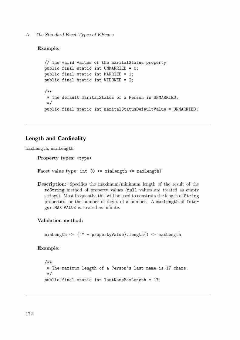
A. The Standard Facet Types of KBeans
Example:
// The valid values of the maritalStatus property
public final static int UNMARRIED = 0;
public final static int MARRIED = 1;
public final static int WIDOWED = 2;
/**
* The default maritalStatus of a Person is UNMARRIED.
*/
public final static int maritalStatusDefaultValue = UNMARRIED;
Length and Cardinality
maxLength, minLength
Property types: <type>
Facet value type: int (0 <= minLength <= maxLength)
Description: Specifies the maximum/minimum length of the result of thetoString method of property values (null values are treated as emptystrings). Most frequently, this will be used to constrain the length of Stringproperties, or the number of digits of a number. A maxLength of Inte-ger.MAX VALUE is treated as infinite.
Validation method:
minLength <= ("" + propertyValue).length() <= maxLength
Example:
/**
* The maximum length of a Person’s last name is 17 chars.
*/
public final static int lastNameMaxLength = 17;
172

fractionDigits
Property types: float, double, float[], double[]
Facet value type: int (fractionDigits >= 0)
Description: Specifies the maximum number of digits of the fractional partof a floating point number.
Validation method:
double fraction = (propertyValue - (int)propertyValue);
("" + fraction).length() - 2 <= facetValue
Example:
/**
* A price can have at most two digits behind the dot.
*/
public final static int priceFractionDigits = 2;
maxCardinality, minCardinality
Property types: <simple>[]
Facet value type: int (0 <= minCardinality <= maxCardinality)
Description: Specifies the maximum/minimum cardinality of indexed prop-erty values (the cardinality of null arrays is 0). A maxCardinality ofInteger.MAX VALUE is treated as infinite.
Validation method:
minCardinality <= propertyValue.length <= maxCardinality
Example:
/**
* A Person that is UNMARRIED cannot have any children.
*/
public int getChildrenMaxCardinality() {
if(getMaritalStatus() == UNMARRIED) {
return 0;
173

A. The Standard Facet Types of KBeans
}
else {
return Integer.MAX_VALUE; // unlimited
}
}
Type Restriction
validClasses
Property types: <object>, <object>[]
Facet value type: Class[]
Description: Constrains the type of valid property values. The facet valuesmust be subclasses of the property type. This constraint is satisfied, if allvalues of the property are either instances of one of the types declared asfacet values, or null.
Validation method:
forall v=propertyValues: facetValues.contains(v.getClass())
Example: (defined in MalePerson class)
/**
* The spouse of a MalePerson must be a FemalePerson.
*/
public final static Class[] spouseValidClasses = {
FemalePerson.class
};
invalidClasses
Property types: <object>, <object>[]
Facet value type: Class[]
Description: Constrains the type of valid property values. The facet valuesmust be subclasses of the property type. This constraint is satisfied, if noneof the values of the property is an instance of one of the types declared asfacet values.
174

Validation method:
!(forall v=propertyValues: facetValues.contains(v.getClass()))
Example: (defined in MalePerson class)
/**
* The spouse of a MalePerson cannot be a MalePerson.
*/
public final static Class[] spouseInvalidClasses = {
MalePerson.class
};
Range by Comparison
maxExclusive, maxInclusive, minExclusive, minInclusive
Property types: <comparable>, <comparable>[]
Facet value type: <comparable>
Description: Specifies the upper/lower bounds of the property value, withregard to Comparable.compareTo.
Validation method:
maxExclusive: propertyValue < facetValue
maxInclusive: propertyValue <= facetValue
minExclusive: propertyValue > facetValue
minInclusive: propertyValue >= facetValue
Example:
/**
* A Person’s (inclusive) minimum age is 0 (age >= 0).
*/
public final static int ageMinInclusive = 0;
175

A. The Standard Facet Types of KBeans
Range by Enumeration
validValues
Property types: <simple>, <simple>[]
Facet value type: <simple>[]
Description: Specifies all valid values of the property. This constraint issatisfied, if all property values are either equal to one of the facet values(using the equals method), or null if null is one of the facet values.
Validation method: propertyV alues ⊆ facetV alues
Example:
/**
* The maritalStatus must be UNMARRIED, MARRIED, or WIDOWED
*/
public final static int[] maritalStatusValidValues = {
UNMARRIED,
MARRIED,
WIDOWED
};
requiredValues
Property types: <simple>, <simple>[]
Facet value type: <simple>[]
Description: Specifies a set of values that must be part of the set of propertyvalues. This constraint is satisfied, if all facet values are equal to one of theproperty values (using the equals method).
Validation method: propertyV alues ⊇ facetV alues
Example:
/**
* The parents of the spouse must be among the guests.
*/
public Person[] getGuestsRequiredValues() {
return (spouse == null) ? null : spouse.getParents();
}
176

invalidValues
Property types: <simple>, <simple>[]
Facet value type: <simple>[]
Description: Specifies invalid values of the property. None of the propertyvalues may be equal to one of the facet values (using the equals method),or null if null is one of the facet values.
Validation method: propertyV alues ∩ facetV alues = ∅
Example:
/**
* A Person cannot be married to one of his/her children.
*/
public Person[] getSpouseInvalidValues() {
return children;
}
notNull
Property types: <type>
Facet value type: boolean
Description: Declares whether null is a valid property value.
Validation method:
facetValue == false || propertyValue != null
Example:
/**
* The lastName must not be null.
*/
public final static boolean lastNameNotNull = true;
177

A. The Standard Facet Types of KBeans
Relationship between Properties
Whereas the above constraint types restrict property values by describing valid and invalidvalues directly, the following constraint types achieve this indirectly by declaring a rela-tionship between the values of the property and those from another property. Since it isvery complicating in Java to refer to other properties by objects (this would mean to returnPropertyDescriptors as facet values), these constraint types declare properties by theirnames, i.e. as Strings. Beside simple references to other properties, they also use propertychains (cf. the slot chains from OKBC). A property chain defines a list of property namesP[0], . . . , P[n], so that the values of the chain are the values of the P[n] property ofthe values of the P[n-1] property. . . of the values of the P[0] property, where P[0] is aproperty of the given class. For example, the values of the property chain ["spouse",
"parents"] are the parents of a person’s spouse.
inverseProperty
Property types: <object>, <object>[]
Facet value type: String (name of a property of the class <object>)
Description: Declares the inverse property in the class that is referenced toby the property type. The property is specified by name. Satisfaction ofthis constraint means that if ref is a property value of the object obj, thenobj is also a value of the inverse property of ref.
Validation method:
forall v=propertyValues: v.inverseProperty.contains(obj)
Example:
/**
* The inverse property of children is parents.
*/
public final static String childrenInverseProperty="parents";
equalProperty
Property types: <type>
Facet value type: String[] (a property chain)
178

Description: Declares that the property values must be equal to the valuesof another property that is specified by a property chain. This constraintis satisfied if both sets of values are equal, whereby the single elements arecompared with equals.
Validation method: propertyV alues = chainV alueSet(facetV alues)
Example:
/**
* A person’s children are equal to the spouse’s children.
*/
public final static String[] childrenEqualProperty = {
"spouse", "children"
};
unequalProperty
Property types: <type>
Facet value type: String[] (a property chain)
Description: Declares that the sets of values of the given property and thoseof a specified property chain must not be completely equal.
Validation method: propertyV alues �= chainV alueSet(facetV alues)
Example:
/**
* A person’s parents must be different from the
* spouse’s parents.
*/
public final static String[] parentsUnequalProperty = {
"spouse", "parents"
};
179

A. The Standard Facet Types of KBeans
validValuesProperty, requiredValuesProperty, invalidValuesProperty
Property types: <type> (or <type>[] for requiredValuesProperty)
Facet value type: String[] (a property chain)
Description: Declares the valid/invalid/required property values by referringto the values of a specified property chain. The semantics are comparableto the related facet types validValues, requiredValues, and invalid-
Values.
Validation methods:valid. . . : propertyV alues ⊆ chainV alueSet(facetV alues)required. . . : propertyV alues ⊇ chainV alueSet(facetV alues)invalid. . . : propertyV alues ∩ chainV alueSet(facetV alues) = ∅
Example:
/**
* A person cannot be married to one of his/her children.
*/
public final static String[] spouseInvalidValuesProperty = {
"children"
};
Lexical Pattern Matching
pattern
Property types: <type>
Facet value type: String
Description: Declares a regular expression in the notation of Perl whichis used by both the java.util.regex package of Java 1.4 and the XMLSchema facet pattern [200]. The constraint is satisfied, if the toString rep-resentation of each of the property values matches this expression (wherebynull.toString() is "").
Validation method:
forall v=propertyValue: Pattern.matches(facetValue, "" + v);
180

Example:
/**
* The zipCode must match the pattern "[0-9]{5}(-[0-9]{4})?".
*/
public final static String zipCodePattern =
"[0-9]{5}(-[0-9]{4})?";
Collection Type
ordered
Property types: <comparable>[]
Facet value type: boolean
Description: Declares whether the property values must be in ascending order(using the Comparable.compareTo method).
Validation method:
!facetValue ||
forall i: propertyValue[i].compareTo(propertyValue[i+1] <= 0
Example:
/**
* Children must be ordered by age (using Person.compareTo).
*/
public final static boolean childrenOrdered = true;
duplicateFree
Property types: <simple>[]
Facet value type: boolean
Description: Declares whether the property values may contain duplicates(using the equals method).
Validation method:
181

A. The Standard Facet Types of KBeans
!facetValue ||
(forall i!=j: !propertyValue[i].equals(propertyValue[j])
Example:
/**
* The list of firstNames must be duplicate-free.
*/
public final static boolean firstNamesDuplicateFree = true;
Textual Representation
validValuesNames
Property types: <type>
Facet value type: String[]
Description: Defines a textual representation of all the property value(s) de-clared with the validValues constraint. Each of the results of validValuesmust have one corresponding name element. For example, this facet can beused to define human-readable values of primitive constants for GUI ele-ments (e.g., radio buttons and combo boxes). It can serve as a replacementfor the missing support of enumeration types in Java.
Example:
public final static String[] maritalStatusValidValuesNames={
"unmarried", // [0] = UNMARRIED
"married", // [1] = MARRIED
"widowed" // [2] = WIDOWED
};
182

B. A Sample KBeans Ontology Class
The following Java source code implements the Person class from the sample ontologyfrom figure 5.4 (page 66).
package demo.person;
import de.faw.kbeans.java.*;
import java.util.*;
/**
* A simple JavaBeans class to test various KBeans constraints.
*
* @author Holger Knublauch
* @author Martin Sedlmayr
*/
public abstract class Person extends AbstractKBean
implements Comparable, NamedBean {
// age property ------------------------------------------------------
/**
* The value of the age property
*/
private int age;
/**
* A Person’s minimum age is 0
*/
public final static int ageMinInclusive = 0;
/**
* Gets the Person’s age.
* @return the age
*/
183

B. A Sample KBeans Ontology Class
public int getAge() {
return age;
}
/**
* Set the value of the age.
* @param value the value to assign
* @see #ageMinInclusive
*/
public void setAge(int value) {
int old = age;
age = value;
firePropertyChange("age", old, age);
}
// children property -------------------------------------------------
/**
* The value of the children property
*/
private Person[] children;
/**
* The children must be duplicate-free
*/
public final static boolean childrenDuplicateFree = true;
/**
* A Person’s children must be ordered (by age)
*/
public final static boolean childrenOrdered = true;
/**
* Gets the children.
* @return the children or null
*/
public Person[] getChildren() {
return children;
}
184

/**
* A Person that is UNMARRIED cannot have any children.
*/
public int getChildrenMaxCardinality() {
if(getMaritalStatus() == UNMARRIED) {
return 0;
}
else {
return Integer.MAX_VALUE; // unlimited
}
}
/**
* Sets the children.
* @param values the new children or null
* @see #childrenDuplicateFree
* @see #childrenOrdered
* @see #getChildrenMaxCardinality
*/
public void setChildren(Person[] values) {
Object old = children;
children = values;
firePropertyChange("children", old, values);
}
// firstNames property -----------------------------------------------
/**
* The value of the firstNames property
*/
private String[] firstNames;
/**
* The firstNames must be distinct
*/
public final static boolean firstNamesDuplicateFree = true;
/**
* Gets the first names.
185

B. A Sample KBeans Ontology Class
* @return the first names or null
*/
public String[] getFirstNames() {
return firstNames;
}
/**
* Sets the firstNames.
* @param values the new firstNames or null
* @see #firstNamesDuplicateFree
*/
public void setFirstNames(String[] values) {
Object old = firstNames;
firstNames = values;
firePropertyChange("firstNames", old, values);
}
// lastName property -------------------------------------------------
/**
* The current value of the lastName property
*/
private String lastName;
/**
* The maximum length of a Person’s last name is 17 chars.
*/
public final static int lastNameMaxLength = 17;
/**
* The lastName must not be null.
*/
public final static boolean lastNameNotNull = true;
/**
* Gets the value of the lastName property.
* @return the lastName
* @see #setLastName
*/
186

public String getLastName() {
return lastName;
}
/**
* Sets the value of the lastName property.
* @param value the new lastName
* @see #lastNameMaxLength
* @see #lastNameNotNull
*/
public void setLastName(String value) {
Object old = lastName;
lastName = value;
firePropertyChange("lastName", old, value);
}
// maritalStatus property --------------------------------------------
// The valid values of the maritalStatus property
public final static int UNMARRIED = 0;
public final static int MARRIED = 1;
public final static int WIDOWED = 2;
/**
* The current value of the maritalStatus property
*/
private int maritalStatus = UNMARRIED;
/**
* The default maritalStatus of a Person is UNMARRIED.
*/
public final static int maritalStatusDefaultValue = UNMARRIED;
/**
* The maritalStatus must be UNMARRIED, MARRIED, or WIDOWED
*/
public final static int[] maritalStatusValidValues = {
UNMARRIED,
MARRIED,
WIDOWED
};
187

B. A Sample KBeans Ontology Class
public final static String[] maritalStatusValidValuesNames = {
"unmarried", // [0] = UNMARRIED
"married", // [1] = MARRIED
"widowed" // [2] = WIDOWED
};
/**
* Gets the marital status.
* @return the marital status
*/
public int getMaritalStatus() {
return maritalStatus;
}
/**
* Sets the maritalStatus.
* @param value the new maritalStatus
* @see #maritalStatusValidValues
* @see #maritalStatusValidValuesNames
*/
public void setMaritalStatus(int value) {
int old = maritalStatus;
maritalStatus = value;
firePropertyChange("maritalStatus", old, value);
}
// spouse property ---------------------------------------------------
/**
* The value of the spouse property
*/
private Person spouse;
/**
* Gets the spouse.
* @return the spouse
188

*/
public Person getSpouse() {
return spouse;
}
/**
* A Person’s spouse may not be one of the children.
*/
public Person[] getSpouseInvalidValues() {
return children;
}
/**
* The spouse must not be null, if the maritalStatus is MARRIED.
*/
public boolean isSpouseNotNull() {
return getMaritalStatus() == MARRIED;
}
/**
* Sets the spouse.
* @param value the new spouse
* @see #getSpouseInvalidValues
* @see #isSpouseNotNull
*/
public void setSpouse(Person value) {
Object old = spouse;
spouse = value;
firePropertyChange("spouse", old, value);
}
// constructors & methods --------------------------------------------
/**
* Constructs a new Person.
*/
public Person() {
}
189

B. A Sample KBeans Ontology Class
/**
* Defines an ordering among Persons, with respect to age.
* @param other the object to compare to (usually a Person)
* @return the other’s age compared to this age
*/
public int compareTo(Object other) {
if(other instanceof Person) {
int oa = ((Person)other).age;
if(age < oa) {
return -1;
}
else
if(age > oa) {
return 1;
}
}
return 0;
}
/**
* Gets an object’s name that appears in visual representations (e.g.
* a KBeansShell). Implements <CODE>NamedBean</CODE>.
* @return the lastName or null
*/
public String getBeanName() {
return lastName;
}
/**
* Used by the KBeans introspection mechanism to locate the subclasses
* of this class (e.g. in a KBeansShell). Required since there is no
* Java standard way to forward-reference subclasses.
*/
static {
KBeansIntrospector.installClass(MalePerson.class);
KBeansIntrospector.installClass(FemalePerson.class);
}
}
190

C. A Sample KBeans Constraint Class
The following Java source code defines the KBeans constraint type “maximum cardinality”.The constraint allows to specify the maximum size of indexed (array) properties.
package de.faw.kbeans.facets.core;
import de.faw.kbeans.*;
import de.faw.kbeans.facets.*;
/**
* A RepairableConstraintType for indexed properties, which specifies
* the maximum length of the array.
* @author Holger Knublauch
*/
public class MaxCardinalityConstraintType extends AbstractFacetType
implements RepairableConstraintType {
public MaxCardinalityConstraintType() {
super("MaxCardinality");
}
// Implements ConstraintType
public String toString(BeanModel beanModel, Object facet) {
return "Maximum cardinality of " +
BeanModelTools.getBeanDescription(beanModel, facet) +
" expected";
}
/**
* The facet type is int.
* @return <CODE>int.class</CODE>
*/
public Object getFacetType(BeanModel beanModel, Object valueType) {
return int.class;
}
191

C. A Sample KBeans Constraint Class
/**
* Removes the end of the array, in order to match the maximum length.
*/
public Object getValidValue(BeanModel beanModel,
Object bean, Object property,
Object facet, Object value) {
if(value == null) {
return null;
}
else {
int max = ((Number)facet).intValue();
Object cls = beanModel.getClass(bean);
Object ct = beanModel.getPropertyType(cls, property);
Object neu = beanModel.createArray(ct, max);
beanModel.arraycopy(value, 0, neu, 0, max);
return neu;
}
}
/**
* This Constraint is applicable to indexed types only.
*/
public boolean isAdmissibleValueType(BeanModel beanModel, Object type) {
return beanModel.isIndexedType(type);
}
/**
* A value is invalid, if it is null, or its length is <= the maximum length.
*/
public boolean isValidValue(BeanModel beanModel,
Object bean, Object property,
Object facet, Object value) {
if(facet instanceof Number) {
int max = ((Number)facet).intValue();
int len = (value == null) ? 0 : beanModel.getArrayLength(value);
return len <= max;
}
return true;
}
}
192

D. The Facets of XML Schema
XML Schema [200] is an XML-based specification language for describing the syntax andsemantics of a class of XML documents. XML Schema documents can be used to definesimple elements (comparable to the primitive types of Java such as int and boolean)and complex elements (which can be built by combining other elements, comparable toclasses in Java). New simple element types are defined by deriving them from existingsimple types, e.g. by building lists of other types. In particular, it is possible to derive anew simple type by restricting an existing simple type. The legal range of values for thenew type is a subset of the existing type’s range of values. Restrictions (or constraints) aredefined by means of so-called facets. Every facet has a name that is associated to predefinedsemantics, and a value of a type that can be uniquely derived from the simple element typethat is constrained by the facet. For example, the facet named minExclusive defines theexclusive lower bound (using >) of a numerical element. The value of the minExclusive
facet must be of the same type as the simple element, e.g. int for int elements. In orderto cover the most frequently needed types of metadata, XML Schema provides a set ofstandard facet types, which is summarized in table D.1.
193

D. The Facets of XML Schema
Table D.1.: The constraining facets of XML Schema.
Facet name Value type Facet type Semanticslength string, list int (≥0) (Exact) string or list length.minLength* string, list int (≥0) Minimum string or list length.maxLength* string, list int (≥0) Maximum string or list length.pattern <type> reg. expr. Lexical space of the values.enumeration <type> <type>[] Enumeration of valid values.whitespace <type> (3 options) Preserve, replace, or collapse whitespaces.maxInclusive <ordered> <type> Inclusive upper bound (≤).maxExclusive <ordered> <type> Exclusive upper bound (<).minInclusive <ordered> <type> Inclusive lower bound (≥).minExclusive <ordered> <type> Exclusive lower bound (>).totalDigits <decimal> int (>0) Maximum number of digits.fractionDigits <decimal> int (≥0) Maximum length of the fractional part.
*Similar to minLength and maxLength, which constrain simple types, XMLSchema supports minOccurs and maxOccurs declarations for complex types.
194

E. The BeanModel Java interface
This appendix lists the signatures of the core methods of the Java interface BeanModel.The methods are grouped by their functionality.
public interface BeanModel {
// Creation and analysis of beans (objects)
Object createBean(Object cls);
String getBeanName(Object bean);
Object getClass(Object bean);
// Analysis of classes
Object getBeanClassType();
Object getClassByName(String clsName);
String getClassName(Object cls);
Class getCustomizerClass(Object cls);
Object getComponentType(Object type);
Object[] getKnownSubClasses(Object cls);
Object[] getPrimitiveProperties(Object cls);
Object[] getProperties(Object cls);
Object getPropertyByName(Object cls, String propertyName);
PropertyEditor getPropertyEditor(Object cls);
Object[] getRefProperties(Object cls);
Object getSuperClass(Object cls);
boolean isAbstractClass(Object cls);
boolean isComparableType(Object cls);
boolean isIndexedType(Object cls);
boolean isRefType(Object cls);
boolean isSubClass(Object cls, Object subClass);
// Analysis and manipulation of properties
String getPropertyName(Object cls, Object property);
Object getPropertyType(Object cls, Object property);
Object getPropertyValue(Object bean, Object property);
Object getPropertyValue(Object bean, Object property, int index);
195

E. The BeanModel Java interface
int getPropertyValueCount(Object bean, Object property);
void insertPropertyValue(Object bean, Object property,
int index, Object value);
boolean isIndexedProperty(Object cls, Object property);
void removePropertyValue(Object bean, Object property, int index);
void setPropertyValue(Object bean, Object property, Object value);
void setPropertyValue(Object bean, Object property,
int index, Object value);
// PropertyChangeListener management
void addPropertyChangeListener(Object bean, PropertyChangeListener l);
void addPropertyChangeListener(Object bean, Object property,
PropertyChangeListener l);
void removePropertyChangeListener(Object bean,
PropertyChangeListener l);
void removePropertyChangeListener(Object bean, Object property,
PropertyChangeListener l);
// Constraint checking
ConstraintViolation createConstraintViolation(Object bean,
Object property, Object context, Object value, Constraint c);
Object getConstraintContext(Object bean, Object property, Constraint c);
Constraint getPropertyConstraint(Object cls, Object property, Class cc);
Iterator getPropertyConstraints(Object cls, Object property);
// Object graph management
Object getRootBean();
Object getRootBeanProperty();
BeanModelSet getBeanModelSet();
void setRootBeanPropertyType(Object cls);
}
196

F. Class Diagram of the Meta ObjectFacility (MOF)
+name
ModelElement
Namespace Constraint TypedElement
GeneralizableElement
Package Classifier
DataTypeAssociation Class
BehavorialFeature
Feature
Operation Exception
StructuralFeature
Attribute Reference
AssociationEnd
+type
1
+typedElement
0..*
+referent 0..*
+referenceEnd 1
+referrer
0..*
+exposedEnd
1
Figure F.1.: Some of the core classes of the Meta Object Facility.
197


G. Java Libraries for Knowledge-BasedSystems and Artificial Intelligence
This appendix provides a catalogue of Java libraries that support functionality which istypically assigned to knowledge-based or Artificial Intelligence systems. Please note thatmany of these projects are research prototypes, so that the given links might be outdated.
CommonRules
http://www.research.ibm.com/rules/home.html
Rule-based business processes for e-commerce.
ECJ
http://www.cs.umd.edu/projects/plus/ec/ecj
A Java-based Evolutionary Computation and Genetic Programming Research System.
FIPA-OS
http://fipa-os.sourceforge.net
An open-source multi-agent platform in Java.
Java Agent Services
http://www.java-agent.org
The (forthcoming) Java standard extension on multi-agent systems.
Java Rule Engine
http://jcp.org/jsr/detail/94.jsp
A Java Community Process that defines a Java runtime API for rule engines.
JCL (Java Constraint Library)
http://liawww.epfl.ch/~torrens/Project/JCL
Application services related with binary Constraint-Satisfaction Problems.
199
G. Java Libraries for Knowledge-Based Systems and Artificial Intelligence
JESS (Java Expert System Shell)
http://herzberg.ca.sandia.gov/jess
A rule engine and scripting environment, based on the RETE algorithm.
SPIRIT
http://www.xspirit.de
A Java tool and API providing probabilistic reasoning functionality.
WEKA
http://www.cs.waikato.ac.nz/~ml/weka
Machine learning software in Java, particularly data mining algorithms.
200

H. The KBeans Logic package
Expression
+evaluate() : Object
EvaluableExpression
+evaluateBoolean() : Boolean
BooleanExpression
+evaluateDiscrete() : DiscreteValue
DiscreteExpression
+evaluateDouble() : double
NumericExpression
+first : EvaluableExpression+second : EvaluableExpression
Equals
+expression : BooleanExpression
Not
+first : BooleanExpression+second : BooleanExpression
BooleanOperand
Equivalent
Implies
And
Or
+first : NumericExpression+second : NumericExpression
NumericComparison
Greater
Less
+value : double
Number
+first : NumericExpression+second : NumericExpression
NumericOperand
+expression : NumericExpression
Negation
+name : String
NumericVariable
MultiplicativeOperand AdditiveOperand
Mult
Div Minus
Plus
+name : String
DiscreteValue
+values : DiscreteValue
DiscreteVariable
These classes must beoverloaded to customize the
logic to the application domain.
Figure H.1.: A generic library of KBeans classes for the representation and evaluation oflogical rules.
201


Curriculum Vitae
Holger Knublauch was born on July 7th, 1971 in Berlin-Lichterfelde, Germany. Afterhaving passed the Abitur (high school graduation) in Hagen, Germany, in 1991, and themandatory military service, he started studying Computer Science with Economics asminor at the University of Dortmund, Germany, in 1992. Following the completion ofhis Vordiplom (intermediate diploma) in Dortmund, he moved to the University of Ulm,Germany, where he graduated on a masters thesis on object-oriented software developmentof a probabilistic knowledge-based system in March, 1997. In 1997, he gathered workingexperience as software developer in a New Zealand-based teachware company. In 1998,he became a member of the Department of Business Processes and Telematics at theResearch Institute for Applied Knowledge Processing (FAW), Ulm, Germany. He worked invarious research and development projects with a focus on knowledge and process modeling.The main ideas of this PhD thesis have emerged from the projects ANIS (AnesthesiaInformation System) and AGIL (Agent-based Information Logistics), where Holger was theprincipal researcher. In addition to his work at the FAW, in 2001 he started working as alecturer for application development at the University of Applied Sciences (Fachhochschule)Neu-Ulm, Germany, and as a lecturer and project coach in Extreme Programming coursesat the University of Ulm, Germany.

Zusammenfassung
Das Ziel dieser Arbeit ist es die Entwicklung wissensbasierter Systeme effizienter zu machen.Zu diesem Zweck schlagt die Arbeit eine neue, agile Software- und Knowledge Engineering-Methode vor, die mit XP.K (eXtreme Programming of Knowledge-based systems) bezeich-net wird. Diese Methode basiert auf den vier Werten Einfachheit, Gemeinschaft, Feedbackund Eigenverantwortung, und wendet objektorientiertes Round-Trip Engineering auf dieWissensmodellierung an.
Grundlage der Arbeit ist die Beobachtung, dass Wissen fur die meisten wissensbasiertenSysteme notwendigerweise in einer evolutionaren Weise modelliert werden muss, wobeiFachexperten und Ingenieure eng zusammenarbeiten mussen. Der Autor zeigt, dass dieexistierenden ,,schwergewichtigen” Entwicklungsmethoden der objektorientierten Software-technik und aus dem Knowledge Engineering oft ineffizient sind, weil sie hohe Kostenfur Anderungen in den Wissensmodellen nach sich ziehen. Außerdem stellen sie wenigUnterstutzung fur die Ubergange zwischen Wissen, Wissensmodellen und dem restlichenausfuhrbaren System bereit. Der Ausgangspunkt von XP.K ist die Hypothese, dass ,,lei-chtgewichtige” – oder agile – Entwicklungsprozesse (wie z.B. Extreme Programming) furdie Wissensmodellierung geeignet sind, weil sie fur Projekte mit haufig sich anderndenAnforderungen optimiert sind, und zudem mit einem Minimum an Modellierungsartefaktenauskommen zwischen denen recht reibungslose Ubergange moglich sind.
XP.K wendet die wesentlichen Prinzipien von Extreme Programming auf das Feld derWissensmodellierung an. Der Entwicklungsprozess legt großen Wert auf Kommunikation.Fachexperten und Wissensingenieure arbeiten eng bei der Definition von Metamodellen(Ontologien) zusammen, und Wissen wird jeweils zu zweit akquiriert und getestet. On-tologien werden in derjenigen (objektorientierten) Sprache implementiert, die auch fur dierestlichen Systemmodule verwendet wird. Diese Ontologien machen ihre Struktur sowohlzur Laufzeit als auch zur Entwurfszeit auf transparente Art und Weise nach außen hin sicht-bar. Zur Laufzeit wird Reflection verwendet um die Ontologie zu analysieren, sodass gener-ische Wissensmodellierungswerkzeuge und Inferenzmaschinen (wieder-) verwendet werdenkonnen. Zur Entwurfszeit wird Round-Trip Engineering eingesetzt um die Struktur derOntologie nach UML umzuwandeln, sodass die gesamten Informationen und Dokumenta-tionen zur Ontologie zentral im Quellcode abgelegt werden konnen. Ausfuhrbare Proto-typen werden schnell erzeugt und in kurzen Zyklen mit Hilfe von automatischen Tests undConstraint-Checks evaluiert.
XP.K wird durch einen umfangreichen, direkt einsetzbaren Satz an Basissoftware un-terstutzt. Dieser beinhaltet eine Erweiterung des Java-Komponentenmodelles JavaBeanszur Darstellung von semantischen Constraints uber Objektzustande, und eine generischePlattform fur Wissensmodellierungswerkzeuge. Die Effizienz von XP.K wird durch Fall-studien untermauert, z.B. anhand eines klinischen entscheidungsunterstutzenden Systemsund eines Prozessmodellierungsansatzes fur Multi-Agenten-Systeme.