Embed Size (px)
Citation preview
N A S A TECHNICAL NOTE
AN ALGORITHM FOR DIGITAL RESOLUTION OF RANGE FOR V/STOL AIRCRAFT
by Gilbert G. Robinson and Michael J. Bondi
Ames Resedrch Center Moffett Field, Gal$ 94035
N A T I O N A L AERONAUTICS A N D SPACE A D M I N I S T R A T I O N W A S H I N G T O N , D. C. M A R C H 1971 i
https://ntrs.nasa.gov/search.jsp?R=19710009091 2018-07-11T19:46:47+00:00Z
- -
TECH LIBRARY KAFB, NM
4. Title and Subtitle AN ALGORITHM FOR DIGITAL RESOLUTION OF RANGE
FOR V/STOL AIRCRAFT
7. Author(s)
Gilbert G. Robinson and Michael J. Bondi
9. Performing Organization Name and Address
NASA Ames Research Center Moffett Field, Calif., 94035
2. Sponsoring Agency Name and Address
National Aeronautics and Space Administration Washington, D.C. 20546
5. Supplementary Notes
. -~ 16. Abstract
llllllllllllllllllllllillllllllllllllllllllll 5. Report Date
March 1971 6. Performing Organization Code
8. Performing Organization Report No.
A-2842 10. Work Unit No.
125- 17-03-01 -00-21
11. Contract or Grant No.
13.Type of Report and Period Covered
Technical Note
14. Sponsoring Agency Code
I
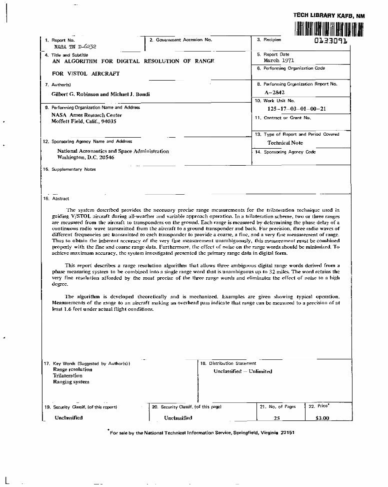
The system described provides the necessary precise range measurements for the trilateration technique used in guiding V/STOL aircraft during all-weather and variable approach operation. In a trilateration scheme, two or three ranges are measured from the aircraft to transponders on the ground. Each range is measured by determining the phase delay of a continuous radio wave transmitted from the aircraft to a ground transponder and back. For precision, three radio waves of different frequencies are transmitted to each transponder to provide a coarse, a fine, and a very fine measurement of range. Thus to obtain the inherent accuracy of the very fine measiirement unambiguously, this measurement most be combined properly with the fine and coarse range data. Furthermore, the effect of noise on the range words should be minimized. To achieve maximum accuracy, the system investigated presented the primary range data in digital form.
This report describes a range resolution algorithm that allows three ambiguous digital range words derived from a phase measuring system to be combined into a single range word that is unambiguous up to 32 miles. The word retains the very fine resolution afforded by the most precise of the three range words and eliminates the effect of noise to a high degree.
The algorithm is developed theoretically and is mechanized. Examples are given showing typical operation. Measurements of the range to an aircraft making an overhead pass indicate that range can be measured to a precision of a t least 1.6 feet under actual flight conditions.
17. Key Words (Suggested by Author(s) ) Range resolution Trilatera tion Ranging system
-19. Security Classif. (of this report)
Unclassified
. 18. Distribution Statement
Unclassified - Unlimited
. I20. Security Classif. (of this page) 21.NO. of Pages 22. Price"
Unclassified ~~ 25 $3.00
TABLE OF CONTENTS
Page RANGE ALGORITHM GLOSSARY . . . . . . . . . . . . . . . . . . . . . . . . . . . . . . . . V
SUMMARY . . . . . . . . . . . . . . . . . . . . . . . . . . . . . . . . . . . . . . . . . . . . . . . 1 INTRODUCTION . . . . . . . . . . . . . . . . . . . . . . . . . . . . . . . . . . . . . . . . . . . 1 THE RANGE MEASURING SYSTEM . . . . . . . . . . . . . . . . . . . . . . . . . . . . . . 2
Noise Compensation . . . . . . . . . . . . . . . . . . . . . . . . . . . . . . . . . . . . . . . . 4 Evolution of the Procedure . . . . . . . . . . . . . . . . . . . . . . . . . . . . . . . . . . . . 6 Application of the Range Algorithm to Binary Numbers . . . . . . . . . . . . . . . . . . . 7 Procedure Details Related to the Precision Range Measuring System . . . . . . . . . . . . . 13
OCTAL ARITHMETIC . . . . . . . . . . . . . . . . . . . . . . . . . . . . . . . . . . . . . . . . 13 COMPLETE EXAMPLE . . . . . . . . . . . . . . . . . . . . . . . . . . . . . . . . . . . . . . . . 13 FLIGHT CONFIRMATION . . . . . . . . . . . . . . . . . . . . . . . . . . . . . . . . . . . . . 16 CONCLUDINGREMARKS . . . . . . . . . . . . . . . . . . . . . . . . . . . . . . . . . . . . . . 19 REFERENCE . . . . . . . . . . . . . . . . . . . . . . . . . . . . . . . . . . . . . . . . . . . . . . 19
... 111
L

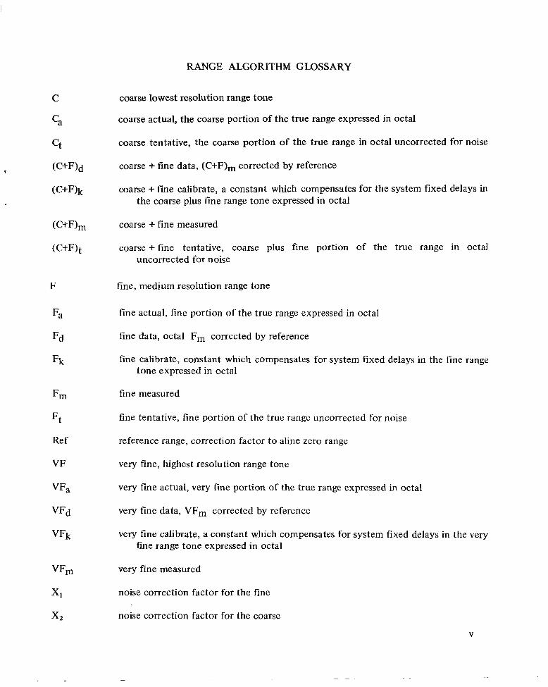
RANGE ALGORITHM GLOSSARY
F
Fa
Fd
Fk
Fm
Ft
Ref
VF
VFa
VFd
VFk
coarse lowest resolution range tone
coarse actual, the coarse portion of the true range expressed in octal
coarse tentative, the coarse portion of the true range in octal uncorrected for noise
coarse + fine data, (C+F)m corrected by reference
coarse + fine calibrate, a constant which compensates for the system fixed delays in the coarse plus fine range tone expressed in octal
coarse + fine measured
coarse +fine tentative, coarse plus fine portion of the true range in octal uncorrected for noise
fine, medium resolution range tone
fine actual, fine portion of the true range expressed in octal
fine data, octal Fm corrected by reference
fine calibrate, constant which compensates for system fixed delays in the fine range tone expressed in octal
fine measured
fine tentative, fine portion of the true range uncorrected for noise
reference range, correction factor t o aline zero range
very fine, highest resolution range tone
very fine actual, very fine portion of the true range expressed in octal
very fine data, VFm corrected by reference
very fine calibrate, a constant which compensates for system fixed delays in the very tine range tone expressed in octal
very fine measured
noise correction factor for the fine
noise correction factor for the coarse
V
AN ALGORITHM FOR DIGITAL RESOLUTION OF RANGE
FOR V/STOL AIRCRAFT
Gilbert G. Robinson and Michael J. Bondi
Ames Research Center
SUMMARY
The system described provides the necessary precise range measurements for the trilateration technique used in guiding V/STOL aircraft during all-weather and variable approach operation. In a trilateration scheme, two or three ranges are measured from the aircraft to transponders on the ground. Each range is measured by determining the phase delay of a continuous radio wave transmitted from the aircraft to a ground transponder and back. For precision, three radio waves of different frequencies are transmitted to each transponder to provide a coarse, a fine, and a very fine measurement of range. Thus to obtain the inherent accuracy of the very fine measurement unambiguously, this measurement must be combined properly with the fine and coarse range data. Furthermore, the effect of noise on the range words should be minimized. To achieve maximum accuracy, the system investigated presented the primary range data in digital form.
This report describes a range resolution algorithm that allows three ambiguous digital range words derived from a phase measuring system to be combined into a single range word that is unambiguous up to 32 miles. The word retains the very fine resolution afforded by the most precise of the three range words and eliminates the effect of noise to a high degree.
The algorithm is developed theoretically and is mechanized. Examples are given showing typical operation. Measurements of the range to an aircraft making an overhead pass indicate that range can be measured to a precision of at least 1.6 feet under actual flight conditions.
INTRODUCTION
The development of V/STOL-type aircraft to fly short-haul feeder routes between major airports and outlying areas offers promise to solving many of today’s perplexing air traffic problems. To avoid congestion, minimize noise, or improve safety, these aircraft can land on short runways and are capable of making various types of approaches (e.g., straight in, circular, steep). However, to realize the full potential of V/STOL aircraft during all-weather operation, the aircraft position must be known accurately. Therefore, a guidance system for the curved or steep landing approaches will be essential. Consequently, a general investigation was undertaken to determine the navigation requirements for an all-weather landing system that would permit a pilot to land a V/STOL aircraft under low visibility conditions by referring to a visual display (ref. 1).
For such a guidance system position could be determined in several ways. The trilateration concept discussed in this report determines the aircraft position, relative to a fixed coordinate
system that originates on the runway, by three slant range measurements from the aircraft to fixed transponders on the ground, or by two ranges and radio altitude. When these measurements are made aboard the aircraft, a digital computer can determine the aircraft position very rapidly, but the accuracy of the computed position coordinates depends on both the accuracy of the range measurements and the geometry of the aircraft with respect to the transponders.
For this investigation, a range measurement system of extreme basic accuracy was selected. The system allowed precise reference measurements to be made, and also provided the flexibility of deliberately degrading the basic measurements so as to investigate the effects of range errors that might occur in other less precise but perhaps more economically attractive systems. +
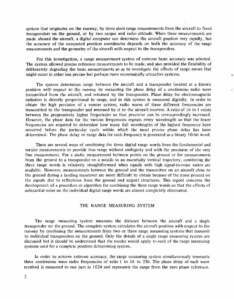
The system determines range between the aircraft and a transponder located at a known position with respect to the runway by measuring the phase delay of a continuous radio wave transmitted from the aircraft, and returned by the transponder. Phase delay for electromagnetic radiation is directly proportional to range, and in this system is measured digitally. In order to obtain the high precision of a vernier system, radio waves of three different frequencies are transmitted to the transponder and returned by it to the aircraft receiver. A ratio of 16 to 1 exists between the progressively higher frequencies so that precision can be correspondingly increased. However, the phase data for the various frequencies repeats every wavelength so that the lower frequencies are required to determine how many full wavelengths of the highest frequency have occurred before the particular cycle within which the most precise phase delay has been determined. The phase delay or range data for each frequency is generated as a binary 10-bit word.
There are several ways of combining the three digital range words from the fundamental and vernier measurements to provide true range without ambiguity and with the precision of the very fine measurement. For a static measurement between points on the ground or for measurements from the ground to a transponder on a missiIe in an essentially vertical trajectory, combining the three range words is relatively straightforward when signals with high signal-to-noise ratios are available. However, measurements between the ground and the transmitter on an aircraft close to the ground during a landing maneuver are more difficult to obtain because of the noise present on the signals due to reflections from the ground and airport structures. This report concerns the development of a procedure or algorithm for combining the three range words so that the effects of substantial noise on the individual digital range words are almost completely eliminated.
THE RANGE MEASURING SYSTEM
The range measuring system measures the distance between the aircraft and a single transponder on the ground. The complete system calculates the aircraft position with respect to the runway by combining the measurements from two or three range measuring systems that transmit to individual transponders on the ground. Only the details of a single range measuring system are discussed but it should be understood that the results would apply to each of the range measuring systems used for a complete position determining system.
In order to achieve extreme accuracy, the range measuring system simultaneously transmits three continuous wave radio frequencies of ratio 1 to 16 to 256. The phase delay of each wave received is measured to one part in 1024 and represents the range from the zero phase reference.
2
I
1 2 3 4 5 6 7 8 9
- -
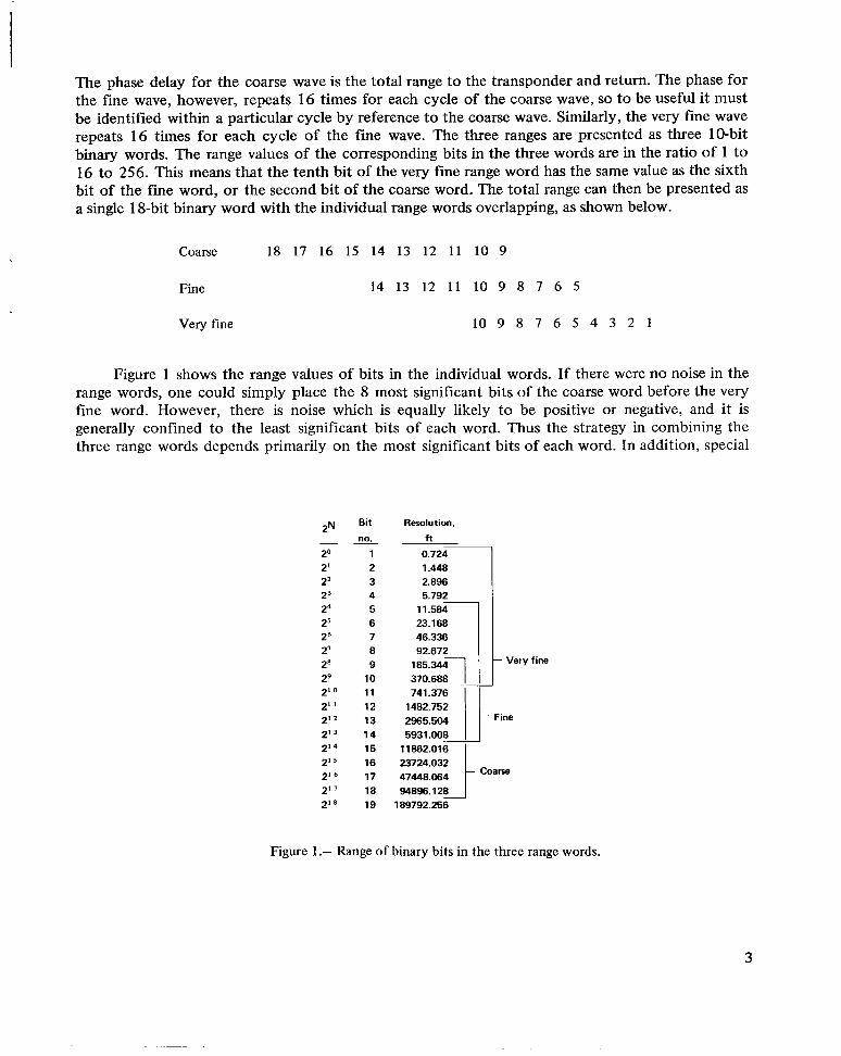
The phase delay for the coarse wave is the total range to the transponder and return. The phase for the fine wave, however, repeats 16 times for each cycle of the coarse wave, so to be useful it must be identified within a particular cycle by reference to the coarse wave. Similarly, the very fine wave repeats 16 times for each cycle of the fine wave. The three ranges are presented as three 10-bit binary words. The range values of the corresponding bits in the three words are in the ratio of 1 to 16 to 256. This means that the tenth bit of the very fine range word has the same value as the sixth bit of the fine word, or the second bit of the coarse word. The total range can then be presented as a single 18-bit binary word with the individual range words overlapping, as shown below.
Coarse 18 17 16 15 14 13 12 11 10 9
Fine 14 13 12 11 10 9 8 7 6 5
Very fine 10 9 8 7 6 5 4 3 2 1
Figure 1 shows the range values of bits in the individual words. If there were no noise in the range words, one could simply place the 8 most significant bits of the coarse word before the very fine word. However, there is noise which is equally likely to be positive or negative, and it is generally confined to the least significant bits of each word. Thus the strategy in combining the three range words depends primarily on the most significant bits of each word. In addition, special
2~ Bit Resolution,
no. f t
20 0.724 21 22 23 24 25 26 46.336 27 92.672 28 Very fine
29 io 370.688 210 1 1 741.376 2" 12 1482.752 212 13 2965.504 Fine
213 14 5931.008 214 15 11862.016 215 16 23724.032 216 17 47448.064 217 18 94896.128 2'8 19 189792.256
Figure 1.- Range of binary bits in the three range words.
3
. . -.
precautions, such as crystal filters, are used for the very fine word since its least significant bits cannot be compensated as may be seen above (bits 1, 2, 3, and 4). Essentially, the final 18-bit range word was constructed from the entire very fine word, the four most significant bits of the fine word, and the four most significant bits of the coarse word. However, a detailed consideration of the effects of noise in the three words led to some modification of the above simple approach, which is reflected in the final algorithm (fig. 4).
Noise Compensation
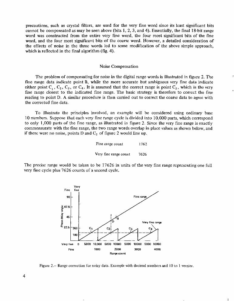
The problem of compensating for noise in the digital range words is illustrated in figure 2. The fine range data indicate point Bywhile the more accurate but ambiguous very fine data indicate either point C, , C 2 , C3, or C4. It is assumed that the correct range is point C , ,which is the very fine range closest to the indicated fine range. The basic strategy is therefore to correct the fine reading to point D. A similar procedure is then carried out to correct the coarse data to agree with the corrected fine data.
To illustrate the principles involved, an example will be considered using ordinary base 10 numbers. Suppose that each very fine range cycle is divided into 10,000 parts, which correspond to only 1,000 parts of the fine range, as illustrated in figure 2. Since the very fine range is exactly commensurate with the fine range, the two range words overlap in place values as shown below, and if there were no noise, points D and Cz of figure 2 would line up.
Fine range count 1762
Very fine range count 7626
The precise range would be taken to be 17626 in units of the very fine range representing one full very fine cycle plus 7626 counts of a second cycle.
Very Fine fine
Veryfine 0 5000 10,000 5000 10000 5000 10000 5000 10000
Fine 1000 2000 3000 4000 Range count
Figure 2.- Range correction for noisy data. Example with decimal numbers and 10 to 1 vernier
4
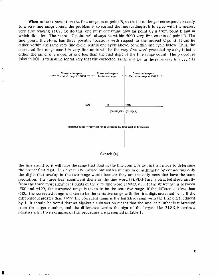
When noise is present on the fine range, as at point B, so that it no longer corresponds exactly to a very fine range count, the problem is to correct the fine reading at B to agree with the nearest very fine reading at C2. To do this, one must determine how far point C2 is from point B and in which direction. The nearest Cpoint will always be within 5000 very fine counts of point B. The fine point, therefore, has three possible locations with respect to the nearest Cpoint. It can lie either within the same very fine cycle, within one cycle above, or within one cycle below. Thus, the corrected fine range count in very fine units will be the very fine word preceded by a digit that is either the same, one more, or one less than the first digit of the fine range count. The procedure (sketch (a)) is to assume tentatively that the corrected range will lie in the same very fine cycle as
Tentative range = very fine range preceded by first digit of fine range
Sketch (a)
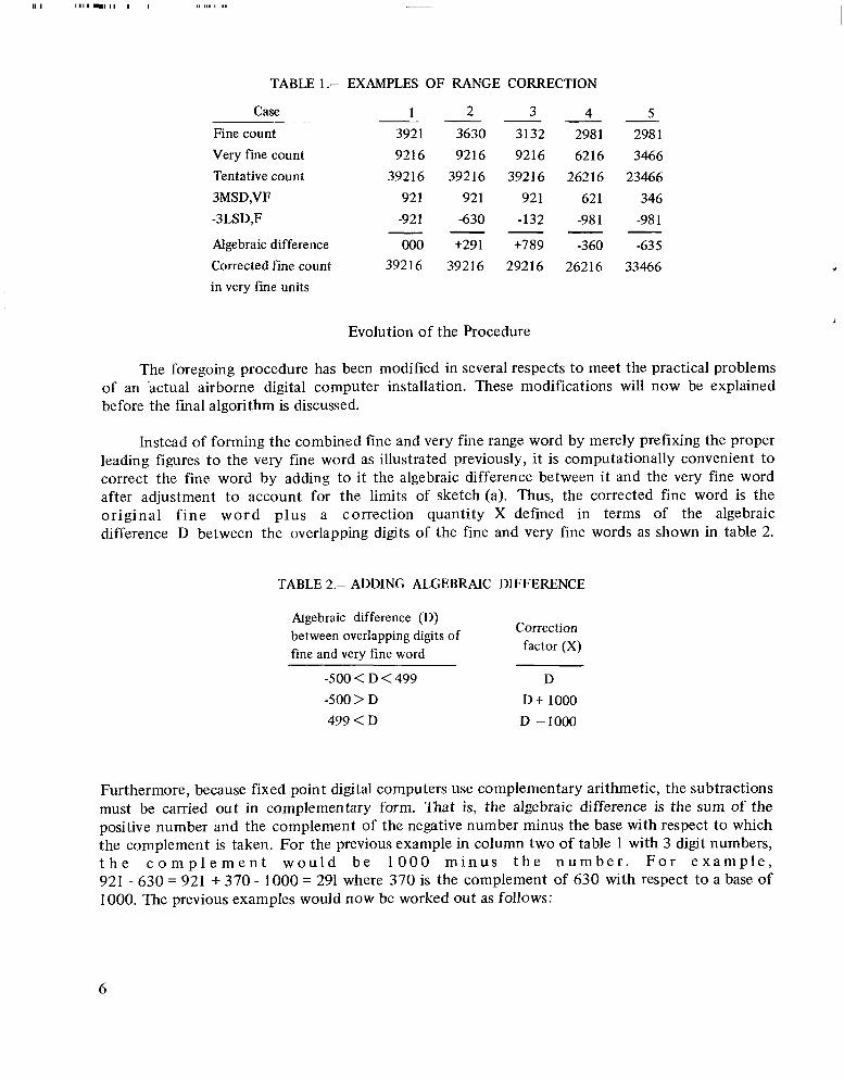
the fine count so it will have the same first digit as the fine count. A test is then made to determine the proper first digit. This test can be carried out with a minimum of arithmetic by considering only the digits that overlap in the two range words because they are the only ones that have the same resolution. The three least significant digits of the fine word ( 3LSD,F) are subtracted algebraically from the three most significant digits of the very fine word (3MSD,VF). If the difference is between -500 and t499, the corrected range is taken to be the tentative range. If the difference is less than -500, the corrected range is taken to be the tentative range with the first digit increased by 1. If the difference is greater than +499, the corrected range is the tentative range with the first digit reduced by 1. It should be noted that an algebraic subtraction means that the smaller number is subtracted from the larger number, and the difference carries the sign of the larger. The 3LSD,F carries a negative sign. Five examples of this procedure are presented in table 1.
5
- - - -
- - - -
I1 I 11111111111 I I 1 , 1 1 1 1 I.
TABLE 1.-
Case
Fine count Very fine count Tentative count 3MSD,VF -3LSD,F
Algebraic difference Corrected fine count in very fine units
EXAMPLES OF RANGE CORRECTION
1 2 3 4 3921 3630 3132 2981 9216 9216 9216 6216
39216 39216 39216 26216 92 1 92 1 92 1 62 1 -921 -630 -132 -981
000 +291 +789 -360 39216 39216 29216 26216
Evolution of the Procedure
5 298 1 3466
23466 346
-981--635
33466
The foregoing procedure has been modified in several respects to meet the practical problems of an Bctual airbome digital computer installation. These modifications will now be explained before the final algorithm is discussed.
Instead of forming the combined fine and very fine range word by merely prefixing the proper leading figures to the very fine word as illustrated previously, i t is computationally convenient to correct the fine word by adding to it the algebraic difference between it and the very fine word after adjustment t o account for the limits of sketch(a). Thus, the corrected fine word is the original f i ne w o r d plus a correction quantity X defined in terms of the algebraic difference D between the overlapping digits of the fine and very fine words as shown in table 2.
TABLE 2.- ADDING ALGEBRAIC DIFFERENCE
kgebraic difference (D)between overlapping digits of Correction
fine and very fine word factor (X)
-500 < D <499 D -500> D D t 1000 499 <D D -1000
Furthermore, because fixed point digital computers use complementary arithmetic, the subtractions must be carried out in complementary form. That is, the algebraic difference is the sum of the positive number and the complement of the negative number minus the base with respect to which the complement is taken. For the previous example in column two of table 1 with 3 digit numbers, t h e c o m p l e m e n t w o u l d b e 1 0 0 0 m i n u s t h e n u m b e r . F o r e x a m p l e , 921 - 630 = 921 + 370 - 1000 = 291 where 370 is the complement of 630 with respect to a base of 1000. The previous examples would now be worked out as follows:
6
- -
- -
- -
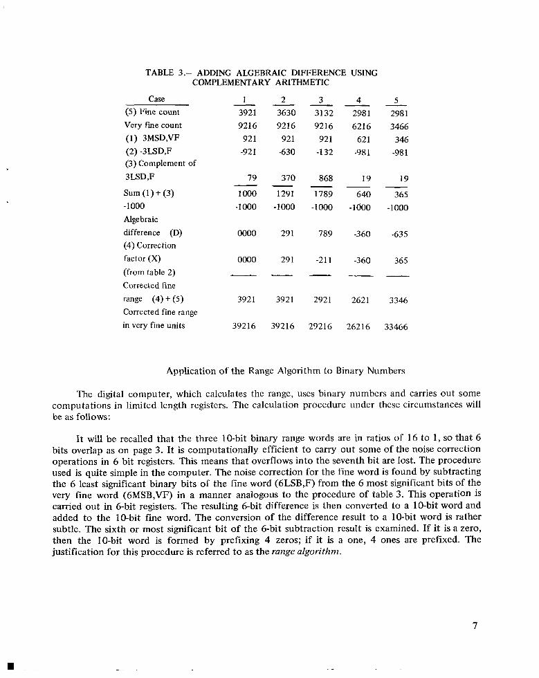
TABLE 3 .- ADDING ALGEBRAIC DIFFERENCE USING COMPLEMENTARY ARITHMETIC
- -(5) Fine count 3921 3630 3132 2981 Very fine count 921 6 9216 9216 6216 (1) 3MSD,VF 92 1 921 921 621 (2) -3LSD,F -921 -630 -132 -981 (3) Complement of 3LSD,F 79- 370- 868 19 Sum (1) + (3) 1000 1291 1789 640 -1 000 -1000 -1000 -1000 -1000 Algebraic difference (D) 0000 29 1 789 -360 (4) Correction factor (X) 0000 29 1 -21 1 -360 (from table 2)
Case 1 2 3 4
Corrected fine range (4) + (5) 3921 3921 2921 2621 Corrected fine range in very fine units 392 16 39216 29216 26216
-5 298 1 3466
346 -981
19
365 -1000
-635
36 5
-
3346
33466
Application of the Range Algorithm to Binary Numbers
The digital computer, which calculates the range, uses binary numbers and carries out some computations in limited length registers. The calculation procedure under these circumstances will be as follows:
It will be recalled that the three 10-bit binary range words are in ratios of 16 to 1, so that 6 bits overlap as on page 3. It is computationally efficient to carry out some of the noise correction operations in 6 bit registers. This means that overflows into the seventh bit are lost. The procedure used is quite simple in the computer. The noise correction for the fine word is found by subtracting the 6 least significant binary bits of the fine word (6LSB,F) from the 6 most significant bits of the very fine word (6MSB,VF) in a manner analogous to the procedure of table 3. This operation is carried out in 6-bit registers. The resulting 6-bit difference is then converted to a 10-bit word and added to the 10-bit fine word. The conversion of the difference result to a PO-bit word is rather subtle. The sixth or most significant bit of the 6-bit subtraction result is examined. If it is a zero, then the IO-bit word is formed by prefixing 4 zeros; if it is a one, 4 ones are prefixed. The justification for this procedure is referred to as the range algorithm.
7
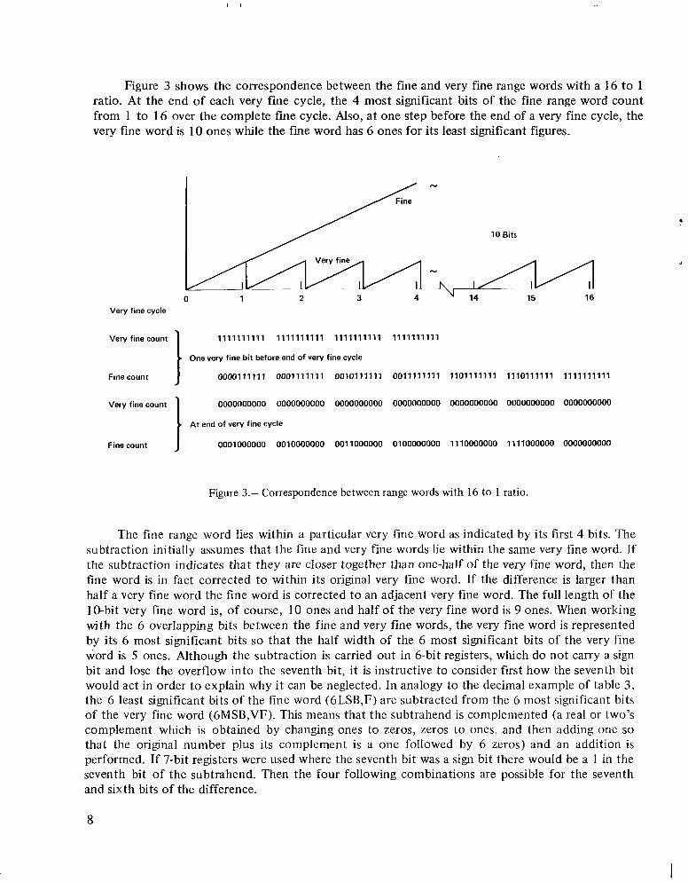
Figure 3 shows the correspondence between the fine and very fine range words with a 16 to 1 ratio. At the end of each very fine cycle, the 4 most significant bits of the fine range word count from 1 to 16 over the complete fine cycle. Also, at one step before the end of a very fine cycle, the very fine word is 10 ones while the fine word has 6 ones for its least significant figures.
N
10 Bits
0 1 2 3 4 Very fine cycle
Very fine count I 1111111111 1111111111 1111111111 1111111111
One very fine bit before end of very fine cycle
Fine count 0000111111 0001111111 0010111111 0011111111 1101111111 1110111111 1111111111
Very fine count I 0000000000 0000000000 0000000000 0000000000 0000000000 0000000000 0000000000
At end of very fine cycle
Fine count 0001000000 0010000000 0011000000 0100000000 1110000000 1111000000 0000000000
Figure 3.- Correspondence between range words with 16 to 1 ratio.
The fine range word lies within a particular very fine word as indicated by its first 4 bits. The subtraction initially assumes that the fine and very fine words lie within the same very fine word. If the subtraction indicates that they are closer together than one-half of the very fine word, then the fine word is in fact corrected to within its original very fine word. If the difference is larger than half a very fine word the fine word is corrected to an adjacent very fine word. The full length of the 1@bit very fine word is, of course, 10 ones and half of the very fine word is 9 ones. When working with the 6 overlapping bits between the fine and very fine words, the very fine word is represented by its 6 most significant bits so that the half width of the 6 most significant bits of the very fine word is 5 ones. Although the subtraction is carried out in 6-bit registers, which do not carry a sign bit and lose the overflow into the seventh bit, it is instructive to consider first how the seventh bit would act in order to explain why it can be neglected. In analogy to the decimal example of table 3, the 6 least significant bits of the fine word (6LSB,F) are subtracted from the 6 most significant bits of the very fine word (6MSB,VF). This means that the subtrahend is complemented (a real or two’s complement which is obtained by changing ones to zeros, zeros to ones, and then adding one so that the original number plus its complement is a one followed by 6 zeros) and an addition is performed. If 7-bit registers were used where the seventh bit was a sign bit there would be a I in the seventh bit of the subtrahend. Then the four following combinations are possible for the seventh and sixth bits of the difference.
8
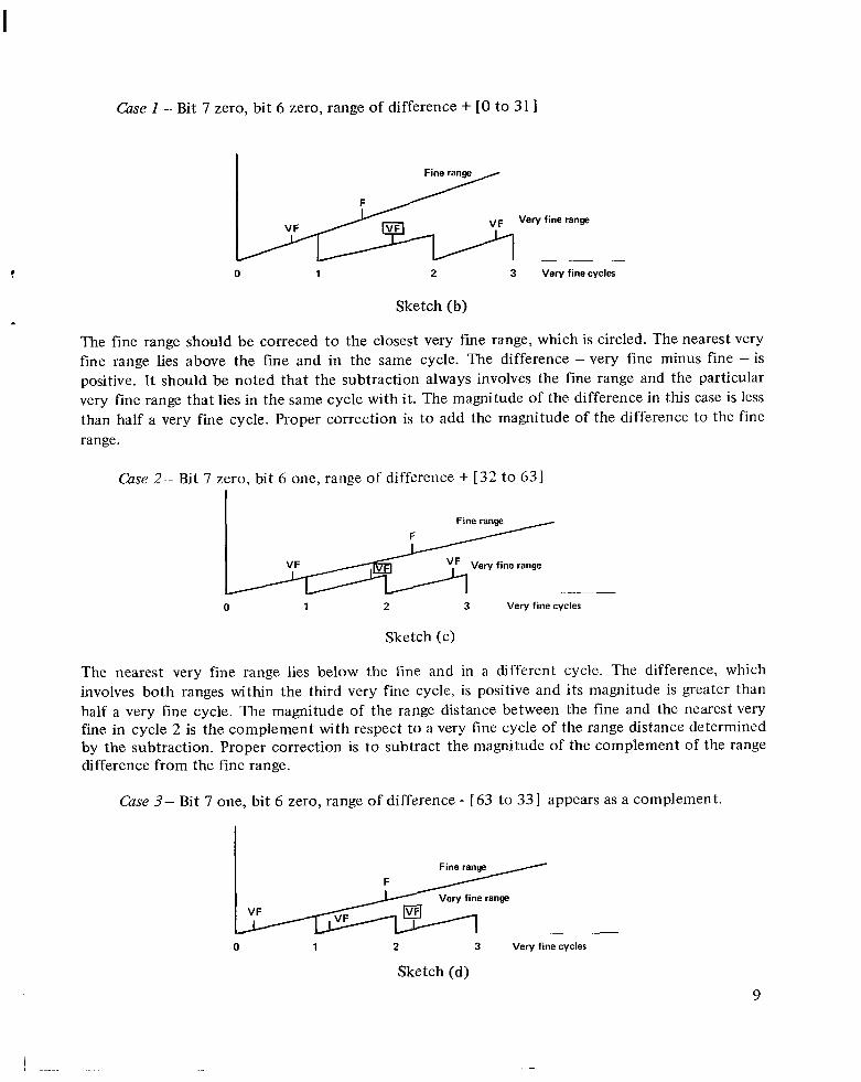
Case I - Bit 7 zero, bit 6 zero, range of difference + [O to 31 I
*
vF Very fine range
0 1 2 3 Very fine cycles
Sketch (b)
The fine range should be correced to the closest very fine range, which is circled. The nearest very fine range lies above the fine and in the same cycle. The difference - very fine minus fine - is positive. It should be noted that the subtraction always involves the fine range and the particular very fine range that lies in the same cycle with it. The magnitude of the difference in this case is less than half a very fine cycle. Proper correction is t o add the magnitude of the difference to the fine range.
Case 2- Bit 7 zero, bit 6 one, range of difference + [32 to 631
Fine range
VF Very fine range
0 1 2 3 Very fine cycles
Sketch (c)
The nearest very fine range lies below the fine and in a different cycle. The difference, which involves both ranges within the third very fine cycle, is positive and its magnitude is greater than half a very fine cycle. The magnitude of the range distance between the fine and the nearest very fine in cycle 2 is the complement with respect to a very fine cycle of the range distance determined by the subtraction. Proper correction is to subtract the magnitude of the complement of the range difference from the fine range.
Case 3- Bit 7 one, bit 6 zero, range of difference - [ 63 to 33I appears as a complement.
I Very fine range-
0 1 2 3 Very fine cycles
Sketch (d)
9

I I 1 1 1 1 1 1
The nearest very fine range lies above and in a different cycle from the fine range. The difference is negative because the very fine in the same cycle (2) with the fine lies below it. The magnitude of the difference is greater than half a very fine cycle. Proper correction is to add the magnitude of.the complement of the range difference to the fine range.
Cizse 4- Bit 7 one, bit 6 one, range of difference - [ 32 to 1] appears as a complement.
Fine range
Very fine range
0 1 2 3 Very fine cycles
Sketch (e)
The nearest very fine lies below and in the same cycle with the fine range. The difference is negative with a magnitude less than half a very fine cycle. Proper correction is t o subtract the magnitude of the difference from the fine word.
Now that all possible cases for the subtraction result have been examined, it will be shown that the same computer algorithm applies in each case. This algorithm, as stated previously, involves the examination of the sixth bit of the subtraction result, and the construction of a 10-bit word by prefixing either 4ones or 4 zeros, depending on whether the sixth bit is a one or a zero.
The cases for various combinations of ones and zeros in the sixth and seventh bit of the subtraction result will be discussed using the numerical examples with binary arithmetic and 7-bit registers where the seventh bit is a sign bit. It will be shown that the seventh bit may be disregarded as in the actual airborne computer computations that use 6-bit registers since the algorithm properly accounts for all cases by examining only the sixth bit.
Case 1 . Difference result has seventh bit zero and sixth bit zero (sketch (b)). Fine word is 00010101 10. First 4 bits indicate a location within the second cycle of the very fine word, and the last 6 bits indicate a location of 22 out of a possible 64 parts into the second cycle. Very fine word is 1011 1 Ixxxx. The last 4 bits are indicated by x since they are are not part of the overlap. The first 6 bits indicate a location of 47 parts out of a possible 64 in the cycle, where the parts are the same size as the fine word parts. The corrected location of the fine word should obviously be at 47 bits into the second cycle, or 0001 10111 1. The algorithm gives this result.
10
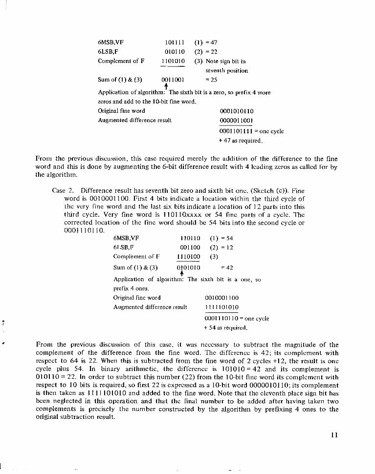
6MSB,VF 101111 (1) = 4 7 6LSB,F 010110 (2) = 22 Complement of F 1101010 (3) Note sign bit in
seventh position Sum of (1) & (3) 0011001 = 25
fApplication of algorithm: The sixth bit is a zero, so prefix 4 more zeros and add to the 10-bit fine word. Original fine word 0001010110 Augmented difference result 0000011001
0001101111 = one cycle + 47 as required.
From the previous discussion, this case required merely the addition of the difference to the fine word and this is done by augmenting the 6-bit difference result with 4 leading zeros as called for by the algorithm.
Case 2. Difference result has seventh bit zero and sixth bit one. (Sketch (c)). Fine word is 0010001 100. First 4 bits indicate a location within the third cycle of the very fine word and the last six bits indicate a location of 12 parts into this third cycle. Very tine word is 1101lOxxxx or 54 fine parts of a cycle. The corrected location of the fine word should be 54 bits into the second cycle or 0001 110110.
6MSB,VF 110110 (1) = 54 6LSB,F 001100 (2) = 12 Complement of F 1110100 (3)
Sum of (1) & (3) 0101010 = 42 4
Application of algorithm: The sixth bit is a one, so prefix 4 ones. Original fine word 0010001100
Augmented difference result 1111101010
0001110110 = one cycle 1 + 54 as required.
8 From the previous discussion of this case, it was necessary to subtract the magnitude of the complement of the difference from the fine word. The difference is 42; its complement with respect to 64 is 22. When this is subtracted from the fine word of 2 cycles +12, the result is one cycle plus 54. In binary arithmetic, the difference is 101010= 42 and its complement is 0101 10 = 22. In order to subtract this number (22) from the IO-bit fine word its complement with respect to 10 bits is required, so first 22 is expressed as a 10-bit word 0000010110; its complement is then taken as 1 1 11 101010 and added to the fine word. Note that the eleventh place sign bit has been neglected in this operation and that the final number to be added after having taken two complements is precisely the number constructed by the algorithm by prefixing 4 ones to the original subtraction result.
11
I
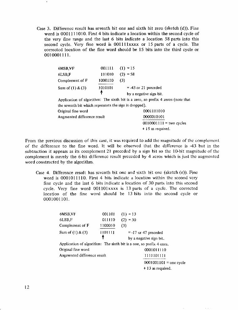
Case 3. Difference result has seventh bit one and sixth bit zero (sketch (d)). Fine word is 0001 111010. First 4 bits indicate a location within the second cycle of the very fine range and the last 6 bits indicate a location 58 parts into this second cycle. Very fine word is 001 11lxxxx or 15 parts of a cycle. The corrected location of the fine word should be 15 bits into the third cycle or 0010001111.
6MSB,VF 001111 (1) = 1 5 6LSB,F 111010 (2) = 58 Complement of F 1000110 (3)
Sum of (1) & (3) 1010101 = -43 or 21 preceded .t. by a negative sign bit.
Application of algorithm: The sixth bit is a zero, so prefix 4 zeros (note that the seventh bit which represents the sign is dropped). Original fine word 0001111010 Augmented difference result 0000010101
0010001 111 = two cycles + 15 as required.
From the previous discussion of this case, it was required to add the magnitude of the complement of the difference t o the fine word. It will be observed that the difference is -43 but in the subtraction it appears as its complement 21 preceded by a sign bit so the 10-bit magnitude of the complement is merely the 6-bit difference result preceded by 4 zeros which is just the augmented word constructed by the algorithm.
Case 4. Difference result has seventh bit one and sixth bit one (sketch (e)). Fine word is 000101 I 110. First 4 bits indicate a location within the second very fine cycle and the last 6 bits indicate a location of 30 parts into this second cycle. Very fine word 001 lOlxxxx is 13 parts of a cycle. The corrected location of the fine word should be 13 bits into the second cycle or 0001001 101.
6MSB,VF 001101 (1) = 13 6LSB,F 011110 (2) = 3 0 Complement of F 1100010 (3)
Sum of (1) & (3) 11011 11 = -17 or 47 precededf by a negative sign bit.
Application of algorithm: The sixth bit is a one, so prefK 4 ones. Original fine word 000101 11 10 Augmented difference result 1111101111
0001001 101 = one cycle + 13 as required.
12
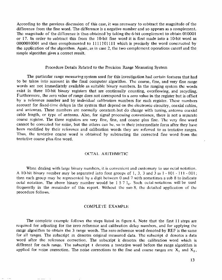
According to the previous discussion of this case, it was necessary to subtract the magnitude of the difference from the fine word. The difference is a negative number and so appears as a complement. The magnitude of the difference is thus obtained by taking the 6-bit complement to obtain 010001 or 17. In order to subtract this from the 10-bit fine word i t is first made into a 10-bit word as 0000010001 and then complemented to 11 1110111 1 which is precisely the word constructed by the application of the algorithm. Again, as in case 2, the two complement operations cancel and the simple algorithm gives a correct result.
Procedure Details Related to the Precision Range Measuring System
The particular range measuring system used for this investigation had certain features that had to be taken into account in the final computer algorithm. The coarse, fine, and very fine range words are not immediately available as suitable binary numbers. In the ranging system the words exist in three 10-bit binary registers that are continually counting, overflowing, and recycling. Furthermore, the zero value of range does not correspond to a zero value in the register but is offset by a reference number and by individual calibration numbers for each register. These numbers account for fixed-time delays in the system that depend on the electronic circuitry, coaxial cables, and antennas. These numbers are normally constant.but do change with tuning, antenna coaxial cable length, or type of antenna. Also, for signal processing convenience, there is not a separate coarse register. The three registers are very fme, fine, and coarse plus fine. The very fine word cannot be corrected for noise, but the others can be, so in their intermediate form after they have been modified by their reference and calibration words they are referred to as tentative ranges. Thus, the tentative coarse word is obtained by subtracting the corrected fine word from the tentative coarse plus fine word.
OCTAL ARITHMETIC
When dealing with large binary numbers, it is convenient and customary to use octal notation. A 10-bit binary number may be separated into four groups of 1, 3 , 3 and 3 as 1 - 101 - 1 1 1 - 001 ; then each group may be represented by a digit between 0 and 7 with sometimes a sub 8 to indicate octal notation. The above binary number would be 1 5 7 1,. Such octal notations will be used frequently in the remainder of this report. Without the SUD 8, the detailed application of the procedure follows.
COMPLETE EXAMPLE
The complete example follows the steps listed in figure 4. Note that the first 1 1 steps are required for adjusting for the zero reference and calibration delay numbers, and for applying the range algorithm to obtain the 3 range words. The zero reference word denoted by REF is the same for all ranges. The subscript m denotes original measured data. The subscript d denotes a data word after the reference correction. The subscript k denotes the calibration word which is different for each range. The subscript t denotes a tentative word before the range algorithm is applied for noise correction. The noise corrections to the fine and coarse ranges are X, and X,,
13
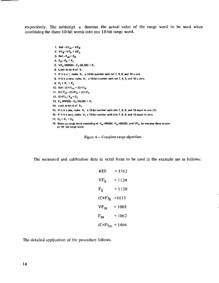
respectively. The subscript a denotes the actual value of the range word to be used when combining the three 1@bit words into one 18-bit range word.
1. Ref-VF,=VFd
2. vFd-vFk=vFa
3. Ref -Fm = Fd
4. Fd- Fk = Ft
5. VFa (6MSB)-Ft (6LSB) = XI
6. Lookat b i t6of XI
7. If it is a 1, make XI a 10-bitnumber with bit 7, 8, 9, and 10 a one.
8. I f it is a zero, make XI a 10-bitnumber with bit 7, 8,9, and 10 a zero.
9. Ft + XI = Fa
10. Ref -(C+F), (c+F)d
11. (c+F)d-(c+F)k = (C+F)t
12. (C+F)t- Fa= Ct
13. Fa (6MSB)-Ct (6LSB) = X,
14. Look a t bit 6 of X,.
15. If it is a one, make X, a 10-bitnumber with bits 7, 8, 9, and 10 equal to one (1).
16. If it is a zero, make X, a 10-bitnumber with bits 7, 8, 9, and 10 equal to zero.
17. Ct+X, =Ca
18. Make up range word consisting of Ca (4MSB), Fa (4MSB).and VFa by merging these to give an 18-bit range word.
Figure 4.- Complete range algorithm.
The measured and calibration data in octal form to be used in the example are as follows:
REF
VFk
Fk
(C+F)k
VFm
Fm
(C+F),
The detailed application of the procedure follows.
= 1762
= 1124
= 1120
=1613
= 1003
= 1062
= 1466
14
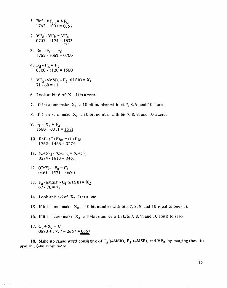
1. Ref - VFm = VFd 1762 - 1003 = 0757
2. VFd - VFk = VFa 0757 - 1124= 1633--
3. Ref - Fm = Fd 1762 - 1062 = 0700
4. Fd - F k = Ft 0700- 1120= 1560
5. VFa (6MSB) - Ft (6LSB) = XI 71 - 6 0 = 11
6. Look at bit 6 of X, . It is a zero.
7. If it is a one make X, a 10-bit number with bit 7, 8, 9, and 10 a one.
8. If it is a zero make X1 a 10-bit number with bit 7, 8, 9, and 10 a zero.
9. Ft + X1 = Fa 1560 +0011 =m-
10. Ref - (C+F)m = (C+F)d 1762- 1 4 6 6 ~ 0 2 7 4
11. (C+F)d - (C+F)k = (C+F)t 0274- 1 6 1 3 4 4 6 1
12. (C+F)t - Fa = Ct 0461 - 1571 = 0670
13. Fa (6MSB) - Ct (6LSB) = X2 67 - 70 = 77
14. Look at bit 6 of X2 . It is a one.
15. If it is a one make X, a 10-bit number with bits 7, 8, 9, and 10 equal to one (1).
16. If it is a zero make X, a 1O-bit number with bits 7, 8, 9, and 10 equal to zero.
17. Ct +X, = C, 0 6 7 0 + 1 7 7 7 = 2 6 6 7 = 0 6 6 7
18. Make up range word consisting of Ca (4MSB), Fa (4MSB), and VFa by merging these to give an 1%bit range word.
15
The three octal words, which were underlined, are now converted to binary and placed in their proper relative locations to form the 18-bit range word shown below.
Coarse word 0110110111 Fine word 1101111001 Very fine word 1110011011
Note that all of the overlap bits are identical, which was the object of the algorithm. The final step is to merge the three words into one, which is now a trivial operation. The result is
011011011110011011
which is the final 1%bit range word. The bit weighting chart in figure 1 is used to convert the 18-bit word to 81,478.236 feet.
FLIGHT CONFIRMATION
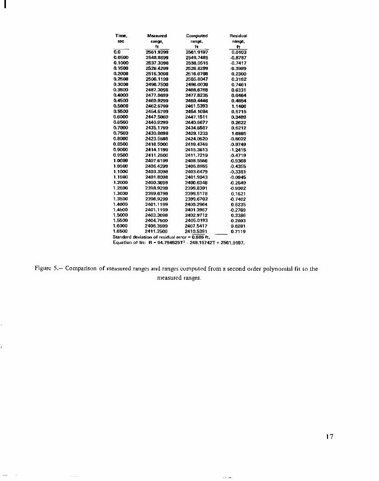
The statement has been made that the errors due to noise are small and that the coarse errors and fine errors will remain sufficiently small. It was also claimed that noise errors on the very fine word were even smaller because special steps had been taken to insure that they would be. To show that these claims were justified, a portion of a set of range measurements, selected to show the minimum range to a Lear Jet flying overhead, is shown in figure 5.
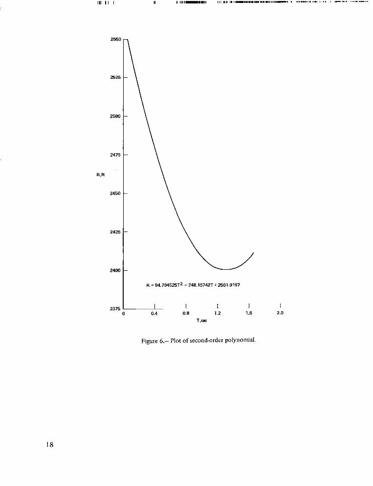
In figure 6, a second-order curve has been fitted through the range data points of figure 5 and plotted. A least-squares procedure was used to compute this curve and the residual errors from the curve to each of the data points. The standard deviation of the residual errors was found to be 0.686 foot. The largest residual was 1.6865 feet.
16
I
Time, Measured Computed Residual 5eC range. range. range.
ft h f t 0.0 2561.9299 2561.9197 0.0103 0.0500 2548.8699 2549.7485 -0.8787 0.1000 2537.3098 2538.0515 -0.7417 0.1500 2526.4299 2526.8289 -0.3989 0.2000 2516.3098 2516.0798 0.2300 0.2500 2506.1199 2505.8047 0.3152 0.3000 2496.7500 2496.0039 0.7461 0.3500 2487.3098 2486.6768 0.6331 0.4000 2477.8699 2477.8235 0.0464 0.4500 2469.9299 2469.4446 0.4854 0.5000 2462.6799 2461.5393 1.1406 0.5500 2454.6799 2454.1084 0.5715 0.6000 2447.5000 2447.1511 0.3489 0.6500 2440.9299 2440.6677 0.2622 0.7000 2435.1799 2434.6587 0.5212 0.7500 2430.8098 2429.1233 1.6865 0.8000 2423.5598 2424.0620 -0.5022 0.8500 2418.5000 2419.4749 -0.9749 0.9000 2414.1 199 2415.3613 -1.2415 0.9500 2411.2500 2411.7219 -0.4719 1.moo 2407.6199 2408.5566 -0.9368 1.0500 2405.4299 2405.8655 -0.4355 1.1000 2403.3098 2403.6479 -0.3381 1.1500 2401.8098 2401.9043 -0.0945 1.2000 2400.3699 2400.6348 -0.2649 1.2500 2398.9299 2399.8391 -0.9092 1.3000 2399.6799 2399.5178 0.1621 1.3500 2398.9299 2399.6702 -0.7402 1.4000 2401.1 199 2400.2964 0.8235 1.4500 2401.1199 2401.3967 -0.2769 1.5000 2403.3098 2402.9712 0.3386 1.5500 2404.7500 2405.0193 -0.2693 1.6000 2408.3699 2407.5417 0.8281 1.6500 2411.2500 2410.5381 0.7119 Standard deviation of residual error = 0.686 ft. Equation of fit: R = 94.794525T2 - 248.15742T + 2561.9197.
Figure 5.- Comparison of measured ranges and ranges computed from a second order polynomial fit to the measured ranges.
17
111 I I I
2550
2525
2500
2475
2425
2400
R = 94.794525T2 -248.15742T+2561.9197
2375 1 I 0 0.4 0.8 1.2 1.6 2.0
T,sec
Figure 6.- Plot of second-orderpolynomial.
18
CONCLUDING REMARKS
The range resolution algorithm devised is capable of combining three ambiguous 10-bit range words into one 1&bit range word. Using this algorithm a range measuring system can provide very accurate ranges to a digital computer capable of operating on an aircraft.
Results were shown in which the range to aircraft flying overhead was measured to an accuracy whose standard deviation was 0.686 foot.
Considerable experience has been gained with this system on many flights over Moffett Field, California, which contains three very large dirigible hangars and many other buildings. Since no detrimental effects due to multipath signals have been encountered to date, i t must be concluded that ranges measured to a rapidly moving aircraft do not suffer noticeably from multipath signals.
Ames Research Center National Aeronautics and Space Administration
Moffett Field, Calif., 94035, Aug. 13, 1970
REFERENCE
1. Robinson, Gilbert G.; and Johnson, Norman S. : Subsystem Requirements for an Airborne Laboratory to Study Zero-Zero Landing Systems. AGARD Rep. 488, Advisory Group for Aeronautical Research and Development, North Atlantic Treaty Organization, Oct. 1964.
NASA-langley, 1911 - 2 A-2842 19
Y
NATIONAL AND SPACE ADMINISTRATAERONAUTICS ION
WASHINGTON,D. C. 20546 ~~
OFFICIAL BUSINESS FIRST CLASS MAIL
POSTAGE A N D FEES PAID NATIONAL AERONAUTICS A N D
SPACE ADMINISTRATION
0 8 U 001 27 51 30s 71043 00903 A I R F O R C E WEAPCNS LABORATORY /WLOL/ K I R T L A N O A F B , N E h M E X I C O 87117
A T T E o L O U BOWPAN1 CHIEF,TECHo L I B R A R Y
If Undeliverable (Section 158 Postal Manual) Do Not Return
“The aeronazitical and space activities of the United States shall be conducted so as t o contribute . . . t o the expansion of human knowledge of phenomena in the atmosphere and space. T h e Administration shall provide for the widest practicable and appropriate dissemination o f .information concerning its actiuities and the results thereof.”
-NATIONALAERONAUTICSAND SPACE ACT OF 1958
NASA SCIENTIFIC AND TECHNICAL PUBLICATIONS
TECHNICAL REPORTS: Scientific and technical information considered important, complete, and a lasting contribution to existing knowledge.
TECHNICAL NOTES: Information less broad in scope but nevertheless of importance as a contribution to existing knowledge.
TECHNICAL MEMORANDUMS: Information receiving limited distribution because of preliminary data, security classification, or other reasons.
CONTRACTOR REPORTS: Scientific and technical information generated under a NASA contract or grant and considered an important contribution to existing knowledge.
TECHNICAL TRANSLATIONS: Information published in a foreign language considered to merit NASA distribution in English.
SPECIAL PUBLICATIONS: Information derived from or of value to NASA activities. Publications include conference proceedings, monographs, data compilations, handbooks, sourcebooks, and special bibliographies.
TECHNOLOGY UTILIZATION PUBLICATIONS: Information on technology used by NASA that may be of particular interest in commercial and other non-aerospace applications. Publications include Tech Briefs, Technology Utilization Reports and Technology Surveys.
Details on the availability of these publications may be obtained from:
SC IENT IFIC AND TECHN I CA L I NFORMATION 0FFICE
NATIONA L AERON AUT1C S AND SPACE ADMINISTRATION Washington, D.C. PO546