Embed Size (px)
Citation preview


Fluid Power Electrical Automation
Hydraulics
Teachware
Didactic Support
Mechanical Pneumatics
Fluid Power Component Sizing
Electrical Component Sizing
Bill of Material & Report
Manufacturers' Catalogues
Catalogue Manager
Control Panels & 2D-3D HMI
SFC Compilers & Export to Siemens™ and XML format(Automation Studio PLC™)
Sequential Function Chart (SFC/GRAFCET)
Digital Electronics
Electrical Controls
APIs / Script Language
Electrotechnical One-line
OPC Client & OPC Server (CAN Bus)
PLC Ladder Logic Allen Bradley™ Siemens™ & IEC 1131
Electrotechnical
Multi-User
Mining
Construction
Agricultural
Oil & Gas
Forestry
Aerospace
Subsea
Energy
Mechatronics
Industrial Automation
Electrical Engineering
Heavy Duty Mechanics
Mechanical Engineering
Electromechanical Technologies
Industrial Maintenance
Mechanical Design
MACHINE
DOCUMENTATION SIM
ULAT
IO
N &
ANIM
ATION
TRADE ORIENTED SYSTEM DESIGN
2
Once again, Automation Studio™ pushes the boundaries of innovation and widens the gap with any other system design software available in the industry. Automation Studio™ is already known for being the unique design & simulation solution covering all project/machine technologies including hydraulics, pneumatics, electrical, controls, HMI, and communications. It is very easy to combine these various technologies in order to design, document and simulate complete systems.
Automation Studio™ is intended to be used by engineers and specialists in:
A Complete Project/Product Lifecycle Solution….
Overview P2Fluid Power P6HMI & Control Panels P11Electrical P12Automation P18Catalogues P22Applications P24
INDEX

3
Automation Studio™ offers a unique combination of user-friendly system design features, advanced engineering capabilities, dynamic and realistic simulation, comprehensive animation features, and flexible documentation functionalities in one common environment. It brings a new dimension that allows manufacturers, OEMs, and end-users to optimize system implementation, deployment, and maintenance.
Whether you are involved in the design, training, sales, production, or maintenance, Automation Studio™ can help your organization by improving quality, speeding up workflow, and boosting productivity while simultaneously reducing costs and enhancing all aspects of project communication.
Automation Studio™ offers a wide array of innovations allowing organizations to release synergy amongst team projects and optimizing every step of a product/project life cycle. The result: increased productivity and reduced product time-to-market
…To Optimize Your Entire Workflow
Flui
d Po
wer
HMI &
Con
trol
Pan
els
Elec
tric
alAu
tom
atio
nCa
talo
gues
Appl
icat
ions
Over
view

4
Complete Set of Libraries for Fast & Accurate DesignAutomation Studio™ libraries offer thousands of generic components structured by categories in a friendly manner, compliant with several international standards: ISO, DIN, JIC, IEC, and NEMA.
Configurable Displayed InformationDetailed information can be displayed directly on the diagram or in tooltips appearing when hovering over the corresponding components on the screen.
Dynamic Measuring InstrumentsThese virtual instruments can be inserted in a circuit during simulation in order to monitor various parameters such as pressure, flow, voltage, speed and more.
Dynamic and Realistic Simulation in Full ColourDuring simulation, components become animated and lines are colour-coded according to their states. The simulation pace can also be adjusted with functions such as Normal, Step by Step, Slow Motion, and Pause.
Bill of MaterialWith just one click you can quickly assign data to all components of a project to generate bills of materials, requests for quotes, budgetary estimates and more.
Component SizingThe Component Sizing Module provides valuable and flexible computer-aided sizing calculations for various components.
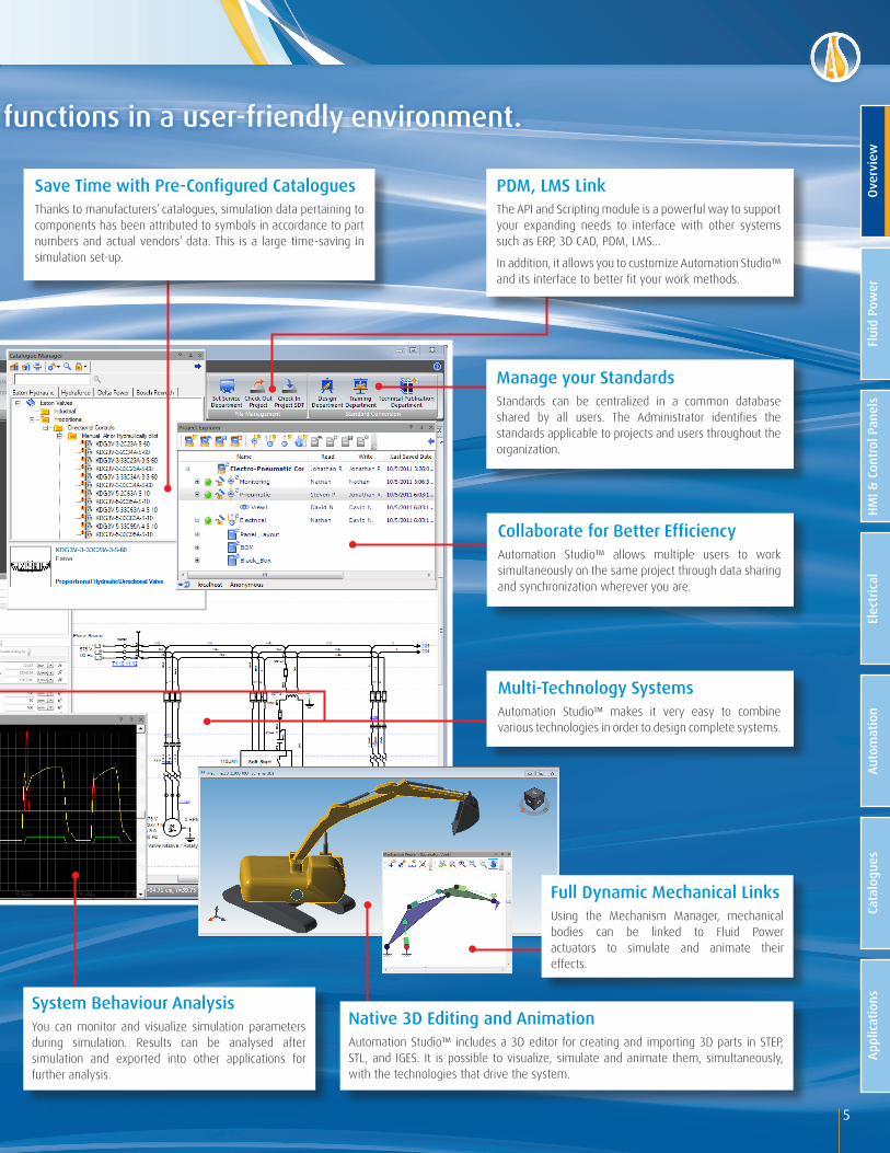
Automation Studio™ offers powerful design functions in a user-friendly environment.
Overview
5
Collaborate for Better EfficiencyAutomation Studio™ allows multiple users to work simultaneously on the same project through data sharing and synchronization wherever you are.
System Behaviour AnalysisYou can monitor and visualize simulation parameters during simulation. Results can be analysed after simulation and exported into other applications for further analysis.
Manage your StandardsStandards can be centralized in a common database shared by all users. The Administrator identifies the standards applicable to projects and users throughout the organization.
Automation Studio™ offers powerful design functions in a user-friendly environment.
Multi-Technology SystemsAutomation Studio™ makes it very easy to combine various technologies in order to design complete systems.
Full Dynamic Mechanical LinksUsing the Mechanism Manager, mechanical bodies can be linked to Fluid Power actuators to simulate and animate their effects.
Native 3D Editing and AnimationAutomation Studio™ includes a 3D editor for creating and importing 3D parts in STEP, STL, and IGES. It is possible to visualize, simulate and animate them, simultaneously, with the technologies that drive the system.
PDM, LMS Link The API and Scripting module is a powerful way to support your expanding needs to interface with other systems such as ERP, 3D CAD, PDM, LMS…
In addition, it allows you to customize Automation Studio™ and its interface to better fit your work methods.
Save Time with Pre-Configured Catalogues Thanks to manufacturers’ catalogues, simulation data pertaining to components has been attributed to symbols in accordance to part numbers and actual vendors’ data. This is a large time-saving in simulation set-up.
Flui
d Po
wer
HMI &
Con
trol
Pan
els
Elec
tric
alAu
tom
atio
nCa
talo
gues
Appl
icat
ions
Over
view
• Customize your projects and diagrams according to required standards• Accurate and realistic simulation• Component sizing• Wide selection of preconfigured manufacturers' products• Full range of analysis and validation tools• Component failure management
6
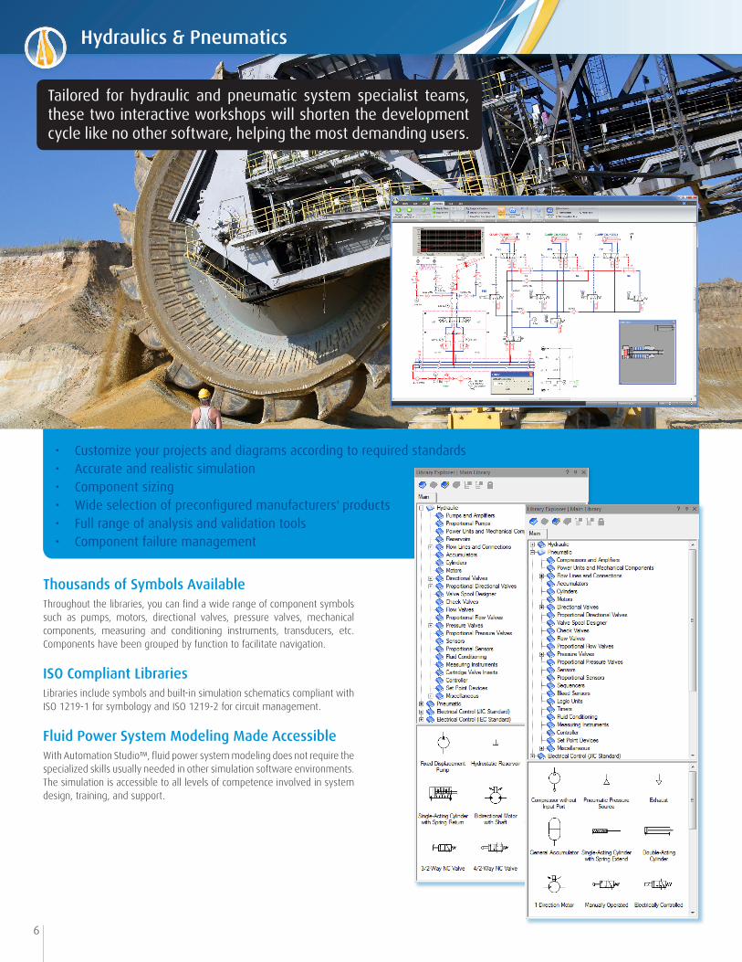
Thousands of Symbols Available Throughout the libraries, you can find a wide range of component symbols such as pumps, motors, directional valves, pressure valves, mechanical components, measuring and conditioning instruments, transducers, etc. Components have been grouped by function to facilitate navigation.
ISO Compliant LibrariesLibraries include symbols and built-in simulation schematics compliant with ISO 1219-1 for symbology and ISO 1219-2 for circuit management.
Fluid Power System Modeling Made AccessibleWith Automation Studio™, fluid power system modeling does not require the specialized skills usually needed in other simulation software environments. The simulation is accessible to all levels of competence involved in system design, training, and support .
Tailored for hydraulic and pneumatic system specialist teams, these two interactive workshops will shorten the development cycle like no other software, helping the most demanding users.
Hydraulics & Pneumatics

7
Valve ConfiguratorsAutomation Studio™ provides configuration tools that allow you to create your own symbols and simulation models. Several user-friendly interfaces are available to help you design valves, reservoirs, gearbox, etc., giving you complete freedom and autonomy.
Actuators and Pumps ConfiguratorsConfiguration tools are also available for actuators and pumps. Actuators can be easily reconfigured to reach your symbol requirement while the pump builders offer a large range of preconfigured manufacturer options.
Custom ComponentThe Custom Component allows you to create your own animated symbols, by assigning them the behaviour of any circuit combining electrical, hydraulic or pneumatic technologies, with the possibility to add a logic defined in a GRAFCET/SFC.
Hydraulics & Pneumatics
Flui
d Po
wer
HMI &
Con
trol
Pan
els
Elec
tric
alAu
tom
atio
nCa
talo
gues
Appl
icat
ions
Over
view

8
Mechanical LinksThe Mechanism Manager allows you to analyse the effects a cylinder's independent displacement will have on the dynamics of a system under study. Mechanisms can easily be created and complex dynamic behaviour analysis can be derived for multi-body systems.
Spool Position DesignerAutomation Studio™ offers thousands of pre-configured spools within the valve builder. In case you do not find the needed spool symbol, the Spool Position Designer allows you to easily build and store it in your Custom Spool database for future use.
The Spool Position Designer incorporates all the schematic tools required to create the spool position circuit of the inner function of any directional valve. The spool position may incorporate components such as flow control, pressure control, lines, orifices, restrictions, etc.
Actuator Load & Force Profile Configuration All forces and loads applied to cylinders and motors can be determined as a function of actuator's position or by linking to another component’s variable. You can therefore enter load scenarios in accordance with equipment use and geometry in order to reflect its real behaviour. The emulation of complex mechanical systems and unforeseen events becomes easily accessible.
Diagnostic ToolsAutomation Studio™ provides extensive diagnostic tools allowing for detection of inconsistencies or errors such as free connectors, redundant or overlapping lines, non-compliance with ISO standards, etc.
Hydraulics & Pneumatics

9
Dynamic Parameter Tuning in SimulationAt any time during simulation, you can adjust equipment parameters and manually control just about any device: set a pressure on a relief valve, operate a lever, a joystick or a valve, the choice is yours!
Choice of Simulated PhenomenaDepending on the required precision level, Automation Studio™ allows you to take into consideration various simulation phenomena involved in fluid that flows in a circuit.
Fluid and Line ConfigurationAutomation Studio™ offers a rich set of pre-configured types of fluid, hoses, and material. In the case where you do not find the needed element, you can easily define it and save it for future use. Fluid and line builder allows you to configure the lines based on circuit, installation, function, material, type, etc. Line appearance can be configured for both editing and simulation. Furthermore, during simulation, the appearance can be defined as a function of threshold levels of either flow or pressure.
• External effort on actuators can be constant, periodic, or variable
• Static and dynamic friction
• Internal and external leaks
• Volumetric, mechanical, and thermal efficiencies
• Inertia and mechanical transmission
• Valve kinematic and response time
• Dead band and hysteresis
• Flow force on valves
• Flow characteristics
• Component failure
• Specific heat coefficient
Simulation Parameters
Hydraulics & Pneumatics
Flui
d Po
wer
HMI &
Con
trol
Pan
els
Elec
tric
alAu
tom
atio
nCa
talo
gues
Appl
icat
ions
Over
view

10
• Fast and easy access to applicable formulas, equations, and parameter definitions• Intuitive calculation sheets provided for each family of components• Rapid system prototyping• Save money by eliminating oversized components• Reduce risk by avoiding undersized components that do not meet expected performances
A Multidirectional ApproachAs opposed to traditional means of solving equations where you have to select an entry point, Automation Studio™ calculation sheets allow parameter modification from any point in the circuit. This eliminates the need to proceed in a predetermined step-by-step approach. When you modify or recalculate parameters, variables are modified and can be transferred to the component assigned. In turn, the new parameters can be validated and applied to the component simulation parameters.
From Components to Systems with SimulationOnce each component has been sized, it becomes easy to establish the overall system requirements by running a simulation and establishing operating sequences. This turns Automation Studio™ into a valuable tool to quickly design workable circuits. For example, you can rapidly determine the energy consumption in your fluid power system and optimize the operating costs.
Quick Access to Equations and DefinitionsAutomation Studio™ becomes a quick reference, saving time in searching for information from data books or deriving equations. The unit systems can be defined, and results displayed in any unit system, making conversion quick and easy, especially when entering component data retrieved from various catalogues.
This module provides valuable computer-aided engineering capabilities helping you identify components expected constraints and performance characteristics.
Fluid Power and Electrical Component Sizing
11
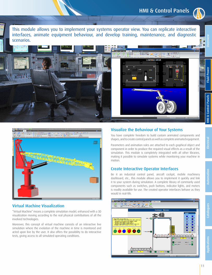
Visualize the Behaviour of Your SystemsYou have complete freedom to build custom animated components and shapes, and to create control panels as well as complete animated equipment.
Parameters and animation rules are attached to each graphical object and component in order to produce the required visual effects as a result of the simulation. This module is completely integrated with all other libraries, making it possible to simulate systems while monitoring your machine in motion.
Create Interactive Operator InterfacesBe it an industrial control panel, aircraft cockpit, mobile machinery dashboard, etc., this module allows you to implement it quickly and link it to your system during simulation. A complete library of commonly used components such as switches, push buttons, indicator lights, and meters is readily available for use. The created operator interfaces behave as they would in real-life.
Virtual Machine Visualization“Virtual Machine” means a complete simulation model, enhanced with a 3D visualization moving according to the real physical contributions of all the involved technologies.
Moreover, this concept of virtual machine consists of an interactive live simulation where the evolution of the machine in time is monitored and acted upon live by the user. It also offers the possibility to do interactive tests, giving access to all simulated operating conditions.
This module allows you to implement your systems operator view. You can replicate interactive interfaces, animate equipment behaviour, and develop training, maintenance, and diagnostic scenarios.
HMI & Control Panels
HMI &
Con
trol
Pan
els
Elec
tric
alAu
tom
atio
nCa
talo
gues
Appl
icat
ions
Over
view
Flui
d Po
wer

• Diagram representation according to your company standards • Build and simulate complete electrical systems• Full IEC and NEMA standards support• Customizable symbols• Component sizing• Full range of analysis and validation tools• Component failure management• Test and validate PLC logic sequences on a complete virtual system
12
Trade Oriented Editor This workshop offers special editing functions and features especially adapted to create electrical system documentation. Combined with the system design features, this provides a user-friendly and efficient environment for the electrical designer.
Dynamic and Realistic SimulationThe Electrical Simulator is based on established and reliable modeling techniques. During simulation, you can precisely monitor voltage, current, resistance and impedance at any point in a circuit. For example, you can validate control logic sequences, apply loads to motors and see the effects on current, speed or on other elements such as protection devices, etc.
Extensive NEMA and IEC Symbol LibrariesThe Electrical Symbol Libraries will serve the needs of the most demanding system designers. All symbols are supplied in separate libraries for each standard, in a very comprehensive way. Searching for the right symbol is fast and easy. The specialized editor also complies with the standards by differentiating power and controls components, thus making it easy to identify machine elements.
This workshop offers a user-friendly and powerful solution for electrical systems design. Thanks to the multi-document and multi-user project structure, you can quickly and effectively design small or large projects.
Electrical

13
Fully Customizable Connection DiagramsThe Connection Diagram Editor empowers you to create complete diagrams showing the connectivity between the components in your electrical schematic. When creating a connection diagram, elements are automatically matched with the corresponding components. Connec-tions and cable structure information are added and tagged with only a few clicks. Changes in the electrical schematic are automatically updated and flagged in the connection diagram.
Black Box Model Implementation for Complete AutonomyThis feature gives automation specialists the ability to design new components. If a specific symbol or a more complex function, such as controllers, is required, the Black Box component enables you to create it using buttons, digital and analog I/O, text, or HMI elements.
Cable and Wire ManagementYou can manage all spool-related data such as materials, gauges, colours, patterns, detailed representations of cables, etc. You can also create cable types by combining wires in different configurations (coaxial, twisted pairs, or shields). The wire material, gauge and length are taken into consideration to simulate wire electrical resistance giving a precise measurement of voltage drop across cables.
• Free connectors
• Free emitter/receiver
• Uniqueness of item identifier
• Components directly connected (without wire)
• Non-associated links
• Components not associated to a catalogue part
• Too many wires on component connector
• Redundant wires
• Declared failures
• All accessories with symbol
• Free accessories with symbol
• Components with locked item identifier
• Components with locked displayable number
Panel Layout DesignerTools are available to quickly implement and design entire scaled cabinets and junction boxes. Components can easily be inserted simply by dragging and dropping them into the workspace. The number of components in the library is automatically updated with every insertion of a component to reduce design errors. A rail mounting for assembly grouping as well as ducting elements for wires are made available for quick design.
Complete Connector StructureThe Connector Builder allows you to construct complex connector structures including geometrically customizable housings, modules and cavities. Any electric plug or socket can be matched to any cavity in a given connector, paving the way for harness building.
Dynamic Connector ImageThe connectivity information can be displayed for each connector cavity. A complete scaled representation of the connector, along with hyperlinks to and from the electric plugs or sockets render connections analysis and navigation between connector's cavities easy.
Diagnostic ToolsAutomation Studio™ provides extensive Diagnostic Tools allowing for the detection of inconsistencies or errors such as:
Electrical
Flui
d Po
wer
HMI &
Con
trol
Pan
els
Elec
tric
alAu
tom
atio
nCa
talo
gues
Appl
icat
ions
Over
view
14
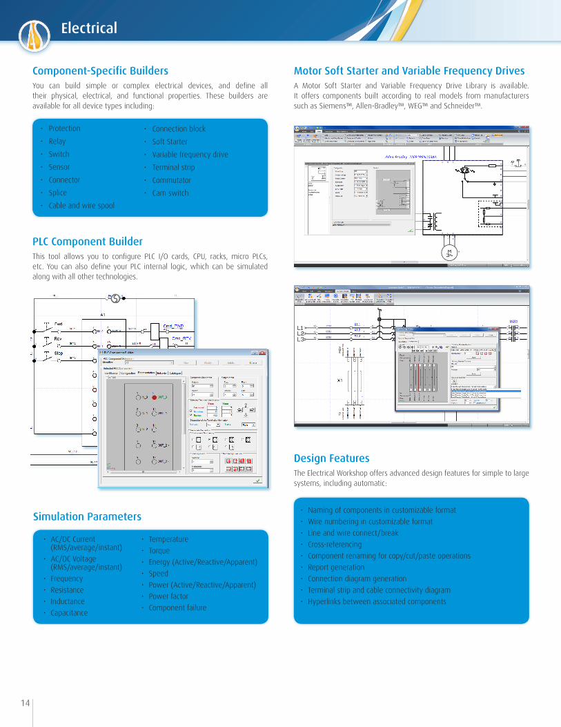
• AC/DC Current (RMS/average/instant)• AC/DC Voltage (RMS/average/instant)• Frequency• Resistance• Inductance• Capacitance
• Temperature• Torque • Energy (Active/Reactive/Apparent)• Speed• Power (Active/Reactive/Apparent)• Power factor• Component failure
Simulation Parameters
PLC Component BuilderThis tool allows you to configure PLC I/O cards, CPU, racks, micro PLCs, etc. You can also define your PLC internal logic, which can be simulated along with all other technologies.
Component-Specific BuildersYou can build simple or complex electrical devices, and define all their physical, electrical, and functional properties. These builders are available for all device types including:
Motor Soft Starter and Variable Frequency DrivesA Motor Soft Starter and Variable Frequency Drive Library is available. It offers components built according to real models from manufacturers such as Siemens™, Allen-Bradley™, WEG™ and Schneider™.
• Protection
• Relay
• Switch
• Sensor
• Connector
• Splice
• Cable and wire spool
• Connection block
• Soft Starter
• Variable frequency drive
• Terminal strip
• Commutator
• Cam switch
• Naming of components in customizable format• Wire numbering in customizable format• Line and wire connect/break• Cross-referencing• Component renaming for copy/cut/paste operations• Report generation• Connection diagram generation• Terminal strip and cable connectivity diagram• Hyperlinks between associated components
Design FeaturesThe Electrical Workshop offers advanced design features for simple to large systems, including automatic:
Electrical

15
Electrical Control SystemsThis library is useful for users who do not require the full power of the Electrical workshop. It provides the CAD functionality required to build electrical systems to control other circuits such as hydraulics or pneumatics.
IEC and JIC Symbol StandardsAll the symbols in the library comply with IEC and JIC standards. The library comes with switches, relays, solenoids, counters, push buttons, and much more.
Seamless Integration with all Other WorkshopsAll the components of the basic Electrical Control workshop interact with their matching component families in other libraries. Therefore, building complete interactive systems becomes quick and easy. Furthermore, by using the OPC module, it is possible to test a PLC program, as you can connect it to the simulated electrical system for testing purposes.
Automation Studio™ features a basic Electrical Controls Library providing quick control functions. This library complements the Pneumatic and Hydraulic workshops.
The Digital Electronics workshop comes complete with standard devices including inverters, logic gates, flip-flops, counters, shift registers, comparators, switches, LEDs, 7-bar display, decoders, multiplexers and more. Everything needed to implement basic to complex logic is available.
Digital Electronics
Electrical Controls
Flui
d Po
wer
HMI &
Con
trol
Pan
els
Elec
tric
alAu
tom
atio
nCa
talo
gues
Appl
icat
ions
Over
view

• Design of standalone power networks, power plants, and substations• Diagram representation according to your company standards • Complete electrical network simulation without disrupting current operations • Full IEC and NEMA standards support• Full range of analysis and validation tools• Realistic training environment to prepare operators to work efficiently and safely in all conditions• Switching plan testing and validation in a safe virtual environment
16
Create, visualize, document and simulate diagrams for all voltage levels in a typical one-line representation of networks for power generation, transmission and distribution.
Extensive Component Library The One-Line Electrical Library is complete. It includes components such as circuit breakers, disconnectors, power transformers, metering transformers, loads, grounds, as well as the usual automation parts (line permutators, regulators, etc.), and protection devices.
Naming RulesAutomation Studio™ offers flexible and intelligent tools in order to automatically generate identifiers for components, which simplifies the task of general design. This is achieved through the use of standards and naming rules in association with intelligent components. Components names are automatically generated by analyzing equipotentiality and connections.
One-Line Electrical Diagram

17
Detailed Switching PlansIn an electrical installation, operators are required to prepare detailed switching plans before making any configuration changes. A set of rules must be observed to ensure the safety of the installation, the network and the staff. Traditionally, operators work primarily with a paper copy of the facility’s one-line diagrams.
Automation Studio™ allows you to perfectly recreate the current facility’s one-line diagrams. To this static display, the simulation adds dynamic and colour-coded representation of equipment and lines according to their status, as well as instruments and measurements. The operator can change the state of any operable component and observe the effect on the complete installation.
The simulator calculates the continuous power flow, according to the load representation and the network’s initial state entered by the operator. The effect of each action is displayed immediately. The entire plan can be validated step by step, and different alternatives can be tested if necessary, prior to its implementation. This represents an excellent training platform for improving operator skill.
Diagnostic ToolsA rich set of Diagnostic Tools allows designers to quickly verify the quality of diagrams, from simple methods such as checking for free connectors to more sophisticated ones that confirm voltage level consistency in equipotential areas.
Procedure's example applied to the circuit below
One-Line Electrical Diagram
Flui
d Po
wer
HMI &
Con
trol
Pan
els
Elec
tric
alAu
tom
atio
nCa
talo
gues
Appl
icat
ions
Over
view

• Design automation controls faster• Easily troubleshoot simple to large projects• Indispensable to ensure system commissioning• Help in training personnel on operations and improving overall project quality
Design Automation Controls FasterSFC/GRAFCET is the method of choice to design structured automation controls. It brings a new dimension to building projects easily and efficiently. SFC/GRAFCET helps design sequences of operation quickly and validate a project prior to its implementation. It complements project documentation by helping engineers, customers, and maintenance personnel to understand equipment operations.
Trade Oriented Editor This module offers special editing functions and features especially adapted to create SFC/GRAFCET. Combined with the system design features, this provides a user-friendly and efficient environment that helps in productivity gains.
SFC/GRAFCET Code Import/Export Automation Studio™ can import SFC/GRAFCET code either in XML or in Cadepa™ software format. It also allows you to export SFC/GRAFCET into Siemens™ S7 PLC and XML format. Hence, you can import directly into the Siemens™ programming software. With the XML format, device specific compilers could create virtually any type of machine code.
18
With the SFC/GRAFCET, Automation Studio™ becomes a complete automation project specification environment. It is the tool of choice to implement SFC control structures according to the IEC 61131-3 international standard for PLC programming languages.
Sequential Function Chart/GRAFCET
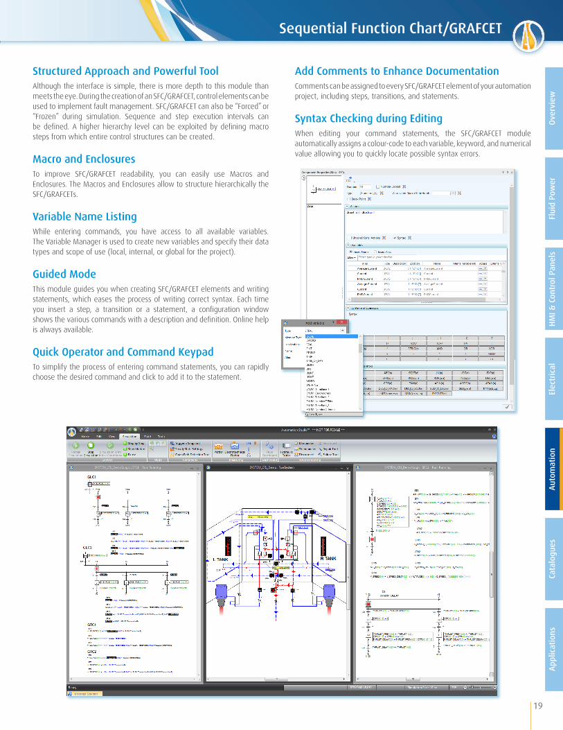
Structured Approach and Powerful ToolAlthough the interface is simple, there is more depth to this module than meets the eye. During the creation of an SFC/GRAFCET, control elements can be used to implement fault management. SFC/GRAFCET can also be “Forced” or “Frozen” during simulation. Sequence and step execution intervals can be defined. A higher hierarchy level can be exploited by defining macro steps from which entire control structures can be created.
Macro and EnclosuresTo improve SFC/GRAFCET readability, you can easily use Macros and Enclosures. The Macros and Enclosures allow to structure hierarchically the SFC/GRAFCETs.
Variable Name ListingWhile entering commands, you have access to all available variables. The Variable Manager is used to create new variables and specify their data types and scope of use (local, internal, or global for the project).
Guided ModeThis module guides you when creating SFC/GRAFCET elements and writing statements, which eases the process of writing correct syntax. Each time you insert a step, a transition or a statement, a configuration window shows the various commands with a description and definition. Online help is always available.
Quick Operator and Command KeypadTo simplify the process of entering command statements, you can rapidly choose the desired command and click to add it to the statement.
Add Comments to Enhance DocumentationComments can be assigned to every SFC/GRAFCET element of your automation project, including steps, transitions, and statements.
Syntax Checking during EditingWhen editing your command statements, the SFC/GRAFCET module automatically assigns a colour-code to each variable, keyword, and numerical value allowing you to quickly locate possible syntax errors.
19
Sequential Function Chart/GRAFCET
Flui
d Po
wer
HMI &
Con
trol
Pan
els
Elec
tric
alAu
tom
atio
nCa
talo
gues
Appl
icat
ions
Over
view
20
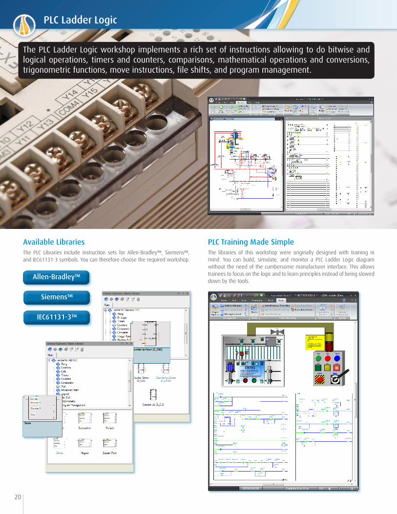
PLC Training Made SimpleThe libraries of this workshop were originally designed with training in mind. You can build, simulate, and monitor a PLC Ladder Logic diagram without the need of the cumbersome manufacturer interface. This allows trainees to focus on the logic and to learn principles instead of being slowed down by the tools.
Available LibrariesThe PLC Libraries include instruction sets for Allen-Bradley™, Siemens™, and IEC61131-3 symbols. You can therefore choose the required workshop.
Allen-Bradley™
Siemens™
IEC61131-3™
The PLC Ladder Logic workshop implements a rich set of instructions allowing to do bitwise and logical operations, timers and counters, comparisons, mathematical operations and conversions, trigonometric functions, move instructions, file shifts, and program management.
PLC Ladder Logic
21
Automation Studio™ Automation Studio™ or Other Software
OPCserver
OPCclient
Automation Studio™
Control DevicesPLC
OPCclient
OPCserver
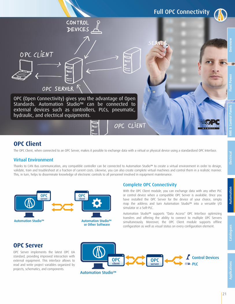
OPC ClientThe OPC Client, when connected to an OPC Server, makes it possible to exchange data with a virtual or physical device using a standardized OPC Interface.
Virtual Environment Thanks to CAN Bus communication, any compatible controller can be connected to Automation Studio™ to create a virtual environment in order to design, validate, train and troubleshoot at a fraction of current costs. Likewise, you can also create complete virtual machines and control them in a realistic manner. This, in turn, helps to disseminate knowledge of electronic controls to all personnel involved in equipment maintenance.
OPC ServerOPC Server implements the latest OPC UA standard, providing improved interaction with external equipment. This interface allows to read and write project variables organized by projects, schematics, and components.
Complete OPC ConnectivityWith the OPC Client module, you can exchange data with any other PLC or control device when a compatible OPC Server is available. Once you have installed the OPC Server for the device of your choice, simply map the address and turn Automation Studio™ into a versatile I/O simulator or a Soft-PLC.
Automation Studio™ supports "Data Access" OPC Interface optimizing transfers and offering the ability to connect to multiple OPC Servers simultaneously. Moreover, the OPC Client module supports offline configuration as well as visual status on every configuration element.
OPC (Open Connectivity) gives you the advantage of Open Standards. Automation Studio™ can be connected to external devices such as controllers, PLCs, pneumatic, hydraulic, and electrical equipments.
Full OPC Connectivity
Flui
d Po
wer
HMI &
Con
trol
Pan
els
Elec
tric
alAu
tom
atio
nCa
talo
gues
Appl
icat
ions
Over
view

22
• Trade-oriented towards fluid power and electrical technologies• Increased engineering productivity with advanced search capabilities• User friendly interface for product selection / E-Shopping• Efficient product documentation management• Facilitate data transfer between ERPs and Automation Studio™• Full import and export functions
Make your Own Catalogues and Parts DatabaseYou can create various catalogues based on raw or structured data. To import data, the Catalogue Manager supplies a structured exchange file that is compatible with SQL based databases, thus facilitating the transfer from catalogues or ERP data.
Complete Product DocumentationYou will be able to manage complete documentation related to your products including:
Import catalogues and MRP data easily into Automation Studio™, and give your employees access to product information, whenever needed during project implementation.
Flexible Web-Based ApplicationThe Catalogue Manager is integrated with Automation Studio™. It can also be deployed as a stand-alone application. This module supports:
• Product categorization• Technical data• Geographical locations, pricing and currencies• Symbols• Units (metric or imperial)• Images
• Technical specifications sheets• 3D views• Product version, revision, and validation state• External links• Commercial information• Any other related information: videos, users guide, etc.
Product Options ManagementThe Catalogue Manager offers an XML editor enabling you to produce a part number generator to select product options along with corresponding symbol and behaviour.
• Full LAN, WAN, and Web access• Multi-user environment• History of events• Security management• API and scripts functions
Powerful Search Engine In order to identify the right product faster and with improved accuracy, two search modes are available and applicable to selected catalogues:
• Structured queries using technical data and component properties;
• Full text search.
You can narrow your search by entering other criterias applicable to search results.
Catalogue Manager

• Bench tested components from renown manufacturers• Component options management• Projects created with manufacturers’ parameters• Instant access to the latest versions• Detailed product information in one common environment
23
Trade Oriented Catalogues Tailored for OEM’s, Vendors, and Systems IntegratorsThe Manufacturers’ Catalogues include components and models from major fluid power manufacturers that are pre-configured with accurate simulation parameters and ready to use.
Product Selection and ComparisonBy having access to complete product information in a single environment, comparison between various components is simplified and will speed up your decision-making.
Easy Access to Manufacturers’ Specifications and Interactive 3D ViewEach component has been carefully and rigorously bench tested within Automation Studio™ to ensure that the simulation meets a manufacturer’s typical application and performance specifications. The virtual test benches provided also help understanding the components’ behaviour and validate product selection. 3D view, product properties, technical data, images, notes, documentation, complementary accessories, etc., are available in one click.
The products categorization is based on ISO standards and NFPA recommendations. Component status is shown for each product.
On-Demand Specific ComponentsIf the available catalogues do not include the products you need, you can request for them to be added. Simply provide us with the complete part number and related manufacturers’ information and our team will include them in the development priorities.
Instant Access to the Latest Versions Your subscription gives access to the latest catalogues’ versions. Simply visit our website to download them instantly.
Sign up to the Manufacturers’ Catalogues and get unlimited access to manufacturers' preconfigured components for faster design and complete documentation.
Manufacturers’ Catalogues
Flui
d Po
wer
HMI &
Con
trol
Pan
els
Elec
tric
alAu
tom
atio
nCa
talo
gues
Appl
icat
ions
Over
view
24
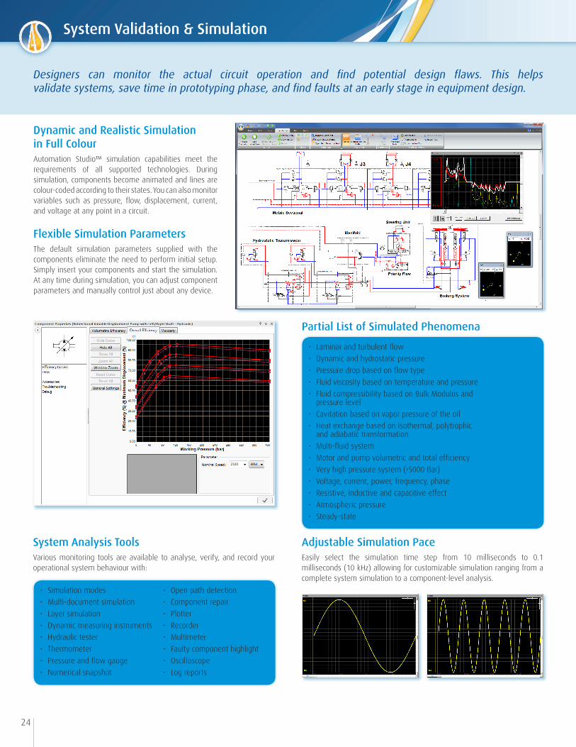
Dynamic and Realistic Simulation in Full ColourAutomation Studio™ simulation capabilities meet the requirements of all supported technologies. During simulation, components become animated and lines are colour-coded according to their states. You can also monitor variables such as pressure, flow, displacement, current, and voltage at any point in a circuit.
Flexible Simulation ParametersThe default simulation parameters supplied with the components eliminate the need to perform initial setup. Simply insert your components and start the simulation. At any time during simulation, you can adjust component parameters and manually control just about any device.
Designers can monitor the actual circuit operation and find potential design flaws. This helps validate systems, save time in prototyping phase, and find faults at an early stage in equipment design.
Partial List of Simulated Phenomena
System Analysis Tools Various monitoring tools are available to analyse, verify, and record your operational system behaviour with:
Adjustable Simulation PaceEasily select the simulation time step from 10 milliseconds to 0.1 milliseconds (10 kHz) allowing for customizable simulation ranging from a complete system simulation to a component-level analysis.
• Simulation modes• Multi-document simulation• Layer simulation• Dynamic measuring instruments• Hydraulic tester• Thermometer• Pressure and flow gauge• Numerical snapshot
• Open path detection• Component repair• Plotter• Recorder• Multimeter• Faulty component highlight• Oscilloscope• Log reports
• Laminar and turbulent flow• Dynamic and hydrostatic pressure• Pressure drop based on flow type• Fluid viscosity based on temperature and pressure• Fluid compressibility based on Bulk Modulus and pressure level• Cavitation based on vapor pressure of the oil• Heat exchange based on isothermal, polytrophic and adiabatic transformation• Multi-fluid system• Motor and pump volumetric and total efficiency• Very high pressure system (›5000 Bar)• Voltage, current, power, frequency, phase• Resistive, inductive and capacitive effect• Atmospheric pressure • Steady-state
System Validation & Simulation

• Generic training• Machine type specific training
25
Seamless Synergy from Engineering to Training with Great Cost-Savings Project documentation created by an Engineering Department can be reused by Training and Technical Publications departments, thus reducing the burden on instructors to redesign schematics and draw expensive training illustrations. Instead they can focus on concepts that need to be illustrated.
Online TrainingAutomation Studio™ is SCORM compliant and allows you to easily integrate it into your Learning Management System (LMS). You also benefit from a remote access licence connection for trainers and trainees. For example, you can prepare your courses and trainings from home or workplace.
Create Dynamic, Animated, and Flexible Training Material Automation Studio™ allows the creation of comprehensive and high-level training material. Thanks to the recording feature, you can generate countless operation sequences to illustrate equipment behaviour and help trainees quickly and easily understand machine operation and troubleshooting procedures.
Given the diversity of technical knowledge and levels of expertise, the use of a tool to visualize, monitor and accurately simulate the actual system behaviour, represents a major asset for a better understanding of its operation and troubleshooting techniques.
Training
Flui
d Po
wer
HMI &
Con
trol
Pan
els
Elec
tric
alAu
tom
atio
nCa
talo
gues
Appl
icat
ions
Over
view
26
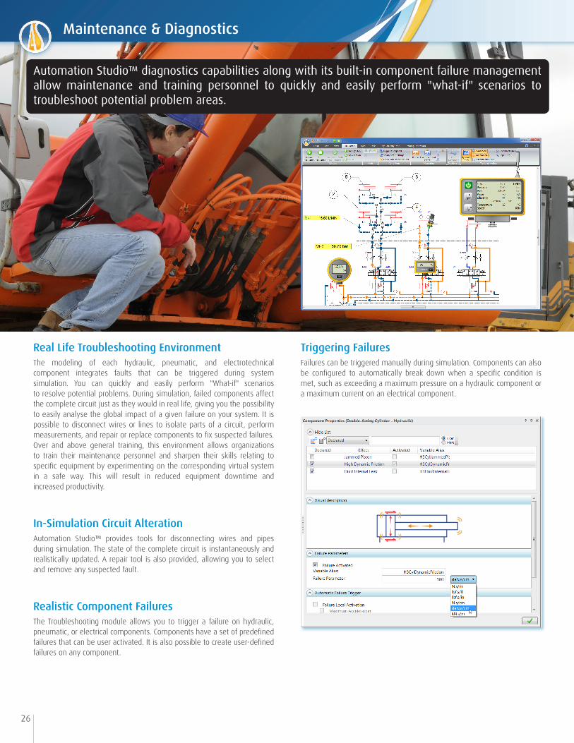
Real Life Troubleshooting EnvironmentThe modeling of each hydraulic, pneumatic, and electrotechnical component integrates faults that can be triggered during system simulation. You can quickly and easily perform "What-if" scenarios to resolve potential problems. During simulation, failed components affect the complete circuit just as they would in real life, giving you the possibility to easily analyse the global impact of a given failure on your system. It is possible to disconnect wires or lines to isolate parts of a circuit, perform measurements, and repair or replace components to fix suspected failures. Over and above general training, this environment allows organizations to train their maintenance personnel and sharpen their skills relating to specific equipment by experimenting on the corresponding virtual system in a safe way. This will result in reduced equipment downtime and increased productivity.
In-Simulation Circuit AlterationAutomation Studio™ provides tools for disconnecting wires and pipes during simulation. The state of the complete circuit is instantaneously and realistically updated. A repair tool is also provided, allowing you to select and remove any suspected fault.
Realistic Component FailuresThe Troubleshooting module allows you to trigger a failure on hydraulic, pneumatic, or electrical components. Components have a set of predefined failures that can be user activated. It is also possible to create user-defined failures on any component.
Triggering FailuresFailures can be triggered manually during simulation. Components can also be configured to automatically break down when a specific condition is met, such as exceeding a maximum pressure on a hydraulic component or a maximum current on an electrical component.
Automation Studio™ diagnostics capabilities along with its built-in component failure management allow maintenance and training personnel to quickly and easily perform "what-if" scenarios to troubleshoot potential problem areas.
Maintenance & Diagnostics
27
CAN Bus
OPC
Control Devices
CAN Bus Control
Automation Studio™
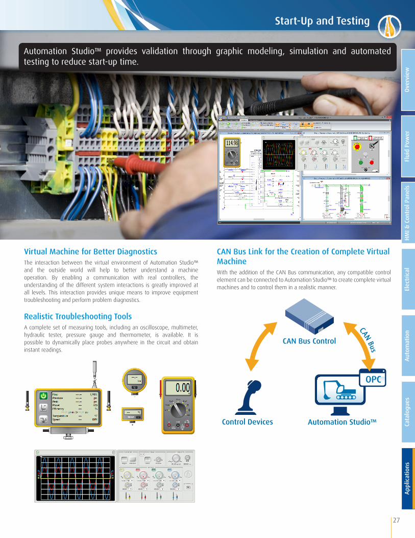
Virtual Machine for Better Diagnostics The interaction between the virtual environment of Automation Studio™ and the outside world will help to better understand a machine operation. By enabling a communication with real controllers, the understanding of the different system interactions is greatly improved at all levels. This interaction provides unique means to improve equipment troubleshooting and perform problem diagnostics.
Realistic Troubleshooting ToolsA complete set of measuring tools, including an oscilloscope, multimeter, hydraulic tester, pressure gauge and thermometer, is available. It is possible to dynamically place probes anywhere in the circuit and obtain instant readings.
CAN Bus Link for the Creation of Complete Virtual MachineWith the addition of the CAN Bus communication, any compatible control element can be connected to Automation Studio™ to create complete virtual machines and to control them in a realistic manner.
Automation Studio™ provides validation through graphic modeling, simulation and automated testing to reduce start-up time.
Start-Up and Testing
Flui
d Po
wer
HMI &
Con
trol
Pan
els
Elec
tric
alAu
tom
atio
nCa
talo
gues
Appl
icat
ions
Over
view
• Promotional/Sales documentation• Easily troubleshoot simple to large projects• Product specifications• Training material• Maintenance manuals
28
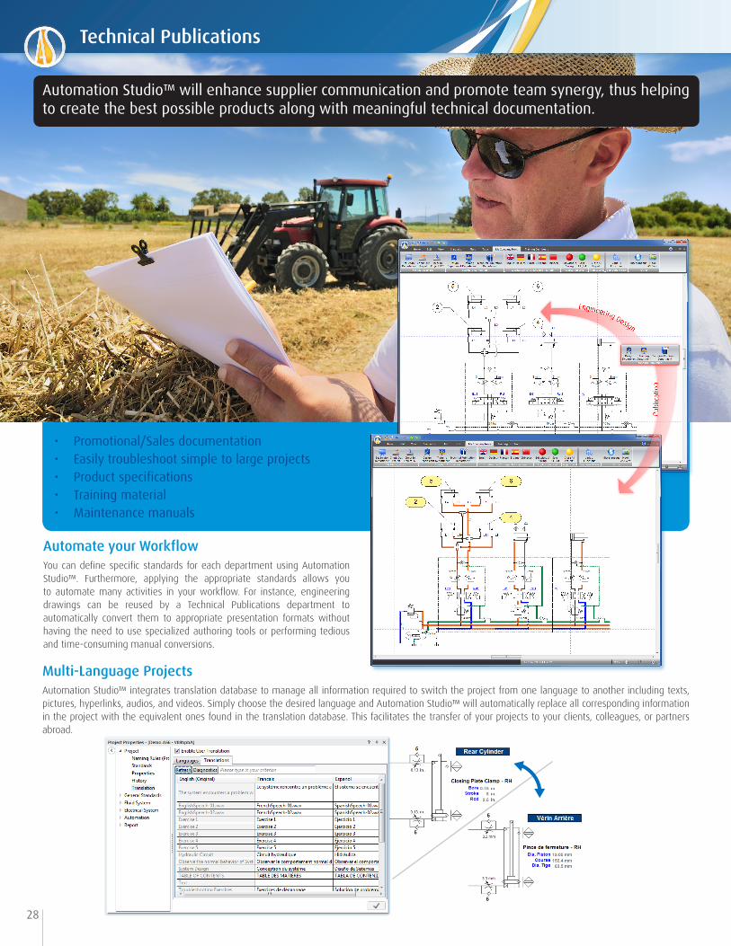
Automate your Workflow You can define specific standards for each department using Automation Studio™. Furthermore, applying the appropriate standards allows you to automate many activities in your workflow. For instance, engineering drawings can be reused by a Technical Publications department to automatically convert them to appropriate presentation formats without having the need to use specialized authoring tools or performing tedious and time-consuming manual conversions.
Multi-Language ProjectsAutomation Studio™ integrates translation database to manage all information required to switch the project from one language to another including texts, pictures, hyperlinks, audios, and videos. Simply choose the desired language and Automation Studio™ will automatically replace all corresponding information in the project with the equivalent ones found in the translation database. This facilitates the transfer of your projects to your clients, colleagues, or partners abroad.
Automation Studio™ will enhance supplier communication and promote team synergy, thus helping to create the best possible products along with meaningful technical documentation.
Technical Publications

29
Catalogue Network
Storage-Company StandardsNetwork
Storage-User Options and Preferences
Local User n
AutomationStudio™ Project Document
Document Properties
Project Properties
Standards
Thanks to its extensive automatic documentation features, Automation Studio™ will help you produce various documents easily and quickly, thus increasing your productivity and reducing data entry errors.
Manage your StandardsStandards can be defined at different hierarchical levels including: company, divisions, branches, projects, and documents. They cover every aspect of a project for both technologies and documentation including: fluid, material, hoses, lines, wires, cables, connectors, font, colour, page layout, naming rules, components, title block, component representation during editing and simulation, etc.
Automatic Report FeaturesCreating various reports is an indispensable feature for all design and sales specialists. You can quickly assign data such as part numbers, prices, descriptions, and all technical data to each component of a project in order to automatically generate bill of materials, requests for quotes, or budgetary estimates. Manufacturers’ catalogues allow you to have instant access to all specific technical data, thus avoiding the burden of gathering such informa-tion.
Export your ProjectsYou can export schematics and project data in different formats for better integration with other engineering tools or PDM systems. For instance, graphical data can be exported in various formats such as DXF, EMF, PDF, SVG, or TIFF. Moreover, to facilitate data transfer to other software, projects can be exported in XML format.
Available Reports• Bill of Materials• Purchase orders• Cross-references• Wires and cables• Terminal strips• Tags • Splices• Connectors• PLCs• Spools• Ducts• Rails• Customized reports
Configurable TooltipsDetailed information is displayed when hovering over an object on the screen, providing quick access to pertinent component properties.
Project Documentation
Flui
d Po
wer
HMI &
Con
trol
Pan
els
Elec
tric
alAu
tom
atio
nCa
talo
gues
Appl
icat
ions
Over
view
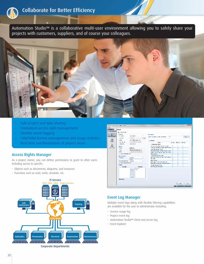
• Safe project and data sharing• Centralized access right management• Flexible event logging• LAN/WAN licence management and usage statistics• Real time synchronization of project views
Hydraulics Pneumatics Electrical Automation Maintenance
Corporate Departments
Subcontractors
LAN/WAN
(ERP, PDM, LMS)IT Service
Project Servers
Training
30
Access Rights ManagerAs a project owner, you can define permissions to grant to other users including access to specific:
• Objects such as documents, diagrams, and resources• Functions such as read, write, simulate, etc.
Event Log ManagerMultiple event logs along with flexible filtering capabilities are available for the user or administrator including:
• Licence usage log• Project event log• Automation Studio™ client and server log• Event Explorer
Automation Studio™ is a collaborative multi-user environment allowing you to safely share your projects with customers, suppliers, and of course your colleagues.
Collaborate for Better Efficiency
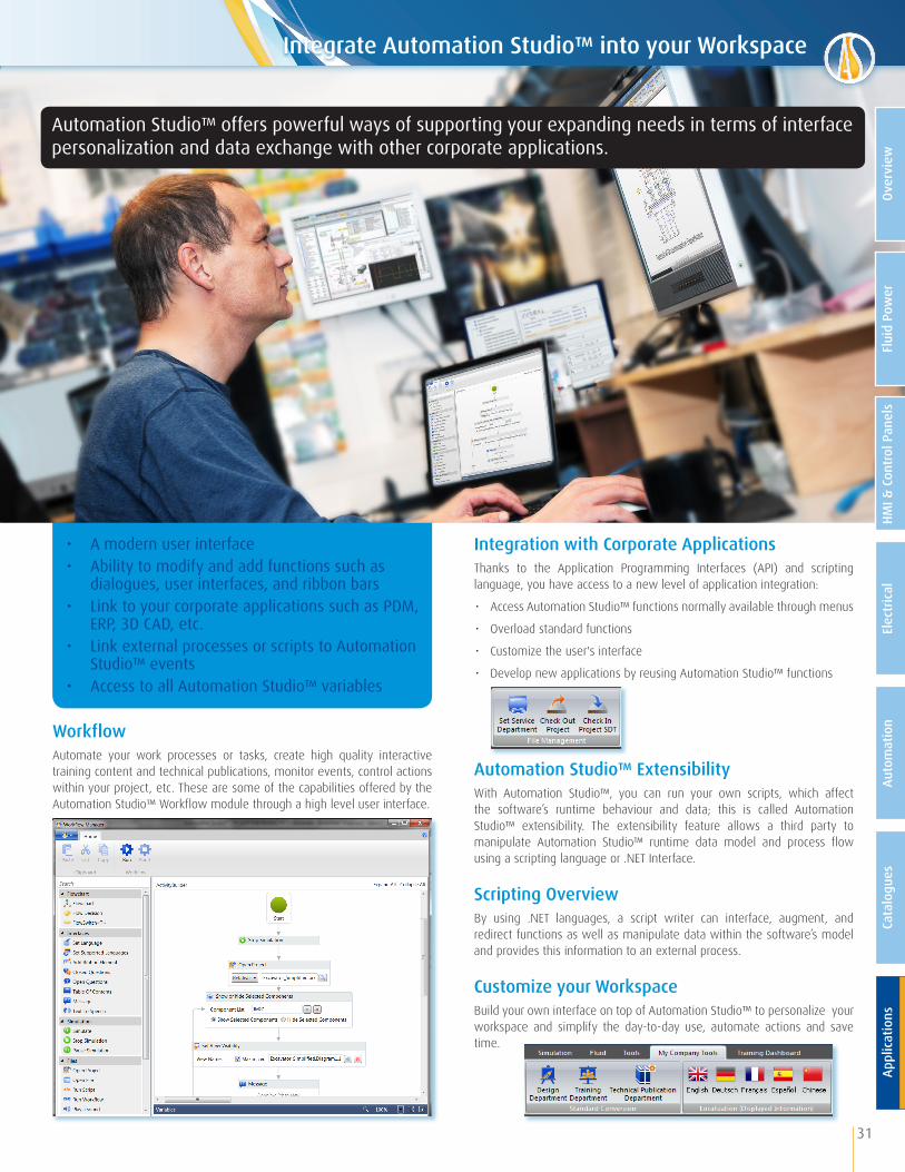
• A modern user interface• Ability to modify and add functions such as dialogues, user interfaces, and ribbon bars• Link to your corporate applications such as PDM, ERP, 3D CAD, etc.• Link external processes or scripts to Automation Studio™ events• Access to all Automation Studio™ variables
31
Integration with Corporate Applications Thanks to the Application Programming Interfaces (API) and scripting language, you have access to a new level of application integration:
∙ Access Automation Studio™ functions normally available through menus
∙ Overload standard functions
∙ Customize the user's interface
∙ Develop new applications by reusing Automation Studio™ functions
Workflow Automate your work processes or tasks, create high quality interactive training content and technical publications, monitor events, control actions within your project, etc. These are some of the capabilities offered by the Automation Studio™ Workflow module through a high level user interface.
Automation Studio™ Extensibility With Automation Studio™, you can run your own scripts, which affect the software’s runtime behaviour and data; this is called Automation Studio™ extensibility. The extensibility feature allows a third party to manipulate Automation Studio™ runtime data model and process flow using a scripting language or .NET Interface.
Scripting Overview By using .NET languages, a script writer can interface, augment, and redirect functions as well as manipulate data within the software’s model and provides this information to an external process.
Customize your WorkspaceBuild your own interface on top of Automation Studio™ to personalize your workspace and simplify the day-to-day use, automate actions and save time.
Automation Studio™ offers powerful ways of supporting your expanding needs in terms of interface personalization and data exchange with other corporate applications.
Integrate Automation Studio™ into your Workspace
Flui
d Po
wer
HMI &
Con
trol
Pan
els
Elec
tric
alAu
tom
atio
nCa
talo
gues
Appl
icat
ions
Over
view
Canada (Head Office)Famic Technologies Inc.350-9999 Cavendish Montréal, QC, H4M 2X5, Canada +1 514 748-8050+1 514 748-7169
GermanyFamic Technologies GmbHAgnes-Pockels-Bogen 180992 München, Deutschland+49 89 189 453 90+49 89 189 453 930
www.automationstudio.com | www.famictech.com
Automation Studio™ is the property of Famic Technologies Inc. All trademarks are the property of their respective owners. Printed in Canada. FT-PRE-80116
Famic Technologies focuses on customer satisfaction. We have established a strong reputation amongst Fortune 500 companies as well as small OEMs, and we make no compromises to keep it that way. We have a rich pool of specialists to put to work on your needs in order to make the implementation of your solution a success. Whether it is engineering, training, application-specific coaching, or Automation Studio™ customization, we have what it takes to support your organization.
TrainingWe provide a large array of training sessions. Call us to get more information on our seminars, webinars, on-site and off-site training packages, as well as our consulting services.
Configuration and Catalogues ImplementationBenefit from our expertise to customize your catalogues as per your needs and to integrate them into Automation Studio™.
Broad Expertise for Project SuccessOver and above software and system design, our expertise covers many fields in applied industrial engineering including mechanical, electrical, and automation engineering. No matter what your application is, our experts will be there to assist you.
Live Online DemonstrationLearn more about Automation Studio™ with a free live online demonstration with one of our specialists. Find out why the top manufacturing companies, as well as construction, mining, forestry, and agricultural OEMs, are using Automation Studio™ more and more for their applications. Contact us now to schedule your demonstration.
Annual Maintenance and Extended Support PlanSubscribe to our Annual Maintenance Program and take full advantage of the possibilities offered by Automation Studio™. This program grants you exclusive rewards such as an unlimited access to technical support, access to ALL upgrades, and the latest developments of Automation Studio™ as soon as they are available.
Software Consulting ServicesFor more than 25 years, Famic Technologies has been participating in strategic systems‘ development of our customer's operations. Our team has always delivered outstanding performance. We have implemented a rigorous development methodology, which we apply to every project. This structured approach allows all parties involved to participate during every step of the project ensuring that the solution fulfills your exact needs.
Distributed by
A Product of


![2011-05-20 Company Presentation.ppt [Kompatibilitätsmodus] Publications... · 5/20/2011 · Company Presentation Page 3 Profile Deufol is a flexible, intelligent, innovative solution](https://img.pdfslide.net/doc/110x75/601ca2293ad6f440535980a9/2011-05-20-company-kompatibilittsmodus-publications-5202011-company.jpg)