Embed Size (px)
Citation preview
AN ALTERNATIVES ANALYSIS For Improving Fish Passage Conditions at Four Road-Stream Crossings within
San Francisquito Creek Watershed, California
February 13, 2004
Prepared for:
The San Francisquito Watershed Council
Prepared by:
Michael Love, Hydrologist Michael Love & Associates
Steven Allen, P.E. Winzler & Kelly Consulting Engineers
Michael Love & AssociatesHydrologic Solutions
PO Box 4477, Arcata CA, 95518 (707) 476-8938 • [email protected]

TABLE OF CONTENTS Background ___________________________________________________________ 1
Project Objectives_______________________________________________________ 1
Scope of Work _________________________________________________________ 1
Project Activities________________________________________________________ 2
Project Cost Estimates ________________________________________________ 2 Permitting _________________________________________________________ 3
References __________________________________________________________ 4
Los Trancos Creek at Los Trancos Road ____________________________________ 5
Existing Conditions___________________________________________________ 5 Hydraulic Capacity and Overbank Flow__________________________________ 5 Fish Passage Conditions ______________________________________________ 5 Geomorphic Assessment of the Site _____________________________________ 6
Considered Alternatives _______________________________________________ 6 Full Replacement of Stream Crossing ___________________________________ 7 Install Grade Control to Stabilize Knick Point _____________________________ 7
Preferred Alternative _________________________________________________ 8 Installation of Baffles in Culvert________________________________________ 8 Roughen the Downstream Channel to Reduce Outlet Drop ___________________ 8
Preliminary Estimate of Probable Project Cost____________________________ 9
Los Trancos Creek at Fire Access Road ____________________________________ 14
Existing Conditions__________________________________________________ 14 Hydraulic Capacity and Overbank Flow_________________________________ 14 Fish Passage Conditions _____________________________________________ 14 Geomorphic Assessment of the Site ____________________________________ 15
Considered Alternatives ______________________________________________ 15 Full Replacement of Stream Crossing __________________________________ 15
Preferred Alternative ________________________________________________ 16 Installation of Bedload Retention Sills __________________________________ 16 Roughen the Downstream Channel to Reduce Outlet Drop __________________ 16
Preliminary Estimate of Probable Project Cost___________________________ 17
Bear Gulch Creek at Fox Hollow Road ____________________________________ 22
Existing Conditions__________________________________________________ 22 Hydraulic Capacity and Overbank Flow_________________________________ 22 Fish Passage Conditions _____________________________________________ 22 Geomorphic Assessment of the Site ____________________________________ 23
Considered Alternatives ______________________________________________ 23 Full Replacement of Stream Crossing __________________________________ 24 Boulder Jump-Pool Weirs____________________________________________ 25 Pool and Chute Fishway _____________________________________________ 26
Preferred Alternative ________________________________________________ 27 Constructing a Roughened Channel leading up to Culvert Outlet _____________ 27
Preliminary Estimate of Probable Project Cost___________________________ 28
McGarvey Gulch at Huddard Park Trail Crossing ___________________________ 35
Existing Conditions__________________________________________________ 35 Hydraulic Capacity and Overbank Flow_________________________________ 35 Fish Passage Conditions _____________________________________________ 36 Geomorphic Assessment of the Site ____________________________________ 36
Considered Alternatives ______________________________________________ 37 Prefabricated Bridge ________________________________________________ 37 Low-Profile Open-Bottom Arch_______________________________________ 37
Preferred Alternative ________________________________________________ 38 Stream Simulation Design using a Pipe Arch Culvert ______________________ 38
Preliminary Estimate of Probable Project Cost___________________________ 39
Appendix A Hydrologic Calculations ______________________________________ 44
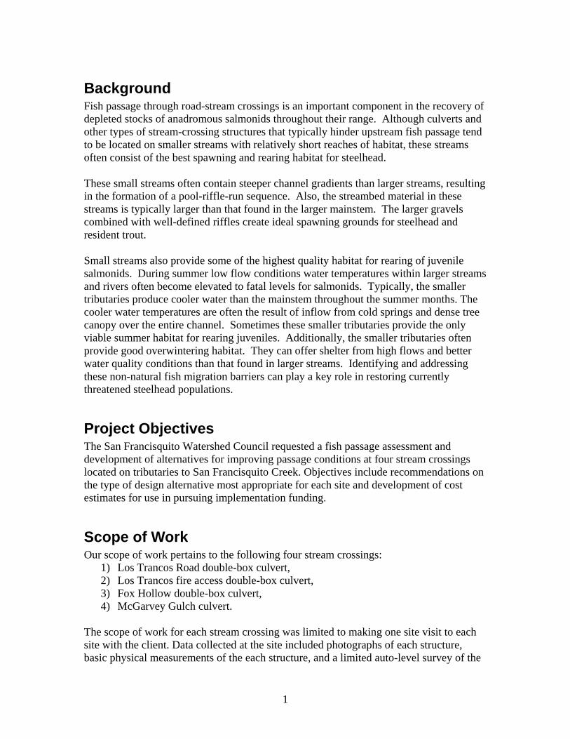
Background Fish passage through road-stream crossings is an important component in the recovery of depleted stocks of anadromous salmonids throughout their range. Although culverts and other types of stream-crossing structures that typically hinder upstream fish passage tend to be located on smaller streams with relatively short reaches of habitat, these streams often consist of the best spawning and rearing habitat for steelhead. These small streams often contain steeper channel gradients than larger streams, resulting in the formation of a pool-riffle-run sequence. Also, the streambed material in these streams is typically larger than that found in the larger mainstem. The larger gravels combined with well-defined riffles create ideal spawning grounds for steelhead and resident trout. Small streams also provide some of the highest quality habitat for rearing of juvenile salmonids. During summer low flow conditions water temperatures within larger streams and rivers often become elevated to fatal levels for salmonids. Typically, the smaller tributaries produce cooler water than the mainstem throughout the summer months. The cooler water temperatures are often the result of inflow from cold springs and dense tree canopy over the entire channel. Sometimes these smaller tributaries provide the only viable summer habitat for rearing juveniles. Additionally, the smaller tributaries often provide good overwintering habitat. They can offer shelter from high flows and better water quality conditions than that found in larger streams. Identifying and addressing these non-natural fish migration barriers can play a key role in restoring currently threatened steelhead populations.
Project Objectives The San Francisquito Watershed Council requested a fish passage assessment and development of alternatives for improving passage conditions at four stream crossings located on tributaries to San Francisquito Creek. Objectives include recommendations on the type of design alternative most appropriate for each site and development of cost estimates for use in pursuing implementation funding.
Scope of Work Our scope of work pertains to the following four stream crossings:
1) Los Trancos Road double-box culvert, 2) Los Trancos fire access double-box culvert, 3) Fox Hollow double-box culvert, 4) McGarvey Gulch culvert.
The scope of work for each stream crossing was limited to making one site visit to each site with the client. Data collected at the site included photographs of each structure, basic physical measurements of the each structure, and a limited auto-level survey of the
1
channel thalweg through each structure. The scope included preparing a brief alternative analysis for each crossing that was to include the full replacement and a modification of the existing structure. The report will give preliminary recommendations to which alternative appears best suited for each site. For each recommended alternative, the scope included estimates of probable engineering design and construction costs.
Project Activities Michael Love from Michael Love & Associates and Steve Allen P.E. from Winzler & Kelly, accompanied by Matt Stoecker with the San Francisquito Watershed Council Steelhead Task Force, visited each of the four stream crossing sites on November 18-19, 2003. At each site a limited auto-level survey was conducted to determine relative elevations of the culvert inverts and stream channel, and the channel shape and type. Visual observations were made in regard to the apparent geomorphic stability of the channel near each crossing. Various alternatives for improving fish passage conditions were discussed while on-site. Following the site visits, peak design flows and fish passage design flows were calculated for each stream crossing (Appendix A). Peak design flows were estimated using three different methods: regional regression equations, the rational method, and local stream flow records. Fish passage flows were estimated using criteria given in the NOAA Fisheries (2001) and CDFG (2003) fish passage guidelines. Fish passage conditions were assessed for juvenile salmonids and adult rainbow and steelhead trout at fish passage flows. Culvert hydraulic conditions (water depths, velocities, and outlet drops) were determined using the FishXing 2.2 software package and then compared to fish passage criteria given in the NOAA Fisheries (2001) and CDFG (2003) fish passage guidelines. Understanding the existing hydraulic conditions fish encounter at each crossing was used to help develop feasible alternatives. For each crossing, several possible fish passage improvement alternatives were identified. Each alternative’s abilities to satisfy fish passage requirements and site constraints were considered. A preferred alternative was selected based on consideration of potential project impacts and benefits, construction access limitations, and relative project costs. A preliminary estimate of probable cost was then developed for each identified preferred alternative.
Project Cost Estimates For each preferred alternative, estimates of probable costs were developed for engineering survey and design, permitting, and construction. These preliminary estimates are intended to help convey the potential costs of each preferred alternative and to aid in obtaining project funding. We did not include any costs for the Council to obtain and administer funds. Estimating costs at this early stage can vary significantly from the actual final project. Actual costs can vary due to such things as unknown site conditions, public and design review comments, regulatory actions, and contractor experience and required construction oversight. These basic changes can affect the required effort for
2
design, the actual final design, and contractor bids which in turn affect the final cost of the completed project. To account for these uncertainties, we have provided a range of costs to help convey the likely range that could be expected. The lower range may be optimistic but realized if the permitting process is straightforward and multiple projects are worked on simultaneously, allowing some economy of scale. The upper range is meant to reflect costs that could be realized if complicating factors arise, such as those described above. The upper range does not reflect a worst-case scenario, but rather a realistic upper range based on our experience with similar restoration and barrier removal projects. The preferred alternatives for the two Los Trancos Creek crossings are relatively small projects involving installation of baffles in the culvert and placing a small amount of large rock into the downstream channel. However, it is important to realize that the permitting process associated with these proposed projects remain similar to that required for much larger fish passage projects. Additionally, designing a baffle system to ensure it has little to no impact on the hydraulic capacity of the culvert requires a relatively high level of analysis. Consequently, the cost associated with design and preparation of permit applications for small projects are often disproportional to the overall cost of constructing the project when compared to budgets from larger fish passage improvement projects.
Permitting Anticipated environmental documents and permits required to implement these proposed projects include:
1. Compliance with the California Environmental Quality Act (CEQA),
2. California Department of Fish and Game Streambed Alteration Agreement (CDFG 1600), and
3. US Army Corps of Engineers Regional General Permit 1 for Fish Passage/Sediment Reduction Projects at Water Crossings (USACOE RGP 1), which includes Water Quality Certification.
Our estimates include the completion of applications and filing fees associated with the CDFG 1600 and ACOE RGP1 permits. CEQA compliance was assumed covered by the project lead agency and therefore not included in our estimates. Based on previous experience, CDFG will likely handle the CEQA process in-house if the CDFG grants program funds the projects and the San Francisquito Watershed Council acts as project proponent and grantee. Otherwise, the budgets should be adjusted to account for additional expenses associated with complying with CEQA. Permitting requirements are continually changing. For instance, CDFG may soon have a programmatic agreement with ACOE in place, which could negate the requirement for a separate RGP permit.
3
However, it is likely that the same basic information and similar permitting effort will be required. Other permits and approvals that may need to be obtained but were not included in our estimates could include:
1. US Fish and Wildlife Service requirements concerning projects occurring in designated critical habitat for threatened species. CDFG records show occurrences of California tiger salamander, western pond turtle, caper-fruited tropidocarpum, robust monardella, Franciscan onion, and western leatherwood near the four project sites. The critical habitat for red-legged frogs is being revised but surveys may still be required.
2. County or city encroachment permits.
3. County or city grading permits typically associated with projects involving moving more than 50 cubic yards of fill.
4. Fire Marshal review and approval.
5. Addendums to existing Flood Insurance Studies (FIS) for crossings that are located in Federal Emergency Management Agency (FEMA) designated 100-year flood plains. It is not known which crossings, if any, this may apply to.
References WDFW, 2003. Design of road culverts for fish passage. 110 pages.
http://wdfw.wa.gov/hab/engineer/habeng.htm#upstrm CDFG, 2003. Part IX: Fish passage evaluation at stream crossings. California Salmonid Stream Habitat Restoration Manual, Vol. II, Calif. Dept. of Fish & Game. February, 2003.
NOAA Fisheries. 2001. Guidelines for salmonid passage at stream crossings. Southwest Region. Revised May 16, 2000. 10 pages.
4
Los Trancos Creek at Los Trancos Road
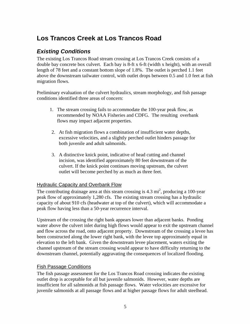
Existing Conditions The existing Los Trancos Road stream crossing at Los Trancos Creek consists of a double bay concrete box culvert. Each bay is 8-ft x 6-ft (width x height), with an overall length of 78 feet and a constant bottom slope of 1.8%. The outlet is perched 1.1 feet above the downstream tailwater control, with outlet drops between 0.5 and 1.0 feet at fish migration flows. Preliminary evaluation of the culvert hydraulics, stream morphology, and fish passage conditions identified three areas of concern:
1. The stream crossing fails to accommodate the 100-year peak flow, as recommended by NOAA Fisheries and CDFG. The resulting overbank flows may impact adjacent properties.
2. At fish migration flows a combination of insufficient water depths, excessive velocities, and a slightly perched outlet hinders passage for both juvenile and adult salmonids.
3. A distinctive knick point, indicative of head cutting and channel incision, was identified approximately 80 feet downstream of the culvert. If the knick point continues moving upstream, the culvert outlet will become perched by as much as three feet.
Hydraulic Capacity and Overbank Flow The contributing drainage area at this steam crossing is 4.3 mi2, producing a 100-year peak flow of approximately 1,280 cfs. The existing stream crossing has a hydraulic capacity of about 910 cfs (headwater at top of the culvert), which will accommodate a peak flow having less than a 50-year recurrence interval. Upstream of the crossing the right bank appears lower than adjacent banks. Ponding water above the culvert inlet during high flows would appear to exit the upstream channel and flow across the road, onto adjacent property. Downstream of the crossing a levee has been constructed along the lower right bank, with the levee top approximately equal in elevation to the left bank. Given the downstream levee placement, waters exiting the channel upstream of the stream crossing would appear to have difficulty returning to the downstream channel, potentially aggravating the consequences of localized flooding.
Fish Passage Conditions The fish passage assessment for the Los Trancos Road crossing indicates the existing outlet drop is acceptable for all but juvenile salmonids. However, water depths are insufficient for all salmonids at fish passage flows. Water velocities are excessive for juvenile salmonids at all passage flows and at higher passage flows for adult steelhead.
5
Although the crossing fails to meet current fish passage design criteria at all flows, upstream migrating adult steelhead and rainbow trout are likely able to negotiate the culvert at moderate flows when velocities are within an acceptable range but water depths remain shallow. However, these conditions are far from ideal, creating temporary low and high flow barriers to spawning steelhead, and could occasionally force them to spawn downstream of the crossing. The culvert also prevents juvenile steelhead from migrating upstream in search of potentially less crowded overwintering habitat.
Geomorphic Assessment of the Site A distinctive knick point (interruption in a stream’s longitudinal profile), indicative of head cutting and channel incision, was identified approximately 80 feet downstream of the culvert. The knick point, which can be identified in the surveyed channel profile, consisted of a short oversteepened section of channel with matching channel slopes immediately upstream and downstream of the knick point. This is a common indicator that the channel bed downstream of the knick point has recently lowered, or incised. Large scale channel incision can have numerous causes, including removal of large wood from streams, increases in peak flows due to urbanization or recent fires, or constriction of the historic channel through armoring of channel bed and banks. If left to its own accord, a knick point tends to move upstream resulting in head cutting. If the knick point in Los Trancos Creek continues moving upstream, the culvert outlet will become perched by as much as three feet, making it a severe barrier to upstream migrating steelhead. The rate at which a knick point will move upstream is largely dependent on its composition and the extent to which it resists erosion. The knick point identified in Los Trancos Creek consists of moderately resistant materials, including numerous large scoured roots and large cobbles. Matt Stoecker with the San Francisquito Watershed Council Steelhead Task Force noted that he has observed very little change in the knick point over the last several years. It would be advisable to monitor the location of the knick point by taking measurements from the culvert outlet to the knick point at regular intervals (at least annually). This information would be helpful to estimate how soon the knick point could reach the culvert and help determine if action should be taken to slow or halt the knick point from migrating upstream before it reaches the culvert.
Considered Alternatives Several alternatives aimed at improving fish passage conditions were considered before a preferred alternative was selected. They included:
• Full replacement of the stream crossing structure with a crossing that maintains a natural streambed and banks and passes the 100-year peak flow.
• Install grade control structures to prevent further headward movement of the knick point and eliminate the risk of a large perch forming at the culvert outlet.
6
• Installing baffles within the crossing to reduce water velocities and increase water depths.
• Install large rock in channel immediately below outlet to increase channel roughness and reduce or eliminate the drop at the culvert outlet.
Full Replacement of Stream Crossing Given the physical characteristics at the stream crossing location, it would be difficult to install a new crossing that could accommodate the 100-year peak flow without overtopping the road. Installing a new bottomless crossing would require addressing the potential of headcutting and channel incision. If left unchecked, the knick point would likely move upstream, destabilizing the channel, degrading the habitat, and causing the next upstream culvert to become perched. The existing crossing appears to be in reasonably good condition and adequately sized relative to the upstream and downstream channel widths. Exit velocities appear to be similar to those occurring in the natural channel, as evident by the lack of a large scour pool at the culvert outlet. Additionally, the culvert slope is relatively mild, making it suitable for retrofitting with baffles. Full replacement of the existing stream crossing would be extremely costly and have limited benefit on fish passage and aquatic habitat. Given that retrofitting the crossing could substantially improve passage for a much lower cost, full replacement was not considered the preferred alternative. However, these other alternatives should be considered as an interim measure. If significant road modifications such as road widening are planned in the future, full replacement should be considered.
Install Grade Control to Stabilize Knick Point Installing a set of grade control structures downstream of the stream crossing could be used to help stabilize the existing knick point and prevent it from moving upstream towards the culvert outlet. Conditions observed during our site visit indicated approximately a 2-foot vertical difference between the channel bed above and below the knick point, which would require excavating down into the channel bed at least three to four feet to install boulder grade control structures. This process would disturb the channel bed and banks and destroy the existing root structure that currently provides stability to this portion of the channel. Providing construction equipment access needed to preform the work would be disruptive to the streambank at the access point and require the cooperation of adjacent downstream landowners. The only observed suitable access point appears to be from the left bank next to the culvert outlet. The option of installing grade control was considered unnecessary at this time. The knick point appears relatively stable, being primarily held in place by the existing root structure, and was verbally described as being stable near this location for some time. In its current state it is not a barrier to adult fish. However, regular longitudinal surveys and
7
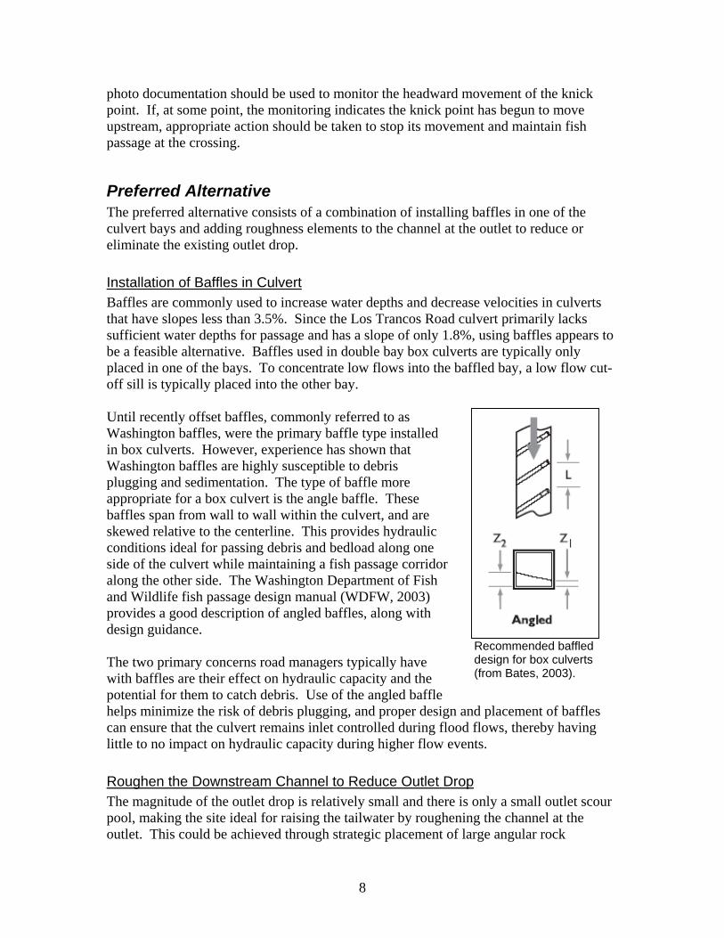
photo documentation should be used to monitor the headward movement of the knick point. If, at some point, the monitoring indicates the knick point has begun to move upstream, appropriate action should be taken to stop its movement and maintain fish passage at the crossing.
Preferred Alternative The preferred alternative consists of a combination of installing baffles in one of the culvert bays and adding roughness elements to the channel at the outlet to reduce or eliminate the existing outlet drop.
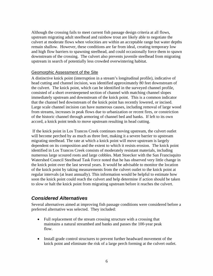
Installation of Baffles in Culvert Baffles are commonly used to increase water depths and decrease velocities in culverts that have slopes less than 3.5%. Since the Los Trancos Road culvert primarily lacks sufficient water depths for passage and has a slope of only 1.8%, using baffles appears to be a feasible alternative. Baffles used in double bay box culverts are typically only placed in one of the bays. To concentrate low flows into the baffled bay, a low flow cut-off sill is typically placed into the other bay. Until recently offset baffles, commonly referred to as Washington baffles, were the primary baffle type installed in box culverts. However, experience has shown that Washington baffles are highly susceptible to debris plugging and sedimentation. The type of baffle more appropriate for a box culvert is the angle baffle. These baffles span from wall to wall within the culvert, and are skewed relative to the centerline. This provides hydraulic conditions ideal for passing debris and bedload along one side of the culvert while maintaining a fish passage corridor along the other side. The Washington Department of Fish and Wildlife fish passage design manual (WDFW, 2003) provides a good description of angled baffles, along with design guidance.
The two primary concerns road managers typically have with baffles are their effect on hydraulic capacity and the potential for them to catch debris. Use of the angled baffle helps minimize the risk of debris plugging, and proper design and placement of baffles can ensure that the culvert remains inlet controlled during flood flows, thereby having little to no impact on hydraulic capacity during higher flow events.
Recommended baffled design for box culverts (from Bates, 2003).
Roughen the Downstream Channel to Reduce Outlet Drop The magnitude of the outlet drop is relatively small and there is only a small outlet scour pool, making the site ideal for raising the tailwater by roughening the channel at the outlet. This could be achieved through strategic placement of large angular rock
8
immediately below the outlet, likely being within the existing right-of-way of the road crossing and therefore not requiring adjacent landowner agreements. The extra roughness created by the placement of large rock below the outlet would slow water velocities, dissipate energy, and result in raising the tailwater. Although determining the extent to which it will raise the tailwater and reduce the outlet drop cannot be determined until the design phase, it is anticipated to nearly eliminate the existing drop at the culvert outlet. The rock could be placed into the channel using an excavator working from the road above the outlet. Once in the channel, experienced hand crews could move the rock into the appropriate arrangement. This avoids having heavy equipment disturb the channel banks and riparian vegetation and would likely keep the project area within the existing right-of –way of the crossing
Preliminary Estimate of Probable Project Cost Below is our estimate of probable costs for engineering design, permitting, and construction efforts to complete the preferred alternative at this site. These preliminary estimates are intended to help convey the potential costs of each preferred alternative and to aid in obtaining project funding. We did not include any costs for the Council to obtain and administer funds. Estimating costs at this early stage can vary significantly from the actual final project. Actual costs can vary due to such things as unknown site conditions, public and design review comments, regulatory actions, and contractor experience and required construction oversight. These basic changes can affect the required effort for design, the actual final design, and contractor bids which in turn affect the final cost of the completed project. To account for these uncertainties, we have provided a range of costs to help convey the likely range that could be expected. The lower range may be optimistic but realized if the permitting process is straightforward and multiple projects are worked on simultaneously, allowing some economy of scale. The upper range is meant to reflect costs that could be realized if complicating factors arise, such as those described above. The upper range does not reflect a worst-case scenario, but rather a realistic upper range based on our experience with similar restoration and barrier removal projects. Our estimate below assumes the following:
1) No additional survey required for design or hydraulic modeling of weirs,
2) One site visit included under Engineering effort to discuss proposed design with Council, public works, neighbors, or other individuals,
3) One site visit included under permitting effort to discuss proposed design and construction related issues with permitting agency personnel,
4) Estimate for permitting effort includes the anticipated $154 DFG 1600 filing fee,
9

5) Estimate for construction effort includes three days by engineer on site, likely the first three days of construction,
6) Water diversion will be necessary,
7) Traffic control will be required by contractor for rock delivery and placement.
Preliminary Estimate of Probable Project Costs For the Lower Los Trancos Double Box Culvert Weir Retrofit Alternative
Estimate Item: Item Estimate: Engineering Effort: this item includes hydrologic and hydraulic calculations and modeling, engineering design and drafting, cost estimates, one site visit to review the design with Council, property owners and/or agency personnel.
$9,000 - $11,000
Permitting Effort: this item includes time to research and complete DFG 1600 and ACOE RGP permit applications, DFG permit filing fee, and a site visit to meet with regulatory personnel to explain the project design and anticipated construction methodology. This estimate does not include special surveys, special studies, CEQA, or other potential studies or permits that may arise.
$4,000 - $5,000
Construction Effort: this item includes limited construction inspection by the engineers, and contractor costs including materials and labor to construct the preferred alternative.
$10,500 - $13,500
Total Estimate of Probable Costs for Project $23,500 - $29,500
10
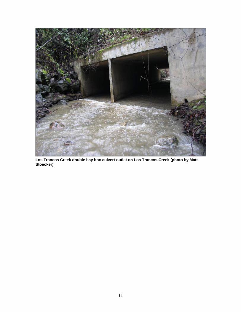
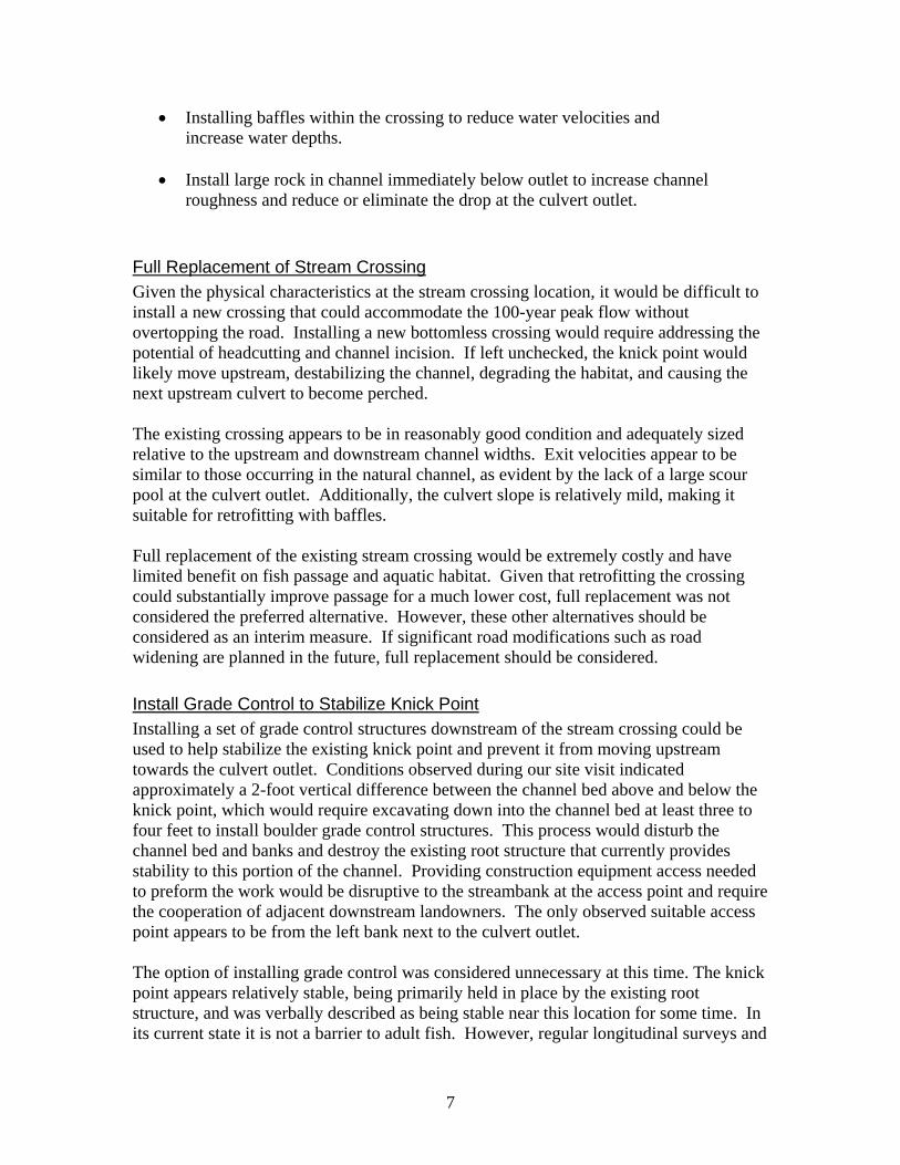
Los Trancos Creek double bay box culvert outlet on Los Trancos Creek (photo by Matt Stoecker)
11

Site: LT6 - Los Trancos CreekRoad: Lost Trancos Road
Culvert Dimensions HydrologyEnd-Section Type: Double Bay Box Drainage Area: 4.32 mi2
Material: Concrete Estimated 100-yr Flow: 1,283 cfs (from USGS Regression Eqn.)Roughness (n): 0.018Inlet Type: 45o Skewed Headwall Culvert Capacity Calculation based on FHWA Chart 12 for Skewed InletOutlet Type: 45o Skewed Headwall ENTRANCE TYPE: 45o Skewed HeadwallHeight: 6 ft Capacity (HW/D = 1.0): 672 cfsWidth: 8 ft Capacity (HW/D = 1.25): 912 cfs (top of inlet headwall)Length: 78 ftConstant Slope: 1.82%
Fish Passage Design Flows Existing Conditions at Fish Passage Design Flows
Adult SteelheadFish Speciesand Age Class
Qlp(cfs)
Water Depth(ft)
Velocity(ft/s)
Drop(ft)
Lower Passage Flow (Qlp): 3 cfs Adult Steelhead 3.0 0.04 1.40 1.00Upper Passage Flow (Qhp): 43 cfs Adult Rainbow Trout 2.0 0.07 1.85 0.96
Juvenile Salmonids 1.0 0.09 2.17 0.93Adult Rainbow Trout
Lower Passage Flow (Qlp): 2 cfsFish Speciesand Age Class
Qhp(cfs)
Water Depth(ft)
Velocity(ft/s)
Drop(ft)
Upper Passage Flow (Qhp): 13 cfs Adult Steelhead 43.3 0.43 6.19 0.53Adult Rainbow Trout 12.5 0.21 3.87 0.74
Juvenile Salmonids Juvenile Salmonids 5.4 0.12 2.66 0.87Lower Passage Flow (Qlp): 1 cfs
Upper Passage Flow (Qhp): 5 cfs
Fish Passage Criteria Flows Meet Fish Passage CriteriaAdult Steelhead Adult Steelhead
Minimum Water Depth = 1.0 ft Insufficient Depth below: 165.0 cfsMaximum Water Velocity = 5.0 ft/s Excessive Velocity above: 25.0 cfs
Maximum Outlet Drop = 1.0 ft Excessive Outlet Drop below: NONEFlows Meeting All Passage Criteria: NONE
Adult Rainbow Trout Adult Rainbow TroutMinimum Water Depth = 0.67 ft Insufficient Depth below: 82.0 cfs
Maximum Water Velocity = 4.0 ft/s Excessive Velocity above: 14.0 cfsMaximum Outlet Drop = 1.0 ft Excessive Outlet Drop below: NONE
Flows Meeting All Passage Criteria: NONE
Juvenile Salmonids Juvenile SalmonidsMinimum Water Depth = 0.5 ft Insufficient Depth below: 54.1 cfs
Maximum Water Velocity = 1.0 ft/s Excessive Velocity above: 0.5 cfsMaximum Outlet Drop = 0.5 ft Excessive Outlet Drop below: All Flows
Flows Meeting All Passage Criteria: NONE
STREAM CROSSING SUMMARY SHEET
Fish Passage Conditions
Note: Outlet Drop is the difference between the water surface elevation at the culvert outlet and the elevation of the tailwater.
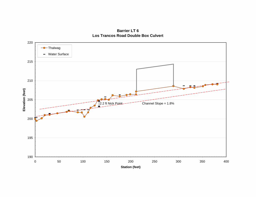
Barrier LT 6Los Trancos Road Double Box Culvert
190
195
200
205
210
215
220
0 50 100 150 200 250 300 350 400
Station (feet)
Elev
atio
n (fe
et)
Thalwag
Water Surface
2.2 ft Nick Point Channel Slope = 1.8%
Los Trancos Creek at Fire Access Road
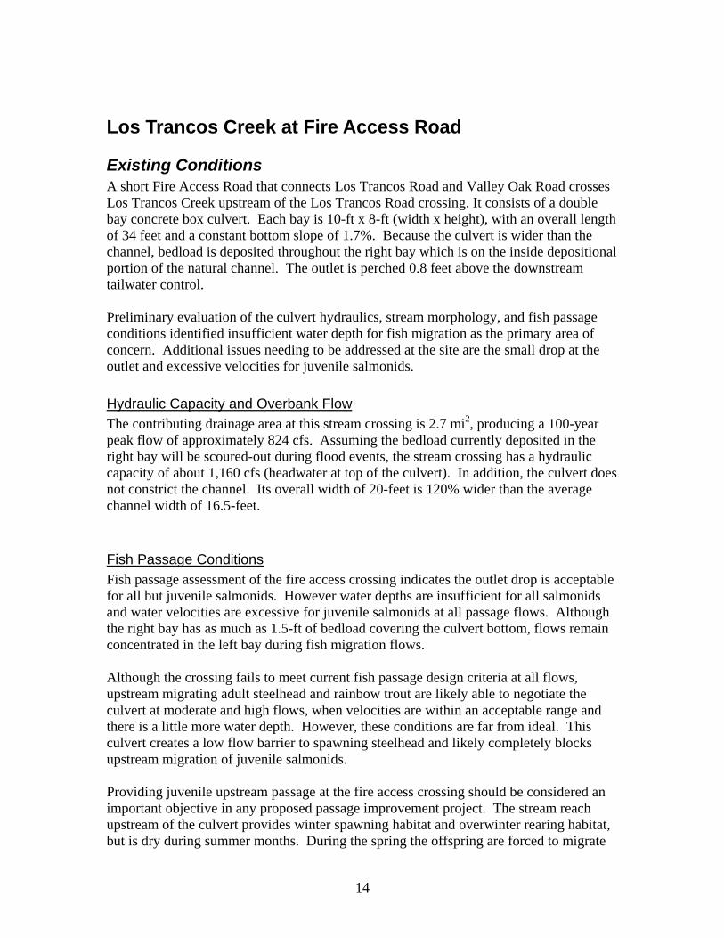
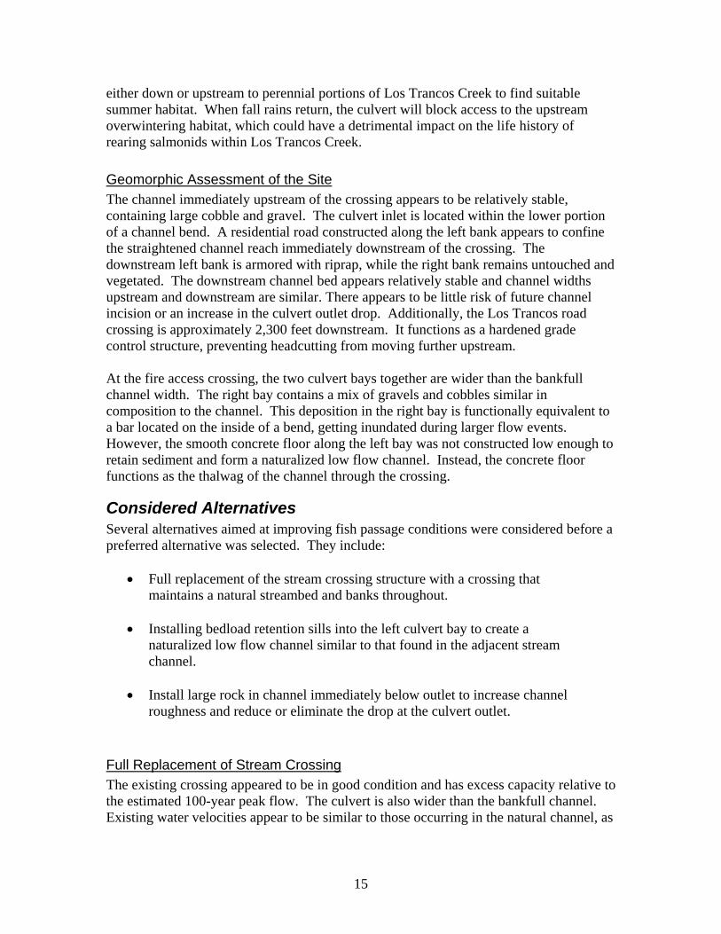
Existing Conditions A short Fire Access Road that connects Los Trancos Road and Valley Oak Road crosses Los Trancos Creek upstream of the Los Trancos Road crossing. It consists of a double bay concrete box culvert. Each bay is 10-ft x 8-ft (width x height), with an overall length of 34 feet and a constant bottom slope of 1.7%. Because the culvert is wider than the channel, bedload is deposited throughout the right bay which is on the inside depositional portion of the natural channel. The outlet is perched 0.8 feet above the downstream tailwater control. Preliminary evaluation of the culvert hydraulics, stream morphology, and fish passage conditions identified insufficient water depth for fish migration as the primary area of concern. Additional issues needing to be addressed at the site are the small drop at the outlet and excessive velocities for juvenile salmonids.
Hydraulic Capacity and Overbank Flow The contributing drainage area at this stream crossing is 2.7 mi2, producing a 100-year peak flow of approximately 824 cfs. Assuming the bedload currently deposited in the right bay will be scoured-out during flood events, the stream crossing has a hydraulic capacity of about 1,160 cfs (headwater at top of the culvert). In addition, the culvert does not constrict the channel. Its overall width of 20-feet is 120% wider than the average channel width of 16.5-feet.
Fish Passage Conditions Fish passage assessment of the fire access crossing indicates the outlet drop is acceptable for all but juvenile salmonids. However water depths are insufficient for all salmonids and water velocities are excessive for juvenile salmonids at all passage flows. Although the right bay has as much as 1.5-ft of bedload covering the culvert bottom, flows remain concentrated in the left bay during fish migration flows. Although the crossing fails to meet current fish passage design criteria at all flows, upstream migrating adult steelhead and rainbow trout are likely able to negotiate the culvert at moderate and high flows, when velocities are within an acceptable range and there is a little more water depth. However, these conditions are far from ideal. This culvert creates a low flow barrier to spawning steelhead and likely completely blocks upstream migration of juvenile salmonids. Providing juvenile upstream passage at the fire access crossing should be considered an important objective in any proposed passage improvement project. The stream reach upstream of the culvert provides winter spawning habitat and overwinter rearing habitat, but is dry during summer months. During the spring the offspring are forced to migrate
14
either down or upstream to perennial portions of Los Trancos Creek to find suitable summer habitat. When fall rains return, the culvert will block access to the upstream overwintering habitat, which could have a detrimental impact on the life history of rearing salmonids within Los Trancos Creek.
Geomorphic Assessment of the Site The channel immediately upstream of the crossing appears to be relatively stable, containing large cobble and gravel. The culvert inlet is located within the lower portion of a channel bend. A residential road constructed along the left bank appears to confine the straightened channel reach immediately downstream of the crossing. The downstream left bank is armored with riprap, while the right bank remains untouched and vegetated. The downstream channel bed appears relatively stable and channel widths upstream and downstream are similar. There appears to be little risk of future channel incision or an increase in the culvert outlet drop. Additionally, the Los Trancos road crossing is approximately 2,300 feet downstream. It functions as a hardened grade control structure, preventing headcutting from moving further upstream. At the fire access crossing, the two culvert bays together are wider than the bankfull channel width. The right bay contains a mix of gravels and cobbles similar in composition to the channel. This deposition in the right bay is functionally equivalent to a bar located on the inside of a bend, getting inundated during larger flow events. However, the smooth concrete floor along the left bay was not constructed low enough to retain sediment and form a naturalized low flow channel. Instead, the concrete floor functions as the thalwag of the channel through the crossing.
Considered Alternatives Several alternatives aimed at improving fish passage conditions were considered before a preferred alternative was selected. They include:
• Full replacement of the stream crossing structure with a crossing that maintains a natural streambed and banks throughout.
• Installing bedload retention sills into the left culvert bay to create a naturalized low flow channel similar to that found in the adjacent stream channel.
• Install large rock in channel immediately below outlet to increase channel roughness and reduce or eliminate the drop at the culvert outlet.
Full Replacement of Stream Crossing The existing crossing appeared to be in good condition and has excess capacity relative to the estimated 100-year peak flow. The culvert is also wider than the bankfull channel. Existing water velocities appear to be similar to those occurring in the natural channel, as
15

evident by the lack of a large scour pool at the culvert outlet. The culvert’s overall impact on the adjacent channels form, function, and aquatic habitat appears negligible. Full replacement of the existing stream crossing would be extremely costly and have limited benefit on fish passage and aquatic habitat. Since the existing crossing is sized well for the channel and fish passage conditions can be greatly improved using means other than full replacement, this option was not chosen as the preferred alternative.
Preferred Alternative The preferred alternative is a combination of installing bedload retention sills in the left culvert bay and to reduce or eliminate the existing outlet drop by adding roughness elements to the downstream channel.
Installation of Bedload Retention Sills The technique of creating a natural channel bed throughout the culvert is referred to as a stream simulation design. One means of maintaining a channel bed within a culvert is to use bedload retention sills. Placed along the floor of the culvert, they are intended to trap and maintain streambed substrate. They work best on crossings that do not constrict the upstream channel, such as the fire access road crossing. If designed and constructed properly, retention sills can be used to create a low flow channel flanked by small banklines running along the culvert walls, similar in shape to the adjacent channel. During high flows some or all of the bed material may be scoured out of the culvert, but new bedload will deposit as flows recede. The bedload deposited and retained between the sills adds roughness, which increases depths. As in the natural channel, the larger retained bedload will create a heterogenous distribution of water velocities that provides small fish with numerous viable pathways to swim upstream. Hydraulic conditions within a stream simulation culvert are assumed to be similar to those occurring in the adjacent natural channel. Therefore, a stream simulation culvert should provide no more of a challenge to a migrating fish than the natural channel. Installing four to five bed retention sills, including one across the outlet, would greatly improve fish passage and also reduce outlet velocities and related scour of the downstream channel. Along the left wall of the left bay is a series of three weep holes, with their inverts set between 0.5 and 0.6 feet above the culvert floor. To avoid having them be covered by sediment, the sills should be no more than 0.5 feet in height. The sills could be constructed of either redwood beams, formed concrete, or prefabricated steel sills (preferably using stainless steel). The top of the sill would likely slope down towards the center of the culvert to help form a low flow channel. If part or all of the sills are unable to retain bedload for unforeseen reasons, they will still function as baffles, increasing depth and decreasing velocities for fish passage.
Roughen the Downstream Channel to Reduce Outlet Drop Roughening the adjacent downstream channel combined with installing bedload retention sills should create a seamless transition between the upstream and downstream channel
16
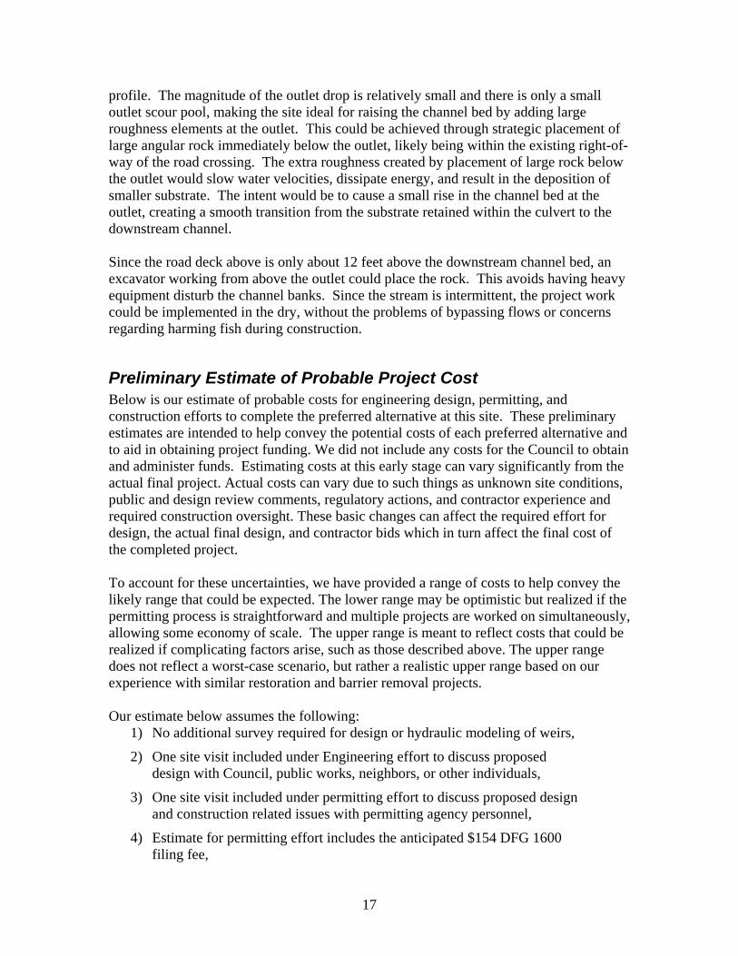
profile. The magnitude of the outlet drop is relatively small and there is only a small outlet scour pool, making the site ideal for raising the channel bed by adding large roughness elements at the outlet. This could be achieved through strategic placement of large angular rock immediately below the outlet, likely being within the existing right-of-way of the road crossing. The extra roughness created by placement of large rock below the outlet would slow water velocities, dissipate energy, and result in the deposition of smaller substrate. The intent would be to cause a small rise in the channel bed at the outlet, creating a smooth transition from the substrate retained within the culvert to the downstream channel. Since the road deck above is only about 12 feet above the downstream channel bed, an excavator working from above the outlet could place the rock. This avoids having heavy equipment disturb the channel banks. Since the stream is intermittent, the project work could be implemented in the dry, without the problems of bypassing flows or concerns regarding harming fish during construction.
Preliminary Estimate of Probable Project Cost Below is our estimate of probable costs for engineering design, permitting, and construction efforts to complete the preferred alternative at this site. These preliminary estimates are intended to help convey the potential costs of each preferred alternative and to aid in obtaining project funding. We did not include any costs for the Council to obtain and administer funds. Estimating costs at this early stage can vary significantly from the actual final project. Actual costs can vary due to such things as unknown site conditions, public and design review comments, regulatory actions, and contractor experience and required construction oversight. These basic changes can affect the required effort for design, the actual final design, and contractor bids which in turn affect the final cost of the completed project. To account for these uncertainties, we have provided a range of costs to help convey the likely range that could be expected. The lower range may be optimistic but realized if the permitting process is straightforward and multiple projects are worked on simultaneously, allowing some economy of scale. The upper range is meant to reflect costs that could be realized if complicating factors arise, such as those described above. The upper range does not reflect a worst-case scenario, but rather a realistic upper range based on our experience with similar restoration and barrier removal projects. Our estimate below assumes the following:
1) No additional survey required for design or hydraulic modeling of weirs,
2) One site visit included under Engineering effort to discuss proposed design with Council, public works, neighbors, or other individuals,
3) One site visit included under permitting effort to discuss proposed design and construction related issues with permitting agency personnel,
4) Estimate for permitting effort includes the anticipated $154 DFG 1600 filing fee,
17

5) Estimate for construction effort includes three days by engineer on site, likely the first three days of construction,
6) No water diversion will be necessary,
7) No traffic control necessary at this site.
Preliminary Estimate of Probable Project Costs For the Los Trancos Creek Fire Access Road Retrofit Alternative
Estimate Item: Item Estimate: Engineering Effort: this item includes hydrologic and hydraulic calculations and modeling, engineering design and drafting, cost estimates, one site visit to review the design with Council, property owners and/or agency personnel.
$5,000 - $7,000
Permitting Effort: this item includes time to research and complete DFG 1600 and ACOE RGP permit applications, limited biological and other general permitting research, permit filing fees, and a site visit to meet with regulatory personnel to explain the project design and anticipated construction methodology. This estimate does not include special surveys, special studies, CEQA, or other potential studies or permits that may arise.
$3,500 - $4,500
Construction Effort: this item includes limited construction inspection by the engineers, and contractor costs including materials and labor to construct the preferred alternative.
$8,000 - $10,000
Total Estimate of Probable Costs for Project $16,500 - $21,500
18
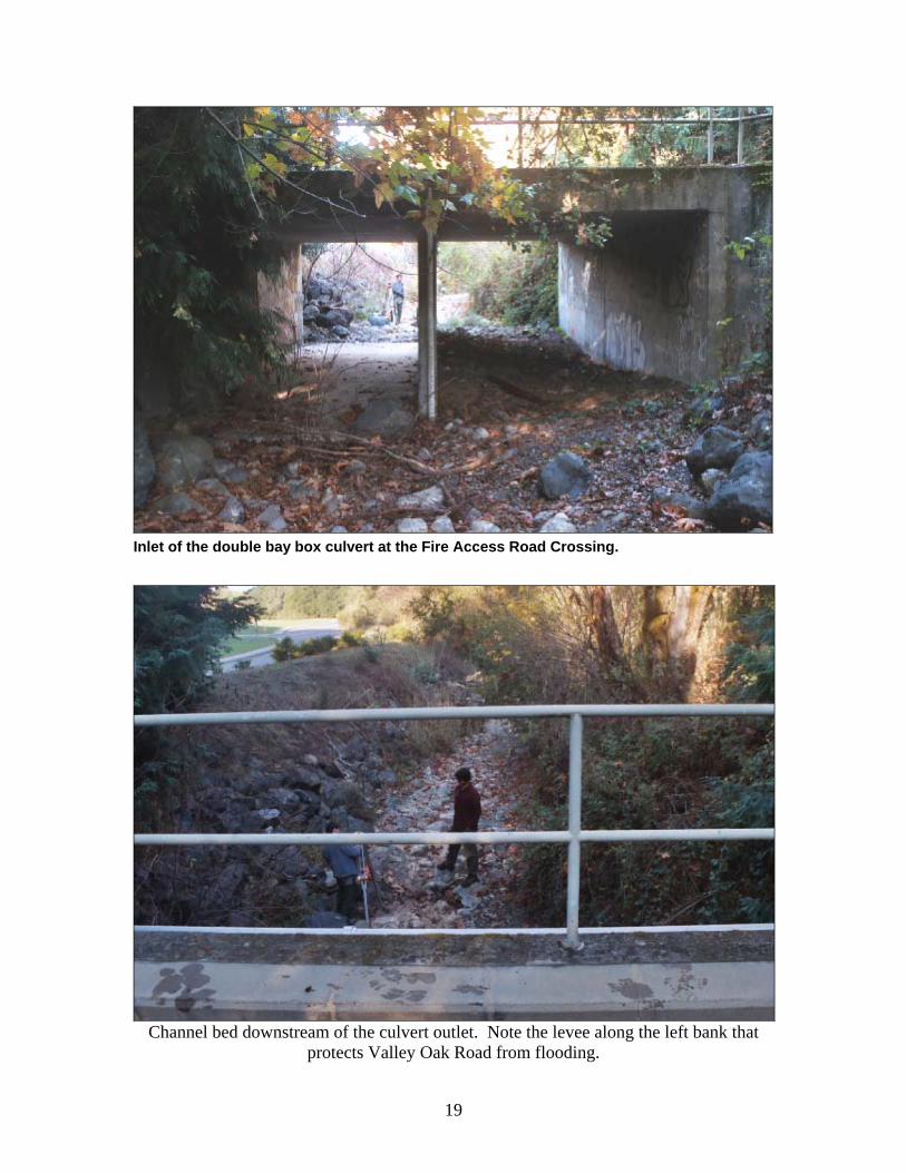
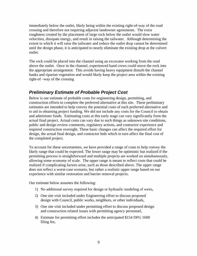
Inlet of the double bay box culvert at the Fire Access Road Crossing.
Channel bed downstream of the culvert outlet. Note the levee along the left bank that
protects Valley Oak Road from flooding.
19
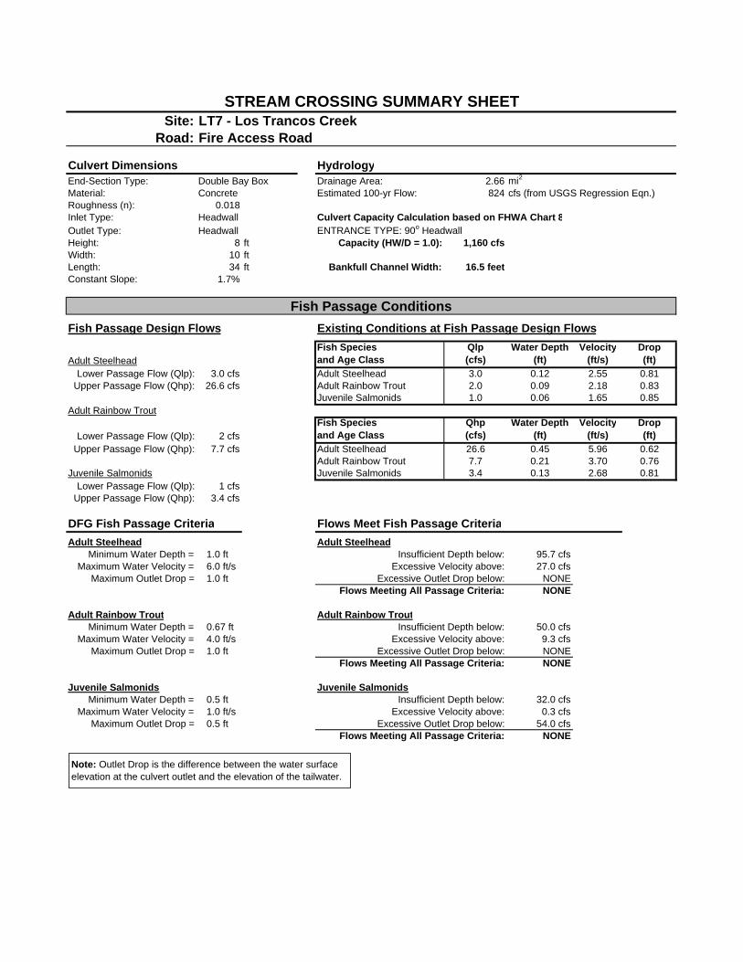
Site: LT7 - Los Trancos CreekRoad: Fire Access Road
Culvert Dimensions HydrologyEnd-Section Type: Double Bay Box Drainage Area: 2.66 mi2
Material: Concrete Estimated 100-yr Flow: 824 cfs (from USGS Regression Eqn.)Roughness (n): 0.018Inlet Type: Headwall Culvert Capacity Calculation based on FHWA Chart 8Outlet Type: Headwall ENTRANCE TYPE: 90o HeadwallHeight: 8 ft Capacity (HW/D = 1.0): 1,160 cfsWidth: 10 ftLength: 34 ft Bankfull Channel Width: 16.5 feetConstant Slope: 1.7%
Fish Passage Design Flows Existing Conditions at Fish Passage Design Flows
Adult SteelheadFish Speciesand Age Class
Qlp(cfs)
Water Depth(ft)
Velocity(ft/s)
Drop(ft)
Lower Passage Flow (Qlp): 3.0 cfs Adult Steelhead 3.0 0.12 2.55 0.81Upper Passage Flow (Qhp): 26.6 cfs Adult Rainbow Trout 2.0 0.09 2.18 0.83
Juvenile Salmonids 1.0 0.06 1.65 0.85Adult Rainbow Trout
Lower Passage Flow (Qlp): 2 cfsFish Speciesand Age Class
Qhp(cfs)
Water Depth(ft)
Velocity(ft/s)
Drop(ft)
Upper Passage Flow (Qhp): 7.7 cfs Adult Steelhead 26.6 0.45 5.96 0.62Adult Rainbow Trout 7.7 0.21 3.70 0.76
Juvenile Salmonids Juvenile Salmonids 3.4 0.13 2.68 0.81Lower Passage Flow (Qlp): 1 cfs
Upper Passage Flow (Qhp): 3.4 cfs
DFG Fish Passage Criteria Flows Meet Fish Passage CriteriaAdult Steelhead Adult Steelhead
Minimum Water Depth = 1.0 ft Insufficient Depth below: 95.7 cfsMaximum Water Velocity = 6.0 ft/s Excessive Velocity above: 27.0 cfs
Maximum Outlet Drop = 1.0 ft Excessive Outlet Drop below: NONEFlows Meeting All Passage Criteria: NONE
Adult Rainbow Trout Adult Rainbow TroutMinimum Water Depth = 0.67 ft Insufficient Depth below: 50.0 cfs
Maximum Water Velocity = 4.0 ft/s Excessive Velocity above: 9.3 cfsMaximum Outlet Drop = 1.0 ft Excessive Outlet Drop below: NONE
Flows Meeting All Passage Criteria: NONE
Juvenile Salmonids Juvenile SalmonidsMinimum Water Depth = 0.5 ft Insufficient Depth below: 32.0 cfs
Maximum Water Velocity = 1.0 ft/s Excessive Velocity above: 0.3 cfsMaximum Outlet Drop = 0.5 ft Excessive Outlet Drop below: 54.0 cfs
Flows Meeting All Passage Criteria: NONE
STREAM CROSSING SUMMARY SHEET
Fish Passage Conditions
Note: Outlet Drop is the difference between the water surface elevation at the culvert outlet and the elevation of the tailwater.
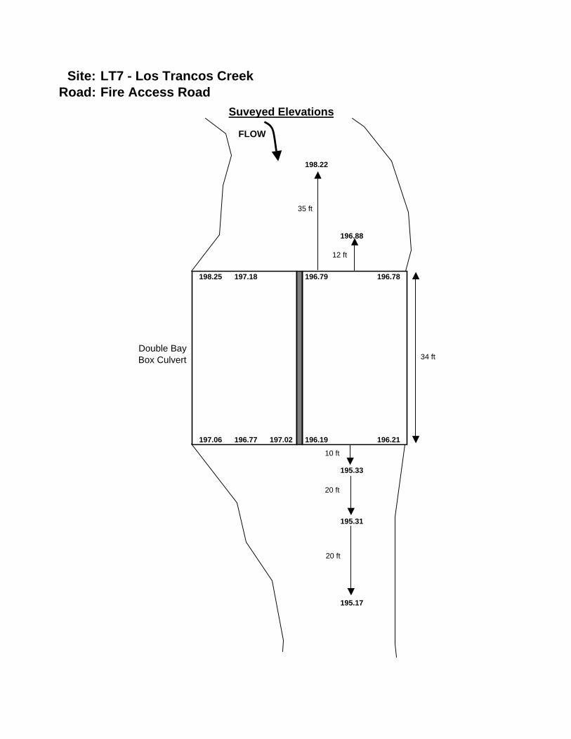
Site: LT7 - Los Trancos CreekRoad: Fire Access Road
Suveyed Elevations
198.22
196.88
198.25 197.18 196.79 196.78
197.06 196.77 197.02 196.19 196.21
195.33
195.31
195.17
20 ft
20 ft
10 ft
12 ft
35 ft
34 ftDouble BayBox Culvert
FLOW
Bear Gulch Creek at Fox Hollow Road
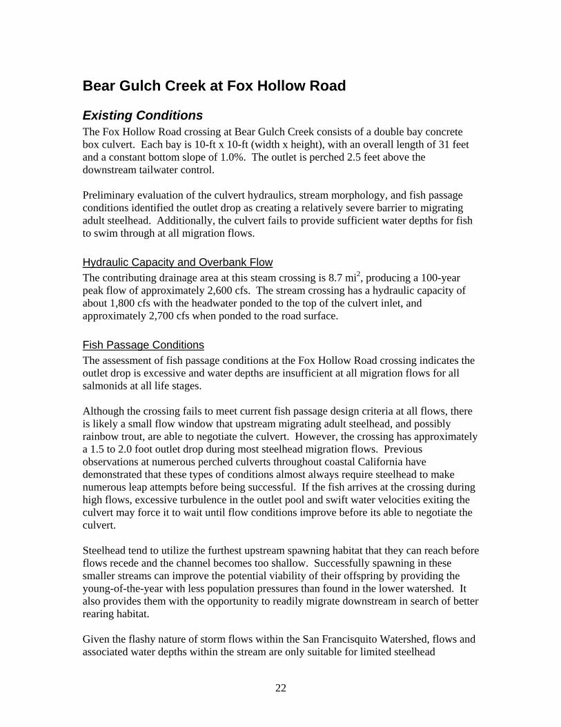
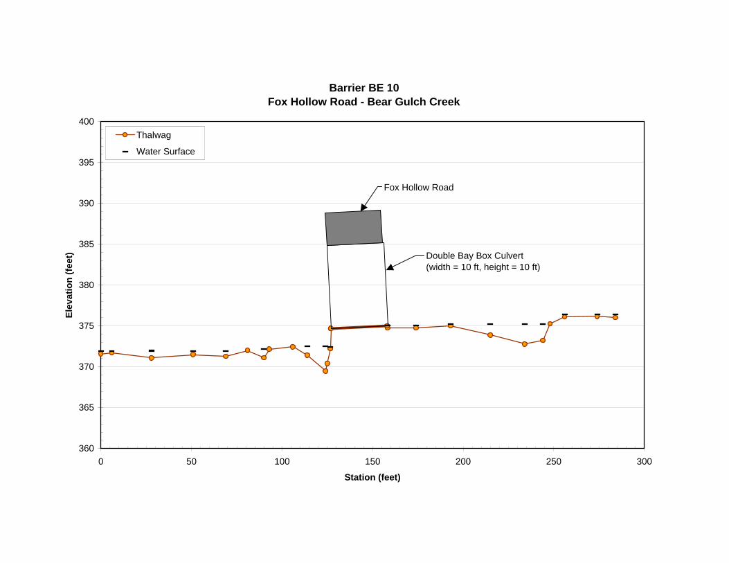
Existing Conditions The Fox Hollow Road crossing at Bear Gulch Creek consists of a double bay concrete box culvert. Each bay is 10-ft x 10-ft (width x height), with an overall length of 31 feet and a constant bottom slope of 1.0%. The outlet is perched 2.5 feet above the downstream tailwater control. Preliminary evaluation of the culvert hydraulics, stream morphology, and fish passage conditions identified the outlet drop as creating a relatively severe barrier to migrating adult steelhead. Additionally, the culvert fails to provide sufficient water depths for fish to swim through at all migration flows.
Hydraulic Capacity and Overbank Flow The contributing drainage area at this steam crossing is 8.7 mi2, producing a 100-year peak flow of approximately 2,600 cfs. The stream crossing has a hydraulic capacity of about 1,800 cfs with the headwater ponded to the top of the culvert inlet, and approximately 2,700 cfs when ponded to the road surface.
Fish Passage Conditions The assessment of fish passage conditions at the Fox Hollow Road crossing indicates the outlet drop is excessive and water depths are insufficient at all migration flows for all salmonids at all life stages. Although the crossing fails to meet current fish passage design criteria at all flows, there is likely a small flow window that upstream migrating adult steelhead, and possibly rainbow trout, are able to negotiate the culvert. However, the crossing has approximately a 1.5 to 2.0 foot outlet drop during most steelhead migration flows. Previous observations at numerous perched culverts throughout coastal California have demonstrated that these types of conditions almost always require steelhead to make numerous leap attempts before being successful. If the fish arrives at the crossing during high flows, excessive turbulence in the outlet pool and swift water velocities exiting the culvert may force it to wait until flow conditions improve before its able to negotiate the culvert. Steelhead tend to utilize the furthest upstream spawning habitat that they can reach before flows recede and the channel becomes too shallow. Successfully spawning in these smaller streams can improve the potential viability of their offspring by providing the young-of-the-year with less population pressures than found in the lower watershed. It also provides them with the opportunity to readily migrate downstream in search of better rearing habitat. Given the flashy nature of storm flows within the San Francisquito Watershed, flows and associated water depths within the stream are only suitable for limited steelhead
22
migration over a relatively short period of time. The Fox Hollow Road crossing is relatively low in the watershed. Any migrational delay imposed by this culvert can greatly reduce the time available for the fish to reach spawning grounds in the upper watershed. Such a delay could lead to the absence of spawning within portions of the upper watershed, which could reduce the viability of offspring.
Geomorphic Assessment of the Site The stream crossing is located on a migrating channel bend. Likely part of an effort to stop bank erosion along the outside portion of the bend, approximately 110 feet of the left channel bank immediately upstream of the culvert inlet has been armored with concrete . As a result, the channel has created a relatively deep thalwag along the armored left bank, undercutting the concrete. A large scour pool exists below the culvert outlet. The nearly 15-foot high banks along the left and right sides of the pool are extremely steep, and nearly vertical in some locations. The toes of these banks have been scoured and undermined by the 34-foot wide outlet pool, causing the banks to be relatively unstable. A portion of the right bank immediately below the culvert has been armored with large rock (appearing to be in the 3 to 4 ton range). The left bank and unarmored portion of the right bank appears to be held tenuously in place mostly by large roots. The left bank appears unstable and is actively retreating, as evidenced by the exposed soils and overhanging roots. Below the outlet pool both banks have been armored, which extends more than 100-feet downstream. The left bank consists of a vertical concrete retaining wall that appears to have been in place for some time. The right bank appears to have been recently armored with large rock-slope-protection (RSP), which extends 15 to 20 feet up the bank at roughly a 1:1 (H:V) slope. As a result, the downstream channel is highly confined and much narrower than the upstream channel. The downstream channel bed is flat and featureless, composed mostly of sand and small gravels. Examination of the retaining wall along the left banks suggests that the channel has incised approximately two feet since its construction, which corresponds with the perched culvert outlet. Given the shape, slope, and composition of the downstream channel, it appears downcutting is not currently active. During the site visit at baseflow conditions, we observed a backwatering of the channel extending more than 200 feet upstream, ending immediately below the outlet pool. The feature creating the backwater was not identified due to limited access. If the downstream grade controlling features remain unchanged the risk of future downcutting appears minimal. To improve our understanding of the downstream channel bed’s stability and to anticipate future channel adjustments, these grade-controlling features should be identified and characterized.
Considered Alternatives Several alternatives aimed at improving fish passage conditions were considered before a preferred alternative was selected. They include:
23
• Full replacement of the stream crossing structure with a crossing that maintains a natural streambed and banks throughout.
• Installation of four boulder jump-pool weirs to eliminate the outlet drop and backwater the culvert by raising the tailwater.
• Construction of a pool-chute fishway to eliminate the outlet drop.
• Construction of a “roughened channel” to raise the channel bed at the culvert outlet and backwater the culvert.
Full Replacement of Stream Crossing The existing crossing appears to be in relatively good condition and has sufficient hydraulic capacity. However, it is undersized relative to the upstream channel width, constricting the flows and producing excessively high outlet velocities. To ensure a replacement crossing provides free movement of all fish and other aquatic species, it should be designed based on the stream simulation concept. Stream simulation requires maintaining a natural channel bed and no interruption in the channel profile throughout the crossing. To achieve this, a primary design criteria requires the crossing width to be greater than the bankfull channel width. At this site, a replacement crossing would need to have a span of roughly 30 feet or more. There are only a limited number of options that could meet this requirement. They include options such as an extremely large open-bottom arch culvert on concrete footings, a wider box culvert similar to the existing structure, or a long-span bridge. The road surface is between 14 feet and 17 feet above the channel. To keep the bridge span from being too long, the site would almost certainly necessitate construction of vertical bridge abutments. All three options (open bottom arch culvert, a larger box culvert, and bridge) are very costly to construct and would not address some of the issues at the site. Based on previous experience, if the difference in grade between the upstream and downstream channel was not addressed, a large headcut and resulting channel incision would migrate upstream following the culvert replacement. The affected portions of the upstream channel could experience bank instability and a decrease in the quality of aquatic habitat. The downstream channel would likely receive large pulses of sediment released from the headcutting, which could impair downstream habitat and potentially reduce channel capacity. Installing stable grade control to prevent the headcutting is extremely challenging in streams as large as this one, and may not be successful. Such a headcut could result in a new barrier upstream of the replaced culvert. Another difficult issue concerning full replacement at the Fox Hollow Road crossing would be providing temporary access for residents and emergency vehicles. There are a number of homes that are only accessible via this stream crossing. Replacing the crossing is a large project that would take several months to complete. During construction a temporary crossing would need to be provided. The only likely location suitable for a temporary crossing appears to be upstream of the existing culvert, which
24
would also be the primary access point for heavy equipment entering the channel. Providing these temporary access routes would appear to require cutting numerous large redwood trees that grow on both sides of the stream and create healthy riparian canopy. We do not recommend cutting down numerous large redwood trees to make a temporary crossing possible. Full replacement of the existing stream crossing would be extremely difficult and costly, impacting well established riparian vegetation and potentially leading to extensive channel headcutting and more bank instability. Given that other design alternatives could improve fish passage while avoiding such potential impacts, the option of full replacement was not selected as the preferred alternative. However, if significant road modifications are planned in the future, full replacement of the crossing should be considered.
Boulder Jump-Pool Weirs A common method of improving passage conditions at perched culvert outlets in smaller watersheds has been to construct a series of boulder weirs to raise the water surface, reducing or eliminating the outlet drop. The CDFG and NOAA Fisheries guidelines prescribe no more than a one-foot drop between boulder weirs. When using one-foot drops, these types of weirs are typically spaced 30-feet apart, for an average slope of 3.3% between weirs. This spacing provides enough pool volume to dissipate energy associated with the drop, which helps reduce the potential for weir failure. To eliminate the drop at the Fox Hollow Road crossing and backwater the outlet to increase depth in the culvert would require at least four boulder weirs. At the typical 30 foot spacing, the lower weir would need to be positioned approximately 120-feet downstream of the culvert outlet. The project would require providing equipment access to at least 150 feet of the downstream channel, necessitating the cooperation of adjoining property owners. Boulder weirs are typically U-shaped with the apex facing upstream. They should be constructed using two layers of very large angular rock. The lower layer of boulders, commonly referred to as footer rocks, is placed deep enough to avoid undermining from scour. Each weir is an independent structure, but relies on the next downstream weir to control the drop height. When a critical boulder within a weir moves during high flows a cascading failure often ensues, leading to the failure of remaining upstream weirs. Some designs call for cabling the boulders together to reduce the risk of movement. However, experience shows that cabling does not add much to the structural integrity of the weir. Boulders are often still able to move enough to cause the weir to fail even when cabled. The result can be a failed weir with boulders still attached to each other or a failed weir with frayed cables perturbing from boulders in the channel. Biologists have noted that pools formed between boulder weirs can create good rearing habitat. However, population studies from Washington State Department of Fish and Wildlife found that when multiple pools are constructed below a culvert, only the two upper most pools appear to provide good habitat. Salmonids rely heavily on downstream insect drift to deliver food, so fish rearing in the upper pools tend to take all of the insect drift, preventing it from reaching the lower pools.
25
Use of multiple boulder jump-pool weirs have fallen into disfavor among many practitioners within the stream restoration community. Their shortcomings include wide spacing requirements that limit their application to low gradient streams, their inherent instability, and limited habitat value associated with having multiple adjoining pools. For these reasons, boulder jump-pool weirs were not selected as a preferred alternative.
Pool and Chute Fishway The instability of boulder weirs can be overcome by using other construction materials. Fishways constructed of concrete or metal sheet pile is an effective way of providing salmonids access to perched culverts. There are numerous types of fishways, but only three types are appropriate for use at culvert outlets. They are roughened chutes (denil or Alaskan steeppass ladders), pool and weir fishways, and pool and chute fishways. Roughened chutes use turbulence to slow water and create depth. However, the turbulence is too high to allow passage of smaller salmonids. They are also the most susceptible to debris plugging. Pool and weir fishways can provide passage for adult and juvenile salmonids over a relatively limited range of flows. Water plunges over each weir and into a pool. The weir spacing is typically a minimum of 10-feet and drops for juvenile salmonid passage are recommended to be 0.5-feet, but are sometimes increased to 0.75-feet. Using the larger of the two drop heights, a pool and weir fishway constructed at the outlet of the Fox Hollow Road culvert would need to be 50-feet in length. However, the low and high adult fish passage flows for this site are 3 cfs and 87 cfs, respectfully. It is unlikely that a pool and weir fishway could be designed to accommodate passage over such a wide range of flows. Accommodating the wide range of fish passage design flows at this site, along with the desire to minimize the length of the project area, makes a concrete pool and chute fishway the most applicable type of fishway for the site. It functions as a hybrid, with the center of the fishway functioning as a chute and the edges functioning as a pool and weir fishway. It is also designed steeper than the traditional pool and weir fishway, resulting in a shorter structure. Although still susceptible to debris plugging, pool and chute fishways are better than the other fishways at passing large debris. They can be constructed using 6 to 8-foot spacing between weirs with 0.75-foot drops. For the project site, the pool and chute fishway would need five weirs and extend approximately 35 feet downstream of the culvert outlet. This would place the end of the fishway just below the existing outlet pool, at the beginning of the RSP along the right bank. The upstream end of the fishway could be designed to backwater the culvert, improving depth conditions. Some of the main disadvantages associated with pool and chute fishway are aesthetics, maintenance (sedimentation between weirs, debris plugging), and construction cost. Additionally, they fail to address passage of other aquatic species besides salmonids. For
26
27
these reasons, this alternative was less preferable than using a roughened channel approach.
Preferred Alternative
Constructing a Roughened Channel leading up to Culvert Outlet The natural-looking roughened channel design is an innovative approach to addressing differences in grade. Although use of this design technique is relatively new in the United States, it has been used extensively in Europe. Sometimes referred to as a rock-ramp, the technique involves building-up and oversteepening the channel with various sized rock. To ensure its stability and to keep conditions acceptable for fish passage, a roughened channel is composed of a mixture of various sediment sizes, including large rock that increases roughness and fine grain sediments to prevent flows from going subsurface. The recommended maximum steepness of a roughened channel is 5.0%. To increase depth within the culvert, the roughened channel could be built-up enough to backwater the culvert outlet and provide at least 0.5-feet of depth throughout. In addition, a sill (wooden or metal) could be mounted on the outlet to aid in backwatering the culvert and protect the exposed face of the rock from being dislodged from debris flowing downstream. Keeping the sill low will minimize the projects effect on the hydraulic capacity of the crossing. The roughened channel, placed at a 5% slope, would need to be approximately 65-feet in length. This would place the downstream end of the project near the beginning edge of the concrete retaining wall along the left bank. As with any of the considered alternatives, constructing a roughened channel will require the cooperation of the two adjacent downstream landowners. In particular, the landowner along the left bank would be most impacted by the project because the only suitable access point for heavy equipment appears to be along the left bank adjacent to the outlet pool. This bank, which appears unstable due to visual signs of active erosion, would need to be laid back to allow equipment to ramp down to the site. This would result in the loss of several smaller trees. However, once the project is completed the bank would be stabilized with a mix of hard armoring on the lower bank and bioengineering techniques on the upper bank. The right upper bank would not be accessed or disturbed. Only work from the channel would occur on the right bank and would include buttressing the toe with rock like the other side. This would ultimately help protect the owners’ property by reducing the potential of future bank erosion. Some of the main disadvantages associated with the roughened channel are the large quantity of rock used, its related construction costs, and the potential for winnowing of smaller substrate leading to low flows going subsurface. Maintenance should not be a problem as the roughened channel has no weirs or other in-stream structures to trap debris. Advantages include the aesthetics of a more natural channel (rock and vegetation), lower maintenance, passage of other aquatic species besides salmonids, energy dissipation of high velocities exiting the culvert, and increased bank stability. Given the high cost associated with this option, it may be appropriate to install the outlet sill first as an interim measure as additional funds are sought for design and construction
28
of the roughened channel. Although the sill will not reduce the jump height, it would help improve passage conditions by increasing water depths within the culvert.
Preliminary Estimate of Probable Project Cost Below is our estimate of probable costs for engineering design, permitting, and construction efforts to complete the preferred alternative at this site. These preliminary estimates are intended to help convey the potential costs of each preferred alternative and to aid in obtaining project funding. We did not include any costs for the Council to obtain and administer funds. Estimating costs at this early stage can vary significantly from the actual final project. Actual costs can vary due to such things as unknown site conditions, public and design review comments, regulatory actions, and contractor experience and required construction oversight. These basic changes can affect the required effort for design, the actual final design, and contractor bids which in turn affect the final cost of the completed project. To account for these uncertainties, we have provided a range of costs to help convey the likely range that could be expected. The lower range may be optimistic but realized if the permitting process is straightforward and multiple projects are worked on simultaneously, allowing some economy of scale. The upper range is meant to reflect costs that could be realized if complicating factors arise, such as those described above. The upper range does not reflect a worst-case scenario, but rather a realistic upper range based on our experience with similar restoration and barrier removal projects. Our estimate below assumes the following:
1) Topographic site survey required for design and hydraulic modeling,
2) One site visit included under Engineering effort to discuss proposed design with Council, public works, neighbors, or other individuals,
3) One site visit included under permitting effort to discuss proposed design and construction related issues with permitting agency personnel,
4) Estimate for permitting effort includes anticipated $772.75 DFG 1600 filing fee,
5) Estimate for construction effort includes four weeks by engineer on site,
6) Significant effort for water diversion will be necessary,
7) Traffic control only requires construction signage and no flag persons.
29
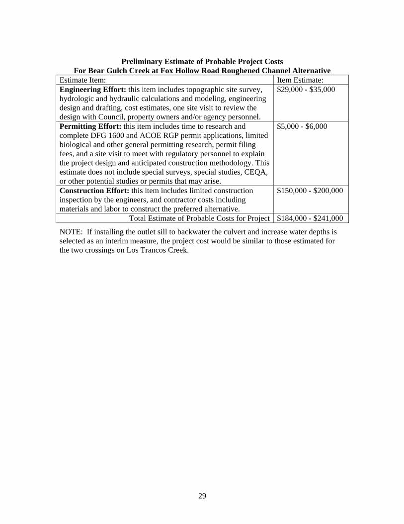
Preliminary Estimate of Probable Project Costs
For Bear Gulch Creek at Fox Hollow Road Roughened Channel Alternative Estimate Item: Item Estimate: Engineering Effort: this item includes topographic site survey, hydrologic and hydraulic calculations and modeling, engineering design and drafting, cost estimates, one site visit to review the design with Council, property owners and/or agency personnel.
$29,000 - $35,000
Permitting Effort: this item includes time to research and complete DFG 1600 and ACOE RGP permit applications, limited biological and other general permitting research, permit filing fees, and a site visit to meet with regulatory personnel to explain the project design and anticipated construction methodology. This estimate does not include special surveys, special studies, CEQA, or other potential studies or permits that may arise.
$5,000 - $6,000
Construction Effort: this item includes limited construction inspection by the engineers, and contractor costs including materials and labor to construct the preferred alternative.
$150,000 - $200,000
Total Estimate of Probable Costs for Project $184,000 - $241,000
NOTE: If installing the outlet sill to backwater the culvert and increase water depths is selected as an interim measure, the project cost would be similar to those estimated for the two crossings on Los Trancos Creek.
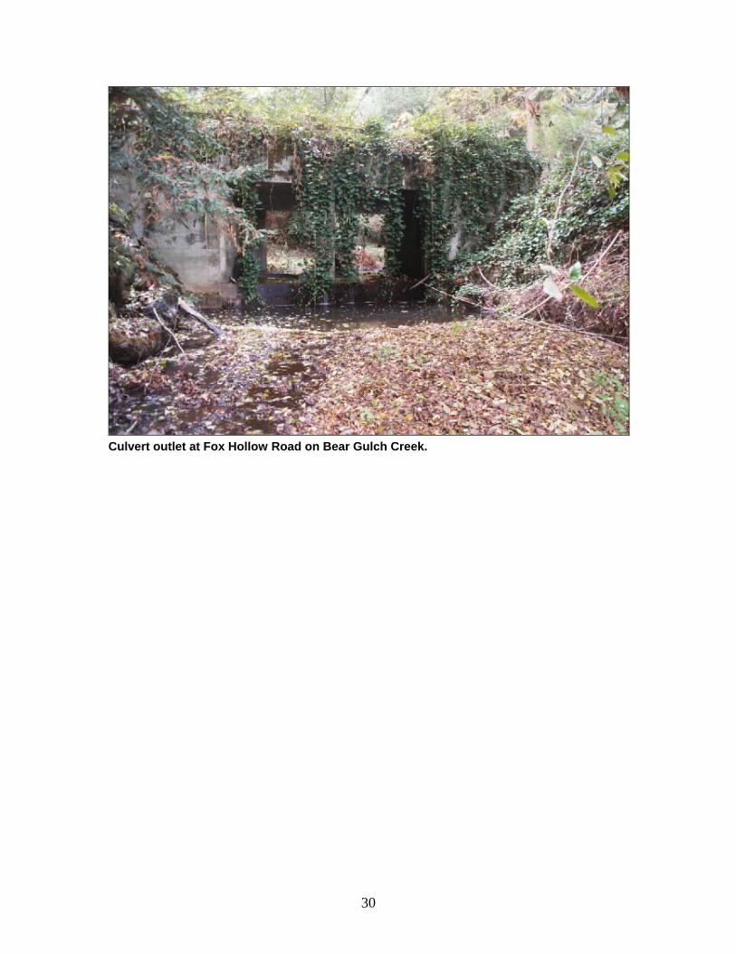
Culvert outlet at Fox Hollow Road on Bear Gulch Creek.
30
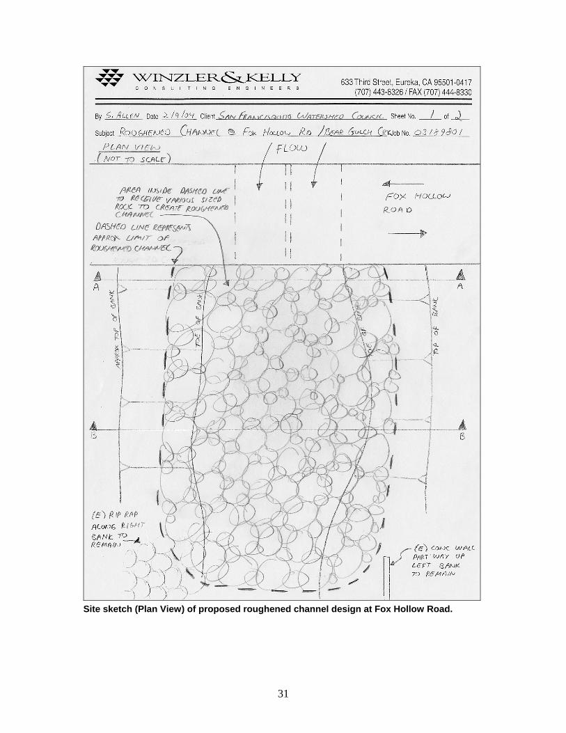
Site sketch (Plan View) of proposed roughened channel design at Fox Hollow Road.
31
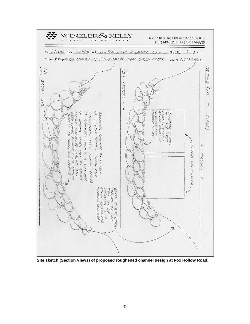
Site sketch (Section Views) of proposed roughened channel design at Fox Hollow Road.
32
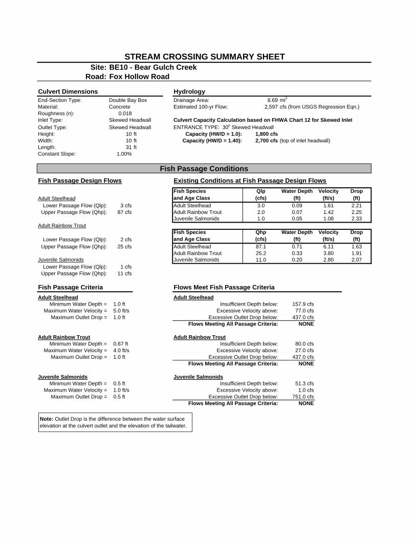
Site: BE10 - Bear Gulch CreekRoad: Fox Hollow Road
Culvert Dimensions HydrologyEnd-Section Type: Double Bay Box Drainage Area: 8.69 mi2
Material: Concrete Estimated 100-yr Flow: 2,597 cfs (from USGS Regression Eqn.)Roughness (n): 0.018Inlet Type: Skewed Headwall Culvert Capacity Calculation based on FHWA Chart 12 for Skewed InletOutlet Type: Skewed Headwall ENTRANCE TYPE: 30o Skewed HeadwallHeight: 10 ft Capacity (HW/D = 1.0): 1,800 cfsWidth: 10 ft Capacity (HW/D = 1.40): 2,700 cfs (top of inlet headwall)Length: 31 ftConstant Slope: 1.00%
Fish Passage Design Flows Existing Conditions at Fish Passage Design Flows
Adult SteelheadFish Speciesand Age Class
Qlp(cfs)
Water Depth(ft)
Velocity(ft/s)
Drop(ft)
Lower Passage Flow (Qlp): 3 cfs Adult Steelhead 3.0 0.09 1.61 2.21Upper Passage Flow (Qhp): 87 cfs Adult Rainbow Trout 2.0 0.07 1.42 2.25
Juvenile Salmonids 1.0 0.05 1.08 2.33Adult Rainbow Trout
Lower Passage Flow (Qlp): 2 cfsFish Speciesand Age Class
Qhp(cfs)
Water Depth(ft)
Velocity(ft/s)
Drop(ft)
Upper Passage Flow (Qhp): 25 cfs Adult Steelhead 87.1 0.71 6.11 1.63Adult Rainbow Trout 25.2 0.33 3.80 1.91
Juvenile Salmonids Juvenile Salmonids 11.0 0.20 2.80 2.07Lower Passage Flow (Qlp): 1 cfs
Upper Passage Flow (Qhp): 11 cfs
Fish Passage Criteria Flows Meet Fish Passage CriteriaAdult Steelhead Adult Steelhead
Minimum Water Depth = 1.0 ft Insufficient Depth below: 157.9 cfsMaximum Water Velocity = 5.0 ft/s Excessive Velocity above: 77.0 cfs
Maximum Outlet Drop = 1.0 ft Excessive Outlet Drop below: 437.0 cfsFlows Meeting All Passage Criteria: NONE
Adult Rainbow Trout Adult Rainbow TroutMinimum Water Depth = 0.67 ft Insufficient Depth below: 80.0 cfs
Maximum Water Velocity = 4.0 ft/s Excessive Velocity above: 27.0 cfsMaximum Outlet Drop = 1.0 ft Excessive Outlet Drop below: 437.0 cfs
Flows Meeting All Passage Criteria: NONE
Juvenile Salmonids Juvenile SalmonidsMinimum Water Depth = 0.5 ft Insufficient Depth below: 51.3 cfs
Maximum Water Velocity = 1.0 ft/s Excessive Velocity above: 1.0 cfsMaximum Outlet Drop = 0.5 ft Excessive Outlet Drop below: 751.0 cfs
Flows Meeting All Passage Criteria: NONE
STREAM CROSSING SUMMARY SHEET
Fish Passage Conditions
Note: Outlet Drop is the difference between the water surface elevation at the culvert outlet and the elevation of the tailwater.
Barrier BE 10Fox Hollow Road - Bear Gulch Creek
360
365
370
375
380
385
390
395
400
0 50 100 150 200 250 300
Station (feet)
Elev
atio
n (fe
et)
Thalwag
Water Surface
Double Bay Box Culvert(width = 10 ft, height = 10 ft)
Fox Hollow Road
McGarvey Gulch at Huddard Park Trail Crossing
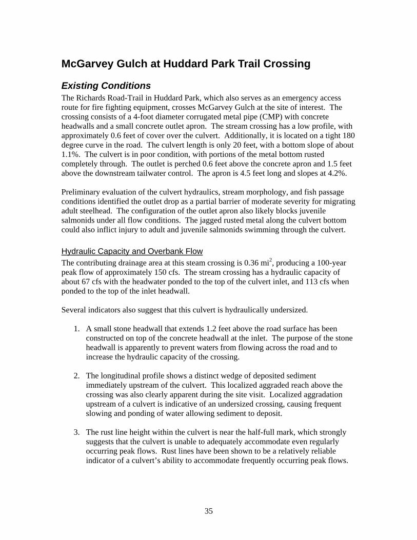
Existing Conditions The Richards Road-Trail in Huddard Park, which also serves as an emergency access route for fire fighting equipment, crosses McGarvey Gulch at the site of interest. The crossing consists of a 4-foot diameter corrugated metal pipe (CMP) with concrete headwalls and a small concrete outlet apron. The stream crossing has a low profile, with approximately 0.6 feet of cover over the culvert. Additionally, it is located on a tight 180 degree curve in the road. The culvert length is only 20 feet, with a bottom slope of about 1.1%. The culvert is in poor condition, with portions of the metal bottom rusted completely through. The outlet is perched 0.6 feet above the concrete apron and 1.5 feet above the downstream tailwater control. The apron is 4.5 feet long and slopes at 4.2%. Preliminary evaluation of the culvert hydraulics, stream morphology, and fish passage conditions identified the outlet drop as a partial barrier of moderate severity for migrating adult steelhead. The configuration of the outlet apron also likely blocks juvenile salmonids under all flow conditions. The jagged rusted metal along the culvert bottom could also inflict injury to adult and juvenile salmonids swimming through the culvert.
Hydraulic Capacity and Overbank Flow The contributing drainage area at this steam crossing is 0.36 mi2, producing a 100-year peak flow of approximately 150 cfs. The stream crossing has a hydraulic capacity of about 67 cfs with the headwater ponded to the top of the culvert inlet, and 113 cfs when ponded to the top of the inlet headwall. Several indicators also suggest that this culvert is hydraulically undersized.
1. A small stone headwall that extends 1.2 feet above the road surface has been constructed on top of the concrete headwall at the inlet. The purpose of the stone headwall is apparently to prevent waters from flowing across the road and to increase the hydraulic capacity of the crossing.
2. The longitudinal profile shows a distinct wedge of deposited sediment immediately upstream of the culvert. This localized aggraded reach above the crossing was also clearly apparent during the site visit. Localized aggradation upstream of a culvert is indicative of an undersized crossing, causing frequent slowing and ponding of water allowing sediment to deposit.
3. The rust line height within the culvert is near the half-full mark, which strongly suggests that the culvert is unable to adequately accommodate even regularly occurring peak flows. Rust lines have been shown to be a relatively reliable indicator of a culvert’s ability to accommodate frequently occurring peak flows.
35
Fish Passage Conditions The assessment of fish passage conditions at the Huddard Park trail crossing indicates the outlet drop is excessive at all migration flows for all salmonids. Additionally, depths over the outlet apron are extremely shallow and the drop from the outlet onto the apron makes it difficult for a fish to swim into the culvert. Although the crossing fails to meet current fish passage design criteria at all flows, there is likely a range of flows that upstream migrating adult steelhead and rainbow trout are able to negotiate the culvert. Given the small drainage area associated with the crossing, steelhead likely only spawn in this portion of the stream during high flows that typically persist for short periods. Any delay could greatly limit the distance a steelhead swims upstream of the crossing before flows recede and the channel becomes too shallow. An existing short and steep (>10%) channel grade that forms the transition between the aggraded channel reach and the culvert inlet, referred to as the “inlet drop”. The local upstream aggradation and associated inlet drop can create a partial barrier. Unlike drop over large rock or wood embedded into the channel, the inlet drop produces shallow water depths uncharacteristic of depths found in the adjacent channel. Observations have documented salmon and steelhead often having difficulty, both physically and behaviorally, swimming through the shallow depths with higher velocities occurring across these inlet drops. Although only a partial barrier to adults, the crossings outlet apron likely blocks access to upstream overwintering habitat for all young-of-the-year salmonids.
Geomorphic Assessment of the Site The assessed channel reach has an average slope of roughly 3.5% and is predominately a step-pool channel type. The forcing features creating the pools are predominately small boulders, with some pools created by embedded large wood. Approximately 200 feet downstream, the channel type changes as bedrock outcrops and extremely large colluvium control streambed elevations. The channel profile appears to be generally stable, showing no signs of recent downcutting. The numerous stable grade-controlling features located downstream of the crossing suggest there is little risk of future downcutting. Aggradation that stretches 150 feet upstream of the crossing is a localized feature resulting from backwater effects created by the undersized culvert. At the upstream end of the aggraded reach there is a low water crossing used by hikers and horses. Although minor in nature, the low water crossing contributes fine sediment to the channel. The frequent use of the crossing has disturbed the stream banks and caused the channel bed to locally widen. Bankfull channel widths were measured in a channel segment located upstream of the aggraded reach above the influence of the culvert. This relatively straight channel segment contained well defined bankfull indicators and a nearly constant bankfull width of 7.5-feet.
36
Considered Alternatives Several alternatives aimed at improving fish passage conditions were considered before a preferred alternative was selected. Due to the culvert’s extremely poor condition and inadequate hydraulic capacity, only alternatives consisting of full crossing replacement were considered. They include:
• Prefabricated bridge.
• Low-profile open-bottom arch set on precast concrete footings.
• Stream simulation design using a corrugated metal pipe arch culvert.
Prefabricated Bridge A prefabricated bridge was considered for the site. Designed for standard Caltrans HS20 loading, it would be able to accommodate loading requirements associated with providing access for fire trucks. To provide a 9-foot wide channel below the bridge (120% of bankfull width) and accommodate the 100-year peak flow the bridge span would need to be approximately 25-feet. However, the crossing is located on a tight turn. To accommodate fire truck turning radius requirements, it would need to be a two-lane bridge. If selected as a preferred alterative, the extra width required will add substantial cost to the overall project. Since other alternatives offer similar environmental benefits for a lower cost, the prefabricated bridge option was not selected as the preferred alternative.
Low-Profile Open-Bottom Arch A structural steel-plated low-profile arch culvert would be able to meet the needed width requirements while accommodating the roads low profile. The culvert would need to have a width of at least 9 feet. The arch could be on precast concrete footings, placed well below the line of anticipated scour. The road profile may need to be raised approximately 0.5-feet to maintain sufficient cover over the culvert while providing adequate hydraulic capacity. The primary disadvantage associated with this option is the construction time needed to place footings and assembling the culvert. Unlike other culvert types, structural steel-plated arches must be assembled in-channel. An extended in-channel construction period would lengthen the time in which the trail crossing would be closed to the public and emergency vehicles. The materials and labor costs associated with using a low-profile arch would also be more than using a corrugated metal pipe arch.
37
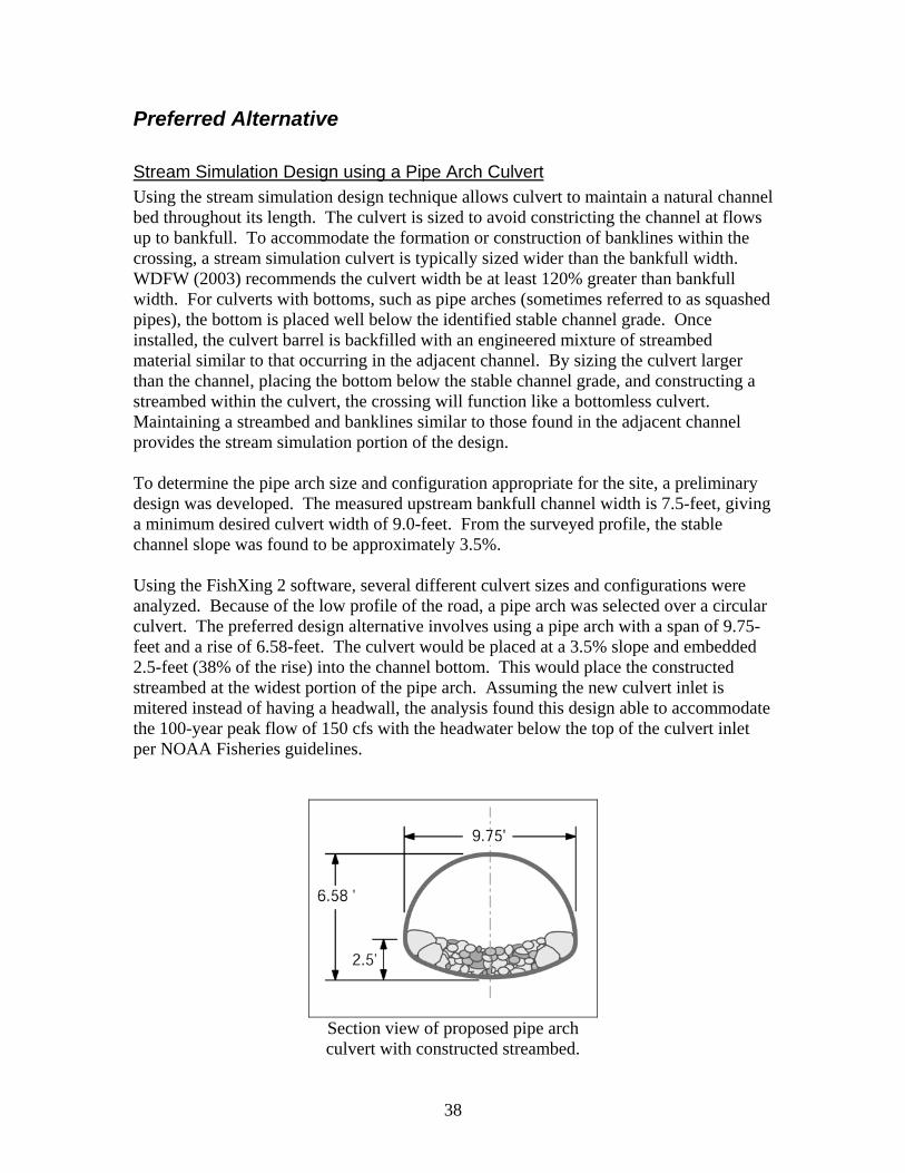
Preferred Alternative
Stream Simulation Design using a Pipe Arch Culvert Using the stream simulation design technique allows culvert to maintain a natural channel bed throughout its length. The culvert is sized to avoid constricting the channel at flows up to bankfull. To accommodate the formation or construction of banklines within the crossing, a stream simulation culvert is typically sized wider than the bankfull width. WDFW (2003) recommends the culvert width be at least 120% greater than bankfull width. For culverts with bottoms, such as pipe arches (sometimes referred to as squashed pipes), the bottom is placed well below the identified stable channel grade. Once installed, the culvert barrel is backfilled with an engineered mixture of streambed material similar to that occurring in the adjacent channel. By sizing the culvert larger than the channel, placing the bottom below the stable channel grade, and constructing a streambed within the culvert, the crossing will function like a bottomless culvert. Maintaining a streambed and banklines similar to those found in the adjacent channel provides the stream simulation portion of the design. To determine the pipe arch size and configuration appropriate for the site, a preliminary design was developed. The measured upstream bankfull channel width is 7.5-feet, giving a minimum desired culvert width of 9.0-feet. From the surveyed profile, the stable channel slope was found to be approximately 3.5%. Using the FishXing 2 software, several different culvert sizes and configurations were analyzed. Because of the low profile of the road, a pipe arch was selected over a circular culvert. The preferred design alternative involves using a pipe arch with a span of 9.75-feet and a rise of 6.58-feet. The culvert would be placed at a 3.5% slope and embedded 2.5-feet (38% of the rise) into the channel bottom. This would place the constructed streambed at the widest portion of the pipe arch. Assuming the new culvert inlet is mitered instead of having a headwall, the analysis found this design able to accommodate the 100-year peak flow of 150 cfs with the headwater below the top of the culvert inlet per NOAA Fisheries guidelines.
Section view of proposed pipe arch culvert with constructed streambed.
38
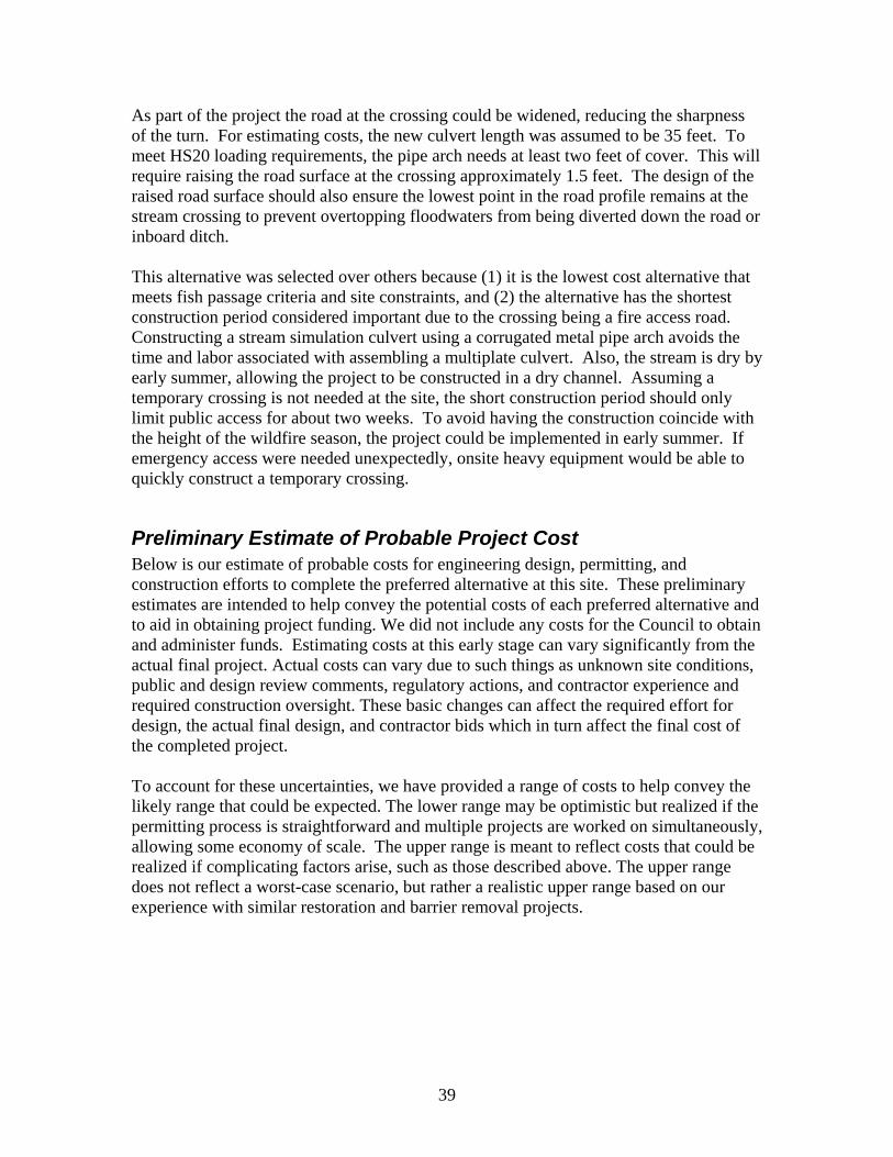
As part of the project the road at the crossing could be widened, reducing the sharpness of the turn. For estimating costs, the new culvert length was assumed to be 35 feet. To meet HS20 loading requirements, the pipe arch needs at least two feet of cover. This will require raising the road surface at the crossing approximately 1.5 feet. The design of the raised road surface should also ensure the lowest point in the road profile remains at the stream crossing to prevent overtopping floodwaters from being diverted down the road or inboard ditch. This alternative was selected over others because (1) it is the lowest cost alternative that meets fish passage criteria and site constraints, and (2) the alternative has the shortest construction period considered important due to the crossing being a fire access road. Constructing a stream simulation culvert using a corrugated metal pipe arch avoids the time and labor associated with assembling a multiplate culvert. Also, the stream is dry by early summer, allowing the project to be constructed in a dry channel. Assuming a temporary crossing is not needed at the site, the short construction period should only limit public access for about two weeks. To avoid having the construction coincide with the height of the wildfire season, the project could be implemented in early summer. If emergency access were needed unexpectedly, onsite heavy equipment would be able to quickly construct a temporary crossing.
Preliminary Estimate of Probable Project Cost Below is our estimate of probable costs for engineering design, permitting, and construction efforts to complete the preferred alternative at this site. These preliminary estimates are intended to help convey the potential costs of each preferred alternative and to aid in obtaining project funding. We did not include any costs for the Council to obtain and administer funds. Estimating costs at this early stage can vary significantly from the actual final project. Actual costs can vary due to such things as unknown site conditions, public and design review comments, regulatory actions, and contractor experience and required construction oversight. These basic changes can affect the required effort for design, the actual final design, and contractor bids which in turn affect the final cost of the completed project. To account for these uncertainties, we have provided a range of costs to help convey the likely range that could be expected. The lower range may be optimistic but realized if the permitting process is straightforward and multiple projects are worked on simultaneously, allowing some economy of scale. The upper range is meant to reflect costs that could be realized if complicating factors arise, such as those described above. The upper range does not reflect a worst-case scenario, but rather a realistic upper range based on our experience with similar restoration and barrier removal projects.
39

Our estimate below assumes the following:
1) Topographic site survey required for design and hydraulic modeling,
2) One site visit included under Engineering effort to discuss proposed design with Council, public works, Fire Marshal, or other individuals,
3) One site visit included under permitting effort to discuss proposed design and construction related issues with permitting agency personnel,
4) Estimate for permitting effort includes anticipated $772.75 DFG 1600 filing fee,
5) Estimate for construction effort includes one week by engineer on site,
6) No water diversion will be necessary,
7) No Traffic control will be required.
Preliminary Estimate of Probable Project Costs For McGarvey Gulch Culvert Replacement Alternative
Estimate Item: Item Estimate: Engineering Effort: this item includes hydrologic and hydraulic calculations and modeling, engineering design and drafting, cost estimates, one site visit to review the design with Council, property owners and/or agency personnel.
$10,000 - $15,000
Permitting Effort: this item includes time to research and complete DFG 1600 and ACOE RGP permit applications, limited biological and other general permitting research, permit filing fees, and a site visit to meet with regulatory personnel to explain the project design and anticipated construction methodology. This estimate does not include special surveys, special studies, CEQA, or other potential studies or permits that may arise.
$4,000 - $5,000
Construction Effort: this item includes limited construction inspection by the engineers, and contractor costs including materials and labor to construct the preferred alternative.
$45,000 - $60,000
Total Estimate of Probable Costs for Project $59,000 - $80,000
40
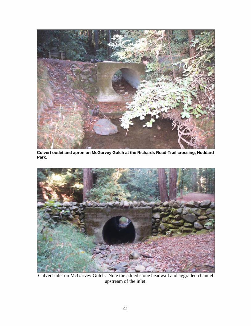
Culvert outlet and apron on McGarvey Gulch at the Richards Road-Trail crossing, Huddard Park.
Culvert inlet on McGarvey Gulch. Note the added stone headwall and aggraded channel
upstream of the inlet.
41
Site: MG2 - McGarvey GulchRoad: Huddart Park Trail Crossing
Culvert Dimensions HydrologyEnd-Section Type: Circular Drainage Area: 0.36 mi2
Material: CMP Estimated 100-yr Flow: 149 cfs (from USGS Regression Eqn.)Roughness (n): 0.024Inlet Type: Concrete Headwall Culvert Capacity Calculations from CulvertMasterOutlet Type: Headwall and Apron ENTRANCE TYPE: HeadwallDiameter 4.0 ft Capacity (HW/D = 1.0): 67 cfs (Outlet Control)CMP Length: 20 ft Capacity (HW/D = 1.45*): 113 cfs (Inlet Control)CMP Slope: 1.05% *HW at top of inlet headwallDrop from outlet invert to apron: 0.64 ftApron Length: 4.5 ftApron Width: 8.0 ftApron Slope: 4.20%
Fish Passage Design Flows Existing Conditions at Fish Passage Design FlowsEstimated 2-year Flow (Q-2yr):
(from USGS Regression Eqn.)16 cfs
Fish Speciesand Age Class
Qlp(cfs)
Water Depth(ft)
Velocity(ft/s)
Drop2
(ft)
Adult Steelhead Adult Steelhead 3.0 0.53 3.04 1.72Lower Passage Flow (Qlp): 3 cfs Adult Rainbow Trout 2.0 0.44 2.69 1.72
Upper Passage Flow (Qhp)1: 8.0 cfs Juvenile Salmonids 1.0 0.31 2.19 1.66
Adult Rainbow TroutFish Speciesand Age Class
Qhp(cfs)
Water Depth(ft)
Velocity(ft/s)
Drop2
(ft)Lower Passage Flow (Qlp): 2 cfs Adult Steelhead 8.0 0.85 4.07 1.89
Upper Passage Flow (Qhp)1: 4.8 cfs Adult Rainbow Trout 4.8 0.66 3.50 1.82Juvenile Salmonids 1.6 0.39 2.52 1.69
Juvenile SalmonidsLower Passage Flow (Qlp): 1 cfs
Upper Passage Flow (Qhp)1: 1.6 cfs
Fish Passage Criteria Flows Meet Fish Passage CriteriaAdult Steelhead Adult Steelhead
Minimum Water Depth = 1.0 ft Insufficient Depth below: 11.0 cfsMaximum Water Velocity = 6.0 ft/s Excessive Velocity above: 32.0 cfs
Maximum Outlet Drop = 1.0 ft Excessive Outlet Drop below: NONEFlows Meeting All Passage Criteria: NONE
Adult Rainbow Trout Adult Rainbow TroutMinimum Water Depth = 0.67 ft Insufficient Depth below: 5.0 cfs
Maximum Water Velocity = 4.0 ft/s Excessive Velocity above: 7.5 cfsMaximum Outlet Drop = 1.0 ft Excessive Outlet Drop below: NONE
Flows Meeting All Passage Criteria: NONE
Juvenile Salmonids Juvenile SalmonidsMinimum Water Depth = 0.5 ft Insufficient Depth below: 2.7 cfs
Maximum Water Velocity = 1.0 ft/s Excessive Velocity above: 0.1 cfsMaximum Outlet Drop = 0.5 ft Excessive Outlet Drop below: NONE
Flows Meeting All Passage Criteria: NONE
STREAM CROSSING SUMMARY SHEET
Fish Passage Conditions
Note 2: Outlet Drop is the difference between the water surface elevation at the culvert outlet and the elevation of the tailwater, without accounting for the outlet apron. Tailwater submerges downstream apron edge at 14.5 cfs
Note 1: Due to small drainage area, upper passage flows were estimated using DFG/ NOAA Fisheries alternative method: Qhp (adult steelhead) = 50% of Q-2yr Qhp (adult rainbow trout) = 30% of Q-2yr Qhp (juvenile salmonids) = 10% of Q-2yr
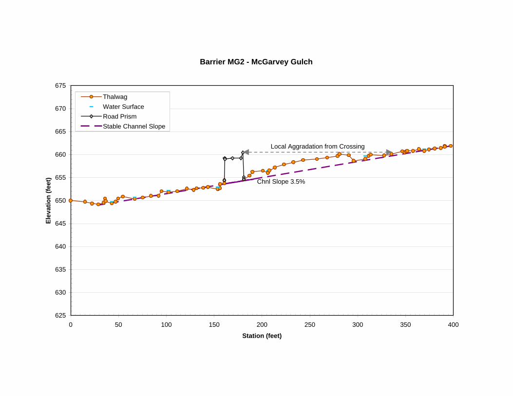
Barrier MG2 - McGarvey Gulch
625
630
635
640
645
650
655
660
665
670
675
0 50 100 150 200 250 300 350 400
Station (feet)
Elev
atio
n (fe
et)
ThalwagWater SurfaceRoad PrismStable Channel Slope
Chnl Slope 3.5%
Local Aggradation from Crossing

Appendix A Hydrologic Calculations
44
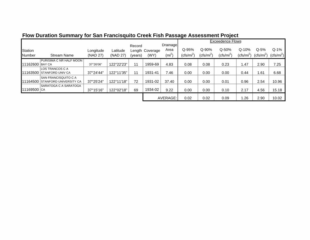
Flow Duration Summary for San Francisquito Creek Fish Passage Assessment ProjectExceedence Flows
Station Number Stream Name
Longitude(NAD 27)
Latitude(NAD 27)
Record Length (years)
Coverage (WY)
Drainage Area(mi2)
Q-95%(cfs/mi2)
Q-90%(cfs/mi2)
Q-50%(cfs/mi2)
Q-10%(cfs/mi2)
Q-5%(cfs/mi2)
Q-1%(cfs/mi2)
11162600PURISIMA C NR HALF MOON BAY CA 37°26'06" 122°22'23" 11 1959-69 4.83 0.08 0.08 0.23 1.47 2.90 7.25
11163500LOS TRANCOS C A STANFORD UNIV CA 37°24'44" 122°11'35" 11 1931-41 7.46 0.00 0.00 0.00 0.44 1.61 6.68
11164500SAN FRANCISQUITO C A STANFORD UNIVERSITY CA 37°25'24" 122°11'18" 72 1931-02 37.40 0.00 0.00 0.01 0.96 2.54 10.96
11169500SARATOGA C A SARATOGA CA 37°15'16" 122°02'18" 69 1934-02 9.22 0.00 0.00 0.10 2.17 4.56 15.18
AVERAGE: 0.02 0.02 0.09 1.26 2.90 10.02
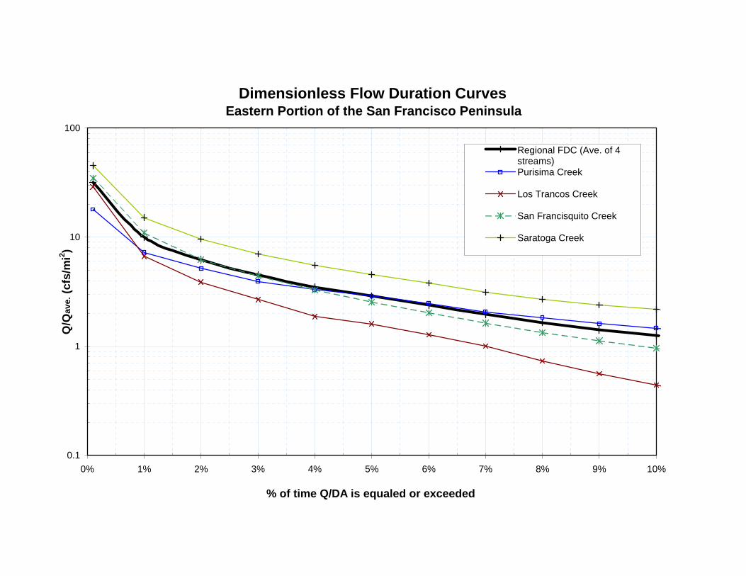
Dimensionless Flow Duration Curves Eastern Portion of the San Francisco Peninsula
0.1
1
10
100
0% 1% 2% 3% 4% 5% 6% 7% 8% 9% 10%
% of time Q/DA is equaled or exceeded
Q/Q
ave.
(cfs
/mi2 )
Regional FDC (Ave. of 4streams)Purisima Creek
Los Trancos Creek
San Francisquito Creek
Saratoga Creek
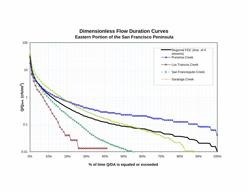
Dimensionless Flow Duration Curves Eastern Portion of the San Francisco Peninsula
0.01
0.1
1
10
100
0% 10% 20% 30% 40% 50% 60% 70% 80% 90% 100%
% of time Q/DA is equaled or exceeded
Q/Q
ave.
(cfs
/mi2 )
Regional FDC (Ave. of 4streams)Purisima Creek
Los Trancos Creek
San Francisquito Creek
Saratoga Creek
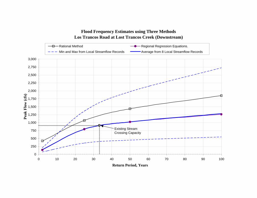
Flood Frequency Estimates using Three Methods Los Trancos Road at Lost Trancos Creek (Downstream)
0
250
500
750
1,000
1,250
1,500
1,750
2,000
2,250
2,500
2,750
3,000
0 10 20 30 40 50 60 70 80 90 100
Return Period, Years
Peak
Flo
w (c
fs)
Rational Method Regional Regression Equations.
Min and Max from Local Streamflow Records Average from 8 Local Streamflow Records
Existing Stream Crossing Capacity
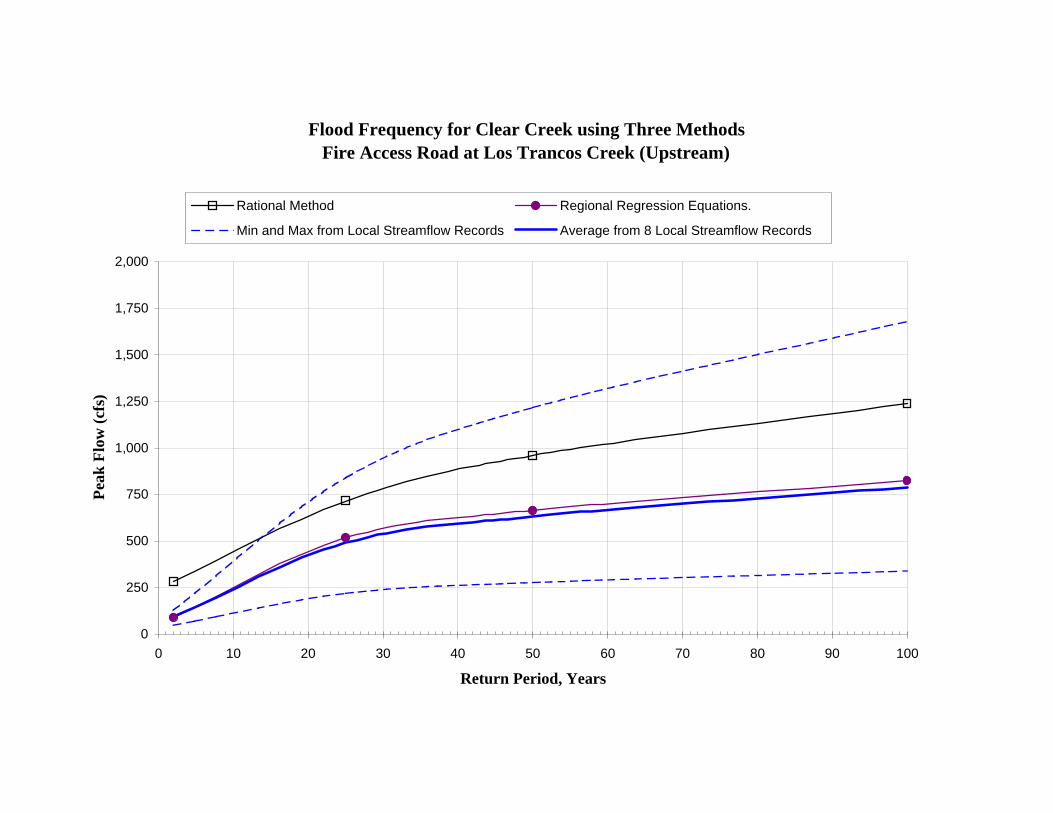
Flood Frequency for Clear Creek using Three Methods Fire Access Road at Los Trancos Creek (Upstream)
0
250
500
750
1,000
1,250
1,500
1,750
2,000
0 10 20 30 40 50 60 70 80 90 100
Return Period, Years
Peak
Flo
w (c
fs)
Rational Method Regional Regression Equations.
Min and Max from Local Streamflow Records Average from 8 Local Streamflow Records
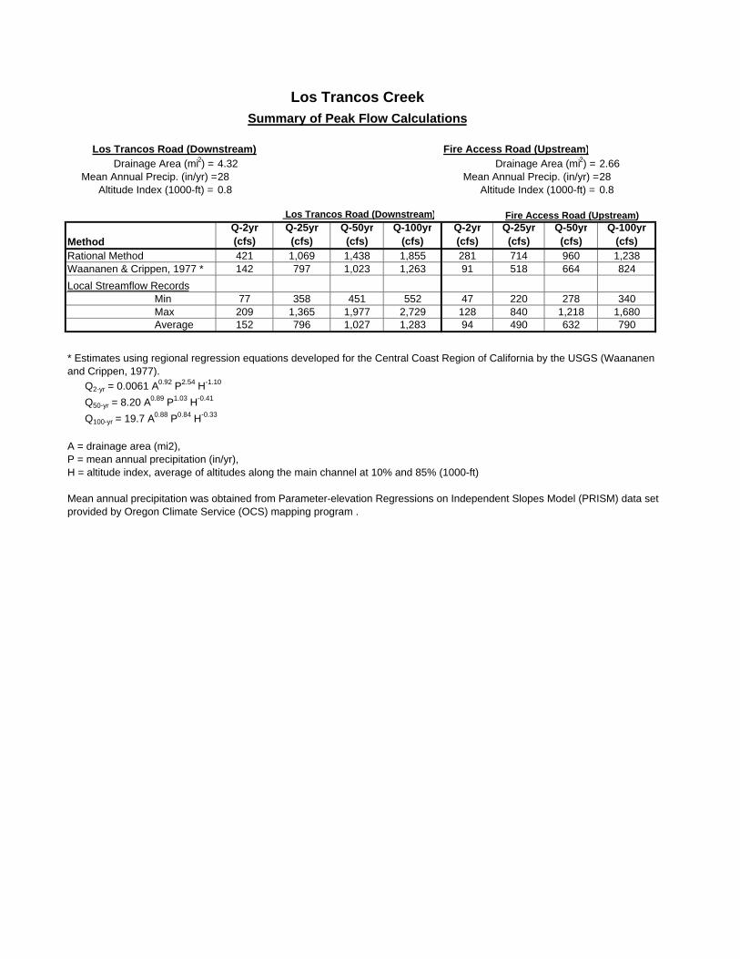
Los Trancos CreekSummary of Peak Flow Calculations
Los Trancos Road (Downstream) . Fire Access Road (Upstream)Drainage Area (mi2) = 4.32 Drainage Area (mi2) = 2.66
Mean Annual Precip. (in/yr) =28 Mean Annual Precip. (in/yr) =28Altitude Index (1000-ft) = 0.8 Altitude Index (1000-ft) = 0.8
Los Trancos Road (Downstream) Fire Access Road (Upstream)
MethodQ-2yr(cfs)
Q-25yr(cfs)
Q-50yr(cfs)
Q-100yr(cfs)
Q-2yr(cfs)
Q-25yr(cfs)
Q-50yr(cfs)
Q-100yr(cfs)
Rational Method 421 1,069 1,438 1,855 281 714 960 1,238Waananen & Crippen, 1977 * 142 797 1,023 1,263 91 518 664 824Local Streamflow Records
Min 77 358 451 552 47 220 278 340Max 209 1,365 1,977 2,729 128 840 1,218 1,680Average 152 796 1,027 1,283 94 490 632 790
* Estimates using regional regression equations developed for the Central Coast Region of California by the USGS (Waananen and Crippen, 1977). Q2-yr = 0.0061 A0.92 P2.54 H-1.10
Q50-yr = 8.20 A0.89 P1.03 H-0.41
Q100-yr = 19.7 A0.88 P0.84 H-0.33
A = drainage area (mi2),P = mean annual precipitation (in/yr), H = altitude index, average of altitudes along the main channel at 10% and 85% (1000-ft)
Mean annual precipitation was obtained from Parameter-elevation Regressions on Independent Slopes Model (PRISM) data set provided by Oregon Climate Service (OCS) mapping program .
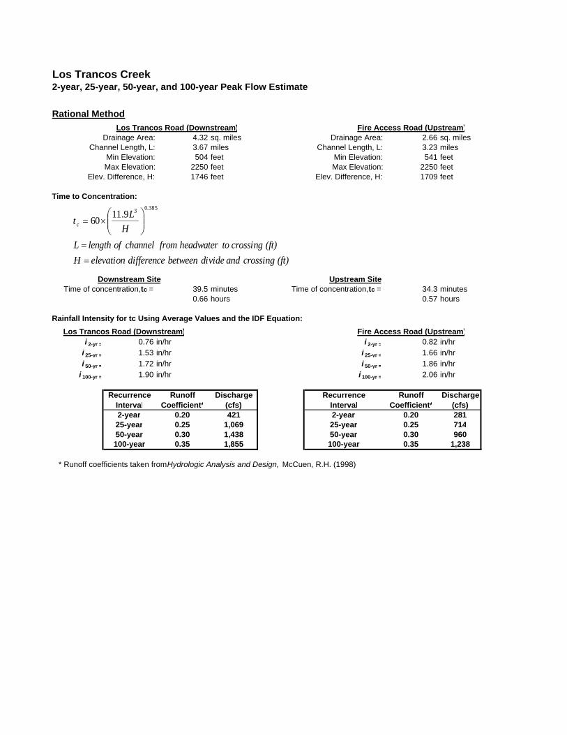
Los Trancos Creek2-year, 25-year, 50-year, and 100-year Peak Flow Estimate
Rational MethodLos Trancos Road (Downstream) . Fire Access Road (Upstream)
Drainage Area: 4.32 sq. miles Drainage Area: 2.66 sq. milesChannel Length, L: 3.67 miles Channel Length, L: 3.23 miles
Min Elevation: 504 feet Min Elevation: 541 feetMax Elevation: 2250 feet Max Elevation: 2250 feet
Elev. Difference, H: 1746 feet Elev. Difference, H: 1709 feet
Time to Concentration:
Downstream Site Upstream SiteTime of concentration, tc = 39.5 minutes Time of concentration, tc = 34.3 minutes
0.66 hours 0.57 hours
Rainfall Intensity for tc Using Average Values and the IDF Equation:Los Trancos Road (Downstream) . Fire Access Road (Upstream)
i 2-yr = 0.76 in/hr i 2-yr = 0.82 in/hri 25-yr = 1.53 in/hr i 25-yr = 1.66 in/hri 50-yr = 1.72 in/hr i 50-yr = 1.86 in/hr
i 100-yr = 1.90 in/hr i 100-yr = 2.06 in/hr
RecurrenceInterval
Runoff Coefficient*
Discharge (cfs)
RecurrenceInterval
Runoff Coefficient*
Discharge (cfs)
2-year 0.20 421 2-year 0.20 28125-year 0.25 1,069 25-year 0.25 71450-year 0.30 1,438 50-year 0.30 960100-year 0.35 1,855 100-year 0.35 1,238
* Runoff coefficients taken from Hydrologic Analysis and Design, McCuen, R.H. (1998)
(ft) crossing and divide between difference elevation H(ft) crossing to headwater from channel of length L
HLtc
==
⎟⎟⎠
⎞⎜⎜⎝
⎛×=
385.039.1160
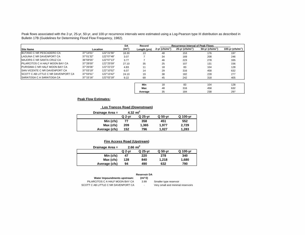
DA Record Recurrence Interval of Peak Flows Site Name (mi2) Length (yrs) 2-yr (cfs/mi2) 25-yr (cfs/mi2) 50-yr (cfs/mi2) 100-yr (cfs/mi2)BUTANO C NR PESCADERO CA 37°14'01" 122°21'56" 18.30 13 48 153 176 197LAGUNA C NR DAVENPORT CA 37°01'32" 122°07'48" 3.07 7 34 169 208 246MAJORS C NR SANTA CRUZ CA 36°59'55" 122°07'13" 3.77 7 46 223 278 335PILARCITOS C A HALF MOON BAY CA 37°28'00" 122°25'59" 27.10 35 25 107 131 156PURISIMA C NR HALF MOON BAY CA 37°26'06" 122°22'23" 4.83 11 18 83 104 128SAN VICENTE C NR DAVENPORT CA 37°03'19" 122°10'52" 6.07 14 29 316 458 632SCOTT C AB LITTLE C NR DAVENPORT CA 37°03'51" 122°13'42" 24.10 19 38 182 228 277SARATOGA C A SARATOGA CA 37°15'16" 122°02'18" 9.22 69 45 242 318 405
Min 18 83 104 128Max 48 316 458 632
Average 35 184 238 297
Peak Flow Estimates:
Los Trancos Road (Downstream)Drainage Area = 4.32 mi2
Q 2-yr Q 25-yr Q 50-yr Q 100-yrMin (cfs) 77 358 451 552Max (cfs) 209 1,365 1,977 2,729
Average (cfs) 152 796 1,027 1,283
Fire Access Road (Upstream)
Drainage Area = 2.66 mi2Q 2-yr Q 25-yr Q 50-yr Q 100-yr
Min (cfs) 47 220 278 340Max (cfs) 128 840 1,218 1,680
Average (cfs) 94 490 632 790
Water Impoundments upstream:Reservoir DA
(mi^2)PILARCITOS C A HALF MOON BAY CA 3.99 Smaller type reservoir
SCOTT C AB LITTLE C NR DAVENPORT CA - Very small and minimal reservoirs
Peak flows associated with the 2-yr, 25-yr, 50-yr, and 100-yr recurrence intervals were estimated using a Log-Pearson type III distribution as described in Bulletin 17B (Guidelines for Determining Flood Flow Frequency, 1982).
Location
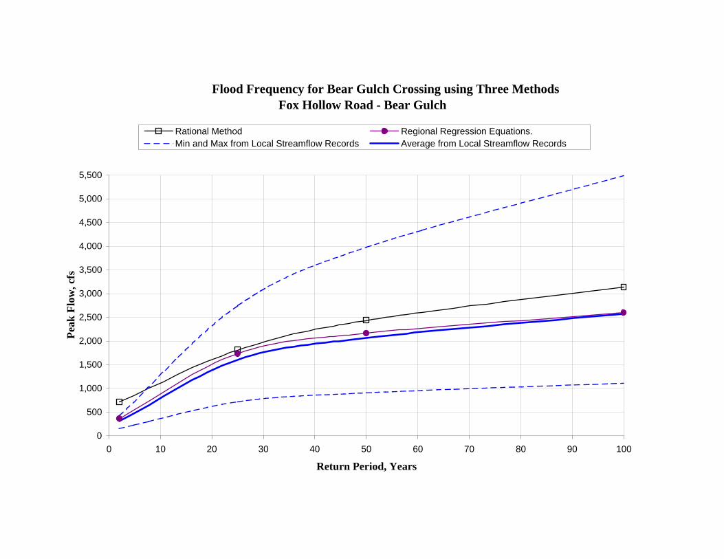
Flood Frequency for Bear Gulch Crossing using Three Methods Fox Hollow Road - Bear Gulch
0
500
1,000
1,500
2,000
2,500
3,000
3,500
4,000
4,500
5,000
5,500
0 10 20 30 40 50 60 70 80 90 100
Return Period, Years
Peak
Flo
w, c
fs
Rational Method Regional Regression Equations.Min and Max from Local Streamflow Records Average from Local Streamflow Records
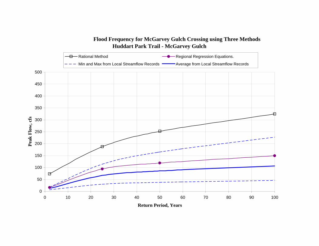
Flood Frequency for McGarvey Gulch Crossing using Three Methods Huddart Park Trail - McGarvey Gulch
0
50
100
150
200
250
300
350
400
450
500
0 10 20 30 40 50 60 70 80 90 100
Return Period, Years
Peak
Flo
w, c
fs
Rational Method Regional Regression Equations.
Min and Max from Local Streamflow Records Average from Local Streamflow Records

Bear Gulch Creek WatershedSummary of Peak Flow Calculations
Fox Hollow Road - Bear Gulch Creek Huddart Park Trail - McGarvey GulchDrainage Area (mi2) = 8.69 Drainage Area (mi2) = 0.36
Mean Annual Precip. (in/yr) =36 Mean Annual Precip. (in/yr) =36Altitude Index (1000-ft) = 1.1 Altitude Index (1000-ft) = 1.3
Fox Hollow Road - Bear Gulch Creek Huddart Park Trail - McGarvey Gulch
MethodQ-2yr(cfs)
Q-25yr(cfs)
Q-50yr(cfs)
Q-100yr(cfs)
Q-2yr(cfs)
Q-25yr(cfs)
Q-50yr(cfs)
Q-100yr(cfs)
Rational Method 714 1,812 2,436 3,143 74 187 252 324Waananen & Crippen, 1977 * 360 1,737 2,166 2,597 16 94 119 149Local Streamflow Records
Min 155 719 908 1,110 6 30 38 46Max 419 2,745 3,978 5,489 17 114 165 227Average 307 1,601 2,065 2,580 13 66 86 107
* Estimates using regional regression equations developed for the Central Coast Region of California by the USGS (Waananen and Crippen, 1977). Q2-yr = 0.0061 A0.92 P2.54 H-1.10
Q50-yr = 8.20 A0.89 P1.03 H-0.41
Q100-yr = 19.7 A0.88 P0.84 H-0.33
A = drainage area (mi2),P = mean annual precipitation (in/yr), H = altitude index, average of altitudes along the main channel at 10% and 85% (1000-ft)
Mean annual precipitation was obtained from Parameter-elevation Regressions on Independent Slopes Model (PRISM) data set provided by Oregon Climate Service (OCS) mapping program .
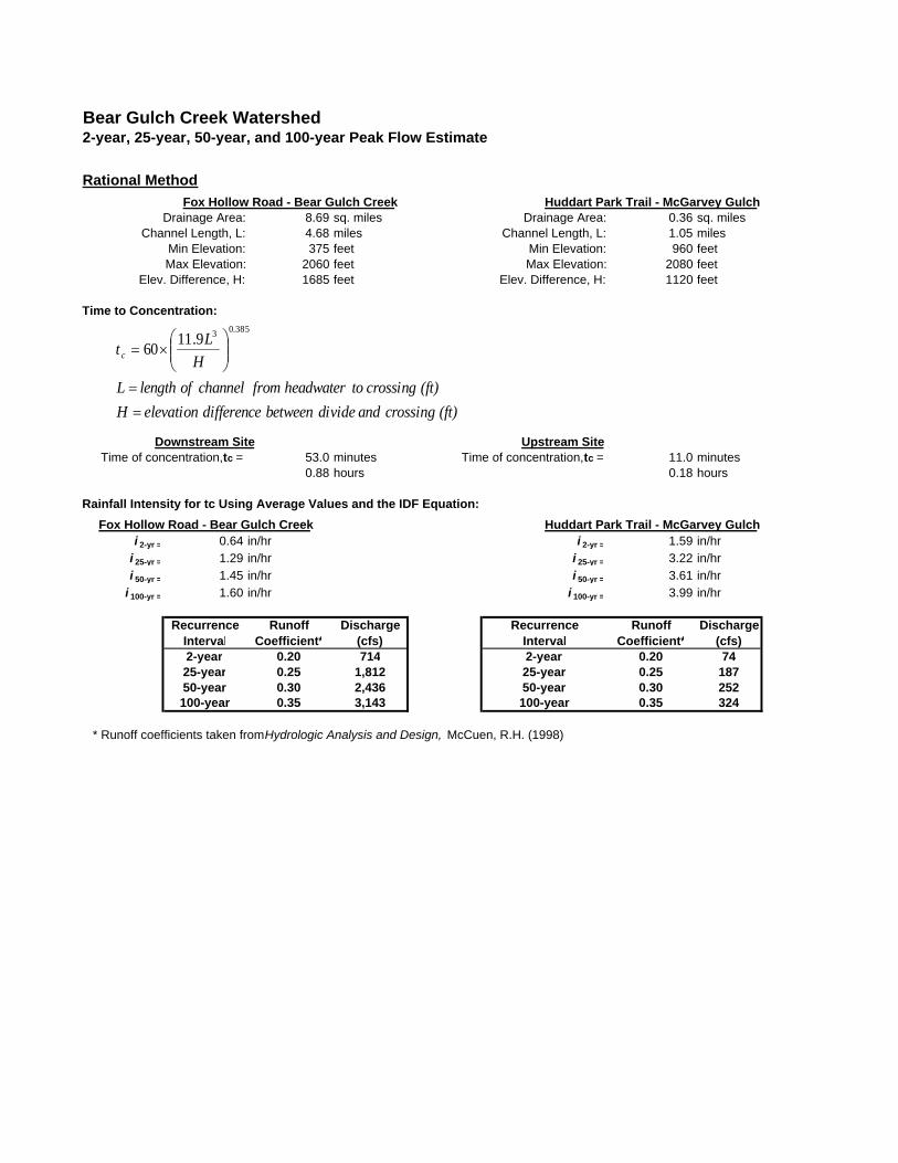
Bear Gulch Creek Watershed2-year, 25-year, 50-year, and 100-year Peak Flow Estimate
Rational MethodFox Hollow Road - Bear Gulch Creek Huddart Park Trail - McGarvey Gulch
Drainage Area: 8.69 sq. miles Drainage Area: 0.36 sq. milesChannel Length, L: 4.68 miles Channel Length, L: 1.05 miles
Min Elevation: 375 feet Min Elevation: 960 feetMax Elevation: 2060 feet Max Elevation: 2080 feet
Elev. Difference, H: 1685 feet Elev. Difference, H: 1120 feet
Time to Concentration:
Downstream Site Upstream SiteTime of concentration, tc = 53.0 minutes Time of concentration, tc = 11.0 minutes
0.88 hours 0.18 hours
Rainfall Intensity for tc Using Average Values and the IDF Equation:Fox Hollow Road - Bear Gulch Creek Huddart Park Trail - McGarvey Gulch
i 2-yr = 0.64 in/hr i 2-yr = 1.59 in/hri 25-yr = 1.29 in/hr i 25-yr = 3.22 in/hri 50-yr = 1.45 in/hr i 50-yr = 3.61 in/hr
i 100-yr = 1.60 in/hr i 100-yr = 3.99 in/hr
RecurrenceInterval
Runoff Coefficient*
Discharge (cfs)
RecurrenceInterval
Runoff Coefficient*
Discharge (cfs)
2-year 0.20 714 2-year 0.20 7425-year 0.25 1,812 25-year 0.25 18750-year 0.30 2,436 50-year 0.30 252100-year 0.35 3,143 100-year 0.35 324
* Runoff coefficients taken from Hydrologic Analysis and Design, McCuen, R.H. (1998)
(ft) crossing and divide between difference elevation H(ft) crossing to headwater from channel of length L
HLtc
==
⎟⎟⎠
⎞⎜⎜⎝
⎛×=
385.039.1160
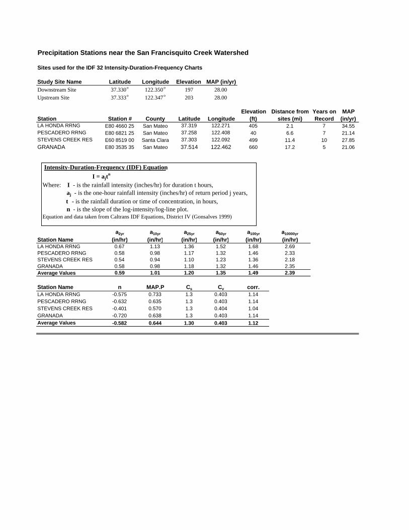
Precipitation Stations near the San Francisquito Creek Watershed
Sites used for the IDF 32 Intensity-Duration-Frequency Charts
Study Site Name Latitude Longitude Elevation MAP (in/yr)Downstream Site 37.330o 122.350o 197 28.00Upstream Site 37.333o 122.347o 203 28.00
Station Station # County Latitude LongitudeElevation
(ft)Distance from
sites (mi)Years on Record
MAP (in/yr)
LA HONDA RRNG E80 4660 25 San Mateo 37.319 122.271 405 2.1 7 34.55PESCADERO RRNG E80 6821 25 San Mateo 37.258 122.408 40 6.6 7 21.14STEVENS CREEK RES E60 8519 00 Santa Clara 37.303 122.092 499 11.4 10 27.85GRANADA E80 3535 35 San Mateo 37.514 122.462 660 17.2 5 21.06
Station Namea2yr
(in/hr)a10yr
(in/hr)a25yr
(in/hr)a50yr
(in/hr)a100yr
(in/hr)a10000yr
(in/hr)LA HONDA RRNG 0.67 1.13 1.36 1.52 1.68 2.69PESCADERO RRNG 0.58 0.98 1.17 1.32 1.46 2.33STEVENS CREEK RES 0.54 0.94 1.10 1.23 1.36 2.18GRANADA 0.58 0.98 1.18 1.32 1.46 2.35Average Values 0.59 1.01 1.20 1.35 1.49 2.39
Station Name n MAP.P Cs Cv corr.LA HONDA RRNG -0.575 0.733 1.3 0.403 1.14PESCADERO RRNG -0.632 0.635 1.3 0.403 1.14STEVENS CREEK RES -0.401 0.570 1.3 0.404 1.04GRANADA -0.720 0.638 1.3 0.403 1.14Average Values -0.582 0.644 1.30 0.403 1.12
Intensity-Duration-Frequency (IDF) Equation I = ajt
n
Where: I - is the rainfall intensity (inches/hr) for duration t hours, aj - is the one-hour rainfall intensity (inches/hr) of return period j years, t - is the rainfall duration or time of concentration, in hours, n - is the slope of the log-intensity/log-line plot.Equation and data taken from Caltrans IDF Equations, District IV (Gonsalves 1999)
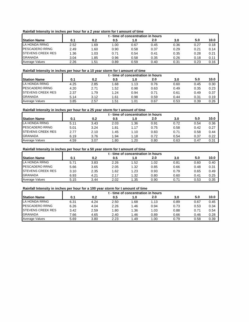
Rainfall Intensity in inches per hour for a 2 year storm for t amount of timet - time of concentration in hours
Station Name 0.1 0.2 0.5 1.0 2.0 3.0 5.0 10.0LA HONDA RRNG 2.52 1.69 1.00 0.67 0.45 0.36 0.27 0.18PESCADERO RRNG 2.49 1.60 0.90 0.58 0.37 0.29 0.21 0.14STEVENS CREEK RES 1.36 1.03 0.71 0.54 0.41 0.35 0.28 0.21GRANADA 3.04 1.85 0.96 0.58 0.35 0.26 0.18 0.11Average Values 2.26 1.51 0.89 0.59 0.40 0.31 0.23 0.16
Rainfall Intensity in inches per hour for a 10 year storm for t amount of timet - time of concentration in hours
Station Name 0.1 0.2 0.5 1.0 2.0 3.0 5.0 10.0LA HONDA RRNG 4.25 2.85 1.68 1.13 0.76 0.60 0.45 0.30PESCADERO RRNG 4.20 2.71 1.52 0.98 0.63 0.49 0.35 0.23STEVENS CREEK RES 2.37 1.79 1.24 0.94 0.71 0.61 0.49 0.37GRANADA 5.14 3.12 1.61 0.98 0.59 0.44 0.31 0.19Average Values 3.85 2.57 1.51 1.01 0.67 0.53 0.39 0.26
Rainfall Intensity in inches per hour for a 25 year storm for t amount of timet - time of concentration in hours
Station Name 0.1 0.2 0.5 1.0 2.0 3.0 5.0 10.0LA HONDA RRNG 5.11 3.43 2.03 1.36 0.91 0.72 0.54 0.36PESCADERO RRNG 5.01 3.24 1.81 1.17 0.75 0.58 0.42 0.27STEVENS CREEK RES 2.77 2.10 1.45 1.10 0.83 0.71 0.58 0.44GRANADA 6.19 3.76 1.94 1.18 0.72 0.54 0.37 0.22Average Values 4.59 3.07 1.80 1.20 0.80 0.63 0.47 0.31
Rainfall Intensity in inches per hour for a 50 year storm for t amount of timet - time of concentration in hours
Station Name 0.1 0.2 0.5 1.0 2.0 3.0 5.0 10.0LA HONDA RRNG 5.71 3.83 2.26 1.52 1.02 0.81 0.60 0.40PESCADERO RRNG 5.66 3.65 2.05 1.32 0.85 0.66 0.48 0.31STEVENS CREEK RES 3.10 2.35 1.62 1.23 0.93 0.79 0.65 0.49GRANADA 6.93 4.21 2.17 1.32 0.80 0.60 0.41 0.25Average Values 5.15 3.44 2.02 1.35 0.90 0.71 0.53 0.35
Rainfall Intensity in inches per hour for a 100 year storm for t amount of timet - time of concentration in hours
Station Name 0.1 0.2 0.5 1.0 2.0 3.0 5.0 10.0LA HONDA RRNG 6.31 4.24 2.50 1.68 1.13 0.89 0.67 0.45PESCADERO RRNG 6.26 4.04 2.26 1.46 0.94 0.73 0.53 0.34STEVENS CREEK RES 3.42 2.59 1.80 1.36 1.03 0.88 0.71 0.54GRANADA 7.66 4.65 2.40 1.46 0.89 0.66 0.46 0.28Average Values 5.69 3.80 2.23 1.49 1.00 0.79 0.58 0.39
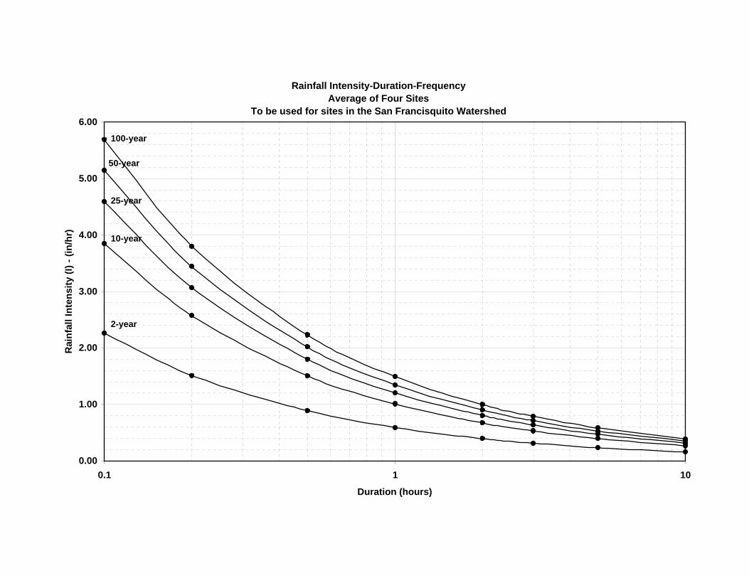
Rainfall Intensity-Duration-FrequencyAverage of Four Sites
To be used for sites in the San Francisquito Watershed
0.00
1.00
2.00
3.00
4.00
5.00
6.00
0.1 1 10
Duration (hours)
Rai
nfal
l Int
ensi
ty (I
) - (i
n/hr
)
2-year
10-year
25-year
50-year
100-year
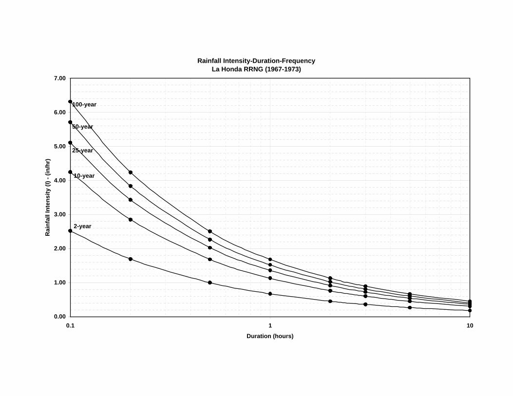
Rainfall Intensity-Duration-FrequencyLa Honda RRNG (1967-1973)
0.00
1.00
2.00
3.00
4.00
5.00
6.00
7.00
0.1 1 10
Duration (hours)
Rai
nfal
l Int
ensi
ty (I
) - (i
n/hr
)
2-year
10-year
25-year
50-year
100-year

Rainfall Intensity-Duration-Frequency CurvesPescadero RRNG (1967-1973)
0.00
1.00
2.00
3.00
4.00
5.00
6.00
7.00
0.1 1 10
Duration (hours)
Rai
nfal
l Int
ensi
ty (I
) - (i
n/hr
)
2-year
10-year
25-year
50-year
100-year
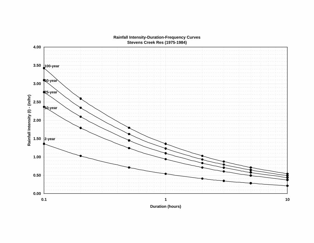
Rainfall Intensity-Duration-Frequency CurvesStevens Creek Res (1975-1984)
0.00
0.50
1.00
1.50
2.00
2.50
3.00
3.50
4.00
0.1 1 10
Duration (hours)
Rai
nfal
l Int
ensi
ty (I
) - (i
n/hr
)
2-year
10-year
25-year
50-year
100-year
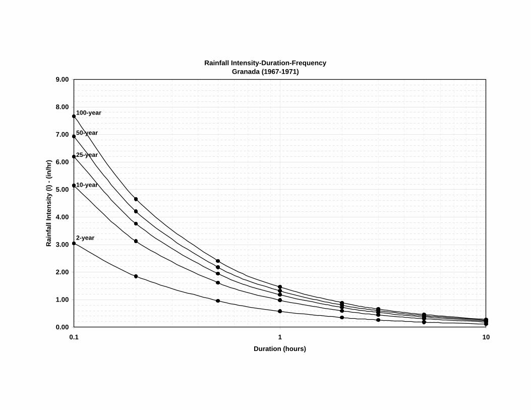
Rainfall Intensity-Duration-FrequencyGranada (1967-1971)
0.00
1.00
2.00
3.00
4.00
5.00
6.00
7.00
8.00
9.00
0.1 1 10
Duration (hours)
Rai
nfal
l Int
ensi
ty (I
) - (i
n/hr
)
2-year
10-year
25-year
50-year
100-year