Embed Size (px)
Citation preview

Durham E-Theses
An analysis of the dynamic performance of D.C.
machines with thyristor assisted commutation
Moore, J. R.
How to cite:
Moore, J. R. (1972) An analysis of the dynamic performance of D.C. machines with thyristor assisted
commutation, Durham theses, Durham University. Available at Durham E-Theses Online:http://etheses.dur.ac.uk/8620/
Use policy
The full-text may be used and/or reproduced, and given to third parties in any format or medium, without prior permission orcharge, for personal research or study, educational, or not-for-pro�t purposes provided that:
• a full bibliographic reference is made to the original source
• a link is made to the metadata record in Durham E-Theses
• the full-text is not changed in any way
The full-text must not be sold in any format or medium without the formal permission of the copyright holders.
Please consult the full Durham E-Theses policy for further details.

Academic Support O�ce, Durham University, University O�ce, Old Elvet, Durham DH1 3HPe-mail: [email protected] Tel: +44 0191 334 6107
http://etheses.dur.ac.uk
2

An A n a l y s i s of the Dynamic Performance
of
D.C. Machines
with t h y r i s t o r a s s i s t e d commutation
by
J.R. Moore, B.Sc.
T h e s i s submitted for the degree of Doctor
of Philosophy i n the F a c u l t y of Science
i n the U n i v e r s i t y of Durham
May 1972
1 3 JUN1972 ttWB
A b s t r a c t
The t h e s i s presents a method of a n a l y s i s of d i r e c t c u r r e n t
machines using t h y r i s t o r a s s i s t e d commutation. The method i s
based upon the General Machine Theory and the formulation of
voltage and torque equations from the theory i s shown to be
s u c c e s s f u l . These equations have p r e d i c t e d the performance of
the machine over a wide range of operating c o n d i t i o n s . A computer
programme has been developed to d e a l with the most complex
operating conditions and, by s u i t a b l e s i m p l i f i c a t i o n s , the programme
i s r e a d i l y adaptable to compute steady s t a t e c h a r a c t e r i s t i c s .
A subsidary theme of the t h e s i s i s to show how the output of
t h y r i s t o r a s s i s t e d machines may be c o n t r o l l e d by an e l e c t r o n i c
method of rocking the brushes. The method i s simply demonstrated
on no load or l i g h t load c o n d i t i o n s but l o a d i n g e f f e c t s produce
some l i m i t a t i o n s . S u f f i c i e n t experimental r e s u l t s are given to
i l l u s t r a t e the method.

Table of Contents
A b s t r a c t i
Table of Contents i i
L i s t of Symbols and Abbreviations v i
Chapter 1 I n t r o d u c t i o n 1
1.1 Object of T h e s i s 1
1.2 H i s t o r i c a l Background 2
1.3 Theory of Operation of T.A.C. Machines 3
1.4- I n t r o d u c t i o n to the T h e s i s 6
Chapter 2 D e r i v a t i o n of Machine Equations 9
2.1 The General Machine Theory 9
2.2 The Voltage Equation 9
2.3 The Nature of the Inductances 11
Z.h . The A c t i o n of the Commutator 12
2.5 The Commutator and S l i p Ring Voltage Equations 12
2.6 Average Values 15
2.7 Power and Torque Equations 16
Chapter 3 The S e l f and Mutual Inductance Parameters 18
3.1 Measurement of S e l f and Mutual Inductance 18
3.2 S e l f Inductances 18
3.3 Mutual Inductances 21
3.^ S a t u r a t i o n 25
3-5 D e r i v i t i v e or Slope? 25
Chapter k The A n a l y t i c a l S o l u t i o n 27
+.1 D i f f e r e n t i a l Equation for S e r i e s I n t e r p o l e 27
Machines
i i

if. 2 Forms of S o l u t i o n 30
A-.3 Comparison of A n a l y t i c a l S o l u t i o n with 33
Experimental Motor
k.k D i f f e r e n t i a l Equation for S e p a r a t e l y E x c i t e d 35
I n t e r p o l e s
Chapter 5 Comparison of Computed and Experimental 37
C h a r a c t e r i s t i c s
5.1 The Computer Programme 37
5.2 Steady State Comparisons 38
5.3 T r a n s i e n t Comparisons
5.^ D i s c u s s i o n on the Computer Model 4-8
5.5 Commutating A b i l i t y of Machine 51
Chapter 6 D i s c u s s i o n on the Speed O s c i l l a t i o n s 53
6.1 Comparisons with conventional machines 53
6.2 Methods of Prevention of Speed O s c i l l a t i o n s 5^
6.3 D i s c u s s i o n of the S t a b i l i t y C r i t e r i a 57
Chapter 7 Con t r o l of the T.A.C. Machine by Delayed 61
T h y r i s t o r F i r i n g
7.1 E f f e c t of Delayed T h y r i s t o r F i r i n g 61
7.2 P r a c t i c a l Method of Moving Axis 61
7.3 Motor C h a r a c t e r i s t i c s - L i g h t Loadings 63
7.4 E f f e c t s of Loading on Motor C o n t r o l 66
7.^.1 Commutation Angles 66
7.^.2 Speed - Torque C h a r a c t e r i s t i c s 66
7.5 Generator C h a r a c t e r i s t i c s 72
7«5-1 Generator Response 72
7.5.2 L i n e a r i t y of Generator C o n t r o l 75
i i i
7 - 5 « 3 G a i n and F r e q u e n c y Responses 75
7 . 6 D i s c u s s i o n on the C o n t r o l of D.C. machines 78
C h a p t e r 8 The E x p e r i m e n t a l Machine 81
8 . 1 D e t a i l s of the E x p e r i m e n t a l Machine 81
8 . 2 The P a r t Commutators 81
8 . 3 B r u s h P o s i t i o n s and Commutation A n g l e s 86
8 . ^ The T r i g g e r i n g C i r c u i t s 86
8 . 5 The E l e c t r o n i c and E l e c t r i c a l C i r c u i t s 89
C h a p t e r 9 C o n c l u s i o n s and Recommendations 9^
9 . 1 Comments and Recommendations 9 ^
9 . 2 C o n c l u s i o n 95
9 . 3 F u r t h e r Work 97
Appendix A The Measurement of I n d u c t a n c e 99
A . 1 The D.C. I n d u c t a n c e B r i d g e 99
A.2 C a l i b r a t i o n and Use of B r i d g e 101
A. 3 P r a c t i c a l D i f f i c u l t i e s w i t h the B r i d g e 102
Appendix B The Computer Programme 105
B. 1 F l o w c h a r t and Computer Programme 105
B. 2 I n t r o d u c t i o n of S t e p Changes 106
Appendix C E x p e r i m e n t a l D e t a i l s 111
C. 1 Machine D e t a i l s 111
C . 2 E l e c t r i c a l D e t a i l s 112
C . 3 Magnetic C i r c u i t D e t a . i l s 113
C.^ Del a y Times of C o n t r o l U n i t 1 1 ^
R e f e r e n c e s 115
Acknowledgements v i i i
i v

L i s t of Symbols and Abbreviations
(* denotes t h a t l e t t e r i s u s u a l l y a s u b s c r i p t )
Roman Alphabet
a * main armature c o i l during commutation
A * armature c o i l during s l i p r i n g period
A u n i t of c u r r e n t , ampere
AT ampere turn
b brush a r c
B f l u x d e n s i t y , T e s l a
c * shorted armature c o i l during commutation
d d i r e c t a x i s of machine
e base of n a t u r a l logarithms
f • f i e l d winding
H u n i t of inductance, henry
i * i n t e r p o l e winding
i a * s e r i e s connection of i n t e r p o l e and main armature windings
iA * s e r i e s connection of i n t e r p o l e and armature windings
I c u r r e n t
J i n e r t i a
K constant
1 length
L s e l f inductance
M mutual inductance
m u n i t of length, metre
N u n i t of f o r c e , newton
p d i f f e r e n t i a l operator (d/dt)
P power
q quadrature a x i s of machine
r r a d i a n
R r e s i s t a n c e
v i

s segment arc
S u n i t of time, second
t time
T torque
v v e l o c i t y
V u n i t of voltage, v o l t
V voltage
x r a t i o
c o e f f i c e n t i n d i f f e r e n t i a l equation
damping f a c t o r
commutation angle
angle between armature and n e u t r a l axes
angle a t which commutation s t a r t s
voltage i n t e g r a l
r o t a t i o n a l speed, r a d i a n s per second
A b b r e v i a t i o n s a.c. a l t e r n a t i n g c u r r e n t
d.a.c. diode a s s i s t e d commutation
d. c. d i r e c t c u r r e n t
e. b.s. e l e c t r o n i c brush s h i f t
f . s.d. f u l l s c a l e d e f l e c t i o n
p.u. per u n i t
t . a . c . t h y r i s t o r a s s i s t e d commutation
Other symbols and a b b r e v i a t i o n s as defined i n the t e x t .
Greek Alphabet
f}> beta
£ gamma
£ d e l t a
Q t h e t a
phi
jjj p s i
omega
v i i

Chapter 1 I n t r o d u c t i o n
1.1 Object of T h e s i s
The general object of the work was to consider methods of
a n a l y s i n g the performance of d i r e c t current machines with t h y r i s t o r
a s s i s t e d commutation ( t . a . c . machines). E v e n t u a l l y , the method of
a n a l y s i s should enable the c h a r a c t e r i s t i c s of a machine at the
design stage to be c a l c u l a t e d and c o r r e c t i o n s made to obtain the
best performance. For standard d.c. machines many years of experience
have produced w e l l defined procedures which are based upon e s s e n t i a l l y
steady s t a t e methods. For conventional machines t h i s i s v a l i d
because the mmfs and f l u x e s are r e l a t i v e l y f i x e d . T.A.C. machines
have a wide commutating zone and the mmfs and f l u x e s are v a r i a b l e
over a wide range. Consequently, a dynamic type of a n a l y s i s was
thought to be more a p p l i c a b l e to the t . a . c . machine and a method
based upon the general machine theory was used. Such a method depends
upon the knowledge of inductance parameters and there are considerable
problems i n c a l c u l a t i n g them.
To t e s t the v a l i d i t y of the method of a n a l y s i s , the inductances
were measured on an experimental machine. I f the measured values
gave accurate p r e d i c t i o n s of the performance of the machine when
used with the general theory, then a f u r t h e r stage i n the a n a l y s i s
i s to consider how they may be c a l c u l a t e d from design c r i t e r i a . U n t i l
the v a l i d i t y of the method has been t e s t e d , there i s l i t t l e point i n
attempting the c a l c u l a t i o n s . During the work, the a n a l y s i s and
experimental work showed that the speed of the motor could o s c i l l a t e
under c e r t a i n operating c o n d i t i o n s . Although i t i s more important
to be able to c a l c u l a t e the standard c h a r a c t e r i s t i c s such as speed
torque, the p r e d i c t i o n of such phenomena provided a very good t e s t .
1 3 JUNI972 orion
1
The main theme of the t h e s i s i s to present a method of a n a l y s i s
of the experimental machine based upon the general machine theory.
The formulation of equations from the general theory has been
s u c c e s s f u l and these equations have p r e d i c t e d the the performance of
the machine over a wide range of operating c o n d i t i o n s . A computer
programme has been developed to d e a l with the most complex operating
c o n d i t i o n s and by s u i t a b l e s i m p l i f i c a t i o n s , the programme i s r e a d i l y
adaptable to compute the steady s t a t e c h a r a c t e r i s t i c s .
A subsidary theme i s to show how the output of t . a . c . machines
may be c o n t r o l l e d by an e l e c t r o n i c method of rocking the brushes.
The method i s simply demonstrated under l i g h t or no load conditions
but loading e f f e c t s produce some l i m i t a t i o n s . The concept i s
i n t e r e s t i n g and some experimental r e s u l t s are given but the method
has by no means been i n v e s t i g a t e d f u l l y .
1.2 H i s t o r i c a l Background
E a r l y a n a l y s e s and p r a c t i c a l experience had shown that
commutation problems were r e s p o n s i b l e for many of the d i f f i c u l t i e s
found i n d.c. machines. Improvements i n the form of i n t e r p o l e s and
compensating windings had helped but s i g n i f i c a n t improvements could
only be achieved by a removal or m o d i f i c a t i o n of the commutator and
commutation process.
With the i n t r o d u c t i o n of semiconductors many papers were
published on the c o n t r o l of d.c. machines by using these d e v i c e s .
I n general, these methods incorporated some form of armature voltage
c o n t r o l ; they did not remove or modify the commutator. Ideas of
u s i n g t h y r i s t o r s and diodes to a s s i s t the commutation process were (1 .1 1
published ' and i t was thought that the switched winding or
armature would be b e t t e r placed on the s t a t o r with the f i e l d winding

on the r o t o r . I n 196^, a p r a c t i c a l design for a d.c. motor with (1 2)
a s s i s t e d commutation was described by Bates, S r i d h a r and T u s t i n
and the r e s u l t s of t e s t s on a small machine were given a year or so
l a t e r ' . Bates et a l . showed tha t once the commutation process
was no longer dependent upon the carbon brush for the s u c c e s s f u l
r e v e r s a l of current i n the armature, i t was p o s s i b l e to get a much
improved performance from the machine. This a d d i t i o n a l performance
for a given frame s i z e w e l l j u s t i f i e d the cost of the e x t r a equipment.
Recent machines have been b u i l t up to power l e v e l s of kOO hp . Other schemes a l s o e x i s t for a s s i s t i n g the commutation p r o c e s s .
(1.5)
Andrews " suggested the use of a laminated brush c o n s i s t i n g of
four or more s l i c e s i n s u l a t e d from each other. A t h y r i s t o r was
connected to each s l i c e and, by s u i t a b l e arrangements, the c u r r e n t
can be t r a n s f e r r e d from s l i c e to s l i c e without the s l i c e a c t u a l l y
making or breaking contact with a commutator bar while i t i s s t i l l
c a r r y i n g c u r r e n t . Other methods u s u a l l y involve turning the machine
i n s i d e out, p u t t i n g the f i e l d system on the r o t o r and the armature
winding around the s t a t o r
Each method o f f e r s advantages over the conventional machine.
I n g e n e r a l , these new methods remove some of the more r e s t r i c t i v e
commutation problems and allow more power to be obtained from a
given frame s i z e . The disadvantages are u s u a l l y those of a d d i t i o n a l
equipment with t h e i r e x t r a c o s t .
1.3 Theory of Operation of T.A.C. Machines
The t . a . c . machine uses a conventional armature winding but
i n s t e a d of a s i n g l e commutator, there are two part commutators. Each
part commutator has only eight or so segments and the tappings from
the armature winding are connected to a l t e r n a t e segments. Four

brushes feed c u r r e n t i n t o the armature and are arranged i n two p a i r s .
Each p a i r i s connected i n p a r a l l e l and to the t h y r i s t o r . The t h y r i s t o r
i s t r i g g e r e d by a contact operated from a s y n c h r o n i s i n g r i n g on the
s h a f t . Figure 1.1 shows the schematic arrangement.
Commutation of the c u r r e n t i n the armature winding takes place
as f o l l o w s . Assume i n i t i a l l y that t h y r i s t o r T 2 i s conducting and
that the curr e n t i s flowing i n t o the armature v i a brush b22 and
segment S21 as shown i n Figure 1.1. When brush b11 i s j u s t f u l l y on
S12, T1 i s f i r e d i n t o conduction. Commutation now proceeds under
the a c t i o n of the i n t e r p o l e induced voltage i n the c l o s e d c i r c u i t
formed by T1 , b11., S12, the c o i l C 1 2 , S21 , b22 and T 2 . The p o l a r i t y
of the voltage i s such that the curr e n t through T 2 tends to reduce;
that through T1 to i n c r e a s e . As long as the current through T 2 i s
reduced to zero before b22 l e a v e s S21, the brush w i l l leave the
segment c a r r y i n g no curr e n t and there must be no sparking. A l l the
c u r r e n t now e n t e r s through T 1 . As the brushes move, b12 w i l l take
over the current from b11 and e v e n t u a l l y , b21 w i l l j u s t be on S23-
The commutation process r e p e a t s as T 2 i s f i r e d . This time T1 goes
'off* while T 2 comes 'on*. The process repeats each time the l e a d i n g
brushes are j u s t completely on the beginning of an a c t i v e segment.
Three p o i n t s are worthy of note. F i r s t l y , as long as the c u r r e n t
through a t r a i l i n g brush i s brought to zero before the brush l e a v e s
the segment, no sparking w i l l occur. T h i s i m p l i e s that there i s a
minimum value for the i n t e r p o l a r induced f l u x but no maximum. There
appears to be no reason why the i n t e r p o l e cannot be made much stronger
than necessary so that commutation w i l l be complete w e l l before the
brush reaches the end of the segment. While t h i s would give the
machine a degree of p r o t e c t i o n a g a i n s t shock loadings, i t i s p o s s i b l e
for the t . a . c . motor speed to o s c i l l a t e continuously when u s i n g an

i n t e r p o l e induced voltage
J-C12 C23
S21 S22 S23
b22 b21
S11 S12 _si3
b12 b11
A K T2 T1
+V
F i g . 1.1 Schematic Diagram of T h y r i s t o r a s s i s t e d
Commutation
5

overwound, s e r i e s connected i n t e r p o l e winding. T h i s o s c i l l a t o r y
nature i s shown and d i s c u s s e d i n l a t e r chapters.
The second point i s that at no time does the brush bring about
commutation. They act only as a s l i d i n g contact between the armature
winding and the e x t e r n a l c i r c u i t . The s w i t c h i n g of c u r r e n t s i s done
e n t i r e l y by the t h y r i s t o r s . The f i r i n g of a t h y r i s t o r i s always
c a r r i e d out when the brush i s s i t t i n g completely on a segment -
never when i t i s bridging two segments. T h i s e l i m i n a t e s the p o s s i b i l
of u n c e r t a i n contact between the brush and segment.
The t h i r d point follows from the second. As commutation i s
not s t a r t e d u n t i l a brush i s completely on a segment and must be
f i n i s h e d before the brush on the other p a r t commutator lea v e s the
segment, commutation takes place i n d i s c r e t e i n t e r v a l s and not
continuously as i n conventional d.c. machines. The i n t e r v a l i s
determined by the brush and segment geometry and by the strength of
the i n t e r p o l e f l u x . Between these i n t e r v a l s there i s no commutation
and the machine a c t s as a s l i p r i n g machine. T.A.C. machines, t h e r e
fo r e , operate with two zones. A commutation zone i s followed by the
s l i p r i n g zone and the r e l a t i v e times of each zone obviously depend
upon .the time of commutation.
1.*f I n t r o d u c t i o n to the T h e s i s
The use of conventional machine a n a l y s i s allows the steady
s t a t e c h a r a c t e r i s t i c s of a machine to be e a s i l y c a l c u l a t e d but does
not g e n e r a l l y permit d e t a i l e d information to be obtained under
changing or t r a n s i e n t c o n d i t i o n s . For standard machines, the mmfs
and f l u x e s are r e l a t i v e l y f i x e d owing to the small commutating zone
of about i2°. The commutation zone i n t . a . c . machines i s not s m a l l
( i . e . 32° i n the experimental machine) and the commutation process

i s not continuous. At the end of each zone there i s a la r g e change
i n the armature a x i s p o s i t i o n and so the mmfs and f l u x e s are c o n t i n u a l l y
moving. The method of a n a l y s i s was based upon a general type i n
which the dynamics are included from the s t a r t , Such a method i s
the general machine theory and the s t a r t i n g point f or the a n a l y s i s
i s the voltage and torque equations f o r four mutually coupled c o i l s .
I n chapter 2, these r e l a t i o n s h i p s are formulated i n t o dynamic equations
which take account of the d i f f e r e n c e s between conventional and t . a . c .
machines. These d i f f e r e n c e s i n c l u d e the two zones of operation, the
la r g e angles over which the armature a x i s can move and the presence
of t h y r i s t o r s i n the armature c i r c u i t .
The method of a n a l y s i s r e q u i r e s the v a r i a t i o n of the inductances
with r o t o r angle to be known and while these v a r i a t i o n s are easy to
measure i t would be d i f f i c u l t to c a l c u l a t e them. I f , however, by
using the measured v a l u e s , the c h a r a c t e r i s t i c s can be a c c u r a t e l y
p r e d i c t e d then the v a l i d i t y of the method w i l l be confirmed. The
next stage i n the a n a l y s i s would be to consider methods of c a l c u l a t i n g
the inductances from the p h y s i c a l and e l e c t r i c a l parameters of the
machine. I t i s f i r s t necessary to prove the method and the inductances
were measured on a small experimental machine. The r e s u l t s are given
i n chapter 3 and the method of measurement i n Appendix A.
Using the equations and the v a r i a t i o n of inductance, the a n a l y s i s
i s continued i n two ways. F i r s t , a formal method using d i f f e r e n t i a l
equations i s used to show the form of behaviour under various
operating c o n d i t i o n s and t h i s method i s shown i n chapter k. The
second method uses the equations as the foundation for a computer
programme to a c c u r a t e l y p r e d i c t the performance of the machine. The
computer programme and d e t a i l e d comparisons between the p r e d i c t e d and
a c t u a l behaviour of the t . a . c . machine are given i n chapter 5 . The
7

computer programme i s f u l l y d e s c r i b e d i n Appendix B. I n both the
formal and computer analyse s and a l s o i n the experimental machine,
the steady s t a t e c h a r a c t e r i s t i c s of the s e r i e s connected i n t e r p o l e
motor would degenerate i n t o a continuous speed and c u r r e n t o s c i l l a t i o n
under c e r t a i n f i e l d current and load torque c o n d i t i o n s . Although
such o s c i l l a t i o n s are of l i t t l e p r a c t i c a l use, t h e i r accurate
p r e d i c t i o n enables the a n a l y s i s to be used with greater confidence.
The o s c i l l a t i o n s and methods of prevention are d i s c u s s e d i n chapter 6.
Since commutation i s no longer performed by the brushes but
r a t h e r c o n t r o l l e d by the t h y r i s t o r s , the commutation zone i s not
l i m i t e d to a s m a l l zone about the i n t e r p o l a r a x i s . By using a. s m a l l
commutating zone, the average p o s i t i o n of the armature a x i s may be
a d j u s t e d and an e f f e c t obtained which i s s i m i l a r to rocking the brushes
i n a conventional d.c. machine. To move the armature a x i s , a c o n t r o l
u n i t was c o n s t r u c t e d which e l e c t r o n i c a l l y rocked the brushes by
d e l a y i n g the t h y r i s t o r f i r i n g p u l s e s . The concept i s explained i n
chapter 7 and the method amply i l l u s t r a t e d by the machine's performance
on l i g h t and no l o a d s . Loading e f f e c t s c r e a t e some f u r t h e r l i m i t a t i o n s
and widespread a p p l i c a t i o n of the method may not be p o s s i b l e . The
r e s u l t s show the scope of the method but i t has by no means been f u l l y
i n v e s t i g a t e d .
P r a c t i c a l d e t a i l s of the machine and the e l e c t r i c a l and e l e c t r o n i c
c i r c u i t s are to be found i n chapter 8 with f u r t h e r d e t a i l on c e r t a i n
p o i n t s given i n Appendix C. Futuro work u s i n g tho oxporimontal
machine—to i n v e s t i g a t o — f l u x p u l c a t i o n e i c i n d i G a t o d i n chapter 9
The t h e s i s i s concluded by the comments and recommendations which are
given, along with the general c o n c l u s i o n , i n chapter
8
Chapter 2 D e r i v a t i o n of Machine Equations
2.1 The General Machine Theory
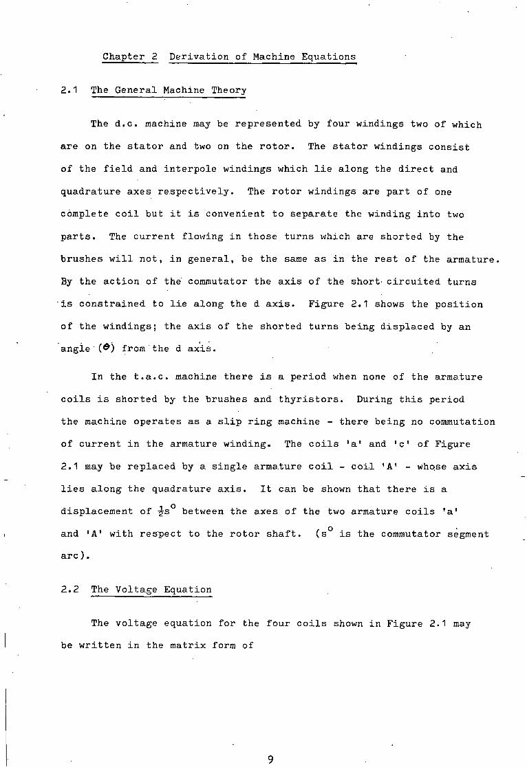
The d.c. machine may be represented by four windings two of which
are on the s t a t o r and two on the r o t o r . The s t a t o r windings c o n s i s t
of the f i e l d and i n t e r p o l e windings which l i e along the d i r e c t and
quadrature axes r e s p e c t i v e l y . The r o t o r windings are part of one
complete c o i l but i t i s convenient to separate the winding i n t o two
p a r t s . The c u r r e n t flowing i n those turns which are shorted by the
brushes w i l l not, i n general, be the same as i n the r e s t of the armature.
By the a c t i o n of the commutator the a x i s of the short' c i r c u i t e d turns
i s c o n s t r a i n e d to l i e along the d a x i s . Figure 2.1 shows the p o s i t i o n
of the windings; the a x i s of the shorted t u r n s being d i s p l a c e d by an
angie'(£) from the d a x i s .
I n the t . a . c . machine there i s a period when none of the armature
c o i l s i s shorted by the brushes and t h y r i s t o r s . During t h i s period
the machine operates as a s l i p r i n g machine - there being no commutation
of c u r r e n t i n the armature winding. The c o i l s 'a' and 'c' of Figure
2.1 may be r e p l a c e d by a. s i n g l e armature c o i l - c o i l 'A' - whose a x i s
l i e s along the quadrature a x i s . I t can be shown that there i s a
displacement of -g-s between the axes of the two armature c o i l s 'a'
and 'A' with r e s p e c t to the r o t o r s h a f t . (s° i s the commutator segment
a r c ) .
2.2 The Voltage Equation
The voltage equation for the four c o i l s shown i n F i g u r e 2.1 may
be w r i t t e n i n the matrix form of
9

d axis
F i e l d
Interpole a axis
F i g . 2.1 Four Winding representation of a D.C. Machine
10

X
\ p > v I .
where p i s the d i f f e r e n t i a l operator d/dt.
The general term p M ^ . I ^ may be expanded to obtain
pM .1 = M . p i xy y xy * y
+ I .pM y xy
which may be r e w r i t t e n as
pM .1 '= M . p i xy y xy y + I ,(P.d(M )/dd y xy
where CO i s the r o t a t i o n a l speed i n radians per second.
To solve the above m a t r i x equation, the value of d(M )/&& i s xy
r e q u i r e d . That i s , the v a r i a t i o n of M w i t h the angle 0 must be xy
obtained.
2...3 The. Nature of the Inductances
The s e l f inductance of each winding and the mutual inductance
between p a i r s of windings were measured and the r e s u l t s are given
i n d e t a i l i n Chapter 3- I n t h i s s e c t i o n , only the form of the
inductances are i n d i c a t e d so th a t the d e r i v a t i o n of the machine
equations may be continued f o r the t.a..c. machine.
The s t a t o r s e l f inductances were independent of r o t o r angle but
dependent upon the c o i l c u r r e n t . A l l the inductances were a f f e c t e d
by s a t u r a t i o n and care must be taken to ensure t h a t s a t u r a t i o n e f f e c t s

are included i n the a n a l y s i s . The r o t o r s e l f inductances were
dependent upon r o t o r angle at low cu r r e n t s but a t rate d f i e l d and
i n t e r p o l e current the e f f e c t s of r o t o r angle were neg l i g a b l e . The
mutual inductances were very dependent upon r o t o r angle, the v a r i a t i o n
of inductance being of a sine or cosine f u n c t i o n . Table 2.1 gives
the form of the inductance waveforms, t h e i r values and d e r i v i t i v e s
around the commutating zone.
2.k The A c t i o n of the Commutator
I n a conventional machine the commutator l i m i t s the v a r i a t i o n
of 6 t o a small range about the p o s i t i o n 6 = 0°. S i s the angle
of commutation and has a t y p i c a l value of 5°. With t h i s small angle
(i2-J^) any cosine f u n c t i o n may be assumed to remain at i t s maximum
value throughout commutation and, a l s o , the mean value of any sine
f u n c t i o n t o be zero. This assumption i s not v a l i d i n the t.a.c.
machine since the commutation angle i s not small and, except i n the
sp e c i a l case of commutation t a k i n g a l l the a v a i l a b l e angle, the
average armature a x i s p o s i t i o n w i l l not l i e along the quadrature a x i s
(©=0°).
To s i m p l i f y the i n i t i a l a n a l y s i s the assumption t h a t any cosine
type of f u n c t i o n w i l l remain at i t s maximum value i s used. This
introduces a maximum e r r o r of k% when commutation occurs very r a p i d l y
but under more normal c o n d i t i o n s , the e r r o r i s t y p i c a l l y 1.5%« Sine
f u n c t i o n s are included as such and are not approximated t o zero.
2.5 The Commutator and S l i p Ring Voltage Equations
The voltage equation of sec t i o n 2.2 may be expanded to give the
commutator and s l i p r i n g voltage equations f o r the t.a.c. machine.
For the commutation period, the voltage equation i s
12

Inductance Type of Value around Value of derivative Waveform 8 = 0° around 9 = 0°
Self
J f f
A
L
0
0
0
0
0
Mutual
M f . i M f.a
"f.A M f.c M. l . a i.A M. i. c M a.c
sine
sine
cosine
cosine
cosine
sine
sine
M f^ a.sin(e)
M f > A.sin(e)
M A M. f.c
l . a M. A l.A
M. .sin(0) 1 • c M .sin(2e)
f.a
f.A -M f > c.sin(0)
-M. .sin(-0)
-M i > A.sin(0) • A M. l.c 2M a.c
Table 2.1 Values of Inductances and Derivatives
13

h T V f — - M , • u,
V i — A
A « • P * v .
A Sin © • p
A
A c . r
A Mac • J I M 2 0 ^
— M/ . sm © • u> **•
A
M,c-i'«20- p A
Re * U- p
where M represents the maximum value of the inductance M xy xy.
I n t.a.c. machines, as i n conventional d.c. machines, the i n t e r p o l e
winding may be connected i n series o p p o s i t i o n to the armature winding
and the voltage equation may be r e w r i t t e n as A *
—
- M | c S m 0 p A
- Pi i f <-» X
~ M ^ . j i v i © . o> A A
X c
where V. l a
i s the voltage across the se r i e s connected i n t e r p o l e and
armature windings and 1^ i s the current through them.
During the s l i p r i n g period the short c i r c u i t e d c o i l s become
e l e c t r i c a l l y p a r t of the armature winding and the s l i p r i n g voltage
equation, f o r s e r i e s connected i n t e r p o l e s , i s
14

A A
X
*A * U r
2 M(.A-Cir|&-LO
For s e r i e s connected i n t e r p o l e s , the r e s i s t ance and inductance
of the armature and i n t e r p o l e windings may be denoted by R. and L l a i a
i n the commutator equations and by R^ and i n the s l i p r i n g
equations. Therefore
and
R. = R. + R l a i a
L. = L. + L l a i a - 2M.
and s i m i l a r l y f o r R.. and L... J xA xA
found to be zero,
xa Since d ( L . ) / d t and' d(L )/dt were
1 3.
pL. . I . = L . . p i . xa l a x xa
+ L . p i . a xa
- 2M. . p i . + 2M. . w . s i n ( e ) . l . xa r xa xa xa
which i s consistent w i t h the voltage equations above.
2.6 Average Values
The voltages and currents i n the machine obviously depend upon
both the commutator and s l i p r i n g equations. The o v e r a l l equation
r e l a t i n g voltage and current i s therefore lengthy and r a t h e r cumbersome.
The above equations are c o r r e c t f o r e i t h e r instantaneous or average
values of 6 but i f only the average values are required some
s i m p l i f i c a t i o n of the equations may be made. For example, the average
value of the cu r r e n t i n the short c i r c u i t e d armature winding i s zero
and so any term c o n t a i n i n g I w i l l also be zero and may be deleted
from the equations,

For average values only the following, assumption was made.
The mean value of a machine parameter i s the sum of x times i t s
commutator value and (1-x) times i t s s l i p r i n g value. x i s defined
as the r a t i o of the commutation time t o the sum of the commutation
and s l i p r i n g times.
2.7 Power and Torque Equations
The power in p u t t o a c i r c u i t c o n t a i n i n g resistance and s e l f and
mutual inductance i s
2 v . i = i . r + i . p ( L . i ) + i . p ( M . i ^ )
which may be expanded t o give
2 2 v . i = x . r + i .pL + L.x.pi + i.i^.pM + i.M.pi^
However, 2 2 d(-g-L.i ) / dt = -g-i .pL + L . i . p i
so 2 2 2
v . i = i .r + p ( - j L . i ) + -g-i .pL + i.i^.pM + i.M.pi^
I f there i s no r o t a r y motion then pL = pM = 0 and a l l the power
supplied t o the c i r c u i t i s e i t h e r d i s s i p a t e d as heat or used to
increase the energy stored i n the s e l f and mutual f i e l d s . I f r o t a r y
motion does occur, then the powers associated w i t h the terms pL
and pM must provide the power f o r tha.t motion. The power converted
to mechanical power must t h e r e f o r e be
" *•«••«•» /dQ L-L,- CO- / i &
From the previous voltage equations the power converted during
+ n i ( i . jm © • u> • i f , + 2 ti^.u,.!,. T i a
the commutation period i s •torn*, - ~ f |<»- «*> If-Tip
- Pile -uj.lV
16

and t h i s may be s i m p l i f i e d to
i f only the average power converted i s required since, as pr e v i o u s l y
s t a t e d , the mean value of I i s zero. The power converted during the
s l i p r i n g p e r i o d i s given by
The t o t a l average power converted from e l e c t r i c a l t o mechanical power
or vice versa i s
P = x.P + ( 1 - x ) . P _. comm s l i p
The converted power provides a. torque which overcomes f r i c t i o n
and d r i v e s the load - any excess accelerates the system. The t o t a l
mechanical power requirement i s
Power = Torque . speed
P = (T + J.d"/dt) . <o
The t o t a l e l e c t r i c a l and mechanical powers may be equated to ob t a i n
x.P + (1-x).P . . = (T + J.d»/dt).oJ
comm s l i p
This i s an expression which l i n k s the e l e c t r i c a l and mechanical
parameters of the machine and together w i t h the voltage equations may
be used to analyse the performance of the t.a.c. machine.

Chapter 3 The S e l f and Mutual Inductance Parameters
3.1 Measurement of S e l f and Mutual Inductance
During the d e r i v a t i o n of the voltage equations the v a r i a t i o n s of
the inductance parameters w i t h r o t o r angle were r e q u i r e d . The form
of the v a r i a t i o n s , i . e . sine or cosine f u n c t i o n s , were given i n Table
2.1 and i n t h i s chapter the d e t a i l e d waveforms are shown and discussed.
The inductances were measured using the d i r e c t current inductance (3.1)
bridge developed independently by Jones ' and Prescott and (3.2)
El-Karashi * . D e t a i l s of the theory, the operation and p r a c t i c a l
d i f f i c u l t i e s i n using the bridge are given i n Appendix A. The
measurement of the inducta.nces was done using currents i n the range.
0.05 to 2.0 of the r a t e d value f o r t h a t c o i l . I n i t i a l l y , much smaller
currents ( t y p i c a l l y 0.001 A.) were used but these produced misleading
r e s u l t s due to leakage e f f e c t s . The e f f e c t s of h y s t e r i s were
minimised by-taking the average of two readings using equal current
flow i n opposite d i r e c t i o n s . 3.2 S e l f Inductances
The s e l f inductances of the f i e l d and i n t e r p o l e windings were
independent of r o t o r p o s i t i o n but dependent upon the value of the
current f l o w i n g i n the c o i l . There was l i t t l e cross s a t u r a t i o n : a
change i n the f i e l d c u r r e n t from zero to rated value produced a 1*f%
r e d u c t i o n i n the f i e l d s e l f inductance but only a. JP/o change i n the
i n t e r p o l e s e l f inductance. The v a r i a t i o n of the s e l f inductances of
the f i e l d and i n t e r p o l e windings are shown i n Figure 3>1 (a) and (b)
r e s p e c t i v e l y .
The r o t o r s e l f inductances were dependent upon both r o t o r p o s i t i o n
and the f i e l d and i n t e r p o l e c u r r e n t s - i . e . upon the d and q axes
18

S e l f Inductance - - Henry 600-
500-
*K>0-
300-
200-
100-
- I * =
50mA
150mA 10mA
90 — I — 180
- l — 270
— I — 360
Rotor Position
(a) F i e l d S e l f Inductance - L f
Self Inductance - - Henry 0.35 J 0.30 -
0.25 "
0.20 -
0.15 -
0.10 -
0.05 "
0.0
- I i = 50mA
I 90
- I 1 1 180 270 360
Rotor Position
(b) Interpole S e l f Inductance - L. 1
Fig. 3.1 (a,b) Variation of Se l f Inductance
19

(c) Main Armature S e l f Inductance - L a , L A
S e l f Inductance - Henry
0.12-
0.10-
0.08-
0.06-
0.04-
0.02-
i 0* 90
Conditions - ( i ) 1 , =
( i i ) I , =
180* 270" 360 Rotor Position
0.0A I . = OA 1 0.3A I ± = 10A
( i )
( i i )
S e l f Inductance - Henry 0.016
0.014-
0.012
0.010-
0 .008-
0.006-
0.004-
0.002-
0.0 90"
T T 180* 270" 360"
Rotor Position
(d) Armature Shorted Turns Self Inductance - L,
( i )
( i i )
Fig. 3.1 (c,d) Variation of S e l f Inductance
20

saturation l e v e l s . At and around the rated values of these currents
the effect of rotor angle was negligable, The variation of the s e l f
inductances of the main armature (L ).and the t o t a l armature ( L A ) a A
windings are shown in Figure 3«1 (c ) while that of the short c i r c u i t turns (L ) i s shown i n Figure 3»1 (d). c
3.3 Mutual Inductances
The mutual inductance between the f i e l d c o i l and the main armatur
windings (M^a and M^) changed appreciably with rotor angle - the
variation being of a modified sine wave - Figure 3*2 ( a ) . The
variation of the mutual inductance between the f i e l d and the armature
shorted turns (M_ ) was that of a. cosine function - Figure 3-2 (b).
The variation of the interpole - armature inductances followed a
cosine wave - Figure 3*2 (c) whilst that of the interpole - shorted
turns was a very modified type of sine wave - Figure 3-2 (d ) .
The variation of the main armature - shorted turns mutual
inductance (M ) with rotor angle was a sine wave of double the ac frequency of the other mutual inductances. The magnitude of M
was very dependent upon the d and q axes saturation l e v e l s and at
rated currents i n the stator c o i l s , the magnitude of M was almost e ac
negligable - Figure 3-2 ( e ) .
Lastly, the variation of the mutual inductance between the
f i e l d and the interpole c o i l s at different rotor angles was measured,
Figure 3*2 ( f ) . Since the two windings are in space quadrature there
should be no mutual inductance between them. A slight variation was
recorded and t h i s may be attributed to positioning errors of the rotor
interpole or the main f i e l d poles.

Mutual Inductance 6.0"
k . 0 -
2.0
0.0
- Henry
-2.0 H
-6.0 A
50mA
200mA
/ 270 360
Rotor Position
(a) F i e l d - Armature Mutual Inductance - , M, . f. a * r. A
Mutual Inductance - Henry
3.0-1
1.0 -
I f = 50mA
I f = 200mA
270 360 Rotor Position
-3.0 H
(b) F i e l d - Shorted Turns Mutual Inductance - M f^c
Fig* 3.2 (a,b) Variation of Mutual Inductance
22

Mutual Inductance - Henry 0.15-
0.10 2A M M \
0.05 10A M
180 360 90 / Rotor Position
0.05 \ / \
0.10
0.15
( c ) Interpole Armature Mutual Inductance M M
Mutual Inductance Henry 0.03 2A /
10A 0.02
0.01
i Rotor Position i
180 270 90
0.01 M
i 0.02
/
0.03
(d) Interpole Shorted Turns Mutual Inductance M
F i g . 3.2 (c,d) Variation of Mutual Inductance
23

Mutual Inductance - Henry 0.006 -
0.004 -
0.002-
0.0
-0.002
-0.004 -
-0.006 -
I f = OA , I ± = OA
f = O.JA , I i = 10A
Rotor Position
(e) Armature - Shorted Turns Mutual Inductance - M a.c
Mutual Inductance - Henry
0.03 "
0.02 -
0.01 -
0.0
I f = 50mA
/= 1* = 200mA
l 90
~ l 1 1 180 270 360
Rotor Position -0.01 -
-0.02 -
-0.03 "
( f ) F i e l d - Interpole Mutual Inductance - M„ i .x
F i g . 3.2 ( e , f ) Variation of Mutual Inductance
2k

3.4 S a t u r a t i o n
Throughout the above f i g u r e s the e f f e c t of s a t u r a t i o n may be
observed i n changing the values of the mutual inductances. For two
of these inductances, the' maximum value of t h a t inductance was
measured over a range of e x c i t i n g c u r r e n t s . Figure 3*3 (a) shows
the change of M„ w i t h f i e l d c u rrent I . . The value increased t o a f a i maximum at around 0.05 A. and then began to f a l l owing t o s a t u r a t i o n
i n the d i r e c t axis.. A s i m i l a r s i t u a t i o n e x i s t e d i n the q axis and
Figure 3-3 (b) gives the change of M^a w i t h i n t e r p o l e current I _ ^ .
The e f f e c t of s a t u r a t i o n i s very evident, the maximum value of M. l a
being almost halved as the i n t e r p o l e c u r r e n t was increased from 2
t o 10 amperes.
3«5 D e r i v a t i v e or Slope?
I n the voltage equations, i t i s the d e r i v a t i v e d(M ) / d© xy
which i s r e q u i r e d around the p o s i t i o n ©=0°. However, i t has been
found by t r i a l t h a t the value of the slope AM A © around the xy
p o s i t i o n Q=0° gave b e t t e r r e s u l t s than d i d the d i f f e r e n t i a l values.
This i s to be expected as the v a r i a t i o n s of inductance w i t h angle
were not pure sine or cosine f u n c t i o n s but contained higher harmonics.
As an example, the d i f f e r e n t i a l value of M^& was 12% higher than t h a t
c a l c u l a t e d from the slope /A9 . This l a t t e r value d i f f e r e d by
less than 3% from t h a t obtained experimentally from the open c i r c u i t
c h a r a c t e r i s t i c of the t.a.c. generator.
25

Mutual Inductance M f.a Henry/radian
6.0-
5.0-
4.0-
3.0-
X i 1 1 1 1— 50 100 150 200 250
. . F i e l d Current - mi l l i a m p e r e s
F i g . 3.3 a D i r e c t Axis S a t u r a t i o n
0.12"
0.10"
0.08-
0.06-
0.04-
Mutual Inductance M i . a Henry/radian
i T T T T 0 2 4 6 8 10 12
I n t e r p o l e Current
F i g . 3.3 b Quadrature Axis S a t u r a t i o n
26
1 14
- amperes

Chapter k The A n a l y t i c a l S o l u t i o n
D i f f e r e n t i a l Equation for S e r i e s I n t e r p o l e Machines
An accurate formal s o l u t i o n of the equations of the t . a . c .
machine would be extremely complicated because of f a c t o r s such as
s a t u r a t i o n which a f f e c t the values of the inductance c o e f f i c i e n t s .
By s i m p l i f i c a t i o n s and approximations i n v o l v i n g e r r o r s of not more
than 1 0 % the forms of the s o l u t i o n of the d i f f e r e n t i a l equations
may be shown. A computer programme i s l a t e r developed to give a
more accurate p r e d i c t i o n of the machine's performance.
A A
I f M^a i s assumed to be equal to then from the power
equations
or, by r e a r r a n g i n g
^ • s . n ^ X ^ - t\in.TrTlm -T ~7 d"/it - O
which i s a quadratic equation i n I f commutation takes a l l the
a v a i l a b l e angle then the average value of & i s zero and a unique
s o l u t i o n e x i s t s f or I . . , v i z I A
' i. ft ( w - / , t ) A - < v x , ) For a l l other c a s e s , 0 w i l l not be zero and I . w i l l be given by
/ + 4 Mi„s.~e C t + J d % )
The binomial expansion
2- I 3.2. I may be used to obtain
which, on taking the negative s i g n and s e t t i n g 0=0^, reduces to the
simple expression f or I as above.
t
27

Using the values given i n Table *f.1 which g i v e s t y p i c a l values
of the machine parameters i t can be shown that the l a s t term i n the
above equation i s s m a l l - l e s s than 10% - compared to the other terms.
Taking the negative s i g n , the e x p r e s s i o n reduces to
This e x p r e s s i o n may be d i f f e r e n t i a t e d with r e s p e c t to time to give
Having obtained expressions for 1 ^ and p l ^ i these may be
s u b s t i t u t e d i n t o the armature voltage equations that were derived i n
Chapter 2. I n the s l i p r i n g voltage equation
t h e ' f i r s t term, i . e . that c o n t a i n i n g p l ^ , may be' neglected s i n c e l a t e r
computer s t u d i e s i n d i c a t e that the magnitude of t h i s term i s some
three orders s m a l l e r than the other terms i n the same equation.
A f t e r s u b s t i t u t i o n the f o l l o w i n g non l i n e a r , second order
d i f f e r e n t i a l equation i s obtained.
d w J t
L • T 4 J
r 28

Typical Motor Parameter Values
Parameter
Voltage
Voltage
Current
Current
Resistance
Resistance
Inductance
Inductance
Inductance
I n e r t i a
Torque
Speed
Angle
Table 4.1
Symbol Value
V. , V. A 200 v o l t s i a * lA
V f 200 v o l t s
I f 250 mA
^ia* ^"iA ' a m P e r e s no-load
R. 2.6 ohms xa
R ^ 2.9 ohms A . A •
^ * i a ' ^*iA 0.1 henry unsaturated
M. , M. . 0.1 henry " X • £L X • A
V a > fif.A 5 h e n r ^ 2
J 0.5 Nm sec i n c l . dynamometer
T f 3 Nm " "
w 1800 rev/min e -7°
T y p i c a l Motor Parameter Values
29

T h i s equation i s probably only s o l u b l e by numerical means because
the v a l u e s of the terms are not constant but depend upon many f a c t o r s
such as speed and s a t u a t i o n . Again by r e f e r e n c e to Table 4.1, those
terms which are dominant i n the above equation can be used to show
the forms of the s o l u t i o n . Using only the dominant terms, the equation
reduces to
% \ At* " i V 1 * V T * J d t
4.2 Forms of S o l u t i o n
I f the commutation process i s allowed to take a l l the a v a i l a b l e
angle the average value of © i s zero. The d i f f e r e n t i a l equation then
becomes
Th i s i s a second order, d i f f e r e n t i a l equation and, i f the c o e f f i c i e n t s
are considered constant, the a u x i l i a r y equation has the s o l u t i o n
CO = e~ , y t. (k, • toil, (/3fr) + ka Smk(l3e)^
and the p a r t i c u l a r s o l u t i o n i s
The response of the motor speed to a change of say, supply
voltage i s a s t a b l e , w e l l damped response of the type shown i n
Figure 4.1 ( a ) .
I f the commutation process does not take a l l the a v a i l a b l e angle
then the value of © i s no longer zero. The d i f f e r e n t i a l equation
30

2000 H
Speed rpm
1800
1600
(a) -2<Q <• 0*
Time - seconds r
16 2000 -\
1800 H -5<e<-2
Time - seconds
2000 H
Speed
1800 H -8<0<-5
Time - seconds
2000 H
(d)
-i6<e<-8 1800 -
ime - seconds 12 16 20
F i g . 4.1 Forms of Speed Response a t d i f f e r e n t Armature
Axis P o s i t i o n s
31

may be w r i t t e n i n the form
(p* - 2- y. p + /g) w • - k
Unfortunately, t h i s equation i s s t i l l non l i n e a r because of the
U).d6>/dt term and because the c o e f f i c i e n t s themselves depend upon
s a t u r a t i o n . However, i t i s the general form of s o l u t i o n that i s
r e q u i r e d , not the d e t a i l e d s o l u t i o n for which the computer model i s
to be used. I t may be noted that the change i n speed i s s m a l l - l e s s
than 10% of the mean speed and so, to an approximation, the term
( R i B «• 2-Mcfl-S.n e.u>) /u f l
may be regarded as being a constant c o e f f i c i e n t of dw/dt. Therefore,
y = (R i g, +• 2M;,.l.0.u)/ 2- Li
ft - (Mf«^y/(u.-j) The a u x i l i a r y equation
has r o o t s of - y t J*2 ~p
and the s o l u t i o n i s
Co - e.
The response of the system w i l l depend upon the value of the damping
term y.
Under c o n d i t i o n s of r a p i d commutation the average value of ©
i s n egative: the more r a p i d l y commutation takes p l a c e , the l a r g e r
i s the negative value of 0. The damping term 2f w i l l decrease i n
value as ©increases n e g a t i v e l y . I t i s p o s s i b l e for the value of
32

© to have a negative value and any.disturbance w i l l not produce a
steady s t a t e r e s u l t - the machine w i l l be u n s t a b l e .
I f the re sponse of the motor to a step change of armature voltage
i s c a l c u l a t e d using the above equation then, as the value of & becomes
more negative, the response changes from being over to under damped
and e v e n t u a l l y completely u n s t a b l e . F i g u r e s 4.1 ( a ) to (d) show the
t y p i c a l forms of the response to a constant step change of armature
supply-voltage at d i f f e r e n t angles of commutation. I n F i g u r e 4.1 (a)
commutation takes a l l the a v a i l a b l e angle; i n F i g u r e 4.1 (d)
commutation i s completed i n about 5 to 10% of the maximum a v a i l a b l e
angle.
From the above approximate a n a l y t i c a l s o l u t i o n and u s i n g t y p i c a l
numerical v a l u e s for the inductance parameters, e t c . , the frequency
of o s c i l l a t i o n should be about 0.7 Hz. The frequency of the speed
o s c i l l a t i o n as measured experimentally was 0.4 to 0.5 Hz; an e r r o r
of some 23%. To obtain a greater accuracy, more terms must be included
i n the equations which then become quite lengthy and d i f f i c u l t to
manipulate. For the moment, i t i s s u f f i c i e n t to accept t h i s e r r o r
and to note that the response of the motor may, i n c e r t a i n c o n d i t i o n s ,
become o s c i l l a t o r y or u n s t a b l e . The performance p r e d i c t e d by the
a n a l y t i c a l s o l u t i o n was, i n general, observed on the t . a . c . motor.
4.3 Comparison of A n a l y t i c a l S o l u t i o n with Experimental Motor
As the angle of commutation i s reduced the response becomes
more underdamped u n t i l e v e n t u a l l y a point of no damping i s reached.
Any parameter change tending to i n c r e a s e the speed would, from the
equations, cause the speed to i n c r e a s e i n d e f i n i t e l y . The experimental
motor does e x h i b i t these types of response but the speed does not
i n c r e a s e ad i n f i n i t u m . Consider the case when, according to the
3 3

a n a l y t i c a l s o l u t i o n , the speed should i n c r e a s e without l i m i t a f t e r a
change of say, supply voltage.
For the speed to r i s e an a c c e l e r a t i n g torque must be provided
by an i n c r e a s e i n the armature c u r r e n t . T h i s increase, through A »
s a t u r a t i o n ^ reduces the value of M^. As.the value of f a l l s , the
damping term (if) changes from a negative to a s m a l l , p o s i t i v e amount
and the motor speed begins to o s c i l l a t e as a h i g h l y underdamped
system. The speed and c u r r e n t then f a l l ; the value of r i s i n g as
the c u r r e n t f a . l l s . The damping term once again becomes negative and
the speed and current t r y to reach - co. The c u r r e n t i s l i m i t e d by
the diode a c t i o n of the t h y r i s t o r s to be always p o s i t i v e or zero and
t h e r e f o r e the current reduces only to zero. The speed then f a l l s
owing to the load and f r i c t i o n a l torques u n t i l the t h y r i s t o r s become
forward biased allowing armature curre n t to flow once again. The
damping term i s i n i t i a l l y negative and the speed and current
immediately attempt to reach +00. The c y c l e r e p e a t s as the e f f e c t s
of s a t u r a t i o n r e s t r i c t the range over which negative damping can
occur. Outside t h i s range the damping i s s m a l l but p o s i t i v e and the
responses of the speed and current of the t . a . c . motor under co n d i t i o n s
of r a p i d commutation are s i m i l a r to those of a h i g h l y underdamped
system.
Two p o i n t s are worthy of note. F i r s t , that the diode a c t i o n i s
not e s s e n t i a l i n preventing the speed and c u r r e n t from reac h i n g - 00.
S a t u r a t i o n e f f e c t s occur i n both d i r e c t i o n s of c u r r e n t flow and would
prevent e x c e s s i v e speeds. Secondly, computer s t u d i e s have confirmed
tha t s a t u r a t i o n i s indeed r e s p o n s i b l e for preventing e x c e s s i v e speeds
and c u r r e n t s . I f s a t u r a t i o n i s neglected, both speed and c u r r e n t
attempt to reach very high values ( i . e . greater than 100 times r a t e d ) .
34
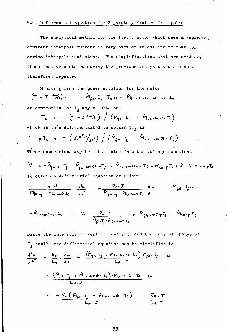
k.k D i f f e r e n t i a l Equation for Separately E x c i t e d I n t e r p o l e s
The a n a l y t i c a l method for the t . a . c . motor which uses a separate,
constant i n t e r p o l e c u r r e n t i s very s i m i l a r i n o u t l i n e to that for
s e r i e s i n t e r p o l e e x c i t a t i o n . The s i m p l i f i c a t i o n s that are used are
those that were s t a t e d during the previous a n a l y s i s and are not,
t h e r e f o r e , repeated.
S t a r t i n g from the power equation for the motor
an e x p r e s s i o n for I may be obtained
which i s then d i f f e r e n t i a t e d to obtain p i . as A
These expre s s i o n s may be s u b s t i t u t e d i n t o the voltage'equation •
V) : u \ - -sme-pTp - M£„.s,«e.u-Tc +Mi B.pl£+ *?« -T« - LB.fr«
to obtain a d i f f e r e n t i a l equation as before
Since the i n t e r p o l e c u r r e n t i s constant, and the r a t e of change of
1^ s m a l l , the d i f f e r e n t i a l equation may be s i m p l i f i e d to
35

T h i s i s a d i f f e r e n t i a l equation of the form
where
£p / 2 - LB
and i t i s noted that the damping term depends only upon the r e s i s t a n c e
and inductance of the armature c i r c u i t . I t does not depend upon the
mutual coupling between the i n t e r p o l e and armature windings, the speed
or the angle by which the average armature a x i s p o s i t i o n i s d i s p l a c e d
from the quadrature a x i s . To any p a r t i c u l a r parameter change, the
motor speed w i l l have a f i n a l steady s t a t e v a l u e . The degree of
damping w i l l however depend upon the other terras i n the above
d i f f e r e n t i a l equation.
36

Chapter 5 Comparison of Computed and Experimental
C h a r a c t e r i s t i c s
5.1 The Computer Programme
The programme uses the voltage and power equations which were
developed i n Chapter 2. I n o u t l i n e , the programme f i r s t c a l c u l a t e s
the s a t u r a t i o n e f f e c t s of the v a r i o u s c u r r e n t s flowing i n the c o i l s
and a d j u s t s the values of the s e l f and mutual inductances a c c o r d i n g l y .
Using the equation for the short c i r c u i t e d c o i l the time of
commutation i s obtained which, together with the speed of r o t a t i o n ,
enables the average value of © to be c a l c u l a t e d . The voltage and
power equations are r e w r i t t e n i n the form
d ( z ) / dt = func t i o n ( voltage, c u r r e n t , speed, e t c . )
and the r a t e s of change of current and speed are evaluated. From
the present values and the r a t e s of change, an i n t e g r a t i o n method
can compute new va l u e s of current and speed. These v a l u e s are then
used to obtain new r a t e s of change. By r e p e a t i n g the process, the
machine's performance may be c a l c u l a t e d .
The accuracy of the s i m u l a t i o n depends, obviously, upon the
accuracy of the numerical values used for the parameters of the
machine. I t a l s o depends upon the type of i n t e g r a t i o n proceedure.
A simple slope method u s i n g a large step length w i l l not be as
accurate as say, a fourth or f i f t h order, v a r i a b l e step method that
c o n t a i n s an e r r o r checking r o u t i n e . The computing time required for
the s i m u l a t i o n w i l l be g r e a t l y a f f e c t e d by the type of i n t e g r a t i o n
method that i s used.
The programme vyas w r i t t e n to be run under the c o n t r o l of CSMP
- Continuous Systems Modelling Program - which i s a general programme
developed s p e c i f i c a l l y f o r the dynamic modelling of systems.
37

5.2 Steady S t a t e Comparisons
The generator c h a r a c t e r i s t i c s were c a l c u l a t e d from a programme
s i m i l a r to that descibed i n Appendix B. The p r e d i c t e d open c i r c u i t
c h a r a c t e r i s t i c was about 5% higher than that measured on the t . a . c .
machine - Figure 5.1. The shape of the computed and measured curves
were extremely s i m i l a r . Also very s i m i l a r were the computed and
measured r e g u l a t i o n curves of the generator as shown i n Figure 5*2.
The p r e d i c t e d curve was again 3% higher than the measured c h a r a c t e r
i s t i c .
The 3% e r r o r may be a t t r i b u t e d to the approximations made during
the d e r i v a t i o n of the voltage and power equations. The values of the
slope of the inductance c o e f f i c i e n t s were measured or c a l c u l a t e d at
the p o s i t i o n ©=0°. At d i f f e r e n t v a l u e s of 0, the slope may change
s l i g h t l y . For example, the voltage waveform during the periods of
commutation and s l i p r i n g operation p r e d i c t e d by the computer were
more peaked than those observed on the experimental machine. I n
Figure 5«3 waveform ( a ) shows the experimental machine voltage wave
form and (b) i s the waveform from the computer. The average value
of the computed curve i s some h% higher than that observed. I f the
v a r i a t i o n of the slope over the range of 8 i s used and not j u s t i t s
average value a t 9=0°, then the computed waveform becomes l e s s peaked
and i t s average value i s w i t h i n 1% of the experimental curve - Figure
5-3 ( c ) . Unfortunately, to i n c l u d e t h i s kind of d e t a i l i n the
computer programme would s i g n i f i c a n t l y i n c r e a s e the computing time
n e c e s s a r y to perform the s i m u l a t i o n of the machine's performance.
I t must be remembered that a l l the inductances were measured
with the r o t o r s t a t i o n a r y and i t i s only to be expected that some
m o d i f i c a t i o n of the inductance waveforms would occur when the armature
i s r o t a t i n g under normal operating c o n d i t i o n s . With these f a c t s i n
58

Armature Voltage - v o l t s 200 H
150 H
100 H
50 -\
computed
— r -
50 - I — 100
measured
T T I 150 200 250
F i e l d c u r r e n t - mA
F i g . 5.1 Open C i r c u i t C h a r a c t e r i s t i c of Generator
Armature Voltage - v o l t s 200 H
180
160 -
140H
computed
T 5
n 1 r 10 15 20
Armature c u r r e n t - A.
F i g . 5.2 Regulation C h a r a c t e r i s t i c of Generator
39

<b in
LU
O O
C71
(0
CO
in
«0 yi (0 CO
UJ CD
> w CN UJ O cn
M o ID CO CN CD CM CNI
40

mind, the accuracy with which the computer model p r e d i c t e d the
generator c h a r a c t e r i s t i c s i s considered s u f f i c i e n t f o r the model to
be used to study the t r a n s i e n t behaviour of the t . a . c . motor.
The steady s t a t e c h a r a c t e r i s t i c s of the motor were c a l c u l a t e d
and compared to those obtained experimentally. The speed - f i e l d
c u r r e n t c h a r a c t e r i s t i c for the s e r i e s i n t e r p o l e machine i s shown i n
F i g u r e 5-4: curve ( a ) being experimental, curve (b) computed. The
speed-load c u r r e n t c h a r a c t e r i s t i c i s given i n Figure 5»5: again ( a )
i s experimental and curve (b) computed. The 3% d i f f e r e n c e between
the computed and experimental c h a r a c t e r i s t i c s i s again apparent but
of more importance i s the great s i m i l a r i t y between them. Under weak
f i e l d and l i g h t load c o n d i t i o n s both the computer model and the
experimental motor e x h i b i t the same kind of o s c i l l a t o r y performance.
5*3 T r a n s i e n t Comparisons
As a t e s t of the model under changing c o n d i t i o n s the s e l f
e x c i t a t i o n curve of the generator and the s t a r t i n g performance of the
motor were simulated. Figure 5-6 gives the measured and computed
s e l f e x c i t a t i o n curve and, to w i t h i n 4%, the computer has s u c c e s s f t i l l y
p r e d i c t e d the output voltage. The" sTarTxng perfbrmance oT the motor
i s shown i n Figure 5*7 and again the computer has simulated the
machine f a i r l y a c c u r a t e l y . Below a speed of 60 rps the r e s u l t s are
not t o t a l l y v a l i d because of the method of determining the time of
commutation. T h i s method i s d i s c u s s e d i n Appendix B. Nevertheless,
the model p r e d i c t e d the motor speed to w i t h i n 3% of the measured
v a l u e s over the speed range of 0 to 120 r p s .
The responses of the motor to a. step change i n one of the
parameters were recorded on the experimental machine and then compared
to a s i m u l a t i o n of the same change. The step disturbance applied to
41

Speed - rev/min 2 5 0 0 -
2 2 5 0 -
2 0 0 0 -
1 7 5 0 -
•b' computed
= o s c i l l a t o r y
zone
—i 1 1 1 r 100 150 200 250 300
F i e l d c u r r e n t - mA.
F i g . 5 . ^ Speed - F i e l d Current C h a r a c t e r i s t i c of Motor
2500 Speed - rev/min
2 2 5 0 -
2 0 0 0 - o s c i l l a t o r y zone
•b' computed
measured
10 1
15 20
Armature c u r r e n t - A.
F i g . 5 .5 Speed - Armature Current C h a r a c t e r i s t i c of Motor
! 1+2

Armature Voltage - v o l t s
200 H
100 H computed
measured
0 2 if 6 8
Time - seconds
F i g . 5 . 6 S e l f e x c i t a t i o n C h a r a c t e r i s t i c of Generator
Speed - radians/second 200-J
160
120
computed
80 measured
I 20 25
Time - seconds
F i S - 5 . 7 Speed Run-up of T.A.C. Motor

b o t h t h e machine and model was t h a t o f s w i t c h i n g out a r e s i s t o r o f
3 ohms i n the armature c i r c u i t . Under l i g h t r u n n i n g c o n d i t i o n s the
a rmature c u r r e n t was n o m i n a l l y 2 . 5 A so t h a t 7 » 5 V were dropped
a c r o s s t h e r e s i s t o r . S h o r t i n g out t h e r e s i s t o r causes the armature
t o see a s t e p i n c r e a s e o f 7-5 v o l t s .
The response o f t h e machine speed and armature c u r r e n t t o the
above change was r e c o r d e d a t f o u r d i f f e r e n t l e v e l s o f f i e l d c u r r e n t .
I n each case the i n t e r p o l e w i n d i n g was s e r i e s connected w i t h the
a r mature and t h e t . a . c . machine was m e c h a n i c a l l y coupled t o the
dynamometer. At maximum f i e l d c u r r e n t ( i . e . minimum speed) the
response was t h a t o f a w e l l damped system - F i g u r e 5-8 ( a ) . The
computer s i m u l a t i o n f o r the same c o n d i t i o n s gave a more r a p i d i n i t i a l
i n c r e a s e i n the c u r r e n t waveform b u t a f t e r 0 . 2 seconds, t h e waveforms
matched c l o s e l y - g e n e r a l l y t o w i t h i n -3%. As t h e f i e l d c u r r e n t was
r e d u c ed and t h e n o m i n a l motor speed i n c r e a s e d , t h e responses o f b o t h
t h e motor and model.became underdamped and e v e n t u a l l y , c o n t i n u o u s
speed o s c i l l a t i o n s were o b t a i n e d . F i g u r e s 5*8 ( b ) t o ( d ) show t y p i c a l
r e s p o n s e s as t h e f i e l d c u r r e n t i s reduced. Only the c u r r e n t waveforms
are shown as these gave a more c r i t i c a l t e s t of m a t c h i n g .
B e f o r e d i s c u s s i n g these r e s u l t s , two more t e s t s o f t h e machine
and model are g i v e n . The f i r s t i s t h e response t o t h e above s t e p
change o f v o l t a g e but w i t h t h e armature c u r r e n t a t i t s r a t e d v a l u e -
F i g u r e 5*9 ( a ) . Secondly, the response o f t h e motor t o t h e removal
o f a l o a d t o r q u e i s g i v e n i n F i g u r e 5»9 ( b ) . Around the r a t e d c u r r e n t
t h e responses were s t a b l e b u t o s c i l l a t i o n s were a g a i n produced when
th e l o a d t o r q u e was removed and t h e motor l e f t t o r u n under l i g h t
l o a d c o n d i t i o n s . The computer s i m u l a t i o n s agreed c l o s e l y w i t h the
e x p e r i m e n t a l measurements.

Armature Current amperes
8 computed measured
o H 1 1 i 1 r 0 2 *f 6 8 10
Time - seconds
( a ) Motor Current Response - I f = 0 . 2 5 0 ampere
Armature Current - amperes 10 -
8 computed measured
0 2 k 6 8 10
Time - seconds
(b) Motor Current Response - I - = 0 . 225 ampere
F i g . 5 .8 (a,b) Motor Current Responses
^5

Armature Current - amperes
computed measured
8
i 8 10
Time second
( c ) . Motor Current Response - I 0.200 ampere
Armature c u r r e n t - amperes 12
measured
\ 8
0 2 4 6 8 10
Time - seconds
(d) Motor Current Response - 1 . = 0 .175 ampere
F i g . 5 .8 (c,d) Motor Current Responses
k6

Armature Current - amperes 1 6-J
computed
T i _ J 10 measured
8
8 10
Time seconds
(a) . Motor Current Response - I 0.1y5am vere
Armature Current - amperes
12-J
computed measured
Time - seconds
(b) Motor Current Response - I f = 0 .175 ampere
F i g . 5 . 9 Motor Current Responses

5 . ^ D i s c u s s i o n on t h e Computer Model
The v o l t a g e and power e q u a t i o n s have been s a t i s f a c t o r i l y developed
i n t o a computer programme capable o f p r e d i c t i n g the performance o f
the machine over a wide range o f steady s t a t e and t r a n s i e n t c o n d i t i o n s .
The computer model does i n some cases p r e d i c t t h a t the motor w i l l
o s c i l l a t e c o n t i n u o u s l y whereas t h e e x p e r i m e n t a l motor does have a
f i n a l s t e a d y speed. Computer s t u d i e s have shown t h a t t h e response
o f t h e motor i s p a r t i c u l a r l y s e n s i t i v e t o changes o f a n g l e and s a t u r a t i o n
c r i t e r i a . A d i f f e r e n c e o f 2 ° can s i g n i f i c a n t l y a l t e r t h e f o r m o f
response as i s shown i n F i g u r e 5 « 1 0 . At an angle o f 0 = - 8 ° t h e
response i s underdamped and o s c i l l a t o r y b u t a t © = - 6 ° , t h e response
i s c r i t i c a l l y damped. A change i n the s t a r t i n g p o s i t i o n o f commutation
by as l i t t l e as 1 ° can a l t e r t h e ma t c h i n g o f the r e s u l t s . At 1800
r e v / m i n , a time d e l a y o f 0 . 1 mS was e q u i v a l e n t t o the r o t o r moving
t h r o u g h an angle o f 1 ° . The d e s i g n o f t h e f i r s t t r i g g e r i n g c i r c u i t
was such t h a t t i m e d e l a y s o f t h i s magnitude were f e a s i b l e . S a t u r a t i o n
e f f e c t s may a l s o p r e v e n t a c c u r a t e m a t c h i n g and as a t e s t o f the
s e n s i t i v i t y o f the model, a s i m u l a t i o n was r e p e a t e d u s i n g d i f f e r e n t
s a t u r a t i o n c r i t e r i a . The e f f e c t o f a -3% change i n the maximum v a l u e A'
o f ( a t 1 . ^ = 2 A.) can be c l e a r l y seen i n F i g u r e 5 « H . Curve ( c )
was o b t a i n e d u s i n g t h e s a t u r a t i o n curve o f F i g u r e 3 .3 ( b ) w h i l e c u r v e s
( f ) and ( g ) were produced by t h e above +3% and -3% d i s p l a c e m e n t s
r e s p e c t i v e l y . Curve ( f ) i s o s c i l l a t o r y b u t curve ( g ) i s overdamped.
N e v e r t h e l e s s , the model may be used t o d i s t i n g u i s h those areas
o f o p e r a t i o n i n which the performance of t h e motor i s u n d e s i r a b l e
f r o m t h e p o i n t o f view o f s t a b i l i t y . The model can p r e d i c t t h e
performance o f the t . a . c . machine w i t h s u f f i c i e n t a c c u r a c y over a
wide range o f o p e r a t i n g c o n d i t i o n s .
*f8

Speed radians/second
260
2*f0
8*
220
/ 200 average armature a x i s p o s i t i o n
180
i 6 8 10
Time seconds
F i g . 5 . 1 0 Motor Speed Responses - C r i t i c a l dampirig
<f9

radians/second Speed
260
i f f 2hO g
220
200
i 8
Time seconds
F i g . 5 . 1 1 Motor Speed Responses - Small S a t u r a t i o n Changes
50

5 . 5 Commutating A b i l i t y o f Machine
At low speeds (below 50 r e v / m i n ) and a t s t a r t i n g t h e i n t e r p o l e
i n d u c e d v o l t a g e i s i n s u f f i c i e n t t o ensure complete commutation o f
the a r mature c u r r e n t . Commutation i s completed by t h e brushes as i n
a c o n v e n t i o n a l d.c. machine. D u r i n g t h i s p e r i o d the commutation
process i s u s u a l l y accompanied by s l i g h t s p a r k i n g a t t h e t r a i l i n g
edge o f the br u s h e s . To d e t e r m i n e the speed range over w h i c h t h e
t . a . c . machine can operate i t i s necessary t o be a b l e t o compute the
commutating a b i l i t y o f the machine. That i s , t o be a b l e t o compute
the range over which the i n t e r p o l e induced v o l t a g e i s always
s u f f i c i e n t t o commutate the c u r r e n t i n the armature b e f o r e the
b r u s h l e a v e s t h e segment.
T h i s range may be c a l c u l a t e d b y . u s i n g the v o l t a g e e q u a t i o n f o r •
the a r mature s h o r t e d t u r n s -
( s e r i e s i n t e r p o l e e x c i t a t i o n )
The t i m e r e q u i r e d f o r the r e v e r s a l o f the armature c u r r e n t i s
e v a l u a t e d and compared t o t h e t i m e between the s t a r t o f each
commutation p e r i o d . The maximum r a t i o o f these two t i m e s depends
upon t h e b r u s h - segment geometry and i s g i v e n by ( s - 2 b ) / s where s
i s the segment arc and b the brush a r c .
The commutating a b i l i t y o f t h e e x p e r i m e n t a l machine was computed
from the above e q u a t i o n and i s g i v e n i n F i g u r e 5 .12 f o r two v a l u e s
o f armature c u r r e n t . The maximum r a t i o i s 0 . 71 f o r the machine and
from the c u r v e s , the machine s h o u l d be a b l e t o commutate s a t i s f a c t o r i
down t o about 35 r e v / m i n . I n p r a c t i c e , s l i g h t s p a r k i n g was observed
up t o about *f0 - 45 r e v / m i n .
51

0.k5 ~
O.kO -
0 . 3 5 "
0 . 3 0 -
0 . 2 5 -
0 . 2 0 -
0 . 1 5 '
commutation time commutation + s l i p r i n g time
Z 0 . 0
0 50
Armature c u r r e n t = 10 A.
Armature c u r r e n t = 3 A.
I 1 1 100 150 200
Speed ( r a d i a n s / s e c o n d )
F i g . 5*12 Computed Commutating A b i l i t y o f Motor
( s e r i e s i n t e r p o l e )
52

Chapter 6 D i s c u s s i o n on the Speed O s c i l l a t i o n s
6 . 1 Comparison w i t h C o n v e n t i o n a l Machines
(6 1)
M o u l l i n * d i s c u s s e s t h e p o s s i b i l i t y o f speed o s c i l l a t i o n s
o c c u r i n g i n c o n v e n t i o n a l d.c. machines and shows t h a t a prime cause
i s t h e demagnet i s i n g e f f e c t o f t h e armature mmf• T h i s causes the
motor speed t o r i s e w i t h i n c r e a s i n g armature c u r r e n t i f t h e machine
i s o p e r a t i n g under such c o n d i t i o n s t h a t t h e speed r i s e s w i t h d e c r e a s i n g
f i e l d f l u x . The motor thus has a r i s i n g speed c h a r a c t e r i s t i c .
Should t h e armature c u r r e n t i n c r e a s e f o r any reason, the t o r q u e
developed w i l l be i n excess o f the l o a d r e q u i r e m e n t and the system
w i l l be a c c e l e r a t e d . T h i s i n c r e a s e o f speed causes more armature
c u r r e n t t o f l o w w h i c h , i n t u r n , i n c r e a s e s t h e speed s t i l l f u r t h e r .
The speed and c u r r e n t t e n d t o r i s e towards i n f i n i t y u n t i l , t h e motor
p r o t e c t i n g d e v i c e s ( e . g . f u s e ) p r e v e n t any f u r t h e r i n c r e a s e . However,
i f t h e l o a d t o r q u e a l s o i n c r e a s e s w i t h speed i t w i l l t e n d t o c o u n t e r
a c t t h e r i s i n g n a t u r e and i t i s f e a s i b l e f o r the motor t o h u n t about
a f i x e d speed. The h u n t i n g i s c l e a r l y dependent upon the motor and
l o a d t o r q u e c h a r a c t e r i s t i c s and a r i s i n g c h a r a c t e r i s t i c i s necessary.
I n t h e t . a . c . machine, the armature a x i s may be c o n s i d e r a b l y
d i s p l a c e d from t h e n e u t r a l a x i s and the d e m a g n e t i s i n g e f f e c t o f t h e
a r m a t u r e mmf w i l l be c o n s i d e r a b l y l a r g e r . W i t h the a x i s d i s p l a c e d
f r o m t h e n e u t r a l a x i s speed and c u r r e n t o s c i l l a t i o n s were r e c o r d e d
i n t h e e x p e r i m e n t a l machine w i t h s e r i e s connected i n t e r p o l e s . H u n t i n g
c o u l d o c c u r f o r the same reasons as above b u t i n the e x p e r i m e n t a l motor
i t was s a t u r a t i o n and not l o a d t o r q u e r e q u i r e m e n t s t h a t p r e v e n t e d
e x c e s s i v e speeds and c u r r e n t s . I n i t i a l l y , t h e speed and c u r r e n t r i s e
as d e s c r i b e d above but e v e n t u a l l y s a t u r a t i o n p r e v e n t s the armature
mmf f r o m any f u r t h e r p r o p o r t i o n a l i n c r e a s e and the c u r r e n t b e g i n s
53

t o f a l l as t h e speed approaches t h e v a l u e s e t by the o v e r a l l f l u x .
As the c u r r e n t f a l l s , the d e m a g n e t i s i n g mmf becomes s m a l l e r t e n d i n g
t o slow t h e motor. The motor t h u s r e q u i r e s l e s s c u r r e n t . The process
i s c u m u l a t i v e and the speed and c u r r e n t reduce s t i l l f u r t h e r .
E v e n t u a l l y the c u r r e n t f a l l s t o zero where i t i s p r e v e n t e d f r o m g o i n g
n e g a t i v e by t h e diode a c t i o n o f t h e t h y r i s t o r s . The speed f a l l s due
t o l o a d and f r i c t i o n a l t o r q u e s u n t i l the t h y r i s t o r s become f o r w a r d
b i a s e d and t h e c y c l e r e p e a t s .
The cause o f h u n t i n g i s s i m i l a r i n the t . a . c . machine and i n
c o n v e n t i o n a l machines and i s due t o a r i s i n g speed-torque c h a r a c t
e r i s t i c produced by t h e d e m a g n e t i s i n g e f f e c t o f the armature mmf.
The e f f e c t s are l i k e l y t o be more pronounced i n the t . a . c . machine
because o f t h e g r e a t e r d i s p l a c e m e n t between the armature and n e u t r a l
axes.
6 . 2 Methods o f P r e v e n t i o n o f Speed O s c i l l a t i o n
The d e m a g n e t i s i n g e f f e c t s o f t h e armature mmf may be compensated
by i n c l u d i n g an e x t r a w i n d i n g on t h e f i e l d system o f a c o n v e n t i o n a l
machine. T h i s w i n d i n g i s s e r i e s connected w i t h the armature and
produces a m a g n e t i s i n g f l u x t h a t j u s t c o u n t e r a c t s the d e m a g n e t i s i n g
amature f l u x . The r i s i n g c h a r a c t e r i s t i c does not then occur and
h u n t i n g i s p r e v e n t e d . Such a w i n d i n g may a l s o be used i n t h e t . a . c .
machine b u t , f o r e x a c t compensation, the s t r e n g t h o f t h e compensating
w i n d i n g would be dependent upon the r e l a t i v e p o s i t i o n o f t h e armature
a x i s . A l t h o u g h t h i s w i n d i n g c o u l d be designed t o p r e v e n t o s c i l l a t i o n
o f t h e motor speed i t c o u l d a l s o produce a severe droop i n t h e speed
t o r q u e c u r v e i f the armature a x i s p o s i t i o n was behind the n e u t r a l a x i s .
Such a method i s h a r d l y s a t i s f a c t o r y and o t h e r methods o f p r e v e n t i n g
o s c i l l a t i o n s were c o n s i d e r e d .
5h

I n Chapter k t h e e q u a t i o n o f m o t i o n o f t h e t . a . c . motor u s i n g
overwound, s e r i e s e x c i t e d i n t e r p o l e s had the approximate form
or
where ^ i s t h e damping f a c t o r and i s
The response o f the motor depends upon the n u m e r i c a l v a l u e o f IS and
as l o n g as y has a p o s i t i v e v a l u e , no m a t t e r how s m a l l , a. s t e a d y s t a t e
r e s u l t w i l l always be o b t a i n e d . The f i r s t c o n d i t i o n f o r a f i n a l
s t e a d y s t a t e speed i s
Riff •* 2 • M i f l • 3m © • u> > o
I f 2T>^Ojthe response i s v e r y overdamped and as 2T i s reduced t h e
response becomes p r o g r e s s i v e l y l e s s damped u n t i l , a t 6 = 0 , c o n t i n u o u s
o s c i l l a t i o n s w i l l occur - t h e r e b e i n g no damping p r e s e n t . T a k i n g as
the l i m i t i n g case 0= 0 , the v a r i a t i o n o f speed w i t h a n g u l a r d i s p l a c e
ment ( 0 ) o f t h e armature and n e u t r a l axes was of t h e form o f a
r e c t a n g u l a r h y p e r b o l a - F i g u r e 6 . 1 . The l i m i t i n g boundary depended
upon t h e magnitude o f the armature r e s i s t a n c e and the armature and
i n t e r p o l e c u r r e n t . S t a b l e o p e r a t i o n was o b t a i n e d i f the o p e r a t i n g
p o i n t l a y below the r e s p e c t i v e boundary. For s t a b l i t y a t h i g h speeds
a low v a l u e o f Q was r e q u i r e d and v i c e v e r s a .
The c o n d i t i o n f o r s t a b i l i t y as g i v e n by the above e x p r e s s i o n
55

Speed - radians/second
1200
\
1000
800
600
\ koo
200
1 1 1 1 1 1 0 - 0 . 0 5 - 0 . 1 - 0 . 1 5 - 0 . 2 - 0 . 2 5
SIN(S)
1 armature r e s i s t a n c e 2 . 6 ohms, armature c u r r e n t 2 A
2 armature r e s i s t a n c e 2 .6 ohms, armature c u r r e n t 10A
3 armature r e s i s t a n c e 6.0 ohms, armature c u r r e n t 2 A k armature r e s i s t a n c e 6.0 ohms, armature c u r r e n t 10 A
F i g . 6.1 L i m i t i n g Speeds for n o n - o s c i l l a t o r y responses
56

may be p l o t t e d as a s i n g l e s t r a i g h t . l i n e boundary as shown as l i n e
'a' i n F i g u r e 6 . 2 . S t a b l e o p e r a t i n g p o i n t s l i e above and t o the l e f t
o f t h i s l i n e ; u n s t a b l e p o i n t s t o t h e r i g h t and below the l i n e . The
degree o f s t a b i l i t y o f an o p e r a t i n g p o i n t may be judged by i t s
d i s t a n c e f r o m the l i n e . A v e r y overdamped s t a b l e response w i l l be
i n t h e upper l e f t o f the f i g u r e whereas a damped b u t o s c i l l a t o r y
response w i l l be j u s t above the l i n e .
T y p i c a l l o c i o f s t a b l e responses - l o c i ' e' and ' f - and o f
u n s t a b l e o r o s c i l l a t o r y responses - l o c i ' r ' and 's' - were p l o t t e d
on F i g u r e 6 . 2 . The s t a b l e responses crossed the boundary i n t o the
u n s t a b l e r e g i o n as g i v e n by t h e e x p r e s s i o n s above. I t i s p o s s i b l e
t o c o n s t r u c t a m o d i f i e d boundary - l i n e 'b* - such t h a t s t a b l e p o i n t s
e x i s t e d o n l y t o t h e l e f t o f t h i s new l i n e w h i l e the l o c i o f u n s t a b l e
or o s c i l l a t o r y responses e x i s t e d i n b o t h r e g i o n s . The m o d i f i e d
boundary always l i e s t o the r i g h t o f , and below t h a t g i v e n by the
damping t e r m i n the approximate e q u a t i o n o f m o t i o n . I t i s o n l y
p o s s i b l e t o c o n s t r u c t the m o d i f i e d boundary from t h e r e s u l t s o f
e i t h e r p r a c t i c a l measurements or from a s i m u l a t i o n o f t h e motor.
6.3 D i s c u s s i o n o f the S t a b i l i t y C r i t e r i a
The i n c l u s i o n o f more terms i n t o the e q u a t i o n o f m o t i o n o f
the motor would t e n d t o move the m o d i f i e d boundary n e a r e r t o t h a t
p r e d i c t e d by the t h e o r y . The approximate e q u a t i o n does n o t account
f o r i n t e r a c t i o n between the v o l t a g e s and c u r r e n t s o f the f i e l d and
armature c i r c u i t s . For example, t h e r e i s a s l i g h t t r a n s f o r m e r
c o u p l i n g between t h e f i e l d and armature which i m p a r t s t o the motor
a b e t t e r performance t h a n t h a t t h a t would be p r e d i c t e d by t h e s i m p l e
e q u a t i o n . The e f f e c t of t h i s c o u p l i n g may be observed by s i m u l a t i n g
on t h e computer model the responses o f the motor w i t h and w i t h o u t t h i s
57

Armature Resistance 2 . M- „ . speed i . a r
0.25 "
STABLE
0.20
e
s
0.10
0.05
UNSTABLE
0.25 0.05
SIN(Q)
e, f l o c i of st a b l e responses r , s l o c i of unstable responses
F i g . 6 . 2 Stable and Unstable Operating Zones
58

coupling term included. Without the term the o s c i l l a t i o n s were of
a higher frequency and of a d i f f e r e n t waveshape compared t o those
obtained w i t h the term included. I n Figure 6 . 3 the i n c l u s i o n of t h i s
term p r e d i c t s t h a t a steady s t a t e r e s u l t w i l l e v e n t u a l l y be obtained
whereas w i t h o u t i t , the model p r e d i c t s t h a t the motor speed w i l l
continuously o s c i l l a t e .
There are other terms t h a t are not included i n the simple
d i f f e r e n t i a l equation and which also a f f e c t the o v e r a l l response.
Nevertheless, the use of t h i s simple equation and of the average
values of the motor parameters can give an i n d i c a t i o n of the
l i k l i h o o d of stable operation.
59

Speed - radians/second
260 ~
2^0 -
220 -
200-
f i e l d c u r r e n t v a r i a b l e
f i e l d c u r r e n t f i x e d
I 8
1^ 12
"T -
16 Time - seconds
( a )
Speed - radians/second
260-
2*f0-
220-
200-
f i e l d c u r r e n t v a r i a b l e
— r 20
f i e l d c u r r e n t f i x e d
T 8 12
Time 16
seconds
— r 20
(b)
F i g . 6 . 5 Motor Speed Responses - E f f e c t of Coupling Term
between armature and f i e l d windings
60

Chapter 7 C o n t r o l of the T.A.C. Machine by Delayed
T h y r i s t o r F i r i n g
7 . 1 E f f e c t of Delayed T h y r i s t o r F i r i n g
For a l l commutator machines i t i s a general r u l e t h a t the
d i r e c t i o n of the armature mmf and f l u x i s determined by the p o s i t i o n
of the brushes on the commutator. I f the brushes are displaced from
the n e u t r a l a x i s by an angle &, the armature axis would also be
displaced by t h i s angle. The t o t a l f l u x now a c t i n g on the armature
i s a combination of the f i e l d and the i n t e r p o l e f l u x e s . Depending
upon the p o s i t i o n s of the brushes and the mode of operation of the
machine, the i n t e r p o l e f l u x c o n t r i b u t i o n may a s s i s t or d e t r a c t from
the main p o l a r f l u x . I n conventional machines i t i s the commutation
process t h a t d i c t a t e s t h a t the brush p o s i t i o n s be r e s t r a i n e d close
to the n e u t r a l or quadrature a x i s .
With t h y r i s t o r a s s i s t e d commutation, the commutation process i s
not performed by the brushes. These only act as a means of passing
current i n t o and out of the armature winding. As long as the c u r r e n t
i n part of the armature i s reversed before the brush leaves an a c t i v e
segment, there w i l l be no sparking at the brushes. The use of an
overwound i n t e r p o l e , a separately e x c i t e d i n t e r p o l e or even p a r t of
the main f i e l d pole can a l l b r i n g about commutation. There i s , there
f o r e , no reason why the output of the machine cannot be c o n t r o l l e d ,
at l e a s t over a. l i m i t e d range, by s h i f t i n g the p o s i t i o n of the
armature a x i s away from the n e u t r a l a x i s .
7 . 2 P r a c t i c a l Method of Moving Axis
The displacement of the armature axis from the n e u t r a l a x i s may
be achieved i n one of two ways. The f i r s t i s t o a l t e r the time of
61

commutation and the second i s to change the angle at which the
commutation process s t a r t s . I f the time of commutation i s made
v a r i a b l e by a l t e r i n g the stren g t h of the i n t e r p o l e current then i t
i s not possible f o r the average armature axis p o s i t i o n t o be behind
the n e u t r a l a x i s . By d e f i n i t i o n , commutation i s deemed to be t a k i n g
the whole of the a v a i l a b l e angle when the average axis p o s i t i o n l i e s
along the n e u t r a l a x i s . For the a x i s to be behind the n e u t r a l a x i s
commutation must be t a k i n g more than the a v a i l a b l e angle and sparking
at the brushes w i l l , most c e r t a i n l y , be seen.
I f the angle of commutation i s made small (20% of the maximum
angle) then by c o n t r o l l i n g the s t a r t of t h i s small commutation band
the average armature ax i s p o s i t i o n can vary over a f a i r l y wide range
about the n e u t r a l a x i s . Since the band i s small, sparking w i l l not
occur unless the s t a r t of the band i s so near the end of a segment
t h a t commutation i s not completed before the brush leaves the segment.
With a s e r i e s connected i n t e r p o l e the degree of overwinding was not
s u f f i c i e n t t o make the angle of commutation very small. By using a
constant, separate i n t e r p o l e e x c i t a t i o n a small commutation band
could be obtained f o r l i g h t loads (O.k rated and below) thus enabling
a p r e l i m i n a r y i n v e s t i g a t i o n of the method to be made. The l i m i t a t i o n s
caused by lo a d i n g e f f e c t s are discussed i n a l a t e r s e c t i o n .
A p r a c t i c a l method of s h i f t i n g the armature axis i s to use
r a p i d commutation and to adjust the s t a r t i n g p o s i t i o n of the commut
a t i o n process. The brushes were l e f t p h y s i c a l l y along the n e u t r a l
a x i s b u t , by t r i g g e r i n g the t h y r i s t o r s only a v a r i a b l e time delay,
t h e i r e f f e c t i v e p o s i t i o n s could be r e a d i l y changed. Tjae armature
axi s p o s i t i o n i s being changed by e l e c t r o n i c a l l y rocking the brushes
by delayed t h y r i s t o r f i r i n g .
62

7 . 3 Motor C h a r a c t e r i s t i c s - L i g h t Loadings
For steady s t a t e , l i g h t load conditions the speed - f i e l d
c u r r e n t c h a r a c t e r i s t i c s are shown i n Figure 7 . 1 . Figure 7 . 1 (a)
i s f o r s e r i e s e x c i t e d i n t e r p o l e s and at low f i e l d c u r r e n t s , the
steady s t a t e speed w i t h minimum delay time degenerates i n t o a
continuous o s c i l l a t i o n about a mean value. The speed response of
the motor depended upon both the delay time and the value of the
f i e l d c u r r e n t . The delay time a l t e r s the r e l a t i v e p o s i t i o n of the
armature a x i s and the kind of speed responses are very s i m i l a r to
those shown and discussed i n chapters k and 5«
Figure 7 . 1 (b) shows the speed - f i e l d current response f o r the
motor w i t h a separately e x c i t e d i n t e r p o l e ( 1 ^ = 1 0 A). The range
of c o n t r o l was much greater than t h a t obtainable w i t h s e r i e s e x c i t a t i o n
but t h i s must be q u a l i f i e d by the e f f e c t s of loading which w i l l be
discussed i n the next s e c t i o n . The speed response of the motor w i t h
separate e x c i t a t i o n was overdamped f o r a l l values of delay time.
U n f o r t u n a t e l y , w i t h separate e x c i t a t i o n , the maximum armature current
i s l i m i t e d t o a value some 1.^ times the i n t e r p o l e c u r r e n t . To exceed
t h i s value would cause, sparking owing t o commutation f a i l u r e . To keep
w i t h i n t h i s f i g u r e large step changes must.be made i n two steps and
the response time becomes much longer.
The l i n e a r i t y between the input voltage to the t h y r i s t o r delay
c o n t r o l u n i t (chapter 8 ) i s given i n Figure 7 . 2 . Over the range
i n d i c a t e d i n the f i g u r e , a l i n e a r i t y of 2% or b e t t e r was obtained
using separate i n t e r p o l e e x c i t a t i o n but of only 5% using s e r i e s
i n t e r p o l e e x c i t a t i o n . A reason f o r t h i s i s the much smaller and
more w e l l defined zone of commutation obtained by using separate
e x c i t a t i o n .
63

( a ) S e r i e s I n t e r p o l e E x c i t a t i o n
2500H Speed
rev/min
2000H
150CH
o s c i l l a t o r y zone minimum time
maximum time delay
F i e l d Current - mA 1 1—
100 150 200 250
2500 H
Speed rev/rain
2000 H
1500 H
(b) Separate I n t e r p o l e E x c i t a t i o n (1 pu)
minimum time delay
maximum time delay
1000
F i e l d Current - mA
100 ~ 1 — 150
- 1 — 200 250
F i g . 7 . 1 Speed - F i e l d Current C h a r a c t e r i s t i c of Motor
6 k

2500
Speed - rev/min
2250
s e p a r a t e l y e x c i t e d i n t e r p o l e
2000
s e r i e s e x c i t e d i n t e r p o l e
1500
l i m i t of l i n e a r i t y
1250
20 10 20
Modulating Voltage v o l t s
F i g . 7 . 2 L i n e a r i t y of T.A.C. Motor C o n t r o l
65

7Effects of Loading on Motor Control
7 . ^ . 1 Commutation Angles
The previous sections i n d i c a t e d the. range of c o n t r o l possible
w i t h separate i n t e r p o l e e x c i t a t i o n when the motor was running on l i g h t
loads. This range cannot be obtained w i t h greater loadings because
of the l i m i t a t i o n s imposed by the commutation of the higher currents
and by the o v e r a l l speed-torque c h a r a c t e r i s t i c s of the motor. Figure
7 . 3 shows the measured commutation angle as a f u n c t i o n of the armature
cu r r e n t f o r a constant i n t e r p o l e current of 1 0 amperes. The commut
a t i o n angle was measured w i t h minimum and maximum f i r i n g delay times.
Minimum delay corresponds t o the t h y r i s t o r s being f i r e d as soon as
the brush i s f u l l y on the segment while maximum delay means t h a t the
f i r i n g , i s .delayed so tha t commu.tati.on. j u s t f i n i s h e s before any part
of the brush leaves the segment. The p o i n t s f o r maximum and minimum
delay a l l l i e about the same curve and by e x t r a p o l a t i n g the curve,
the maximum commutable current i s about 1 6 . 5 A. This value has been
confirmed by experiment. The commutation angle i s independent of
delay time but very dependent upon the armature c u r r e n t . For small
loads (say 3 A) commutation i s completed i n 2 ° a l l o w i n g the axi s t o
l i e w i t h i n the range ^ 1 5 ° around the n e u t r a l a x i s . At r a t e d current
t h i s range i s reduced to - 1 1 ° and above the rate d c u r r e n t , the range
f a l l s r a p i d l y to zero f o r a cur r e n t of 1 6 . 5 A.
7 . ^ . 2 Speed - Torque C h a r a c t e r i s t i c s
From the machine equations the steady s t a t e voltage and torque
f o r the experimental machine are
V . A A
a - Mffl-w-Tj * £fl-Ia -<- Mia • si« e-ui • T x
66

Commutation Angle - degrees
32H
28 J
2hJ
20 H
16H
12H
8J
0
^ e x t r a p o l a t i o n
0 12 1 6 " i — 20
Armature Current - Amperes
"—X——X— maximum f i r i n g delay
— • — — • — minimum f i r i n g delay
F i g . 7 » 3 Commutation Angle - Separate I n t e r p o l e E x c i t a t i o n
»a 13 JUN1972
6 7

With 9=0 , the speed - f i e l d c u rrent c h a r a c t e r i s t i c s f o r a range of
torque may be computed. Neglecting f o r the moment the r e s t r i c t i o n
t h a t only c u r r e n t s below 1 6 . 5 A can be commutated, Figure shows
the speed - f i e l d current c h a r a c t e r i s t i c s using t y p i c a l values of
the machine's parameters. At high torques ( - ^ 6 0 Nm) the speed f a l l s
as the f i e l d c u r r e n t i s reduced while at lower torques and high f i e l d
c u rrents the c h a r a c t e r i s t i c s have a r i s i n g nature. Also shown on the
f i g u r e i s the constant current l i n e of 1 6 . 5 A i . e . the maximum cu r r e n t
t h a t can be commutated. For the experimental machine, i t s speed -
f i e l d c u r r e n t c h a r a c t e r i s t i c i s of a r i s i n g nature over i t s normal
operating range.
Considering only t h i s range the e f f e c t of i n t r o d u c i n g the maximum
v a r i a t i o n of the armature axis p o s i t i o n was computed. The maximum
.v a r i a t i o n i s , of course, reduced at the higher torques in.accordance
w i t h the curve shown i n Figure 7 . 3 . Figure 7 » 5 gives the computed
speed - f i e l d current c h a r a c t e r i s t i c s f o r constant torques of 0 , 5
and 1 0 Nm. Figure 7 « 6 gives the speed - torque c h a r a c t e r i s t i c s f o r
constant f i e l d c urrents of 0 . 1 2 5 and 0 . 2 7 5 A. From these f i g u r e s ,
the range over which the motor speed may be c o n t r o l l e d depends upon
both the load torque r e q u i r e d and upon the f i e l d c u r r e n t . The
a v a i l a b l e speed range at rate d output i s 50 to 70% of t h a t a t l i g h t
or no-loads f o r the experimental machine.
Of p a r t i c u l a r note i s the large speed red u c t i o n w i t h load torque
using minimum delay and the small change w i t h maximum delay. This
occurs since the commutation angle increases at the higher c u r r e n t s
and the mean armature a x i s moves towards the n e u t r a l a x i s . The speed
torque c h a r a c t e r i s t i c s f o r minimum and maximum delay thus approach
those f o r the 'normal' machine. This can be c l e a r l y seen i n Figure
7 . 6 .
68

Jfoo A 1 6 Amp Constant Current
350 1
Speed rads/sec
250 1 Torque
200 ~
150 1
100 -1
- Nm.
150 200 250 3 0 0
F i e l d Current - mA.
Fi g . 7 . ^ Speed - F i e l d Current C h a r a c t e r i s t i c s of Motor
(Separate I n t e r p o l e E x c i t a t i o n )
69

Speed rad/sec
koo
\ \ \ 3 5 0
minimum delay \ 0 Nm 5 Nm \ 300 1 0 Nm
\
\ \ 250
200
0 , 5 & 1 0 Nm
150
normal operating range
100
0 200 50 100 150 250 300
F i e l d .Current - mA.
Fi g . 7*5 Speed - F i e l d Current C h a r a c t e r i s t i c of Motor
(Separate I n t e r p o l e E x c i t a t i o n )
70

Speed - rad/sec
350-
300-
250--
200-
150
100-
50-
0 0
3A. Constant Armature Currents
, 6 A .
9A.
12A.
v 15A.
(a) 1^ = 0.125A. minimum delay (b) 0 = 0 ° (c) maximum delay
(d) I f = 0.275A. minimum delay (e) 0 = 0 ° ( f ) maximum delay
1 I
8 10 Torque - Nm
— r 12
- r lif
F i g . 7 . 6 Speed .- Torque C h a r a c t e r i s t i c s of Motor
(Separate I n t e r p o l e E x c i t a t i o n )
71

The range of c o n t r o l of the t.a.c. machine i s not constant when
using the t h y r i s t o r delay method. I t depends upon the nominal speed
torque and speed - f i e l d c u rrent c h a r a c t e r i s t i c s and upon the
commutating a b i l i t y of the machine. For the experimental machine
only, a range of at l e a s t -7% i n the motor speed has been demonstrated
f o r loadings of rated value and below.
7 . 5 Generator C h a r a c t e r i s t i c s
The no load or open c i r c u i t c h a r a c t e r i s t i c of the t.a.c.
generator using a separately e x c i t e d i n t e r p o l e i s shown i n Figure
7 « 7 . « The s t r o n g i n t e r p o l e acts as an a u x i l i a r y f i e l d pole and i t s
e f f e c t i s determined by the r e l a t i v e p o s i t i o n of the brushes. With
minimum f i r i n g delay the i n t e r p o l e a s s i s t s the main pole to produce
a l a r g e r output voltage. The converse i s t r ue f o r maximum delay.
With s e r i e s i n t e r p o l e e x c i t a t i o n there i s no i n t e r p o l e c o n t r i b u t i o n
under open c i r c u i t c o n d i t i o n s and the output voltage i s t h e r e f o r e
independent of f i r i n g delay. The e f f e c t s of loading are given i n
Figure 7 . 8 and, as i n the motor, they cause a redu c t i o n i n the range
of c o n t r o l .
7 . 5 » 1 Generator Response
The response of the t.a.c. generator t o a change i n the e f f e c t i v e
brush p o s i t i o n s was compared t o an equivalent change i n the f i e l d
c u r r e n t . A constant, separately e x c i t e d i n t e r p o l e ( l _ ^ = 1 0 A) was
used and the desired changes of voltage were
( i ) from 0 . 5 to 0 . 7 5 p.u.
and ( i i ) from 0 . 5 to 1.0 p.u.
The waveforms of the output voltage are shown i n Figure 7 . 9 • The
response using t h y r i s t o r f i r i n g delay was about two orders of magnitude
f a s t e r than those obtained using f i e l d c u rrent c o n t r o l . Tests have
72

Armature Voltage - v o l t s
2 0 0 H
150
(a) Series I n t e r p o l e s
100
5 0
F i e l d Current mA. 0 i
150 50 100 200 250
Armature Voltage v o l t s
200 minimum time
delay (b) Separate I n t e r p o l e s
150
100
maximum time delay
5 0
F i e l d Current mA. 0
0 50 100 150 200 250
F i g . 7 - 7 Open C i r c u i t C h a r a c t e r i s t i c of Generator
73

Armature V o l t a g e - v o l t s
250 -
minimum f i r x n g d e l a y 200
150 maximum f i r i n g d e l a y
100 -
50 "
0 2 k 6 8 10 12 1^
Armature C u r r e n t - Amperes
F i g . 7.8 Generator V o l t a g e - C u r r e n t C h a r a c t e r i s t i c s
( s e p a r a t e i n t e r p o l e e x c i t a t i o n )
73

200 Armature d e l a y c o n t r o l Voltage
150 v o l t s
100 f i e l d c o n t r o l
50
Time seconds
( a ) Voltage change from 0.5 to 0.75 p.u.
250 i Armature Voltage
200 H - v o l t s
150
100
50 H
.<
d e l a y c o n t r o l
A
f i e l d c o n t r o l
Time - seconds
(b) Voltage change from 0.5 to 1.0 p.u.
F i g . 7^9 C o n t r o l Response of T.A.C. Generator
7h

shown t h a t t h e e l e c t r o n i c method produces a change a t t h e b e g i n n i n g
o f t h e n e x t commutation c y c l e . T h i s i s t h e r e f o r e n ot a t i m e c o n s t a n t
but a t i m e d e l a y and on the e x p e r i m e n t a l machine t h i s t i m e d e l a y had
a maximum v a l u e o f k mS a t 1800 r e v / r a i n . The response t i m e o f the
armature c u r r e n t was l i m i t e d by the armature time c o n s t a n t (0.03 S)
w h i l e t h e response u s i n g f i e l d c u r r e n t c o n t r o l was l i m i t e d by the
r e l a t i v e l y l o n g t i m e c o n s t a n t o f 0.7 seconds.
7.5*2 L i n e a r i t y o f Generator C o n t r o l
The d e s i g n o f the e l e c t r o n i c c o n t r o l u n i t p e r m i t t e d an e x t e r n a l
a.c. o r d.c. s i g n a l t o modulate t h e mean time d e l a y s e t by a manual
c o n t r o l . The change i n o u t p u t v o l t a g e f o r a range o f i n p u t v o l t a g e s
was measured f o r two v a l u e s o f f i e l d c u r r e n t - Fi g u r e ! 7.10 ( a ) - and j
w i t h i n t h e range i n d i c a t e d t h e r e was l e s s t h a n 2% d e v i a t i o n from a
s t r a i g h t l i n e . A s i m i l a r t e s t between o u t p u t v o l t a g e and f i e l d
c u r r e n t f o r a c o n s t a n t time d e l a y a l s o gave a. l i n e a r i t y o f 2% as shown
i n F i g u r e 7.10 ( b ) .
7.5*3 Gain and Frequency Responses
The response o f the g e n e r a t o r t o a s i n e wave i n p u t t o t h e c o n t r o l
u n i t was r e c o r d e d f o r a range o f f r e q u e n c i e s from 0.003 Hz t o 100 Hz.
The magnitude o f the i n p u t s i n e wave ( V ^ n ) and the v a r i a t i o n o f the
o u t p u t v o l t a g e (V o u^.) about t h e mean o u t p u t v o l t a g e (V^) were measured
and t h e g a i n o f t h e system c a l c u l a t e d as
Gain = 20. l o s 1 0 ( V ^ / V . n ) db
The phase d i s p l a c e m e n t between the i n p u t and o u t p u t waveforms was
re c o r d e d f o r each f r e q u e n c y . The r e s u l t s are g i v e n i n F i g u r e 7.11;
7.11 ( a ) as a g a i n - fre q u e n c y and phase-frequency p l o t and 7.11 ( b )
as a g a i n - phase diagram.
A s i m i l a r t e s t was made u s i n g t h e f i e l d c u r r e n t c o n t r o l w i t h a
75

l i m i t of l i n e a r i t y
120-
100-
Armature Voltage - v o l t s
Modulating Voltage
( a ) l i n e a r i t y of idelay. C o n t r o l Method
Armature voltage - v o l t s
HO -
120 "
100 -
80 -
60 H
•20
l i m i t of l i n e a r i t y " m
71 20
—r~ ko
—T—
60 ~i—
80 100
F i e l d Current - mA
(b) l i n e a r i t y of F i e l d C urrent Control Method
F i g . 7.10 L i n e a r i t y of T.A.C. Generator C o n t r o l Methods
76

1*K) +20
120 +10 Phase Gain
100 db
80" 10 gain phase 60° 20
*f0" 30
20 *t0
0 50
Frequency Hz
d e l a y c o n t r o l F i e l d c o n t r o l
( a ) Gain Frequency, Phase Frequency Diagram
(b) Gain - Phase Diagram
Gain
0 ?5 2.0 I 7 /
' F i e l d c u r r e n t
\ c o n t r o l
delay c o n t r o l V
F i g . 7.11 Frequency Response of T.A.C. Generator
77

c o n s t a n t t i m e d e l a y s e t t i n g . These r e s u l t s are a l s o shown i n F i g u r e
7 . 1 1iso t h a t t h e y may be e a s i l y compared w i t h t h e e l e c t r o n i c method.
The gain-phase diagram shows t h a t b o t h methods o f c o n t r o l a r e second
ord e r t y p e s b u t t h a t t h e y c o n t a i n a dominant f i r s t o r d e r t e r m . The
g a i n - f r e q u e n c y responses show the e l e c t r o n i c method t o have a l a r g e r
b a n d w i d t h ; t h e -3db p o i n t b e i n g a t 5 Hz compared t o 0.2 Hz f o r t h e
f i e l d c o n t r o l . C a l c u l a t i o n s c o n f i r m t h a t the dominant time c o n s t a n t s
are t h a t o f t h e armature f o r the e l e c t r o n i c method and o f t h e f i e l d
f o r the f i e l d c u r r e n t method.
I n g e n e r a l , the t i m e c o n s t a n t o f t h e armature c i r c u i t i s l e s s
t h a n t h a t o f t h e f i e l d c i r c u i t and so t h e e l e c t r o n i c method u s i n g ,
t h y r i s t o r f i r i n g d e l a y would produce a f a s t e r response time t h a n t h a t
of the more c o n v e n t i o n a l f i e l d c u r r e n t method.
7.6 D i s c u s s i o n on t h e C o n t r o l o f D.C. Machines
The c o n t r o l l i n g parameters o f a c o n v e n t i o n a l d.c. machine are
the f i e l d c u r r e n t , t h e armature v o l t a g e and t h e speed. W i t h t h e t . a . c .
machine t h e r e i s t h e p o s s i b i l i t y o f d e l a y e d t h y r i s t o r f i r i n g c o n t r o l
which a l t e r s t h e e f f e c t i v e p o s i t i o n s o f the brushes and hence o f the
armature a x i s . To d e t e r m i n e t h e - r e l a t i v e " m e r i t s " o f each method i t
i s i n s t r u c t i v e t o c o n s i d e r t h r e e p o i n t s . F i r s t t h e range over w h i c h
the method i s a p p l i c a b l e ; s e c o n d l y , t h e ease w i t h which the c o n t r o l l i n g
parameter may be changed and t h i r d l y , the response o f the machine t o
a change i n t h i s parameter.
As shown and d i s c u s s e d i n p r e v i o u s s e c t i o n s , the range o f c o n t r o l
u s i n g t h y r i s t o r f i r i n g d e l a y i s dependent upon a number o f f a c t o r s ,
p a r t i c u l a r l y t h e armature c u r r e n t . The o t h e r methods o f c o n t r o l are
independent o f armature c u r r e n t and g e n e r a l l y p e r m i t a much w i d e r
c o n t r o l range.
78

The second c o n s i d e r a t i o n i s ease o f c o n t r o l and i n c l u d e d w i t h
t h i s i s t h e power necessary f o r t h a t c o n t r o l method. T h y r i s t o r
methods o f c o n t r o l r e q u i r e f i r i n g or t r i g g e r i n g c i r c u i t s , t h e
c o m p l e x i t y o f which depends upon the t y p e of c o n t r o l r e q u i r e d . Since
the f i r i n g c i r c u i t i s an e s s e n t i a l p a r t o f the t . a . c . machine the
a d d i t i o n o f a d e l a y u n i t i n v o l v e s o n l y a s m a l l m o d i f i c a t i o n . Power
r e q u i r e m e n t s are s m a l l - i n t h e o r d e r o f m i l l i w a t t s . C o n t r o l by t h e
more c o n v e n t i o n a l methods o f f i e l d c u r r e n t or armature v o l t a g e c o n t r o l
i s u s u a l l y more s i m p l e , i . e . a v a r i a b l e r e s i s t o r i n the f i e l d c i r c u i t ,
b u t t h e power r e q u i r e d i s h i g h e r - t y p i c a l l y w a t t s f o r f i e l d c u r r e n t
c o n t r o l .
The t h i r d c o n s i d e r a t i o n i s t h e response t i m e o f t h e system t o a
change i n the c o n t r o l parameter. The t h y r i s t o r d e l a y method t a k e s
e f f e c t ' f r o m t h e b e g i n n i n g o f t h e next•commutation c y c l e as i s
i l l u s t r a t e d by t h e i n c r e a s e i n a r m a t u r e v o l t a g e i n F i g u r e 7.12. There
i s a t i m e d e l a y r a t h e r t h a n a t i m e c o n s t a n t w i t h t h i s method and the
t i m e d e l a y i s g i v e n by t h e t i m e between s u c c e s s i v e commutation p e r i o d s .
C l e a r l y , t h i s t i m e d e l a y i s dependent upon b o t h t h e speed o f r o t a t i o n
and t h e geometry o f t h e p a r t commutators- but a t normal o p e r a t i n g
speeds ( i . e . r a t e d value-)-, - the--time d e l a y w i l l g e n e r a l l y be s m a l l e r
t h a n t h e t i m e c o n s t a n t (L/R) o f t h e f i e l d or armature c i r c u i t s .
The f i r i n g d e l a y method o f c o n t r o l has advantages o f l i t t l e
power r e q u i r e m e n t s and a f a s t response t i m e . I t i s l i m i t e d by t h e
range over which i t i s a t p r e s e n t a p p l i c a b l e . The use o f the c o n t r o l
method may be i n the a c c u r a t e c o n t r o l o f motor speed or g e n e r a t o r
v o l t a g e over a s m a l l range (say ^10%) about a mean v a l u e .
79
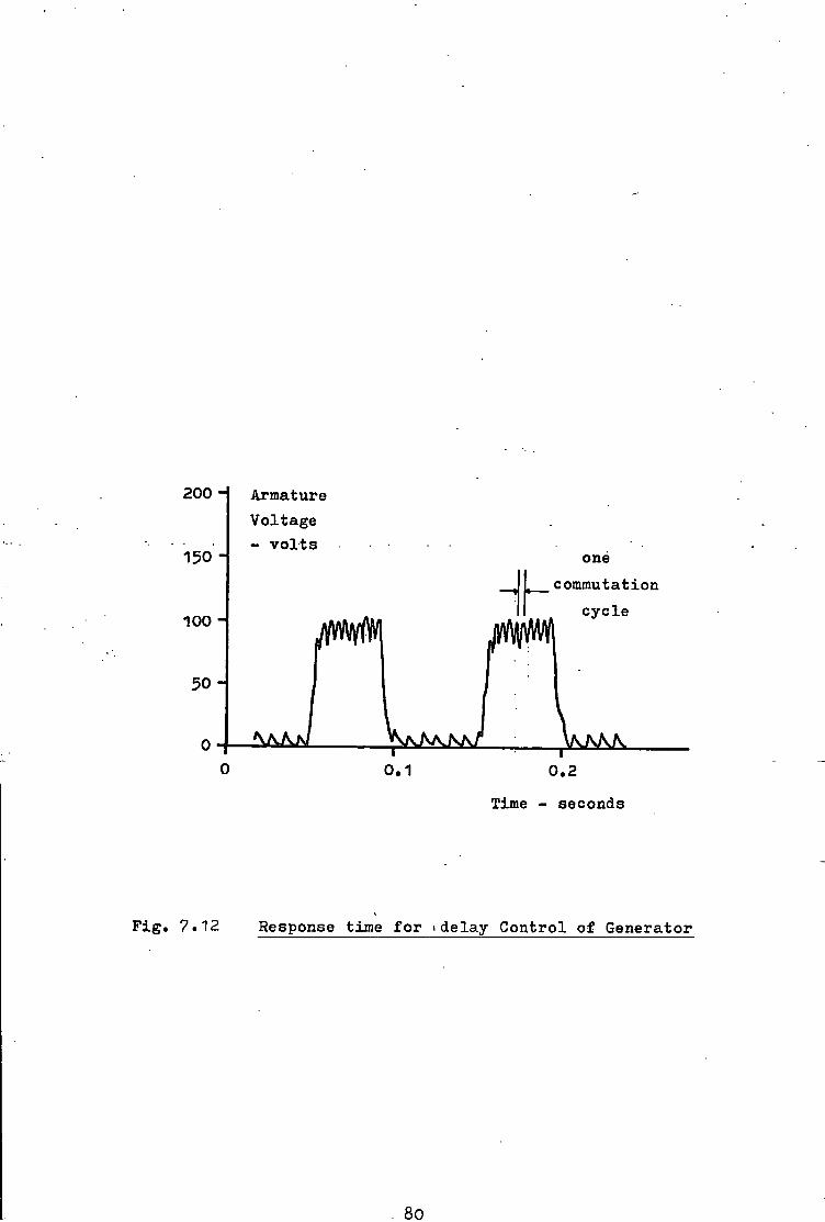
200 H
150 H
100 H
Armature Voltage - v o l t s
one commutatxon
0.1 0.2 Time - seconds
F i g . 7.12 Response time f o r > delay C o n t r o l of Generator
80

Chapter 8 The E x p e r i m e n t a l Machine
8.1 D e t a i l s o f the E x p e r i m e n t a l Machine
The e x p e r i m e n t a l machine c o n s i s t e d o f a s p e c i a l l y c o n s t r u c t e d
s t a t o r i n w h i c h a c o n v e n t i o n a l armature from a 2 hp d i r e c t c u r r e n t
motor was p l a c e d . The s t a t o r was l a m i n a t e d so t h a t any f l u x p u l s a t i o n s
c o u l d be measured and n o t be damped out by the f o r m a t i o n o f eddy
c u r r e n t s . Moveable f i e l d and commutating p o l e s completed t h e s t a t o r
i r o n c i r c u i t . E i g h t t a p p i n g s f r o m t h e o r i g i n a l motor commutator
were t a k e n t o a l t e r n a t e segments on a new two p a r t commutator f a s t e n e d
t o an e x t e n s i o n o f t h e s h a f t . A dynamometer was a l s o connected t o
the s h a f t so t h a t the e x p e r i m e n t a l machine c o u l d be t e s t e d under
motor or g e n e r a t o r c o n d i t i o n s . F i g u r e 8.1 shows the l a y o u t o f t h e
•machine and d e t a i l s o f t h e magnetic - c i r c u i t are • g i v e n i n Appendix C;
A schematic diagram o f the e l e c t r i c a l c o n n e c t i o n s between the
o r i g i n a l and new commutators i s shown i n F i g u r e 8 .2 . Since the
o r i g i n a l commutator had 57 b a r s , t h e r e were 7 b a r s between most
t a p p i n g s b u t e i g h t b a r s between two t a p p i n g s . The o u t p u t v o l t a g e o f
the t . a . c . g e n e r a t o r showed no d i s c e r n a b l e d i f f e r e n c e between the
t a p p i n g s space'd 7" or 8 bars a p a r t . "Figure 8.3 shows the o u t p u t v o l t a g e ,
t h e r i p p l e b e i n g due t o s l o t e f f e c t s .
8.2 The P a r t Commutators
Each p a r t commutator had e i g h t b r a s s segments around i t s
c i r c u m f e r e n c e and an a i r gap s e p a r a t e d each segment from i t s
n e i g h b o u r . Normal carbon brushes were arranged i n p a i r s such t h a t
a t no t i m e c o u l d t h e y b r i d g e more t h a n two segments. The brushes
were h e l d i n c o n v e n t i o n a l brush h o l d e r s and were r u n a t average
c u r r e n t d e n s i t i e s o f about one t h i r d o f t h e i r r a t e d v a l u e s .
81

a* (0
\ If) to OQ
\ m i
in
IU I
LlJ
I
I
CD
CO
0)
O i
82

I F i g . 8.2 E l e c t r i c a l Connection of Two part Commutator
Armature
Voltage 180 H
120
6o i
— r -10 20 30 *f0
"T" 50
F i g . 8.3
Time - m i l l i s e c o n d s
Voltage Waveform of T.A.C. Generator
83

At speeds g r e a t e r t h a n 1800 r e v / m i n i n t e r m i t t e n t s p a r k i n g was
observed under the brushes. E x t r a p r e s s u r e on a brush would h e l p t o
reduce the s p a r k i n g under t h a t b r u s h and a l s o under the o t h e r brush
o f t h e same p a i r . The l o n g e r t h e machine r a n , the worse the s p a r k i n g
became and m a r k i n g o f the commutator s u r f a c e was observed. The
waveforms o f t h e c u r r e n t s i n t h e b r u s h c i r c u i t were m o n i t o r e d and no
i r r e g u l a r i t y was n o t i c e d i n the c u r r e n t t o t h e b r u s h p a i r - F i g u r e
8.4 ( a ) . The waveforms f o r t h e l e a d i n g and t r a i l i n g brushes showed
some v e r y r a p i d t r a n s f e r s o f c u r r e n t - F i g u r e 8.4 ( b ) . When the
t r a i l i n g b r u s h j u s t makes c o n t a c t w i t h t h e segment t h e r e i s an
immediate c u r r e n t s h a r i n g . I n t h i s p o s i t i o n , the i n s t a n t a n e o u s
c u r r e n t d e n s i t y a l o n g the edge o f t h e b r u s h may be many t i m e s ( ? 2 0 )
g r e a t e r than i t s r a t e d v a l u e . A s i m i l a r s i t u a t i o n e x i s t s as t h e
l e a d i n g b r u s h ' i s j u s t about t o - l e a v e " t h e segment.
To e l i m i n a t e t h i s t r a n s f e r , a d i f f e r e n t d e s i g n o f commutator ( 8 1 )
l a y o u t was used " and the b r u s h p a i r r e p l a c e d by a s i n g l e b r u s h .
F i g u r e 8.5 shows the schematic l a y o u t o f t h e m o d i f i e d p a r t commutator.
Subsequent r u n n i n g o f the e x p e r i m e n t a l machine showed no apparent
commutator s u r f a c e damage and no under b r u s h s p a r k i n g . F u r t h e r l o n g
d u r a t i o n t e s t s are r e q u i r e d b e f o r e any f i r m c o n c l u s i o n s about the r e l a t i v e m e r i t s o f t h e two commutator d e s i g n s may be made. Recent
(8 2 8 3)
t e s t s by Bates * 1 " have shown t h a t carbon f i b r e p r o t e c t i n g
brushes can be e x t r e m e l y h e l p f u l i n r e d u c i n g s u r f a c e damage. Such
brushes may be necessary on l a r g e machines w i t h t h e i r h i g h e r c u r r e n t
r a t i n g s b u t , f o r s m a l l machines, the m o d i f i e d commutator may be
s u f f i c i e n t t o p r e v e n t marking and s p a r k i n g by e l i m i n a t i n g the r a p i d
c u r r e n t t r a n s f e r s .
84

10A
\ / ( a ) T o t a l brush c u r r e n t
Time m i l l i s e c o n d s 10A
(b) l e a d i n g brush c u r r e n t
10A \ (b) t r a i l i n g brush c u r r e n t
F i g . 8.k Brush Current Waveforms
^ OOOOflCO, e
A F i g . 8.5 Modified Part Commutator
85

8.3 Brush P o s i t i o n s and Commutation Angles
I n a c o n v e n t i o n a l machine commutation t a k e s p l a c e i n S ,
b e g i n n i n g a t b e f o r e t h e n e u t r a l a x i s and f i n i s h i n g a t a f t e r .
The mean a r m a t u r e a x i s p o s i t i o n t h u s l i e s a l o n g t h e n e u t r a l a x i s .
By a n a l o g y , t h e commutation process i n the t . a . c . machine i s a r r a n g e d
t o commence a t -2-(s-2b)° b e f o r e t h e n e u t r a l a x i s so t h a t i f commutation
takes a l l t h e a v a i l a b l e a n g l e , t h e mean a x i s p o s i t i o n i s s t i l l a l o n g
the n e u t r a l a x i s . The maximum a n g l e over which commutation can
take p l a c e i s t h e segment angle l e s s t w i c e the b r u s h arc
I f commutation i s completed i n a s m a l l e r angle the e f f e c t w i l l be t o
move t h e mean p o s i t i o n away from t h e n e u t r a l a x i s by some a n g l e 6.
T h i s new p o s i t i o n w i l l be i n f r o n t o f t h e n e u t r a l a x i s i n t h e d i r e c t i o n
of r o t a t i o n and so © i s d e f i n e d t o have a n e g a t i v e v a l u e . T h i s value
w i l l i n c r e a s e i n magnitude as t h e process o f commutation becomes
q u i c k e r f o r any g i v e n speed. I t can be shown t h a t the average a r m a t u r e
a x i s p o s i t i o n i s i d e n t i c a l f o r b o t h commutator and s l i p r i n g modes
o f o p e r a t i o n and t h a t the va l u e o f 0 w i l l l i e between -g-(s-2b)° and
0° f o r s p a r k l e s s commutation w i t h no t h y r i s t o r f i r i n g d e l a y .
For t h e e x p e r i m e n t a l machine the segment arc was 45° and t h e
br u s h a rc 7^°] the maximum commutation a n g l e was 32°. Commutation
was ar r a n g e d t o s t a r t 16° b e f o r e the n e u t r a l a x i s i n t h e d i r e c t i o n
o f r o t a t i o n . The motor was p a r t i c u l a r l y s e n s i t i v e t o s m a l l changes
o f a n g le and t o o b t a i n s i m i l a r c h a r a c t e r i s t i c s f o r r e v e r s i b l e
r u n n i n g , t h e s t a r t i n g a n g le o f the commutation process must be
a c c u r a t e l y s e t .
8 .k The T r i g g e r i n g C i r c u i t s
To f i r e t h e t h y r i s t o r s a t the c o r r e c t t i m e , a means o f
s y n c h r o n i s i n g t h e t r i g g e r i n g c i r c u i t w i t h the speed and p o s i t i o n o f
86

t h e s h a f t was r e q u i r e d . A simple way was t o gate t h e t r i g g e r i n g
c i r c u i t by u s i n g a c o n t a c t made w i t h a c o n d u c t i n g s u r f a c e i n an e x t r a
r i n g which r o t a t e s w i t h t h e s h a f t . The need f o r r e l i a b l e t r i g g e r i n g
i s emphasised. I f a t h y r i s t o r f a i l s t o t r i g g e r i n t o c o n d u c t i o n e i t h e r
t h r o u g h a f a u l t i n t h e . t r i g g e r c i r c u i t , bad c o n t a c t w i t h the
s y n c h r o n i s i n g r i n g or by the f a i l u r e o f a t h y r i s t o r i t s e l f , t h e n
s p a r k l e s s commutation w i l l n ot o c c u r . As the b r u s h l e a v e s an a c t i v e
segment a s p a r k w i l l be drawn from the t r a i l i n g b r u s h edge back t o
the segment. Commutation may s t i l l occur as the b r u s h e s t a b l i s h e s
i t s e l f on t h e n e x t segment and the r e v e r s a l o f t h e c u r r e n t done
p u r e l y by r e s i s t a n c e commutation. The arc w i l l e x t i n g u i s h o n l y t o
reappear a t t h e end o f t h e next segment. A more l i k e l y p o s s i b i l i t y
i s t h a t o f f l a s h o v e r where the arc does not e x t i n g u i s h b u t i s drawn
u n t i l i " t r e a c h e s the brushes o f the o p p o s i t e p o l a r i t y . . The f a i l u r e
o f a t h y r i s t o r t o conduct, from whatever cause, w i l l l e a d t o severe
s p a r k i n g and commutator damage.
The r e q u i r e m e n t s o f t h e t r i g g e r c i r c u i t are two f o l d : i t must
p r o v i d e an o u t p u t s i g n a l s u f f i c i e n t t o i n i t i a t e c o n d u c t i o n and i t
must do so a t a time d e t e r m i n e d by t h e s y n c h r o n i s i n g r i n g . I n g e n e r a l ,
a t h y r i s t o r w i l l be t r i g g e r e d by a v o l t a g e o f +3 t o +10 v o l t s b e i n g
a p p l i e d t o t h e g a t e . T h i s v o l t a g e may be e i t h e r a d.c. l e v e l o r i t
may be i n t h e form o f p u l s e s - the minimum p u l s e w i d t h b e i n g d e t e r
mined by t h e t i m e c o n s t a n t o f the c i r c u i t . F i g u r e 8.6 shows the
o s c i l l a t o r y waveform o f t h e s e r i e s i n t e r p o l e motor w i t h d i f f e r e n t
f i r i n g p u l s e w i d t h s . W i t h a narrow p u l s e , the t h y r i s t o r s need t o be
more f o r w a r d b i a s e d b e f o r e the c u r r e n t can reach l a t c h i n g v a l u e (
about 30 mA) b e f o r e the p u l s e i s removed. F u r t h e r i n f o r m a t i o n on
t r i g g e r i n g c i r c u i t s may be found i n References 8.5 and 8 .6.
8?

Armature c u r r e n t - Amperes 1*f
100 uS 25 uS 12 pulse pulse
10
8 •
i
• I
8 10 12 14 16 18 20 22 Time - seconds
F i g . 8.6 Motor C u r r e n t Response - Pulse w i d t h v a r i a t i o n
88

8.5 The E l e c t r o n i c and E l e c t r i c a l C i r c u i t s
The f i r s t t r i g g e r c i r c u i t used a f r e e r u n n i n g , 5 kHz square wave
o s c i l l a t o r w h i c h produced two a n t i - p h a s e o u t p u t s . These were f e d t o
b l o c k i n g a m p l i f i e r s which o n l y t r a n s m i t t e d and a m p l i f i e d t h e s i g n a l s
when a c o n t a c t was made on t h e s y n c h r o n i s i n g r i n g . The a m p l i f i e r
o u t p u t s were t r a n s f o r m e d down to produce i s o l a t e d +k v o l t p u l s e s .
The e l e c t r o n i c c i r c u i t i s g i v e n i n F i g u r e 8.7.
The second t r i g g e r c i r c u i t i n c o r p o r a t e d a d e l a y u n i t which delayed
t h e f i r i n g p u l s e s f o r a v a r i a b l e time a f t e r i n i t i a l c o n t a c t had been
made w i t h t h e s y n c h r o n i s i n g r i n g . The t i m e delay c o u l d be a d j u s t e d
m a n u a l l y or ' a u t o m a t i c a l l y ' by an e x t e r n a l a.c. or d.c. s i g n a l . The
b l o c k diagram and c i r c u i t d e t a i l s are g i v e n i n F i g u r e 8.8 and t h e
l i n e a r i t y .of t h e d e l a y t i m e t o the e x t e r n a l . s i g n a l i n Figure. 8.9.
The l i n e a r i t y was w i t h i n 1% over an i n p u t range o f -10 v o l t s . Appendix
C l i s t s t he d e l a y times' f o r t h e d i f f e r e n t manual s e t t i n g s o f the
c o n t r o l u n i t .
The t . a . c . machine c o u l d be used e i t h e r as a motor o r as a
g e n e r a t o r : t h e o u t p u t o f t h e g e n e r a t o r b e i n g d i s s i p a t e d as heat i n
a r e s i s t o r bank. I n the former- case, the armature was -su-pp-l-i-ed w i t h
200 v o l t s f r o m a d i r e c t c u r r e n t source. A unique p r o p e r t y o f t h e
t . a . c . machine i s t h a t a s e r i e s or a s e p a r a t e l y e x c i t e d i n t e r p o l e
may be used t o induce the commutation v o l t a g e . A v a r i a b l e r e s i s t o r
was used t o a d j u s t the v a l u e o f the s e p a r a t e e x c i t a t i o n c u r r e n t b u t
i t was g e n e r a l l y s e t t o 10 amperes. A c i r c u i t diagram showing t h e
v a r i o u s s w i t c h e s , meters, r e s i s t o r s and c o n n e c t i o n s i s g i v e n i n
F i g u r e 8.10.
89

in CN
l.i "••WW—'
CD
•
i —WW—«
i n l -
0C7 —WW—• B>'HII «rwi
i -0.E5-
>' CO
I
f
> o
n _ r '
032
1*700 LW-0
I I -
L-VWA--WW M0Z3
L 7
u 9
i A/VW~" >U3
1 001
1 001
< O
O
sr 00 u o~ I/) o .52 '55 -•c n»
90
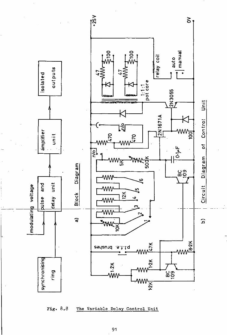
CD
O >
C '•«-< iS 3 o e
1_ &
• — °. . c
mp
y
gram
"D b C E rd di >. (J W rfl o •3 0/ m O
-JWWc1-t-AAW
(4
> i n +
> o
o o o o
4Ck -Kh
O o >» <L>
o i o j E
J L O u o a
-<ni»»H69iwuw»«ni umK'-
in in O m z
o o c-«.
z CM
1 -WW in o in
•AA/W i o
Li_
o
(_) CT) CQ O Yin
CSI
HWW-
•A/W\A
U CD m o
c 3
C o u
E fltf l _
at
3 u
F i g . 8.8 The V a r i a b l e Delay C o n t r o l U n i t
91

Time Delay - m i l l i s e c o n d s M
Modulating Voltage i
20 10 10 20 v o l t s I I
l i m i t of l i n e a r i t y
F i g . 8.9 L i n e a r i t y of V a r i a b l e Time Delay Con t r o l Unit
92

P|3!J
dlOCfjd^U]
93

7 Chapter y5 C o n c l u s i o n s and Recommendations
JjQrf Comments and Recommendations
The e x p e r i m e n t a l machine r a n f o r some 1500 hours w i t h o u t
f a i l u r e o f any e l e c t r i c a l o r e l e c t r o n i c p a r t . The s p a r k i n g and
ma r k i n g on the o r i g i n a l commutator was absent from the m o d i f i e d
commutator but t h e performance o f the machine was unchanged by the
m o d i f i c a t i o n . The machine proved capable o f w i t h s t a n d i n g o v e r l o a d s
o f up t o f o u r t i m e s t h e r a t e d c u r r e n t w i t h o u t s p a r k i n g .
One o f t h e advantages o f t h e g e n e r a l t h e o r y i s t h a t the
measurements o f i n d u c t a n c e may be made under s t a n d s t i l l c o n d i t i o n s .
The s t u d y has c o n f i r m e d t h i s - b u t o n l y i f the e x c i t i n g c u r r e n t s used
i n t h e measurements were o f t h e same o r d e r as the normal o p e r a t i n g
c u r r e n t s . M i s l e a d i n g r e s u l t s a r e o b t a i n e d i f v e r y s m a l l e x c i t i n g
c u r r e n t s are used t o mi n i m i s e h e a t i n g e f f e c t s , e t c . I t i s s t r o n g l y
recommended t h a t any s t a n d s t i l l r e s u l t s , p a r t i c u l a r l y o f i n d u c t a n c e ,
are c o n f i r m e d i f p o s s i b l e by t e s t s made on the machine under normal
o p e r a t i n g c o n d i t i o n s . For example, the open c i r c u i t t e s t o f the
g e n e r a t o r can be used t o check t h e v a l u e o f M„ . The measurements f a
must be a c c u r a t e because s m a l l changes or e r r o r s can s e r i o u s l y , a f f e c t
t h e v a l i d i t y o f the computed r e s u l t s . S a t u r a t i o n i n t h e d i r e c t and
q u a d r a t u r e axes must a l s o be c a r e f u l l y measured. T h i s recommendation
i s made a f t e r p e r s o n a l e x p e r i e n c e o f t h e need f o r c a r e f u l measurement
u s i n g c u r r e n t s t h r o u g h o u t the c u r r e n t range o f the w i n d i n g s . T h i s
i s e s s e n t i a l i f s a t u r a t i o n e f f e c t s are t o be i n c l u d e d . A l t h o u g h
t e d i o u s , t i m e spent i n measuring the i n d u c t a n c e c o e f f i c i e n t s
a c c u r a t e l y w i l l be r e p a i d i n the q u a l i t y o f the r e s u l t s .

A v a l i d comment on t h e programme i s t h a t the i n d u c t a n c e wave
forms were t a k e n as e i t h e r s i n e or c o s i n e c u r v e s . T h i s has been
shown t o produce good r e s u l t s b u t b e t t e r a ccuracy may be o b t a i n e d
i f the a c t u a l waveforms are i n c o r p o r a t e d i n t o the programme. The
computer can be programmed t o c a l c u l a t e t h e v a l u e s o f the i n d u c t a n c e
and i t s s l o p e a t any d e s i r e d a n g l e .
lOrS' C o n c l u s i o n s
The o u t p u t o f a machine may be c o n t r o l l e d over a l i m i t e d range
by a method o f e l e c t r o n i c a l l y r o c k i n g t h e brushes by u s i n g delayed
t h y r i s t o r f i r i n g . S u f f i c i e n t e x p e r i m e n t a l r e s u l t s have been p r e s e n t e
t o show the n a t u r e o f the method and some o f the l i m i t a t i o n s imposed
by l o a d i n g e f f e c t s .
The m a t c h i n g o f the p r e d i c t e d and e x p e r i m e n t a l c h a r a c t e r i s t i c s
c o n f i r m the v a l i d i t y o f the method o f a n a l y s i s which was based upon
the g e n e r a l machine t h e o r y . The f a c t t h a t the t . a . c . machine
d i f f e r e d f r o m c o n v e n t i o n a l machines i n h a v i n g a l a r g e commutation
a n g l e , two zones o f o p e r a t i o n (commutator and s l i p r i n g ) and the
i n c l u s i o n o f t h y r i s t o r s i n the armature c i r c u i t can a l l be accounted
f o r i n the a n a l y s i s . The d i f f e r e n t i a l e q u a t i o n gave an a p p r o x i m a t e
i n d i c a t i o n o f the performance and a more a c c u r a t e p r e d i c t i o n was
o b t a i n e d w i t h the use o f a computer programme. P r o v i d i n g s u i t a b l e
n u m e r i c a l v a l u e s f o r the parameters were o b t a i n e d from the measure
ments, the computer s i m u l a t i o n c o u l d produce r e s u l t s which matched
those o b t a i n e d e x p e r i m e n t a l l y t o w i t h i n 5% o f t h e c u r r e n t and v o l t a g e
magnitudes, 5% o f t h e f r e q u e n c y o f t h e o s c i l l a t i o n s and 3% o f t h e
machine speed.
95"

The d i r e c t c u r r e n t machine w i t h t h y r i s t o r a s s i s t e d commutation
may be a n a l y s e d by t h e g e n e r a l t h e o r y . I t i s e s s e n t i a l t h a t the
d i f f e r e n c e s between the t . a . c . and c o n v e n t i o n a l machines are k e p t
i n mind and a l l o w a n c e made f o r them. The most i m p o r t a n t o f these
f a c t o r s i s t h a t o f the armature a x i s not b e i n g r e s t r i c t e d t o l i e
about t h e n e u t r a l a x i s . I t may be v a r i a b l e w i t h i n the range -20°
i n s t e a d o f -2°. T h i s i n t r o d u c e s terms i n t o t h e e q u a t i o n s t h a t would
n o r m a l l y be c o n s i d e r e d zero o r n e g l i g i b l e i n s t a n d a r d d.c. machines.
The two zones o f o p e r a t i o n c o m p l i c a t e the a n a l y s i s i n t h a t two s e t s
o f e q u a t i o n s must be m a n i p u l a t e d and combined a c c o r d i n g t o t h e
r e l a t i v e t imes o f each p e r i o d . The i n c l u s i o n o f the t h y r i s t o r s
l i m i t s the armature c u r r e n t t o zero and p o s i t i v e v a l u e s o n l y .
The work has p r o v i d e d a s a t i s f a c t o r y method o f a n a l y s i n g the
performance o f t'.a.c. machines. A computer programme based upon the
a n a l y s i s was developed and t h i s may be used t o p r e d i c t t h e c h a r a c t
e r i s t i c s o f the machine f o r d e s i g n changes which may be s t u d i e d i n
f u t u r e developments o f d i r e c t c u r r e n t machines w i t h t h y r i s t o r a s s i s t e d
commutation.
ysh ?6

9-3 F u r t h e r Work
The g e n e r a l machine t h e o r y has been shown to be a b l e to p r e d i c t a c c u r a t e l y the performance of the t.a. . c . machine. By u s i n g a v e r a g e v a l u e s the s t e a d y s t a t e c h a r a c t e r i s t i c s may be o b t a i n e d and a l s o i t s b e h a v i o u r under t r a n s i e n t c o n d i t i o n s . I t i s an e a s y s t e p to s i m p l i f y the dynamic e q u a t i o n s to o b t a i n the s t e a d y s t a t e c o n d i t i o n s but i t i s d i f f i c u l t t o o b t a i n dynamic r e s p o n s e s from e s s e n t i a l l y s t e a d y s t a t e e q u a t i o n s . T h i s i s a. j u s t i f i c a t i o n f o r the use of the g e n e r a l t h e o r y . The method does however, r e q u i r e the knowledge of c e r t a i n i n d u c t a n c e p a r a m e t e r s and, to prove the method the i n d u c t a n c e s were measured on an e x p e r i m e n t a l machine. The v a l u e s may be c a l c u l a t e d by c o n s i d e r i n g the f l u x ($>) produced by a c u r r e n t ( i ) i n a ( n ) t u r n w i n d i n g . S i n c e i n d u c t a n c e ( L ) i s g i v e n by
L = n. j> / i
an e s t i m a t e of t h e i n d u c t a n c e may be o b t a i n e d . Problems do e x i s t i n
the c a l c u l a t i o n s and, i n p a r t i c u l a r , the e f f e c t s of s a t u r a t i o n a r e
complex.
A s t u d y i n t o the c a l c u l a t i o n of t h e s e i n d u c t a n c e s from the d e s i g n
d a t a , i . e . the e l e c t r i c a l and m e c h a n i c a l d e t a i l s , would e n a b l e the
b e h a v i o u r of t . a . c . machines t o be c a l c u l a t e d a t the d e s i g n s t a g e .
97
Appendices
>©5 93

Appendix A The Measurement o f I n d u c t a n c e
A.1 The D.C. In d u c t a n c e B r i d g e
The b r i d g e used t o measure the v a r i a t i o n o f the i n d u c t a n c e
c o e f f i c i e n t s i s based upon t h a t d e s c r i b e d by P r e s c o t t and E l - K a r a s h i .
Jones compares h i s i n d u c t a n c e b r i d g e which uses a b a l l i s t i c g a l v a n -(A. 1 )
ometer * w i t h t h a t o f P r e s c o t t ' s i n which a f l u x m e t e r i s used as
the d e t e c t i n g i n s t r u m e n t . He concludes t h a t , a l t h o u g h the g a l v a n
ometer i s more s e n s i t i v e , r e a d i n g s must be t a k e n i n a t i m e which i s
s m a l l compared t o t h e t i m e r e q u i r e d f o r a q u a r t e r swing o f the
galvanometer. The f l u x m e t e r would r e c o r d even minute changes o f (A.2)
v o l t a g e q u i t e f a i t h f u l l y . More r e c e n t l y , B a r t o n and D u n f i e l d
have used o p e r a t i o n a l a m p l i f i e r s as the d e t e c t o r .
The b a s i c c i r c u i t i s shown i n F i g u r e A.1 and c o n s i s t s i d e a l l y
o f a c o n s t a n t c u r r e n t s o u r c e , a s w i t c h , a non i n d u c t i v e r e s i s t o r ,
a non r e s i s t i v e i n d u c t o r and a v o l t a g e i n t e g r a t o r . I n i t i a l l y the
s w i t c h i s c l o s e d and t h e c u r r e n t ( I ) f l o w s t h r o u g h i t . The s w i t c h
i s t h e n opened and the c u r r e n t r e d i s t r i b u t e s i t s e l f i n t o a c u r r e n t
( i ^ ) t h r o u g h t h e r e s i s t o r and c u r r e n t (±^) t h r o u g h t h e i n d u c t o r .
The v o l t a g e a c r o s s t h e i n t e g r a t o r i s v = L . d ( i 2 ) / d t = R . i 1
and, s i n c e I = i + i
R.I R . i 2 + L . d ( i ) / d t
The s o l u t i o n o f t h i s e q u a t i o n i s
= I . ( l - e - ( R / L ) . t ) 2 The v o l t a g e a c r o s s the i n t e g r a t o r i s t h e r e f o r e
v = L . d ( i 2 ) / d t = R.I.e - ( R / L ) . t

\ s R
F i g . A.1 B a s i c C i r c u i t f o r Inductance Measurement
R e r 3AAAAAr j . (' ;
—vAAAAA/—^mssifSr—L
R L R,
l i f
Ri
SAAAAAr-
F i g . A.2 The D i r e c t C u r r e n t Inductance Bridge
loo

and the i n t e g r a l o f t h i s v o l t a g e w i t h r e s p e c t t o time i s »
v. Ab = L - I o
The v o l t a g e i n t e g r a t o r reads i> and the i n d u c t a n c e i s g i v e n by
L = «F/ I
P r a c t i c a l l y , an i n d u c t o r w i l l have r e s i s t a n c e and the v o l t a g e
a c r o s s the i n t e g r a t o r w i l l n ot be zero b u t w i l l be r . i where r i s
the r e s i s t a n c e o f t h e i n d u c t o r and i t h e c u r r e n t t h r o u g h i t . S ince
the f l u x m e t e r i n t e g r a t e s the v o l t a g e a c r o s s i t s t e r m i n a l s t h e r e w i l l
be no steady s t a t e r e s u l t . To overcome these d i f f i c u l t i e s t h e i n d u c t a n c e
b r i d g e i s used t o compensate f o r t h e r e s i s t a n c e o f the c o i l .
A.2 C a l i b r a t i o n and Use o f B r i d g e
The c i r c u i t o f the b r i d g e . ' i s g i v e n i n F i g u r e A.2.- R e s i s t o r s
and R^ are e q u a l i n v a l u e and s m a l l compared t o the f l u x m e t e r
r e s i s t a n c e . R e s i s t a n c e R^ i s v a r i a b l e so t h a t i t c o u l d be s e t e q u a l
t o the r e s i s t a n c e o f t h e c o i l under t e s t . R e s i s t o r R^ s e t s t h e
magnitude o f the e x c i t i n g c u r r e n t .
To c a l i b r a t e , a r e s i s t a n c e R g e q u i v a l e n t i n value t o t h a t o f t h e
c o i l was s u b s t i t u t e d f o r t h e c o i l . The r e s i s t o r R^, w a s a d j u s t e d t o
balance the b r i d g e . S w i t c h e s and S^ were opened and a known
v o l t a g e p l a c e d a c r o s s s w i t c h S^ f o r a known time t seconds. The
d e f l e c t i o n o f t h e f l u x m e t e r (*J0 was r e c o r d e d . The c o n s t a n t o f
p r o p o r t i o n a l i t y (K) i s g i v e n by
K = E 2 . t / Y
and has the u n i t s o f v o l t - s e c o n d s per weber t u r n .
Since i n d u c t a n c e i s d e f i n e d as v o l t - s e c o n d s per ampere, i t i s
o n l y necessary t o note the f l u x m e t e r d e f l e c t i o n Cf*) f o r a change o f
ya8 101

c u r r e n t ( i ) . The i n d u c t a n c e i s , t h e r e f o r e
L = K . f / i Henry
A s i m p l e m o d i f i c a t i o n a l l o w s the m u t u a l i n d u c t a n c e between two
c o i l s t o be measured - F i g u r e A.3« By a n a l o g y w i t h the s e l f
i n d u c t a n c e c i r c u i t , the m u t u a l i n d u c t a n c e i s
M 2 ^ = K. <p/ i n Henry
T h i s c i r c u i t may a l s o be used t o measure t h e v a l u e s a t d i f f e r e n t
l e v e l s o f s a t u r a t i o n by a d j u s t i n g the v a l u e o f the c u r r e n t ( i , , ) .
A.3 P r a c t i c a l D i f f i c u l t i e s w i t h t h e 3 r i d g e
W i t h s m a l l c u r r e n t s ( l e s s t h a n 0.01 A) the h e a t i n g e f f e c t o f t h e
c u r r e n t was n e g l i g i b l e and the b r i d g e c o u l d be q u i c k l y b a l a n c e d . At
h i g h e r c u r r e n t l e v e l s the b r i d g e t o o k a c o n s i d e r a b l e t i m e t o r e a c h
e q u i l i b r i u m and the .only a c c u r a t e way o f o b t a i n i n g r e s u l t s was by
s w i t c h i n g o f f the c u r r e n t . An e s t i m a t e o f h y s t e r i s e f f e c t s was done
by t a k i n g the average o f two r e a d i n g s ; one as the c u r r e n t changed
from +1 t o 0, t h e second as t h e c u r r e n t changed from - I t o 0. The
average o f these r e a d i n g s was used as the v a l u e o f the i n d u c t a n c e .
To enable h i g h e r c u r r e n t s t o f l o w , i t was necessary t o shunt
t h e f l u x m e t e r w i t h e x t e r n a l r e s i s t o r s . F i g u r e A.^ shows the
arrangement. The v a l u e o f the shunt r e s i s t o r R^ was 1 ohm w h i l e
t h a t o f R was a d j u s t e d t o g i v e as l a r g e a d e f l e c t i o n as p o s s i b l e . 5
C a l i b r a t i o n was necessary each time R was a d j u s t e d . By s e t t i n g R s s
t o a l a r g e v a l u e , any imbalance o f the b r i d g e does not cause the
f l u x m e t e r t o d e f l e c t w i l d l y . As t h e balance p o i n t i s approached the
v a l u e o f R s can be reduced t o the r e q u i r e d v a l u e .
The i n t r o d u c t i o n o f ammeters can s e r i o u s l y a f f e c t t h e v a l i d i t y
o f the r e s u l t s . Some i n s t r u m e n t s , i n p a r t i c u l a r microammeters, had

E 6
c o i l C i
—\/WWV—ouaftMSLr R C O i l C;
R?
1 I t i Ep R5 S?
A P . ^.R^
R-
F i g . A.3 Mutual Inductance Bridge
R
R, R
F i g . A.^ The Shunted Fluxraeter
yr6 /03

a l a r g e i n d u c t a n c e w h i c h c o u l d be many t i m e s t h a t o f the c o i l under
t e s t . By u s i n g two ammeters o f t h e same r a t i n g , one i n each arm o f
the b r i d g e , the o v e r a l l e f f e c t o f t h e meters c o u l d be made s m a l l .
D u r i n g the c a l i b r a t i o n checks,, the o n l y i n d u c t a n c e i n t h e c i r c u i t
i s t h a t o f the meters and t h e i r e f f e c t s can be c a l c u l a t e d . C o r r e c t i o n s
were made t o the i n d u c t a n c e c o e f f i c i e n t s o n l y i f the meter c o n t r i b u t i o n
was more th a n 1-2% o f t h e f l u x m e t e r r e a d i n g .
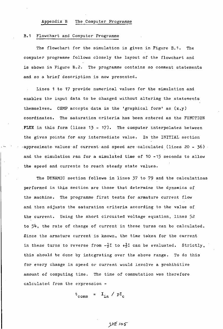
Appendix B The Computer Programme
B .1 Flowchart and Computer Programme
The flowchart f o r the s i m u l a t i o n i s given i n Figure B . 1 . The
computer programme follows c l o s e l y the layout of the flowchart and
i s shown i n Figure B . 2 . The programme contains no comment statements
and so a b r i e f d e s c r i p t i o n i s now presented.
L i n e s 1 to 17 provide numerical values f o r the s i m u l a t i o n and
enables the input data to be changed without a l t e r i n g the statements
themselves. CSMP accepts data i n the 'gra p h i c a l form' as (x,y)
c o o r d i n a t e s . The s a t u r a t i o n c r i t e r i a has been entered as the FUNCTION
FLUX i n t h i s form ( l i n e s 15 - 1 7 ) . The computer i n t e r p o l a t e s between
the given points for any intermediate value. I n the INITIAL s e c t i o n
approximate values - of current•and- speed are c a l c u l a t e d ( l i n e s 20 - >6)
and the si m u l a t i o n ran fo r a simulated time of 10 - 1 5 seconds to allow
the speed and c u r r e n t s to reach steady s t a t e v a l u e s .
The DYNAMIC s e c t i o n f o l l o w s i n l i n e s 37 to 79 and the c a l c u l a t i o n s
performed i n t h i s s e c t i o n are those that determine the dynamics of
the machine. The programme f i r s t t e s t s for armature c u r r e n t flow
and then a d j u s t s the s a t u r a t i o n c r i t e r i a according to the value of
the c u r r e n t . Using the short c i r c u i t e d voltage equation, l i n e s 52
to 5^> the ra t e of change of c u r r e n t i n these turns can be c a l c u l a t e d .
Since the armature c u r r e n t i s known, the time taken for the curren t
i n these turns to r e v e r s e from --g-I to can be evaluated. S t r i c t l y ,
t h i s should be done by i n t e g r a t i n g over the above range. To do t h i s
for every change i n speed or c u r r e n t would i n v o l v e a p r o h i b i t i v e
amount of computing time. The time of commutation was th e r e f o r e
c a l c u l a t e d from the expre s s i o n -
t comm = I . / P i xa r c
yx£ /of

T h i s e x p r e s s i o n assumes that the i n i t i a l r a t e of i n c r e a s e i s
maintained and t h i s i s p r a c t i c a l l y true for speeds around the normal
operating v a l u e s . At s t a r t i n g and slow speeds t h i s method gives
o p t i m i s t i c values for the time of commutation. Above 200 rev/min
there i s l e s s than h% e r r o r between the i n t e g r a t i o n method and the
method using the i n i t i a l r a t e of i n c r e a s e . Around the normal operating
value of 2000 rev/min, the e r r o r i s l e s s than 1%.
The r e l a t i v e times of the commutation period and the s l i p r i n g
period allow the average value of to be c a l c u l a t e d ( l i n e s 5 7 , 6 2 , 6 3 ) .
The r a t e s of change of c u r r e n t and speed are then computed for each
period and combined according to the r e l a t i v e times of each period,
l i n e s 6k to 76 r e f e r . The dynamic s e c t i o n i s then repeated u n t i l
the s i m u l a t i o n time i s equal to that s p e c i f i e d on the TIMER card,
( l i n e 8 8 ) . A f t e r each run through the dynamic s e c t i o n the r a t e s of
change of current and speed are fed i n t o an i n t e g r a t i o n r o u t i n e . New
values are computed from the old values and the r a t e s of change and
the new values are fed back i n t o the dynamic s e c t i o n . By t h i s process
the performance of the machine can be determined.
B . 2 I n t r o d u c t i o n of Step Changes
The i n t r o d u c t i o n of a st e p change i s performed by a F o r t r a n I F
statement i n the DYNAMIC s e c t i o n . Up to a c e r t a i n s p e c i f i e d time,
the s i m u l a t i o n uses a p a r t i c u l a r value for one of the machine's
parameters. At and a f t e r t h i s time another value i s used. I n the
programme, the machine i s s i m u l a t i n g the e f f e c t of a change i n the
delay time of the f i r i n g p u l s e s . Up to 10 seconds, a time delay of
1.Mf mS i s used; at and a f t e r 10 seconds, the time delay i s O .36 mS.
Fur t h e r information on CSMP may be obtained from Reference B.I
and on F o r t r a n IV from Reference B . 2
Hi; BR.'
1*3 /06
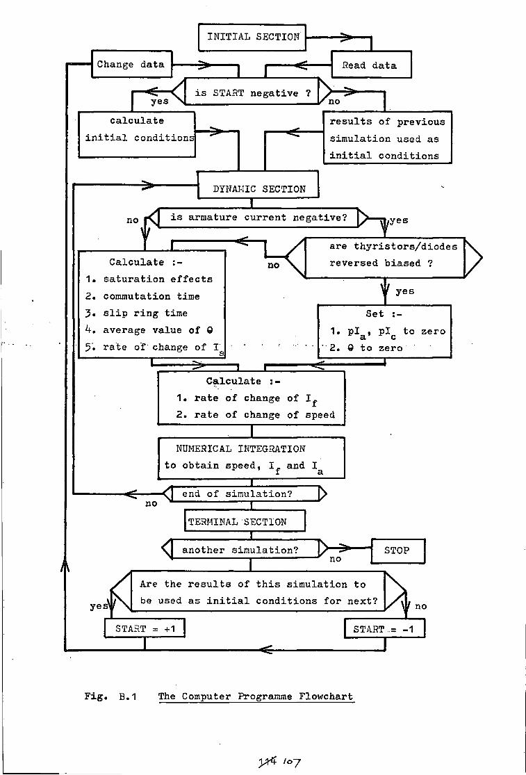
A
Change data
INITIAL SECTION
yes < i s START negative ?
Read data
c a l c u l a t e i n i t i a l condition:
r e s u l t s of previous s i m u l a t i o n used as i n i t i a l c o n d i t i o n s
DYNAMIC SECTION
no t I i s armature c u r r e n t negative?
C a l c u l a t e 1. s a t u r a t i o n e f f e c t s 2 . commutation time J . s l i p r i n g time k, average value of 0 5 . r a t e of change of I'
X
^no
/ > - ^ y e s
are t h y r i s t o r s / d i o d e s r e v e r s e d b i a s e d ?
I yes
Set :-1. p i , p i to zero
a c 2. 0 to zero
1 c C a l c u l a t e :-
1. r a t e of change of 2. r a t e of change of speed
NUMERICAL INTEGRATION to o b t ain speed, 1^ and I
f a
no ^ end of s i m u l a t i o n ?
— 1 —
TERMINAL SECTION X
yes 1
another s i m u l a t i o n ? I
STOP STOP no
Are the r e s u l t s of t h i s s i m u l a t i o n to be used as i n i t i a l c o n d i t i o n s for next?
START = +1
no
START.- -1 z z i —
F i g . B .1 The Computer Programme Flowchart
yr4 /07

* * * « * c u to 2
o «
in o in in I N m j I A
o c o c o * % % % x
o c c o e: N I O C J - o
t-H rn
•c QJ ^ 4J O V) •
•— O (A CM VI I <D
x I . O O • •U 00 W rH
— I . V. > % -C o I— . 10 1. rH O I
x E o <C • tO rH 0 I t_ Q- S.
O « • * CM * rH * I * « x « O * • * O * rH * I * » * * II * — * I * a.
o O • •
o o II II C_> O CC — I
o CP> rH O
• • o * N O • O II II rH II O U II o < < o —
U . Z OS —I 2L
o -3-
J - rH J - I • II
H U . m II > • CM O r- II
x " 3 O O
x • rH I O O x II w o o u r c II n h
II < II u rH — LI. < I — > LL
-r «r •sr *=r
% X l O t-H
X x rH
CM o in o I I ii n II < < CJ CJ
< < oc —i u_ —
2 2
o o in m o »D 10 N ^ in o s i n j m o o o o o
x x x x x
o o o o cn rH in en in
rH CM
o o o in o H H CM (O N 0 0 3 1D
r H O O O O x x x x x
O O O C O
O ^ C O M O rH CM
o o in in o ( O i c i c a i o
O CO 12 J - J rH O O O O X X X X X
O O C5 O O
I rH rH O O x x rH II • • rH rH O I X
O O • • « II Z3 o o in c o |— i co in n II n cc till II < < O <
U . LL U . - < h Z
t£ J 2 2 2 W O -r "sr "sr i —
o o rH
% O o
CM X * < u.
o < O > II II x x o o
• • CM O O rH
< < < < < < < < < < < o < < < < < < < < < < < I 3 * 0.0-0.0.0.0.0.0.0.0.0.11.
DC o to o
CM « • • • h - H U . 0 U J O LU O ii or OC LU 21 1 O 3 X o • >- < • • II " Z! rH CM II CM rH • o
- J i - LL LL. CM CM < rH — X X o X X X o II C {/) 1 - > X X r - II r - II II LU II 11 n II < II | | ^ s - . u 1 - Z < u. LU rH CM fn LL. — — u. T-H CM U - LL X < O — u. CL O — — 1 X X t- co o — — to — — — Q. o.
O rH o © rH i-H
H N r A j i f l U j r ^ M m o H N m j i n i o s w c n o H N W J i n a r N e o o i o H N r A d ' i r i i D
F i g u r e B . 2

Z or < o Z 00 >- o Q 2
• • • • < or • • — 0 • • • h - — t— »- « < w < * < 0 in — Z CO CO < • — * < * LL 0 * 00 <r — 0 * * < * — or <
C J *•—. C J —J 1 — 0 or < ^ 2: — 1 L L
1 U - L L \ i _ l LL i —« «—
< O —> \— * r - < '—. C L \— < C < L U u. * < CO U J CO X * —* CO + U J * r - 0 ' — < * 0 O . < * • O ^ < • co — 0 CM — — U J < rH * —
• t- < — X H ^ C J * CO CM 1 < — 0- 1- U J * < f—* to
0 or — . * X in L L < L L — •f— < -1 * 0- ~ z 1— • \— — — — » . in * < — 0 +" U J C -CO — \ * —. r - CO z- * •K * * 0- CM < U J * — C J L L i— 0 * - X CM r - X < CO — — O 0 < + U J r - L L * QL — —
1 >- X ^ < * * — r - r -< — in _ J r - Z + —• CO < <
1 to * > f — < * or or + 0 • 5: 0 Z CO L L * < r - C J 1 1 0
U . LL O L U n O — • — * U . U J < 0 0 • 01 LL • U J Q I I 1— 0 CO 0 — U J U J — • • 0 CM — o_ HC.U1 O * 00 * < •H U J X rH i-H I I
* rH « w CO L U - C H < L L O 0- h- "* ^ < en a O 0 * * CL L U CO ~" c — cn UJ CM LL in or CO < U J no 2 + L U * z U J + + — CM r H LU • O * c Or C rH + C LP. U J O-
O CL I-H < 1 O h- Q O 0 co -=r L L CO or co * c C J
00 csi co O — * O • CM or ^ * rH L L L L * 0 * C J CO C J < ^ cn x * CM — < <C J - U J in to • L L — < I - C J < L L — 0 CM 0 O N .— »-» L L N«r» J - o_ t~- r» m — * L L C J — L L — —— •
0 < CM X — < * O r - • in * * L L *> < 2 cr c 0 CM U L O CM I D * r - — I D CM 0 O U J L L cr + L L 1 + 0 * * •
0 CM rH —1 O L U 1— t H * C J • • _ i cr 1 + h- O 0 1-• O + L L X < J - J -
— 5 CM h- O CD 1 < O < < C J — 1 0 O < • 0 ^ * 1— CO rH O rH CD + Z L L — • r - — < y— h - • rH t H CM — U L 0 • Z — + • CM r - • — < L L > > rH U J > L L < < L L
1 f - U J > L L O I D 0 U J • Z O < • O X > + ^ X + or or L L
U J 11 r> I I O O • O I I 0 I I 0 0 — • I I t—x — I I O O — Q - I I + * r - O c Z > - Z < L L 1- a O • CM L L L L CO rH Q — CM I I 1- I I I I < * I I • 11 I I h-— —1 — — L L => O I I O 0 L L < * ^ O — II O O < LLl < I I I I C J — O CO rH J— O r - — O CO I I < I I — 0 0 I I I I c: O . — O — a - i | - u i o < — « < < C J
5. z — h - < — U 1- h h h U U J »—<• C H H I - w U U I L L U L — 1 CM — | L L —— X—4 u_ — 0 U - Z3 U . — — — < 0 =) < — 0. L L CJ < 0 < L L Z X — — — —. — U L — h- C J — O — — CL 00 0. — l - or ca or — < r - O- 0- Q. 0. a. 0
Ol CO O CM rH tr\ J - in 10 O C I O O O O O 0 0 CM CM CM CM CM CM CM CM CM
i ^ o o m o H N W j i i n i r i s o o o ) O H N ^ j ' i n i D S M C i o H N f ' i j , i / \ i o N o c c r i O H N m ^ i ^ ^ j - j j j j ^ j j j j L n i n i ^ i n i r i L n L n i ^ i n i r i u 3 W i o i a ^ u 3 ^ u ) ^ u D i ^ S N h .
Figure B . 2
1 ^ / o ?

< ~ t— < LU I — X UJ H X ^ I - Z Z 00 — * co t-* < (— CO < * * <
< — CO - Z h s * o * <..?.• < — o — — *
* < o < — + +
CJ
< < UL U -* «
« * < <
I I
LL. LL. (— I -
I I
II II O CO I — V-
S o
< or I o
+ CJ u_ I
d O-
Q t - t * u o — < e: OT CD
II Q U -~ZZ. L L O —
< 3 — o — v
s C J CM — O ^ — _l ^ K - I U OT H CD Z I Z II — o II LU
< LU — CL — CO
o Q
i-H U l II < L L U J
I L L O . CC CO < II II II I - H N K> CO X X X
— or s o CC CO LU O
to z o <
u. < — > o.
O I -• %.z m i— U J N O D :
— CJ I — v Z < UJ z u.
O I
s s . Q HU12 O - J < O O
• Z Q O < UJ II UJ
h - N C L —1 L L CO UJ L L Q — UJ
z x d X
H Ul O • UJ <
O C L S UJ II CO
LU Q en
— Q <
Q 00 c or H- LU UJ c X UJ Z — I —J Q- "3 H S — I — H Q O C UJ — or z i— z S h - O - I — I — LU CO LU UJ
J i n i O N C O O I O H N r O d ' l f l U N C O O I O r l C M W J ' L L M x i N i s s s w o o w M w e o o o o o w o o c J i o i a i o i O l O
o z UJ
F i g u r e B . 2
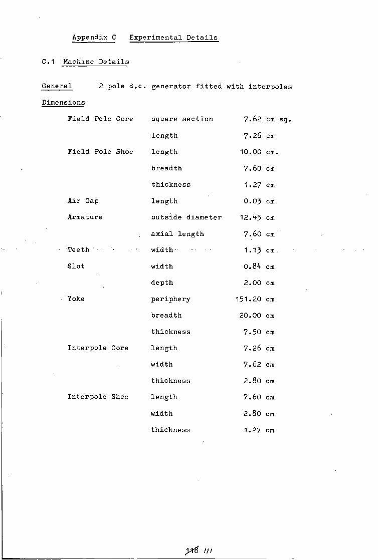
Appendix C Experimental D e t a i l s
C. 1 Machine D e t a i l s
General 2 pole d.c. generator f i t t e d with i n t e r p o l e s
Dimensions
F i e l d Pole Core square s e c t i o n 7 . 6 2 cm
length 7 . 2 6 cm
F i e l d Pole Shoe length 1 0 . 0 0 cm
breadth 7 . 6 0 cm
t h i c k n e s s 1 . 2 7 cm
A i r Gap lengt h 0 . 0 3 cm
Armature outside diameter 1 2 . ^ 5 cm
a x i a l length 7 . 6 0 cm
Teeth w i d t h " 1 . 1 3 cm
S l o t width 0.8k cm
depth 2 . 0 0 cm
Yoke periphery 1 5 1 . 2 0 cm
breadth 2 0 . 0 0 cm
t h i c k n e s s 7 . 5 0 cm
I n t e r p o l e Core length 7 . 2 6 cm
width 7 . 6 2 cm
t h i c k n e s s 2 . 8 0 cm
I n t e r p o l e Shce length 7 . 6 0 cm
width 2 . 8 0 cm
t h i c k n e s s 1 . 2 7 cm
y& in

C . 2 E l e c t r i c a l D e t a i l s
Rotor
Number of s l o t s 19
Conductors per s l o t 7 2
T o t a l conductors 1368
Commutator bars 57
F i e l d
Number of c o i l s 2
Turns per c o i l 8 3 3 3
Wire t h i c k n e s s 26 swg
Resistance 3 5 0 ohms
Current r a t i n g 0 . 3 ampere
I n t e r p o l e
Number of c o i l s 2
Turns per c o i l 3 0 0
Wire t h i c k n e s s 1*f swg
Resistance 0 . 5 ohms
Current r a t i n g 10 ampere
T h y r i s t o r s
Type BTY 99
Rating 70 ampere
yti 1/2
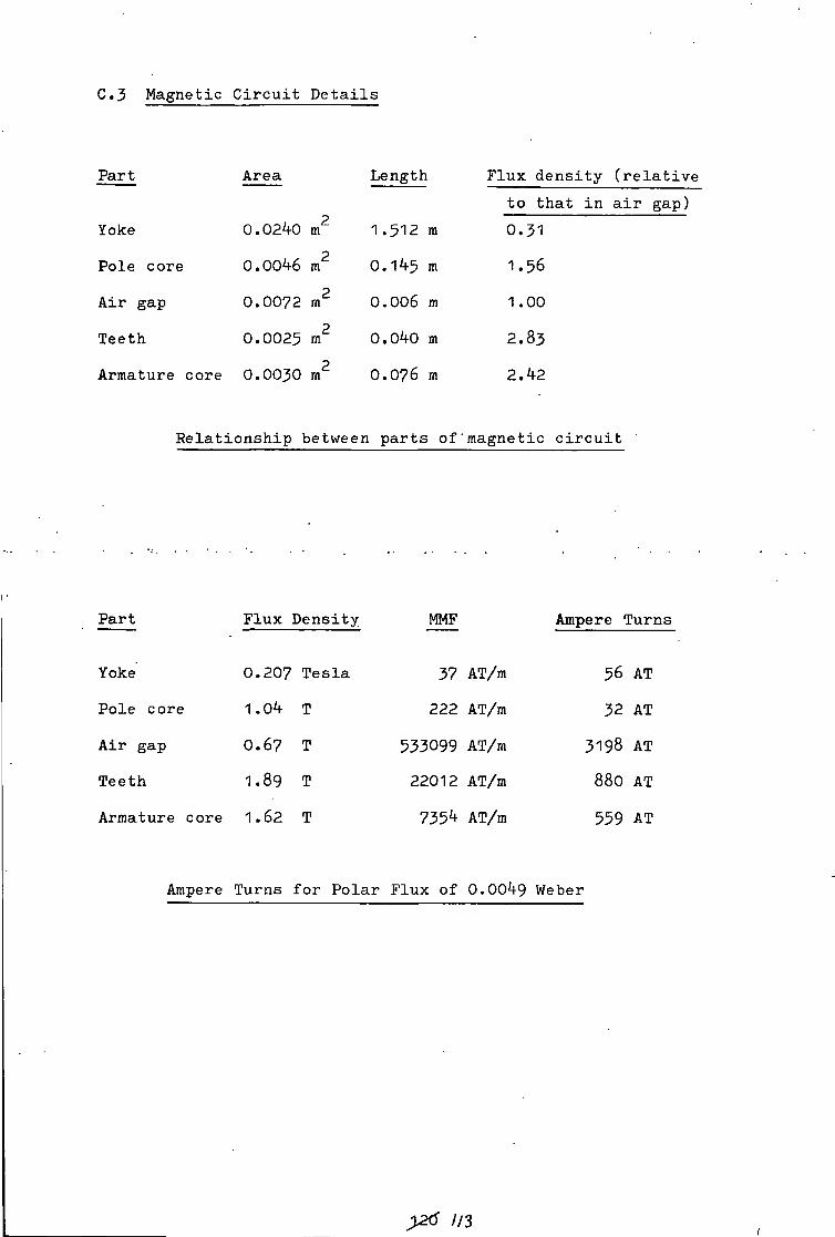
C . 3 Magnetic C i r c u i t D e t a i l s
Part Area Length F l u x d e n s i t y ( r e l a t i v e to that i n a i r gap)
Yoke 0.02*4-0 m2 1.512 m 0.31 p
Pole core 0.00^6 m 0.1^5 m 1.56
A i r gap 0 .0072 m2 0 .006 m 1.00
Teeth 0 .0025 m2 O.OkO m 2 .83 p
Armature core 0 .0030 m O.O76 m 2.^2
R e l a t i o n s h i p between p a r t s of" magnetic c i r c u i t
P a r t F l u x Density MMF Ampere Turns
Yoke 0 .207 T e s l a 37 AT/m 56 AT
Pole core 1.04 T 222 AT/m 32 AT
A i r gap O .67 T 533099 AT/m 3198 AT
Teeth 1.89 T 22012 AT/m 880 AT
Armature core 1.62 T 735^ AT/m 559 AT
Ampere Turns f or P o l a r Flux of 0.00^9 Weber
>2tf 1/3

C.k Delay Times of Control Unit
'master' c o n t r o l minimum delay 0 . 3 mS
maximum delay k.O mS
'co a r s e / f i n e ' c o n t r o l
Coarse Fine
min max
' o f f 0 . 3 6 mS
1 O . 36 mS 1 . 0 8 mS
2 1.44 mS 2 . 0 8 mS
3 2 . 3 6 mS 3 . 0 8 mS
4 3-24 mS 4 .00 mS
• 5 4 .10 mS 4 . 82 mS

References
1.1 'Commutation i n r o t a t i n g machines', I . E . E . Conf. Publ. 1 1 , 1964
1 . 2 Bates J . J . , S r i d h a r T.V. & T u s t i n A. ' P o s s i b i l i t y of
compensation of commutating emfs by voltages i n e x t e r n a l
c i r c u i t s u s i n g s e p a r a t i o n of a l t e r n a t e tappings', I . E . E .
Conf. Publ. 1 1 , 1964 , p 8 ? .
1 . 3 Bates J . J . & S.ridhar T.V. ' T h y r i s t o r a s s i s t e d s l i d i n g contact
commutation', Proc. I . E . E . , 1 9 6 6 , 1 1 3 , ( 2 ) , p 3 3 9 .
1 . 4 Bates J . J . , Stanway J . & Sansum R.F. 'Contact problems i n
machines u s i n g t h y r i s t o r a s s i s t e d commutation'
Proc. I . E . E . , 1 9 7 0 , 1 1 7 , ( 2 ) , P 3 8 7 - 3 9 7 .
1 . 5 Andrews H.I. 'Development of an e l e c t r o n i c a l l y commutated
motor with laminated brushes'
Proc. I . E . E . , 1 9 6 9 , 1 1 6 , ( 5 ) , p p 7 6 3 - 7 6 8 .
1 .6 Wilson T.G. & T r i c k e y P.H.. 'D.C. machines with s o l i d s t a t e
commutation' A.I.E.E. Conf. Paper, CP62 - 1 3 7 2 , 1 9 6 2 .
3 . 1 Jones C.V. 'An a n a l y s i s of commutation for the u n i f i e d
machine theory' Proc. I . E . E . , 1 9 5 8 , 1 0 5 C , ( 4 ) , p 4 7 6 .
3 . 2 P r e s c o t t J.C. & E l - K a r a s h i A.K. 'A method of measuring s e l f
inductances a p p l i c a b l e to large e l e c t r i c a l machines'
Proc. I . E . E . , 1 9 5 9 , 1 0 6 A , ( 4 ) , p l 6 9 .
6 .1 Moullin E.B. 'Electromagnetic P r i n c i p l e s of the Dynamo'
Oxford, 1 9 5 5 .
8 .1 Moore J.R. 'Discussion on "Contact problems i n machines usi n g
t h y r i s t o r a s s i s t e d commutation"'
Proc. I . E . E . , 1970 , 1 1 7 , ( 1 2 ) , p p 2 2 6 6 - 2 2 6 7 .
8 . 2 Bates J . J . , Stanway J . & Sansum R.F. 'Contact problems i n
machines using t h y r i s t o r a s s i s t e d commutation'
Proc. I . E . E . , 1 9 7 0 , 1 1 7 , ( 2 ) , p p 3 8 7 - 3 9 7 .
y£ us

8 . 3 Bates J . J . 'Correspondence on "Diode a s s i s t e d commutation"'
Proc. I . E . E . , 1970, 1 1 7 , ( 5 ) , p p 1 0 1 7 - 1 0 1 9 .
8 . 4 Bates J . J . ' T h y r i s t o r a s s i s t e d commutation i n e l e c t r i c a l
machines' Proc. I . E . E . , 1 9 6 8 , 115, ( 6 ) , p p 7 9 1 - 8 0 1 .
,8.^5 General E l e c t r i c .'S.C.R. Manual'
\". New York, U.S.A., 1 9 6 4 , Chapter 4 .
8 . 6 General E l e c t r i c ' T r a n s i s t o r Manual'
New York, U.S.A., 1 9 6 4 , Chapter 1 3 .
9 .1 Jones C.V. 'The U n i f i e d Theory of E l e c t r i c a l Machines'
- Butterworth, London, 1 9 6 7 , p p 3 4 9 - 3 5 2 .
A. 1 Jones C.V. 'The U n i f i e d Theory of E l e c t r i c a l Machines'
Butterworth, London, 1 9 6 7 , chapter 2 1 .
"A.2 '' Barton T.H.- & Dun f i e l d J'.C. 'Inductances of a p r a c t i c a l s l i p
r i n g p r i m i t i v e ' Trans. A.I.E.E., PAS85, 1 9 6 6 , ( 2 ) , ppl40 - 1 5 1 .
"B.1 .IBM 'Continuous System's Modelling Program' 4 t h e d i t i o n , 1969 .
B. 2 McCracken D.D. 'A guide to F o r t r a n IV programming'
Wiley, New York, 1 9 6 5 .

A c kri d w1e dgemeri t s
The author i s indebted to the f o l l o w i n g -
Dr. C. Preece for h i s continued encouragement and d i s c u s s i o n
of the work.
The acedemic s t a f f of the Department of Engineering Science
for t h e i r i n t e r e s t i n the work.
The t e c h n i c a l s t a f f of the Department of Engineering Science
for t h e i r a s s i s t a n c e i n the p r e p a r a t i o n of the experimental
equipment.
The U n i v e r s i t y of Durham f o r the use of l i b r a r y , computer and
la b o r a t o r y f a c i l i t i e s .
• The County Borough of H a r t l e p o o l .
mi
v i i i