Embed Size (px)
Citation preview

This document contains a post-print version of the paper
An Analytical Approach for Modelling Asymmetrical Hot Rolling ofHeavy Plates
authored by T. Kiefer and A. Kugi
and published in Mathematical and Computer Modelling of Dynamical Systems.
The content of this post-print version is identical to the published paper but without the publisher's �nal layout orcopy editing. Please, scroll down for the article.
Cite this article as:
T. Kiefer and A. Kugi, �An analytical approach for modelling asymmetrical hot rolling of heavy plates�, Mathematical
and Computer Modelling of Dynamical Systems, vol. 14, no. 3, pp. 249�267, 2008. doi: 10.1080/13873950701844915
BibTex entry:
% This file was created with JabRef 2.8.1.
% Encoding: Cp1252
@ARTICLE{acinpaper,
author = {Kiefer, T. and Kugi, A.},
title = {An Analytical Approach for Modelling Asymmetrical Hot Rolling of
Heavy Plates},
journal = {Mathematical and Computer Modelling of Dynamical Systems},
year = {2008},
volume = {14},
pages = {249--267},
number = {3},
doi = {10.1080/13873950701844915},
url = {http://www.tandfonline.com/doi/abs/10.1080/13873950701844915}
}
Link to original paper:
http://dx.doi.org/10.1080/13873950701844915
http://www.tandfonline.com/doi/abs/10.1080/13873950701844915
Read more ACIN papers or get this document:
http://www.acin.tuwien.ac.at/literature
Contact:
Automation and Control Institute (ACIN) Internet: www.acin.tuwien.ac.atVienna University of Technology E-mail: [email protected]
Gusshausstrasse 27-29/E376 Phone: +43 1 58801 376011040 Vienna, Austria Fax: +43 1 58801 37699
An analytical approach for modelling asymmetrical hot rolling of heavy plates
Thomas Kiefer* and Andreas Kugi
Complex Dynamical Systems Group, Automation and Control Institute, Vienna University ofTechnology, Vienna, Austria
(Received 28 January 2007; final version received 2 August 2007)
During the hot rolling process of heavy plates, asymmetries in the roll gap due todifferent circumferential velocities, different work roll radii or vertical temperaturegradients lead to a bending of the outgoing material. This so-called ski-effect bringsalong a degradation of the plate quality with respect to the flatness properties and maylead to problems in the further processing steps. Thus, it is aimed at designing a strategyto minimize the ski or even better to avoid the occurrence of the ski-effect. This work isdevoted to the development of a mathematical model that can be used for onlineexecution in process control as a basis of a ski control concept. Although most modelsin the literature are based on numerical methods (e.g. finite elements), we will present asemi-analytical approach utilizing the upper bound theorem for ideal rigid-plasticmaterials. Starting from a detailed model, simplifications are made to decrease theexecution time. The results thus obtained are compared both with numerical data fromfinite element simulations and measurement data taken in a rolling mill by CCD-camerameasurements.
Keywords: ski-ends; hot rolling; upper bound method
1. Introduction
In heavy plate mills, the demands on product thickness and flatness quality are steadilyincreasing. The quality is primarily influenced by the processing at the finishing mill standwhere the thickness of plates of different widths and lengths is decreased in several passes.As a consequence, the improvement of the process control is a permanent subject ofresearch. In the last years it has turned out that especially the development of accuratephysics-based models that serve as a basis for the controller design and for the systemoptimization leads to very good results in view of a further improvement of the productquality.
One form of flatness defects that often occurs during hot rolling of plates is the frontend bending of the rolled plates resulting from asymmetries in the roll gap, for examplecaused by different circumferential velocities of the work rolls, different frictionparameters or by a vertical temperature gradient. Due to the form of the bended platethis effect is sometimes also referred to as the ski-effect. In addition to the decrease in theproduct quality, large ski-ends may even damage the roller table and the measuringequipments behind the roll gap and are known to cause severe problems in the further
*Corresponding author. Email: [email protected]
Mathematical and Computer Modelling of Dynamical Systems
2008, 1–19, iFirst article
ISSN 1387-3954 print/ISSN 1744-5051 online
� 2008 Taylor & Francis
DOI: 10.1080/13873950701844915
http://www.informaworld.com
Post-print version of the article: T. Kiefer and A. Kugi, �An analytical approach for modelling asymmetrical hot rolling of heavy plates�,
Mathematical and Computer Modelling of Dynamical Systems, vol. 14, no. 3, pp. 249�267, 2008. doi: 10.1080/13873950701844915
The content of this post-print version is identical to the published paper but without the publisher's �nal layout or copy editing.

processing steps, for example at the hot leveler and in the cooling zone. Consequently,the ski-effect has to be avoided or at least minimized by the use of an effective controlconcept.
In general, the ski-effect can be quantified by the curvature of the outgoing plate ends.The interesting point of the front end bending phenomenon is the fact that the curvaturedepends not only on the asymmetries themselves but also on the geometry of the roll gap.In particular, it turns out that for identical asymmetrical rolling conditions the curvatureeven changes sign when rolling plates of different thicknesses with different thicknessreductions. In this context, the so-called shape factor, that is the ratio of the arc length ofcontact to the medium plate thickness, is usually used to characterize the roll gapgeometry. If we take for example the case of rolling a homogeneous plate where the onlyasymmetry in the roll gap is due to different circumferential velocities of the work rolls,then, as one would intuitively expect, the plate tends to bend away from the faster workroll for small shape factors. In contrast to this, for larger shape factors, the curvaturechanges sign and the plate bends toward the faster work roll.
Clearly, a mathematical model has to be able to describe this effect to serve as asuitable basis for designing control strategies to avoid front end bending in the hot rollingprocess. Several methods for predicting the curvature of the rolled material can be foundin the literature. In general, these models are only of limited benefit in process controlbecause either the computational costs are too high or the models are not accurate enoughto describe the basic phenomena as discussed above. In this article, we will present aphysically motivated mathematical model of the front end bending phenomenon that hasproven to be a good compromise between a high degree of accuracy and lowcomputational costs for executing the model in the process control unit. We willespecially focus on the influence of an asymmetry in the work roll circumferential speedsbecause such a difference can be used later on as a control input for the avoidance of ski-ends, see [1,2].
The article is organized as follows: in Section 2 we will have a closer look at theliterature dealing with this subject. This will also give an explanation for the choice of themethods being used in this work to model the ski-effect. The mathematical model ofthe asymmetrical roll gap is based on the upper bound theorem for ideal rigid-plasticmaterials and will be presented in detail in Section 3. A reduction of the computationalcosts of this model can be achieved by using a simplified model that results from theanalogy between rolling and flat compression. In Section 4 these models are comparedwith finite element (FE) simulations and the results obtained with measured data taken bya CCD-camera for two characteristic plates. In Section 5, the article will close with a shortsummary and an outlook to future research activities.
2. Literature survey
Most of the early contributions in the 1950s and 1960s in the field of front end bendingwere devoted to experimental studies. Thus, for instance [3] describes asymmetrical rollingexperiments of steel and lead caused by unequal diameters of the working rolls in a piniondrive. These results were extended in [4] where the asymmetry in the roll gap results fromdifferent circumferential velocities of the work rolls or from different friction conditionson the upper and the lower rolls. All these experiments were performed with lead becausethe material properties of lead at room temperature are similar to those of steel at highertemperatures. Furthermore, in [5] different experimental results for asymmetrical hotbar rolling are presented. Summarizing, these experiments show that one of the main
2 T. Kiefer and A. Kugi
Post-print version of the article: T. Kiefer and A. Kugi, �An analytical approach for modelling asymmetrical hot rolling of heavy plates�,
Mathematical and Computer Modelling of Dynamical Systems, vol. 14, no. 3, pp. 249�267, 2008. doi: 10.1080/13873950701844915
The content of this post-print version is identical to the published paper but without the publisher's �nal layout or copy editing.

reasons for the front end bending phenomenon is a mismatch in the circumferentialvelocities of the work rolls and that the curvature strongly depends on the geometry of theroll gap.
First attempts to provide an analytical solution to the problem of the ski-effect underasymmetrical rolling conditions were given in [6,7]. The authors use the so-called slip-linefield analysis which is a method of characteristics. In this case, the characteristics are thelines of the main shear stress. This method can only be used to solve plane-strain steady-state deformation problems. The slip-line model is capable of predicting the change of signof the curvature of the outgoing material for sticking friction, but the qualitativeagreement with measured data is moderate. The application of this method to the generalproblem fails because the construction of slip-line fields can become complicated and it isknown that this method is in general still limited in predicting results that give goodcorrelations with experimental work, see [8].
In the last years, FE methods have become more and more important in thesimulation of hot rolling processes, in particular in the case of asymmetrical rollingconditions. Kobayashi et al. [8] describes the basic formulation of the FE method formetal forming and in [9] one finds the FE method applied to asymmetrical rolling. FurtherFE simulation results can be found in [10], where a mismatch in the lubrication of theupper and the lower work roll is the reason for the occurrence of the ski-ends, or in[11,12], where the main focus is laid on the investigation of the influence of different workroll circumferential velocities on the curvature of the outgoing plate. In [13], FEsimulations are compared with measured data taken in a pilot plant. In addition, [14]combines the FE results with a neural network to get an empirical model for theprediction of the curvature. The FE simulations could be reproduced by the neuralnetwork model in a quite satisfactory way. However, a drawback of this model is therestriction to the specific set of FE data used to train the neural network, an extrapolationto other plate geometries and/or other asymmetrical rolling conditions is not possible. Ingeneral, FE models allow an exact prediction of the shape of the material but the requiredexecution time constitutes the main deficiency of this approach, in particular in view of itsreal-time application in the process control unit.
In steel industries, the calculation of the shape of the rolled plate is often based on theclassical slab method where it is assumed that the cross-sectional area of the rolled platesremains plane during the rolling process. Clearly, this assumption does not apply to thehot rolling of plates, see, for example the measurements reported in [15]. Even thoughthis theory leads to feasible results for the prediction of the rolling torque and the rollingforce, it does not serve as a suitable basis for describing the front end bendingphenomenon.
To sum it up, it can be stated that all these methods have their advantages but they arenot feasible to provide a mathematical model that meets the demands on accuracy andshort execution time for process control at the same time. As a consequence, we decided touse the so-called upper bound method, which can also be found in the literature in thecontext of the front end bending phenomenon. Henceforth, we will show that thisapproach brings up a mathematical model with a good tradeoff between accuracy andcomplexity and thus execution time.
3. Modelling the ski-effect
Exact solutions for problems in metal forming processes are in general difficult toobtain. It is known from the mathematical theory of elasticity that the principles
Mathematical and Computer Modelling of Dynamical Systems 3
Post-print version of the article: T. Kiefer and A. Kugi, �An analytical approach for modelling asymmetrical hot rolling of heavy plates�,
Mathematical and Computer Modelling of Dynamical Systems, vol. 14, no. 3, pp. 249�267, 2008. doi: 10.1080/13873950701844915
The content of this post-print version is identical to the published paper but without the publisher's �nal layout or copy editing.
of minimum of potential energy can be used to provide good results for diffi-cult boundary value problems. Similar methods are also valid for plastic materials. Therole of these extremum principles in plasticity is steadily increasing because theyalso serve as a basis for the numerical solution of problems in plasticity, for examplein FE simulations as shown in [8] Apart from their relevance for numerical appli-cations the extremum principles can also be used to calculate approximate solutionsof metal forming problems. We will take advantage of this fact for the derivation ofa semi-analytical model for the problem of front end bending in the hot rollingprocess.
In the theory of plasticity, there are two methods that use extremum principles,namely the upper bound and the lower bound method, see, for example [8,16,17].In the theory of the lower bound method a so-called statically admissible stress fieldis assumed and optimized with respect to some free parameters. It can be shown thatany statically admissible stress field yields a lower bound for the total power ofdeformation, see, for example [17]. The drawback of this method lies in the factthat one has to guess a statically admissible stress field which is in general difficult toobtain.
Therefore, we will use the upper bound method (UBM). Thereby, we have to determinea so-called kinematically admissible velocity field, that is a velocity field satisfying thecontinuity equation and the velocity boundary conditions, where some of the parametersare not directly fixed. These parameters are referred to as pseudo-independent parameters.The extremum principle guarantees that any kinematically admissible velocity field yieldsan upper bound for the total power of deformation, see, for example [17]. In the UBM thepseudo-independent parameters of the kinematically admissible velocity field aredetermined by minimizing the total power of deformation with respect to theseparameters. The so-obtained resulting kinematically admissible velocity field is assumedto be close to the real velocity field and serves as a basis for calculating the curvature of theoutgoing plate ends.
In the present contribution, we use the upper bound theorem for ideal rigid-plasticmaterials to derive a semi-analytical model for the asymmetrical hot rolling process ofheavy plates. As one might expect, the crucial point in the application of the UBM is theformulation of a suitable kinematically admissible velocity field. An approach fordescribing asymmetrical rolling using the UBM can be found in [18] where a streamfunction is used to derive a kinematically admissible velocity field. In this contribution,we will use polynomial velocity fields as ansatz functions. In a first attempt, this velocityfield is formulated in such a way that the roll gap geometry including its boundaries isdescribed as exact as possible. This leads to a model with five pseudo-independentparameters that can be evaluated in a few seconds. For process control, we will use asimplified velocity field with four pseudo-independent parameters similar to thatpresented in [19] taking advantage of the analogy between rolling and flat compression.The resulting expression for the total power of deformation can be minimized within300 ms on a standard PC. The models are compared with each other and it turns outthat the accuracy of the simplified model suffices to describe the asymmetrical rollingprocess.
Before starting with the derivation of the model, we must have a closer look at thebasic relations that are necessary to formulate the total power of deformation, which is thebasis for the application of the upper bound theorem. After these preliminaries ofplasticity theory, we will present a detailed and a simplified model utilizing the upperbound method.
4 T. Kiefer and A. Kugi
Post-print version of the article: T. Kiefer and A. Kugi, �An analytical approach for modelling asymmetrical hot rolling of heavy plates�,
Mathematical and Computer Modelling of Dynamical Systems, vol. 14, no. 3, pp. 249�267, 2008. doi: 10.1080/13873950701844915
The content of this post-print version is identical to the published paper but without the publisher's �nal layout or copy editing.

3.1. Basic preliminaries of plasticity theory
In the following we will consider a three-dimensional Euclidean space with coordinatesx ¼ (x1, x2, x3). For a more general formulation the reader is referred to [20]. Let u denotethe (spatial) velocity with the components ui ¼ @
@t xi; i ¼ 1; 2; 3. Then the equation of
continuity reads as
_rþ rdivðuÞ ¼ 0 ð1Þ
with the mass density r(x,t), the divergence operator div and _r ¼ @@trþ
P3j¼1 u
j @@xj r. If we
take into account the external body force b(x,t) the balance of momentum yields
r _u ¼ rbþ divðsÞ ð2Þ
with the Cauchy stress tensor s and _ui ¼ @@t u
i þP3
j¼1 uj @@xj u
i.For the investigation of the plastic deformation regime we consider the (quasi-)static
case, that is _u ¼ 0. Furthermore, the external body force b(x,t), which in our case is thegravitational force, is negligible and the material is assumed to be incompressible, that isr is constant. Under these assumptions the equation of continuity (1) and the balance ofmomentum (2) expressed in Euclidean coordinates x simplify to
X3j¼1
@uj
@xj¼ 0 and
X3j¼1
@sij
@xj¼ 0; i ¼ 1; 2; 3; ð3Þ
where sij ¼ sji, i 6¼ j ¼ 1,2,3 denote the components of the Cauchy stress tensor s. In theliterature the first equation in (3) is also referred to as the incompressibility condition andthe second equations are known as the equations of equilibrium.
Next we will summarize the constitutive relations of a rigid-plastic material.Thereby, it is assumed that the yielding of the material is unaffected by a hydrostaticpressure or tension [16,21]. The hydrostatic component sm of the stress s is given bythe relation
sm ¼1
3s11 þ s22 þ s33� �
: ð4Þ
Thus, for the formulation of the constitutive equations only the deviatoric stresscomponents
�sij ¼ sij � dijsm; ð5Þ
with the Kronecker delta dij ¼ 1 for i ¼ j and dij ¼ 0 otherwise, are taken into account.The so-called yield criterion of von Mises [16,22–24] states that yielding occurs when thesecond invariant J2;�s of the deviatoric stress tensor �s, given by the relation
J2;�s ¼1
2
X3i¼1
X3j¼1
�sij�sij; ð6Þ
Mathematical and Computer Modelling of Dynamical Systems 5
Post-print version of the article: T. Kiefer and A. Kugi, �An analytical approach for modelling asymmetrical hot rolling of heavy plates�,
Mathematical and Computer Modelling of Dynamical Systems, vol. 14, no. 3, pp. 249�267, 2008. doi: 10.1080/13873950701844915
The content of this post-print version is identical to the published paper but without the publisher's �nal layout or copy editing.

reaches the critical value (k)2 with the shear yield stress k
J2;�s ¼ ðkÞ2: ð7Þ
Furthermore, it is known that the shear yield stress k is related to the yield stress kf (fortension) via kf ¼
ffiffiffi3p
k. In the plastically deformed regions the constitutive equation isgiven by a relationship between the deviatoric stress �s and the so-called strain-rate tensoror rate-of-deformation tensor d whose components are defined in the form
dij ¼1
2
@ui
@xjþ @u
j
@xi
� �: ð8Þ
In the literature this constitutive equation for the plastic deformation is also referred toas the flow rule. Henceforth, we will use the flow rule of Levy and von Mises given in[8,21,24]
�sij ¼ kffiffiffiffiffiffiffiffiJ2;d
p dij with J2;d ¼1
2
X3k¼1
X3l¼1
dkldkl: ð9Þ
3.2. Upper bound theorem
Let us assume that in the considered region with the volume V the surface velocities andtractions are such that the entire material is in a state of plastic flow. Then, the total powerof deformation comprises three parts. The first part describes the internal power ofdeformation and is given by
PV ¼ZV
X3i¼1
X3j¼1
sijdijdv ¼ZV
X3i¼1
X3j¼1
�sij þ dijsm� �
dijdv
¼ZV
X3i¼1
X3j¼1
�sijdijdv ð10Þ
with the volume element dv. Note that for the last equality in equation (10) theincompressibility condition from equation (3)
P3j¼1
@uj
@xj ¼P3
i¼1P3
j¼1 dijdij ¼ 0 was used.
Inserting the flow rule of Levy and von Mises due to equation (9) into equation (10), weobtain
PV ¼ffiffiffi2p
k
ZV
ffiffiffiffiffiffiffiffiffiffiffiffiffiffiffiffiffiffiffiffiffiffiffiffiffiX3i¼1
X3j¼1
dijdij
vuut dv: ð11Þ
The second part of the total power of deformation is due to the shear losses at theboundary surface Sd where tangential discontinuities in the velocity field do occur.
6 T. Kiefer and A. Kugi
Post-print version of the article: T. Kiefer and A. Kugi, �An analytical approach for modelling asymmetrical hot rolling of heavy plates�,
Mathematical and Computer Modelling of Dynamical Systems, vol. 14, no. 3, pp. 249�267, 2008. doi: 10.1080/13873950701844915
The content of this post-print version is identical to the published paper but without the publisher's �nal layout or copy editing.

With jDuSdj as the amount of tangential velocity discontinuity along the surface Sd we get
for the shear losses the relation
PSd¼ k
ZSd
jDuSdjds ð12Þ
with the area element ds. The friction losses at the contact surface Sw of the workpiece anda tool constitute the third part. Thereby, the power dissipated on the contact surface takesthe form
PSw¼ZSw
tfjDuSwjds; ð13Þ
where jDuSwj denotes the amount of tangential velocity discontinuity between the
workpiece and the tool and tf is the frictional stress on the contact surface Sw. Clearly,the power balance ensures that the power Pext supplied by the work tool (in ourcase the work rolls) is equivalent to the total power of deformation, that isPext ¼ PV þ PSd
þ PSw.
As already mentioned in the introductory part of this section the components u i of avelocity field are called kinematically admissible if they satisfy the incompressibilitycondition from equation (3) throughout the body and those boundary conditions where acertain surface velocity is prescribed. Then the extremum principle of the UBM guaranteesthat for any kinematically admissible velocity field the following inequality holds, see, forexample [8,17]
Pext � ~PV þ ~PSdþ ~PSw
: ð14Þ
Here ~PV; ~PSdand ~PSw
stand for the expressions of equations (11)–(13) evaluated forui ¼ u i. To get a good approximation of the actual velocity field a kinematicallyadmissible velocity field with free parameters, the so-called pseudo-independentparameters, is chosen and the right-hand side of equation (14) is minimized with respectto these parameters.
3.3. Detailed model
Throughout the following application of the UBM to the front end bending problem somefurther assumptions have to be made to keep the complexity and the computational coststo a minimum. The lower and upper work rolls are considered to have a perfect cylindricalshape with radius R, cf. Figure 1. Thus, flattening and bending of the rolls are neglected.Furthermore, we assume a plane plastic flow in the roll gap, that is the velocities of allpoints are in planes parallel to the (x1, x2)-plane or the component of the velocity u3 ¼ 0.As a consequence of this assumption the volume or surface integrals of equations (11)–(13)simplify to surface or line integrals, respectively. In addition, no backward and no fronttension is applied to the entry and exit cross section of the plate in the roll gap. Thus, theonly external power supplied to the deformation process is due to the work rolls and isgiven by Pext ¼ Tuou þ Tlol with the roll torques Tu and Tl and the angular velocities ou
Mathematical and Computer Modelling of Dynamical Systems 7
Post-print version of the article: T. Kiefer and A. Kugi, �An analytical approach for modelling asymmetrical hot rolling of heavy plates�,
Mathematical and Computer Modelling of Dynamical Systems, vol. 14, no. 3, pp. 249�267, 2008. doi: 10.1080/13873950701844915
The content of this post-print version is identical to the published paper but without the publisher's �nal layout or copy editing.

and ol of the upper and the lower work roll. The material in the roll gap is assumed tobehave as an ideal rigid-plastic material that can be described by the flow rule of Levy andvon Mises according to Equation (9). The friction between the material in the roll gap andthe work rolls is described by a friction factor model of the form
tfu ¼ muk and tfl ¼ mlk; ð15Þ
where tfu and tfl denote the frictional stresses on the contact surface between the materialand the upper and lower work roll, respectively, and mu and ml are the so-called frictionfactors, see, for example [8].
Figure 1 depicts the roll gap geometry and the zone of plastic deformation. Fordetermining a suitable kinematically admissible velocity field, we divide the plasticdeformation zone into an upper and a lower part. Subsequently, the quantities referring tothe upper or the lower zone will be distinguished by an index u or l, respectively. For thetwo zones a 2 {u,l} we take the following ansatz for the kinematically admissible velocityfield
~u1a ¼ a1aðx1Þ x2 � x20� �
þ a2aðx1Þ
~u2a ¼ �1
2
@a1aðx1Þ@x1
x2 � x20� �2� @a2aðx1Þ
@x1x2 � x20� �
;ð16Þ
where a1a(x1) is a polynomial of third order and the function a2a(x
1) will be determined bythe boundary conditions. It can be easily seen that the velocity field in equation (16)satisfies the incompressibility condition (3) throughout the whole plastic deformation
Figure 1. Roll gap geometry for asymmetrical rolling.
8 T. Kiefer and A. Kugi
Post-print version of the article: T. Kiefer and A. Kugi, �An analytical approach for modelling asymmetrical hot rolling of heavy plates�,
Mathematical and Computer Modelling of Dynamical Systems, vol. 14, no. 3, pp. 249�267, 2008. doi: 10.1080/13873950701844915
The content of this post-print version is identical to the published paper but without the publisher's �nal layout or copy editing.

zone. The parameter x20 describes the vertical displacement of the upper and the lowerzones with respect to the symmetry axis (x1-axis), cf. Figure 1. The choice of Equation (16)also ensures that for x2 ¼ x20 the velocity component ~u2a ¼ 0 for a 2 {u,l}. Thus, theboundary �d : x2 ¼ x20 between the upper and the lower deformation zones constitutes asurface with tangential velocity discontinuity only, because the normal velocitycomponents are equal to zero.
The second demand on a velocity field to be kinematically admissible is that it has tosatisfy the velocity boundary conditions. Clearly, at the upper and lower contact zonesbetween the work rolls and the material, described by the relations (Because of theassumption of a perfect cylindrical shape of the work rolls, the real boundaries betweenthe material and the rolls are clearly described by segments of a circle. Here we take aTaylor series expansion of order 3 because only small values for x1 are necessary todescribe the contact zone in this case.)
�u : x2 ¼ juðx1Þ ¼hex2þ ðx
1Þ2
2R
�l : x2 ¼ jlðx1Þ ¼ �hex2� ðx
1Þ2
2R;
ð17Þ
the velocity must be tangential to the work roll surface. Thus, the components~u1a and ~u2a; a 2 fu; lg, have to meet the conditions
~u2a~u1a
�����a
¼ @jaðx1Þ@x1
; a 2 fu; lg: ð18Þ
Inserting Equation (16) into Equation (18) gives two ordinary differential equations of firstorder for the functions a2u(x
1) and a2l(x1) which can be solved analytically. With the eight
free parameters of the polynomials a1u(x1) and a1l(x
1) and the two integration constants ofthe solutions of the odes (18) we have 10 free parameters at our disposal to satisfy thevelocity boundary conditions. At the rigid-plastic boundary of the roll gap exit we assumethat the normal velocity components are zero, that is ~u2að0; x2Þ ¼ 0, and that the tangentialvelocity ~u1að0; x2Þ is an affine function of x2. With these assumptions we get the followingsix conditions
@a1a@x1
����x1¼0¼ 0;
@a2a@x1
����x1¼0¼ 0; a 2 fu; lg
a2uð0Þ � a2lð0Þ ¼ 0 and a1uð0Þ � a1lð0Þ ¼ 0;
ð19Þ
of which only four are linearly independent.A systematic treatment of the rigid-plastic boundary at the roll gap entry �en
u and �enl
cf. Figure 1, turns out to be much more difficult. If we were exact in our formulation wewould have to calculate the shape of this boundary and a kinematically admissible velocityfield would have to satisfy the boundary conditions ~u2a
���ena¼ 0 and ~u1a
���ena¼ uen with the
constant entry velocity uen of the rigid plate. Without going into further details here it can
Mathematical and Computer Modelling of Dynamical Systems 9
Post-print version of the article: T. Kiefer and A. Kugi, �An analytical approach for modelling asymmetrical hot rolling of heavy plates�,
Mathematical and Computer Modelling of Dynamical Systems, vol. 14, no. 3, pp. 249�267, 2008. doi: 10.1080/13873950701844915
The content of this post-print version is identical to the published paper but without the publisher's �nal layout or copy editing.
be shown that this approach leads to an algebraic equation for the determination of theboundary �en
u and �enl which cannot be solved analytically and thus drastically com-
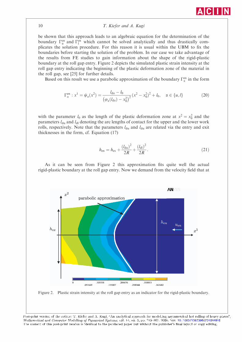
plicates the solution procedure. For this reason it is usual within the UBM to fix theboundaries before starting the solution of the problem. In our case we take advantage ofthe results from FE studies to gain information about the shape of the rigid-plasticboundary at the roll gap entry. Figure 2 depicts the simulated plastic strain intensity at theroll gap entry indicating the beginning of the plastic deformation zone of the material inthe roll gap, see [25] for further details.
Based on this result we use a parabolic approximation of the boundary �ena in the form
�ena : x1 ¼ caðx2Þ ¼
lda � l0
jaðldaÞ � x20� �2 ðx2 � x20Þ
2 þ l0; a 2 fu; lg ð20Þ
with the parameter l0 as the length of the plastic deformation zone at x2 ¼ x20 and theparameters ldu and ldl denoting the arc lengths of contact for the upper and the lower workrolls, respectively. Note that the parameters ldu and ldu are related via the entry and exitthicknesses in the form, cf. Equation (17)
hen ¼ hex þðlduÞ2
2Rþ ðldlÞ
2
2R: ð21Þ
As it can be seen from Figure 2 this approximation fits quite well the actualrigid-plastic boundary at the roll gap entry. Now we demand from the velocity field that at
Figure 2. Plastic strain intensity at the roll gap entry as an indicator for the rigid-plastic boundary.
10 T. Kiefer and A. Kugi
Post-print version of the article: T. Kiefer and A. Kugi, �An analytical approach for modelling asymmetrical hot rolling of heavy plates�,
Mathematical and Computer Modelling of Dynamical Systems, vol. 14, no. 3, pp. 249�267, 2008. doi: 10.1080/13873950701844915
The content of this post-print version is identical to the published paper but without the publisher's �nal layout or copy editing.

the contact points Cu and Cl as well as at the point Cm on the boundaries �enu and �en
l ,see Figure 1, there is no velocity discontinuity in the normal components. Theseassumptions provide four additional conditions for determining four of the 10 freeparameters of the velocity field, but further free parameters are provided by means ofldu, ldl, l0 and uen which are not independent because of Equation (21). Please keep inmind that we would have to guarantee this condition for the whole rigid-plasticboundary �en
u and �enl but with the choice of Equation (16) this turns out to be impossible.
To ensure the overall mass balance, a further parameter can be fixed by imposing thecondition
Zx20�hex=2
~u1l ð0; x2Þdx2 þZhex=2x20
~u1uð0; x2Þdx2 ¼ henuen: ð22Þ
Summarizing, we may use the following five parameters as pseudo-independentparameters in the kinematically admissible velocity field for the optimization problemwithin the UBM: the entry velocity uen, the vertical displacement x20 of the upper and thelower plastic deformation zones, the arc length of contact of the upper work roll ldu,the length l0 of the plastic deformation zone at x2 ¼ x20 and the slope a1u(0) ¼ a1l(0) of thetangential velocity ~u1að0; x2Þ at the roll gap exit. Clearly, all these parameters do have aphysical meaning and this allows us to give a physical interpretation of the optimizationresults within the UBM.
The internal power of deformation in the two deformation zones with volumes Vu andVl takes the form, cf. Equations (11) and (8),
~PVa ¼ffiffiffi2p
k
ZVa
ffiffiffiffiffiffiffiffiffiffiffiffiffiffiffiffiffiffiffiffiffiffiffiffiffiffiffiffiffiffiffiffiffiffiffiffiffiffiffiffiffiffiffiffiffiffiffiffiffiffiffiffiffiffiffiffiffiffiffiffiffiffiffiffiffiffiffiffiffiffiffiffiffi1
2
@~u1a@x2þ @~u2a@x1
� �2
þ @~u1a@x1
� �2
þ @~u2a@x2
� �2s
dv ð23Þ
with a 2 {u,l}. The power dissipated in the contact zones between the work rollsand the material, �u and �l, can be calculated by means of Equations (13) and (15) in theform
~P�a ¼ mak
Zlda0
Ua �ffiffiffiffiffiffiffiffiffiffiffiffiffiffiffiffiffiffiffiffiffiffiffiffiffiffið~u1aÞ
2 þ ð~u2aÞ2
q� ��a
����������ffiffiffiffiffiffiffiffiffiffiffiffiffiffiffiffiffiffiffiffiffiffiffiffiffiffiffiffiffiffiffiffiffiffi1þ @jaðx1Þ
@x1
� �2s
dx1 ð24Þ
with the circumferential velocity of the upper and lower work rolls Ua, a 2 {u,l}. FollowingEquation (12) the shear losses due to the tangential velocity discontinuities on theboundary �d between the upper and the lower deformation zone reads as
~P�d¼ k
Zl00
ð~u1u � ~u1l Þ�d
��� ���dx1: ð25Þ
Mathematical and Computer Modelling of Dynamical Systems 11
Post-print version of the article: T. Kiefer and A. Kugi, �An analytical approach for modelling asymmetrical hot rolling of heavy plates�,
Mathematical and Computer Modelling of Dynamical Systems, vol. 14, no. 3, pp. 249�267, 2008. doi: 10.1080/13873950701844915
The content of this post-print version is identical to the published paper but without the publisher's �nal layout or copy editing.
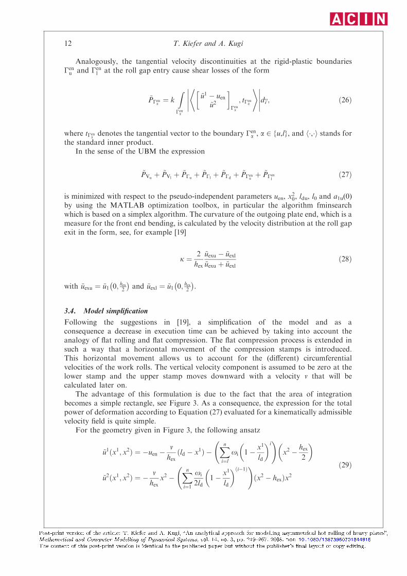
Analogously, the tangential velocity discontinuities at the rigid-plastic boundaries�enu and �en
l at the roll gap entry cause shear losses of the form
~P�ena¼ k
Z�ena
~u1 � uen~u2
� �ena
; t�ena
* +����������dg; ð26Þ
where t�enadenotes the tangential vector to the boundary �en
a , a 2 {u,l}, and h�,�i stands forthe standard inner product.
In the sense of the UBM the expression
~PVuþ ~PVl
þ ~P�uþ ~P�l
þ ~P�dþ ~P�en
uþ ~P�en
lð27Þ
is minimized with respect to the pseudo-independent parameters uen, x20, ldu, l0 and a1u(0)
by using the MATLAB optimization toolbox, in particular the algorithm fminsearchwhich is based on a simplex algorithm. The curvature of the outgoing plate end, which is ameasure for the front end bending, is calculated by the velocity distribution at the roll gapexit in the form, see, for example [19]
k ¼ 2
hex
~uexu � ~uexl~uexu þ ~uexl
ð28Þ
with ~uexu ¼ ~u1 0; hex2� �
and ~uexl ¼ ~u1 0; hex2� �
.
3.4. Model simplification
Following the suggestions in [19], a simplification of the model and as aconsequence a decrease in execution time can be achieved by taking into account theanalogy of flat rolling and flat compression. The flat compression process is extended insuch a way that a horizontal movement of the compression stamps is introduced.This horizontal movement allows us to account for the (different) circumferentialvelocities of the work rolls. The vertical velocity component is assumed to be zero at thelower stamp and the upper stamp moves downward with a velocity v that will becalculated later on.
The advantage of this formulation is due to the fact that the area of integrationbecomes a simple rectangle, see Figure 3. As a consequence, the expression for the totalpower of deformation according to Equation (27) evaluated for a kinematically admissiblevelocity field is quite simple.
For the geometry given in Figure 3, the following ansatz
~u1ðx1; x2Þ ¼ �uen �v
hexðld � x1Þ �
Xni¼l
oi 1� x1
ld
� �i !
x2 � hex2
� �
~u2ðx1; x2Þ ¼ � v
hexx2 �
Xni¼1
oi
2ld1� x1
ld
� �ði�1Þ !ðx2 � hexÞx2
ð29Þ
12 T. Kiefer and A. Kugi
Post-print version of the article: T. Kiefer and A. Kugi, �An analytical approach for modelling asymmetrical hot rolling of heavy plates�,
Mathematical and Computer Modelling of Dynamical Systems, vol. 14, no. 3, pp. 249�267, 2008. doi: 10.1080/13873950701844915
The content of this post-print version is identical to the published paper but without the publisher's �nal layout or copy editing.

is taken as a suitable choice for a kinematically admissible velocity field, see also [19].Thereby, ld denotes the average arc length of contact and oi, i ¼ 1, . . . , n, constitute thepseudo-independent parameters for minimizing the total power of deformation.
It can be easily verified that the velocity field (29) satisfies the incompressibilitycondition @~u1
@x1þ @~u2
@x2¼ 0, cf. (3), as well as the velocity boundary conditions
~u2ðx1; 0Þ ¼ 0; ~u2ðx1; hexÞ ¼ �v and ~u1ðld; x2Þ ¼ �uen; ð30Þ
as it is required for (u1,u2) to be kinematically admissible. To ensure that the overall massbalance of flat rolling is fulfilled, cf. Figure 1, the velocity v in Figure 3 is chosen to satisfythe relation
Zhex0
~u1ð0; x2Þdx2 ¼ �hexuen � vld ¼ �henuen: ð31Þ
Thus, we get
v ¼ uenhen � hex
ld: ð32Þ
The velocity field (29) can now be used to calculate the total power of deformation. ~PV
is according to Equations (8), (11) and (23). In contrast to the detailed model of Section3.3, the integration limits of the double integral are now constant values. The expressionfor the power dissipated in the contact zones between the work rolls and the materialaccording to Equations (13), (15) and (24) simplifies to
~P�a ¼ mak
Zld0
Ua � j~u1aj�� ��dx1; a 2 fu; lg ð33Þ
with ~u1u ¼ ~u1ðx1; hexÞ; ~u1l ¼ ~u1ðx1; 0Þ and the circumferential velocity of the upper and lowerwork rolls Ua, a 2 {u,l}. Summarizing, the total power of deformation reads as
~PV þ ~P�uþ ~P�l
ð34Þ
Figure 3. Simplified roll gap geometry for the analogy between rolling and flat compression.
Mathematical and Computer Modelling of Dynamical Systems 13
Post-print version of the article: T. Kiefer and A. Kugi, �An analytical approach for modelling asymmetrical hot rolling of heavy plates�,
Mathematical and Computer Modelling of Dynamical Systems, vol. 14, no. 3, pp. 249�267, 2008. doi: 10.1080/13873950701844915
The content of this post-print version is identical to the published paper but without the publisher's �nal layout or copy editing.
and can again be minimized w.r.t. the pseudo-independent parameters by means of theMATLAB optimization toolbox. In our case, the pseudo-independent parameters arechosen to be uen and oi, i ¼ 1, . . . , n. It turns out that the choice n ¼ 3 for the polynomialansatz functions (29) leads to accurate results with a significant decrease in the executiontime. The curvature of the outgoing plate end is again calculated from the velocitydistribution at the roll gap exit by the use of Equation (28).
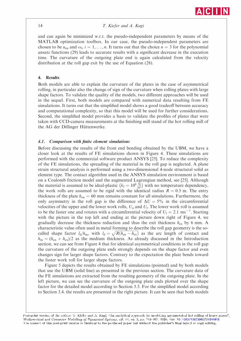
4. Results
Both models are able to explain the curvature of the plates in the case of asymmetricalrolling, in particular also the change of sign of the curvature when rolling plates with largeshape factors. To validate the quality of the models, two different approaches will be usedin the sequel. First, both models are compared with numerical data resulting from FEsimulations. It turns out that the simplified model shows a good tradeoff between accuracyand computational complexity, so that this model will be used for further considerations.Second, the simplified model provides a basis to validate the profiles of plates that weretaken with CCD-camera measurements at the finishing mill stand of the hot rolling mill ofthe AG der Dillinger Huttenwerke.
4.1. Comparison with finite element simulations
Before discussing the results of the front end bending obtained by the UBM, we have acloser look at the results of FE simulations shown in Figure 4. These simulations areperformed with the commercial software product ANSYS [25]. To reduce the complexityof the FE simulations, the spreading of the material in the roll gap is neglected. A planestrain structural analysis is performed using a two-dimensional 4-node structural solid aselement type. The contact algorithm used in the ANSYS simulation environment is basedon a Coulomb friction model and the augmented Lagrangian method, see [25]. Althoughthe material is assumed to be ideal-plastic kf ¼ 108 N
m2
� �with no temperature dependency,
the work rolls are assumed to be rigid with the identical radius R ¼ 0.5 m. The entrythickness of the plate hen ¼ 60 mm remains constant for all simulations. Furthermore, theonly asymmetry in the roll gap is the difference of DU ¼ 5% in the circumferentialvelocities of the upper and the lower work rolls, Uu and Ul. The lower work roll is assumedto be the faster one and rotates with a circumferential velocity of Ul ¼ 2.1 ms71. Startingwith the picture in the top left and ending at the picture down right of Figure 4, wegradually decrease the thickness reduction and thus the exit thickness hex by 6 mm. Acharacteristic value often used in metal forming to describe the roll gap geometry is the so-called shape factor ld/hm, with ld ¼
ffiffiffiffiffiffiffiffiffiffiffiffiffiffiffiffiffiffiffiffiffiffiffiffiffiRðhen � hexÞ
pas the arc length of contact and
hm ¼ (hen þ hex)/2 as the medium thickness. As already discussed in the Introductionsection, we can see from Figure 4 that for identical asymmetrical conditions in the roll gapthe curvature of the outgoing plate ends strongly depends on the shape factor and evenchanges sign for larger shape factors. Contrary to the expectation the plate bends towardthe faster work roll for larger shape factors.
Figure 5 depicts the results obtained by FE simulations (pointed) and by both modelsthat use the UBM (solid line) as presented in the previous section. The curvature data ofthe FE simulations are extracted from the resulting geometry of the outgoing plate. In theleft picture, we can see the curvature of the outgoing plate ends plotted over the shapefactor for the detailed model according to Section 3.3. For the simplified model accordingto Section 3.4. the results are presented in the right picture. It can be seen that both models
14 T. Kiefer and A. Kugi
Post-print version of the article: T. Kiefer and A. Kugi, �An analytical approach for modelling asymmetrical hot rolling of heavy plates�,
Mathematical and Computer Modelling of Dynamical Systems, vol. 14, no. 3, pp. 249�267, 2008. doi: 10.1080/13873950701844915
The content of this post-print version is identical to the published paper but without the publisher's �nal layout or copy editing.

fit quite well the numerical FE results. The overall performance of the detailed modelshows it to be a little bit better, especially in the case of higher shape factors. Nevertheless,the results of the simplified model are accurate enough, particularly because most plates
Figure 5. Comparison of UBM and FE for the detailed (left) and the simplified model (right).
Figure 4. FE simulations for a constant entry thickness hen ¼ 60 mm.
Mathematical and Computer Modelling of Dynamical Systems 15
Post-print version of the article: T. Kiefer and A. Kugi, �An analytical approach for modelling asymmetrical hot rolling of heavy plates�,
Mathematical and Computer Modelling of Dynamical Systems, vol. 14, no. 3, pp. 249�267, 2008. doi: 10.1080/13873950701844915
The content of this post-print version is identical to the published paper but without the publisher's �nal layout or copy editing.

are rolled with small or medium shape factors. However, because the model should beused in process control, the advantage of less computational costs and thus shorterexecution times turns out to be the great benefit of the simplified model. Therefore, thesimplified model will be used in the next section for the validation with measured data.
4.2. Comparison with plant measurements
A measurement campaign was performed at the rolling plant of the AG der DillingerHuttenwerke during normal process conditions. As no special flatness measurement devicewas available directly behind the finishing mill stand, additional measurement devices hadto be installed. A CCD-camera with the corresponding PC-system was placed 10 m behindthe mill stand besides the roller table. With this system, a picture of the plate profile on oneside can be taken when stopping the plates in front of the camera, see Figure 6.
It is clear that only an upward bending of the plates can be observed and measuredbecause a downward bending is avoided by the roller tables. An algorithm was developedto extract a curve representing the profile of the plate ends out of this picture. Theoccurrence of the ski-ends was forced by the operator of the mill stand by manuallyadjusting different circumferential velocities of the work rolls at the beginning of the pass,see the lower two pictures in Figure 7. To restrict the influence of other parameters,pyrometers were installed below and above the roller table to measure the surfacetemperatures of the plates. The plates were chosen in such a way that there was no verticaltemperature gradient. In addition, the roughness of the rolls was measured before andafter the measurement campaign and it turned out that there was no significant differencebetween the upper and the lower work rolls. From this we postulated that the frictionconditions between the plate and the upper and the lower work rolls are pretty much thesame.
The comparison of the results of the CCD-camera measurement campaign and thesimplified UBM model are depicted in Figure 7. The velocity profile was taken at everysampling time of 4 ms to calculate the curvature due to Equation (28) and thecorresponding plate profile with the given roll gap geometry. The pictures on the righthand side show the results for a plate with an entry thickness of 99.04 mm that is rolledwith a small shape factor. As a consequence, the material bends away from the faster roll,which is in this case the lower one. In contrast to this, the pictures on the left present theresults for a plate of 36.91 mm entry thickness with a higher shape factor. In this case thematerial bends toward the faster upper roll. For both scenarios, the model predicts
Figure 6. Picture of the CCD-camera measurement campaign.
16 T. Kiefer and A. Kugi
Post-print version of the article: T. Kiefer and A. Kugi, �An analytical approach for modelling asymmetrical hot rolling of heavy plates�,
Mathematical and Computer Modelling of Dynamical Systems, vol. 14, no. 3, pp. 249�267, 2008. doi: 10.1080/13873950701844915
The content of this post-print version is identical to the published paper but without the publisher's �nal layout or copy editing.

the plate profile in an excellent way so that it is considered feasible to serve as a basis fordesigning control strategies to prevent the occurrence of ski-ends.
Note that in this work a special focus was laid on the investigation of the effects of adifference in the work roll circumferential velocities on the development of ski-endswhereas temperature effects are neglected. Clearly, an asymmetry in the temperaturedistribution may also cause the development of ski-ends as it is shown in the literature, see,for example [9,14]. The UBM model can be extended by introducing a temperaturedependency in the yield stress such that asymmetrical thermal effects are taken intoaccount, too. The calculations show that the material always bends toward the cooler partof the rolled plate which is in accordance with the practical experiences and the resultsknown from the literature, for example [9,14]. However, because we have not performedmeasurements that allow the quantitative analysis of this asymmetrical temperature effect,we will not go into further details here.
5. Summary and outlook
In this article, we have presented a physically motivated model for the description ofasymmetrical rolling of heavy plates. The method being used is based on the upper boundtheorem for ideal-plastic materials. A detailed model taking into account the exact
Figure 7. Comparison of the UBM and CCD-camera measurement results for different shapefactors.
Mathematical and Computer Modelling of Dynamical Systems 17
Post-print version of the article: T. Kiefer and A. Kugi, �An analytical approach for modelling asymmetrical hot rolling of heavy plates�,
Mathematical and Computer Modelling of Dynamical Systems, vol. 14, no. 3, pp. 249�267, 2008. doi: 10.1080/13873950701844915
The content of this post-print version is identical to the published paper but without the publisher's �nal layout or copy editing.
geometry of the plastic deformation zone in the roll gap and a simplified model exploitingthe analogy of rolling and flat compression are derived. It turns out that the simplifiedmodel suffices for the calculation of the curvature of the plate in terms of a goodcompromise between accuracy and computational complexity. The quality of the modelswas verified by means of FE simulations and measurement data from a CCD-camerainstalled at the finishing mill stand at the AG der Dillinger Huttenwerke. The futureresearch activities are focused on the design and the implementation of a control strategybased on the models presented in this contribution to avoid or at least minimize theoccurrence of ski-ends.
Acknowledgements
The authors thank the AG der Dillinger Huttenwerke for funding this project and for the fruitfulcooperation. They especially thank Mr. Olivier Fichet, Mr. Burkhard Bodefeld and Dr. MarkusPhilipp for the very helpful discussions.
References
[1] T. Kiefer and A. Kugi, Modeling and control of front end bending in heavy plate mills,in Proceedings of the 12th IFAC Symposium on Automation in Mining, Mineral and MetalProcessing (IFAC MMM’07), August, 21–23, Quebec, Canada 2007, pp. 231–236.
[2] T. Kiefer, A. Kugi, R. Heeg, O. Fichet, B. Bodefeld, and L. Irastorza, Control of front endbending in heavy plate mills based on analytical models, in Proceedings of the METECInSteelCon 2007, June, 11–15, Dusseldorf, Germany, 2007.
[3] A. Chekmarev and A. Nefedov, Rolling with unequal diameter rolls, Orabotka MetallovDavleniem 4 (1956), pp. 2–15.
[4] W. Johnson and G. Needham, Further experiments in asymmetrical rolling, Int. J. Mech. Sci. 8
(1966), pp. 443–455.[5] G. Kennedy and F. Slamar, Turn-up and turn-down in hot rolling, Iron Steel Eng. 35 (1958),
pp. 71–79.[6] I. Collins and P. Dehwurst, A slipline field analysis of asymmetrical hot rolling, Int. J. Mech. Sci.
17 (1975), pp. 643–651.[7] P. Dehwurst, I. Collins, and W. Johnson, A theoretical and experimental investigation into
asymmetrical hot rolling, Int. J. Mech. Sci. 16 (1974), pp. 389–397.
[8] S. Kobayashi, S. Oh, and T. Altan, Metal Forming and the Finite-Element Method, OxfordUniversity Press, Oxford, 1989.
[9] J. Lenard, M. Pietrzyk, and L. Cser, Physical Simulation of the Properties of Hot Rolled
Products, Elsevier Science, Oxford, 1999.[10] A. Richelsen, Elastic-plastic analysis of the stress and strain distributions in asymmetric rolling,
Int. J. Mech. Sci. 39 (1997), pp. 1199–1211.
[11] M. Philipp, Front end bending in plate rolling as a result of the circumferential speed mismatch andthe shape factor. Ph.D. Thesis, University of Leoben 2002.
[12] M. Yoshii, K. Ohmori, T. Seto, H. Nikaido, H. Hishizaki, and M. Inoue, Analysis of warpingphenomenon in plate rolling, ISIJ Int. 9 (1991), pp. 973–978.
[13] A. Nilsson, Front-end bending in plate rolling, Scand. J. Metallurgy 30 (2007), pp. 337–344.[14] B. Park and S. Hwang, Analysis of front end bending in plate rolling by the Finite Element
method, J. Manufac. S. Eng. 119 (1997), pp. 314–323.
[15] A. Kneschke and H. Bandemer, Eindimensionale Theorie des Walzvorganges, in FreibergerForschungshefte, Rektor der Bergakademie Freiberg, ed., Vol. B 94, VEB Deutscher Verlag furGrundstoffindustrie, Leipzig, 1964, pp. 9–75.
[16] R. Hill, The Mathematical Theory of Plasticity, University Press Oxford, Oxford, 1986.[17] W. Prager and P. Hodge, Theory of Perfectly Plastic Solids, Chapman and Hall, London,
1951.
18 T. Kiefer and A. Kugi
Post-print version of the article: T. Kiefer and A. Kugi, �An analytical approach for modelling asymmetrical hot rolling of heavy plates�,
Mathematical and Computer Modelling of Dynamical Systems, vol. 14, no. 3, pp. 249�267, 2008. doi: 10.1080/13873950701844915
The content of this post-print version is identical to the published paper but without the publisher's �nal layout or copy editing.
[18] Y. Hwang, T. Chen, and H. Hsu, Analysis of asymmetrical clad sheet rolling by stream function
method, Int. J. Mech. Sci. 38 (1996), pp. 443–460.[19] H. Pawelski, Comparison of methods for calculating the influence of asymmetry in strip and plate
rolling, Steel Res. 71 (2000), pp. 490–496.
[20] J. Marsden, and T. Hughes, Mathematical Foundations of Elasticity, Dover, New York, 1994.[21] H. Wu, Continuum Mechanics and Plasticity, Chapman & Hall/CRC, Boca Raton, 2004.[22] Y. Basar, and D. Weichert, Nonlinear Continuum Mechanics of Solids, Springer Verlag, Berlin,
2000.
[23] A. Khan and S. Huang, Continuum Theory of Plasticity, Wiley, New York, 1995.[24] F. Ziegler, Mechanics of Solids and Fluids, Vol. 2, Springer, New York, 1997.[25] ANSYS Inc., Documentation for ANSYS Release 10.0 (Canonsburg: www.ansys.com), 2007.
Mathematical and Computer Modelling of Dynamical Systems 19
Post-print version of the article: T. Kiefer and A. Kugi, �An analytical approach for modelling asymmetrical hot rolling of heavy plates�,
Mathematical and Computer Modelling of Dynamical Systems, vol. 14, no. 3, pp. 249�267, 2008. doi: 10.1080/13873950701844915
The content of this post-print version is identical to the published paper but without the publisher's �nal layout or copy editing.