Embed Size (px)
Citation preview

An Annotated Proposed Standard for
Binary Message Transmissions within the
GOES (Geostationary Operational Environmental Satellite) DCS (Data Collection System
Revision 1
August 18,2009
Prepared for the
Satellite Telemetry Interagency Working Group (STIWG)
by
Sutron Corporation 22400 Davis Drive Sterling, VA 20164 Tel: (703) 406-2800


Table of Contents
1. INTRODUCTION ............................................................................................................................... 1
1.1 MULTIPLE LAYERS ........................................................................................................................ 2 1.2 GLOSSARY ..................................................................................................................................... 3 1.3 REFERENCES .................................................................................................................................. 3
2. DEMODULATOR VIEW OF DCP MESSAGES ............................................................................ 4
2.1 OVERALL MESSAGE STRUCTURE .................................................................................................. 4 2.2 REED SOLOMON ERROR CORRECTION .......................................................................................... 5 2.3 REQUIRED BEHAVIOR FOR DEMODULATOR SYSTEMS: ................................................................. 6
3. USER SOFTWARE TOP-LEVEL VIEW: PACKETIZED MESSAGE DATA .......................... 7
4. DESIGN CRITERIA FOR PACKET FORMATS .......................................................................... 9
4.1 THE LEGACY “STANDARD DECIMAL FORMAT” ASCII MESSAGE. ............................................... 9 4.2 BATTERY VOLTAGE ...................................................................................................................... 9 4.3 BINARY FILES ................................................................................................................................ 9 4.4 DATA COMPRESSION ................................................................................................................... 10
5. DETAILS OF PROPOSED FORMATS ......................................................................................... 11
5.1 STANDARD BINARY SHORT-INT .................................................................................................. 13 5.2 STANDARD BINARY LONG INT .................................................................................................... 15 5.3 STANDARD BINARY FLOAT ......................................................................................................... 15 5.4 STANDARD BINARY DOUBLE ...................................................................................................... 16 5.5 REFERENCE TIME ........................................................................................................................ 16 5.6 BATTERY VOLTAGE .................................................................................................................... 16 5.7 BINARY FILE ............................................................................................................................... 17 5.8 COMPACTED PSEUDO BINARY .................................................................................................... 17 5.9 COMPACTED ASCII ..................................................................................................................... 18 5.10 COMPRESSED ASCII ................................................................................................................... 19
6. OPEN ISSUES ................................................................................................................................... 20

1 Proposed DCS Binary Standard
1. Introduction The STIWG (Satellite Telemetry Interagency Working Group) has asked for recommendations for a new standard for transmitting pure binary data using the GOES (Geostationary Operational Environmental Satellite) DCS (Data Collection System). This document presents the recommendations of the Sutron Corporation.
What are the possible benefits of transmitting data in pure binary?
• Compactness: We anticipate the binary messages will provide a significant space savings, allowing the saved bandwidth to be used for other purposes. This will allow NOAA to make more assignments, or users to get more use out of their existing assignments
• Reliability: Binary error-correction schemes can be employed to greatly enhance the quality of data. Currently no error-correction is used, and the only error-detection used is a parity bit, which has a 50% chance of missing a multiple-bit error. We can do much better.
• Transparency: In this document we propose ways to encode self-describing binary DCP data. This will make it easier to implement decoding software that will work across a wide range of DCPs. It will also facilitate the sharing of DCP data between different agencies.
In order to obtain these benefits we need a strong standard that defines how data will be transmitted by the DCPs, and how messages will be processed and disseminated by GOES ground systems. This will enable the ground systems operated by many agencies (and provided by several vendors) to continue to cooperate and back each other up, as they do now.
We have gone a step further in this document. We believe it is in the interest of all users to establish stronger standards for how data is represented within a message. In the past, data formatting (in ASCII and Pseudo Binary) was left up to individual users and vendors. The result is a plethora of different formats for data representation, data description, time-tagging, etc. This has placed a large burden on agencies collecting the data. They must maintain personnel, systems, and software capable of this complex task. The standards we propose in this document will alleviate this problem.
This document is an ‘annotated proposed standard’. The DCS agencies and vendors are currently engaged in a discussion on how best to implement binary transmission. For this reason we have included explanations of why we are making these recommendations, discussions of trade-offs, etc. We anticipate that the final standard will be a more concise engineering specification.
2 Proposed DCS Binary Standard
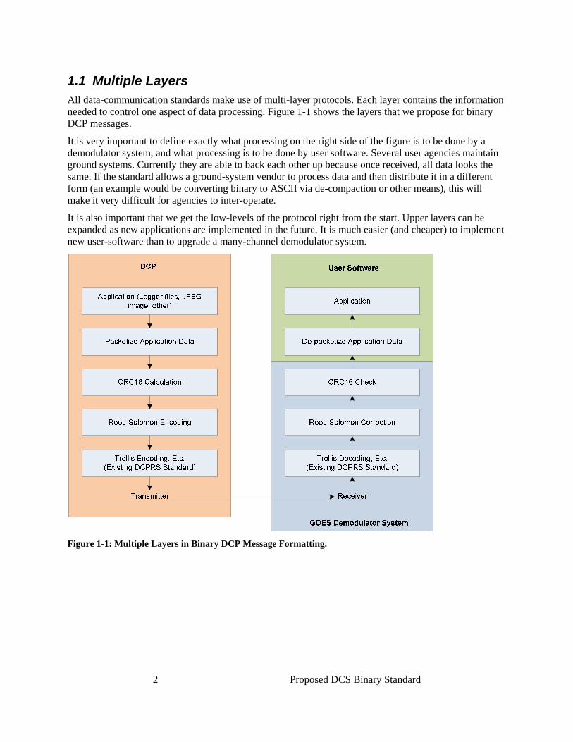
1.1 Multiple Layers All data-communication standards make use of multi-layer protocols. Each layer contains the information needed to control one aspect of data processing. Figure 1-1 shows the layers that we propose for binary DCP messages.
It is very important to define exactly what processing on the right side of the figure is to be done by a demodulator system, and what processing is to be done by user software. Several user agencies maintain ground systems. Currently they are able to back each other up because once received, all data looks the same. If the standard allows a ground-system vendor to process data and then distribute it in a different form (an example would be converting binary to ASCII via de-compaction or other means), this will make it very difficult for agencies to inter-operate.
It is also important that we get the low-levels of the protocol right from the start. Upper layers can be expanded as new applications are implemented in the future. It is much easier (and cheaper) to implement new user-software than to upgrade a many-channel demodulator system.
Figure 1-1: Multiple Layers in Binary DCP Message Formatting.

3 Proposed DCS Binary Standard
1.2 Glossary
The following acronyms are commonly used in this and other DCS-related documents:
BCH Bose, Chaudhuri, Hocquenghem – An error correction code currently used for DCP Addresses.
BPS Bits Per Second
CCITT International Telegraph and Telephone Consultative Committee
CRC Cyclic Redundancy Check
DCP Data Collection Platform
DCS Data Collection System
DCPRS Data Collection Platform Radio Set
ECC Error Correction Code (e.g. Reed Solomon)
EDC Error Detection Code (e.g. CRC)
FSS Frame Synchronization Sequence – A code transmitted at the start of each DCP message.
GOES Geostationary Operational Environmental Satellite
NESDIS National Environmental Satellite Data Information Service
NOAA National Oceanic and Atmospheric Administration
PB Pseudo Binary
R-S Reed-Solomon – a method for correcting data errors by including check-bits at the end of fixed-length packets.
STIWG Satellite Telemetry Interagency Working Group
UTC Universal Coordinated Time, equivalent to GMT (Greenwich Mean Time)
1.3 References
1. GOES Data Collection Platform Radio Set (DCPRS) Certification Standards at 300 bps and 1200 bps Version 2.0, NOAA NESDIS, Prepared by Noblis, June 1, 2008.

4 Proposed DCS Binary Standard
2. Demodulator View of DCP Messages This section describes the processing done by a GOES demodulator system to reliably receive a binary DCP message.
2.1 Overall Message Structure Figure 2-1 depicts the structure of a binary DCP message.
CRC16 EncoderFlush
Carrier .5/.25 sec
1-03 BIts FSS 15 Bits
Flag 7 bits
Msg Length14 bits
BCH 10 Bits 0
GOES ID (BCH)4 bytes
Message Data (variable length)Flag/Len (BCH)4 bytes
Existing Overhead
Top-Level View of DCP Message
F8 F7 F6 F5 F4 F3 F2Msg Format Clk Upd
MSB LSB
OddPar00 = Reserved01 = ASCII10 = Binary11 = Pseudo Binary
7-Bit Binary Flag Word
Err Correction Code
00 = None01 = R-S 255/25110 = R-S 255/23911 = R-S 255/223
unused
For ASCII or PB, 1 means Odd Parity
Optionally R-S Protected
Figure 2-1: Overall Binary DCP Message Structure.
The first part of the message, labeled “Existing Overhead” is unchanged from the current certification standards (reference 1).
Following the GOES ID is a new 4-byte BCH-encoded field labeled “Flag/Len”. It contains a 7 bit flag word and the 14-bit overall message length.
The figure also shows the individual bits of the flag word. It is important that these 7 bits immediately follow the GOES ID in order to be compatible with the current certification standards (reference 1). A demodulator system can examine these bits to determine whether the message should be treated as ASCII, Pseudo-binary, or pure binary. (The bit-numbering in the figure is to make the bits correspond to the definitions in reference 1). Bit F1 for ASCII and PB messages is unused. It is omitted for pure binary messages in order to leave 14 bits for overall message length.
Following the flag word is the message data-length as a 14-bit unsigned integer, MSB-first. This includes data and the CRC16 field following the data. Thus the data-length can range from 0 … 16381 bytes. The BCH-protected length field gives the demodulator system a reliable way of determining the number of bytes to receive, thus obviating the need for an EOT sequence.
The message length is always the number of data bytes plus the 2-byte CRC. If no Reed-Solomon (R-S) encoding is used (Bits F4/F3 = 00), then this is simply the number of bytes following the Flag/Len field.
5 Proposed DCS Binary Standard
If R-S is used, then error-correction codes (ECCs) will be embedded inside the R-S packets, as described below. The receiver must calculate the number of R-S packets being used and include the lengths of the ECC fields in the total number of bytes to receive.
2.2 Reed Solomon Error Correction Bits F4 and F3 together indicate whether Reed-Solomon error correction is used, and if so, how many check bytes are included. For example, R-S 255/239 indicates that the data is broken into packets of 255 bytes. Each packet contains 239 data-bytes and 16 check-bytes.
If R-S is used, the demodulator system must first perform the R-S correction, and then concatenate the data packets together before performing the CRC16 on the overall message.
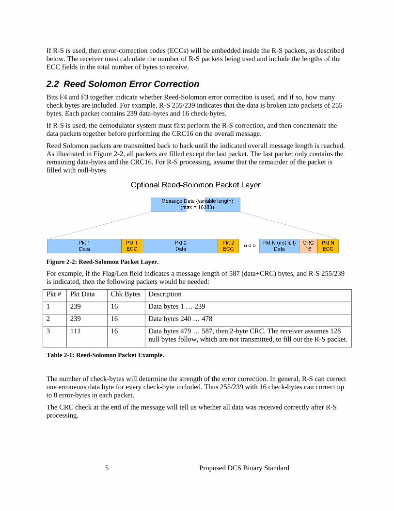
Reed Solomon packets are transmitted back to back until the indicated overall message length is reached. As illustrated in Figure 2-2, all packets are filled except the last packet. The last packet only contains the remaining data-bytes and the CRC16. For R-S processing, assume that the remainder of the packet is filled with null-bytes.
Figure 2-2: Reed-Solomon Packet Layer.
For example, if the Flag/Len field indicates a message length of 587 (data+CRC) bytes, and R-S 255/239 is indicated, then the following packets would be needed:
Pkt # Pkt Data Chk Bytes Description
1 239 16 Data bytes 1 … 239
2 239 16 Data bytes 240 … 478
3 111 16 Data bytes 479 … 587, then 2-byte CRC. The receiver assumes 128 null bytes follow, which are not transmitted, to fill out the R-S packet.
Table 2-1: Reed-Solomon Packet Example.
The number of check-bytes will determine the strength of the error correction. In general, R-S can correct one erroneous data byte for every check-byte included. Thus 255/239 with 16 check-bytes can correct up to 8 error-bytes in each packet.
The CRC check at the end of the message will tell us whether all data was received correctly after R-S processing.

6 Proposed DCS Binary Standard
The purpose for allowing 3 different strengths for R-S is to allow each user to choose the code to fit their needs:
• R-S 255/223 provides extremely strong error correction at the cost of 14.35% overhead. It can correct up to 16 erroneous bytes out of every 223. This should be selected if the user’s transmit window can accommodate the overhead.
• R-S 255/239 provides good error correction at the cost of 6.69% overhead. It can correct up to 8 erroneous bytes out of every 239.
• R-S 255/251 provides some error correction with the low cost of 1.59% overhead. It can correct up to 2 erroneous bytes out of every 251.
• The “No R-S” selection provides no error correction. The CRC16 provides error detection only. Remember that a binary data will naturally be more compact than ASCII. Thus even after adding the R-S overhead, a binary message will still be much smaller than its ASCII equivalent. The benefit is greatly enhanced reliability.
We would recommend that the normal behavior for a DCP sending a binary message is to dynamically determine the amount of overhead can be afforded given the amount of data to send, and the transmit-window size. It can then select the strongest R-S encoding that will fit.
2.3 Required Behavior for Demodulator Systems: 1. Read 32 bits following the GOES ID and attempt to perform BCH error correction:
o Following the attempt, IF bits (F7/F6) indicate that this is an ASCII or PB message, THEN continue processing the message according to the old certification standards.
o ELSE IF (F7/F6) indicate that this is a Binary message.
IF the BCH correction failed, THEN discard the entire message,
ELSE proceed with binary message processing.
2. Determine the message length from the corrected flag/len field.
3. Determine if R-S is used, and if so, what type.
4. If R-S is used, receive and correct the required number of packets to obtain the indicated number of data-bytes, as shown in the above example. Concatenate the corrected data-packets together.
5. If R-S is not used, simply receive the indicated number of data bytes.
6. Compare the received CRC to the value calculated from the data.
7. If the CRC comparison fails, this message should be marked as “containing errors”. This is equivalent to the ‘?’ parity-error designation for ASCII messages.
8. The concatenated message-data should be disseminated as-is. Demodulator systems should perform no further processing on the message data. In order to guarantee consistency of data between different ground systems, a demodulator system should not attempt to de-compact, expand, or process data within the messages.

7 Proposed DCS Binary Standard
3. User Software Top-Level View: Packetized Message Data This and following sections will discuss how data is formatted within the corrected message disseminated to users. This chapter will show how message data is divided into multiple packets, each with its own length and format indications. Following sections will discuss specific formats appropriate for various types of data.
Figure 3-1 shows how the corrected data within a DCP message is packetized. A message may have many packets. Each packet will have its own format, length, and data.
Packetized Message Data
Corrected Message Data (variable length)
PktLength
PktFormat
Pkt Data(Variable Length)
Packet 1
PktLength
PktFormat
Pkt Data(Variable Length)
Packet 2
o o o(Variable # packets)
Figure 3-1: Packetized Message Data.
The Packet Length field is the length of all data to follow in the packet, including the format indication and the variable-length data field. The Packet Length is normally a single byte, allowing packet lengths up to 254 bytes. If the length contains the value 255, then the following 2-bytes contain the extended packet length. The two possibilities are illustrated in Figure 3-2. This arrangement allows for arbitrarily long packets but still keeps the overhead for normal (short) packets very small.
Figure 3-2: Normal and Extended Length Field.
The Packet Format Field is an enumerated field that tells us:
• What type of data is being transmitted • How the data is formatted
The format field is coded in a similar manner to the length field. We anticipate that normally the packet-format can be specified in a single byte. If necessary, we reserve the value 255 to indicate that the following two bytes contain the extended format specification.

8 Proposed DCS Binary Standard
In following sections we will propose several format enumeration values. In the future, many more may be implemented and added to the standard. If the user software does not recognize the format it can use the length field to skip to the next packet. Thus new formats can be added in the future without breaking existing user-software.
We considered the addition of an error detection code like CRC8 at the end of each packet, but decided to leave it out. See Open Issue #1 at the end of this document.

9 Proposed DCS Binary Standard
4. Design Criteria for Packet Formats Before describing particular formats, this section will introduce design criteria and use-cases which will focused our efforts.
4.1 The Legacy “Standard Decimal Format” ASCII Message. There are many DCPs that currently transmit data in an ASCII format originally proposed by NESDIS called “Standard Decimal Format”. Figure 4-1 shows an example.
:HG 3 #15 13.02 13.04 9.87 9.84 13.04 13.07 13.09 13.12 :PC 3 #15 1.12 1.12 1.12 1.12 1.12 1.12 1.12 1.12 :VB 18 #60 13.2 13.1
Figure 4-1: Example of an ASCII Message in Standard Decimal Format.
This message has the advantage of being self-describing. Software (and humans) can process this message without knowing ahead of time what sensors are installed on the DCP, or what time-interval at which samples are recorded. The format is as follows:
:SensorCode Age #Interval Sample1 Sample2 … SampleN
Each sensor block starts with a colon followed by a data type code. The Age is the number of minutes to subtract from the message time to get the time-stamp for the most-recent data sample. Interval is the number of minutes between samples. Sample values are given in reverse time-order (most recent first).
There are many variations on this format. Often a name like “STAGE” or “BATTLOAD” is used instead of a data-type code. Sometimes a sign (+/-) is used instead of a space delimiter. Occasionally commas or other characters are used as delimiters. Typically the ASCII numbers can vary in length (as shown in the example when the HG goes from 13.04 to 9.87).
We would like to preserve the self-describing nature of this format, while also getting the advantage of a very compact message obtained by transmitting data in binary. Some of the proposed formats describe how this may be accomplished.
4.2 Battery Voltage Almost all DCPs transmit battery voltage in a very compact manner, typically a single value at the end of the message. We should include a binary format that accomplishes the same thing.
4.3 Binary Files Many DCPs require only a small portion of their time-window to transmit their data. A 10-second window at 300 baud can transmit over 300 characters and still leave a comfortable margin before and after the message to avoid the possibility of colliding with adjacent time-slots. A typical hydro-DCP transmitting water level and battery-voltage values will require only a small portion of this.
This leaves many bytes which might be used for something else. One possibility for “something else” would be to transmit a portion of some long binary file, like perhaps a JPEG image.

10 Proposed DCS Binary Standard
4.4 Data Compression One possibility for reducing message size is simply to compress the current ASCII or PB representation.
We elected not to include compression of a complete message because we envision that a binary message may contain a mix hydro-met and other types of data. Some types of data, such as JPEG, are already compressed. Therefore it is better to implement compression in the application-packet layer.
We did an analysis of several common compression algorithms and how they perform with the current GOES DCP traffic. The algorithms we examined were:
• LZO is a trimmed down zip-like dictionary style compression commonly used in embedded processors.
• ZIP is widely known, but for our purposes we stripped the normal file header (150 bytes). • GCP is the GoesCompress algorithm, see below. • HUF is the CompressHuffman algorithm • GCP+HUF are the two routines combined similar to how ZIP combines its dictionary algorithm with
a dynamic Huffman algorithm.
GCP is a custom compression routine that combines dictionary based compression and Huffman encoding similar in performance to the PKZIP format but customized for GOES data and with far less software overhead. GCP can eliminate both repeated strings in a message, as well as runs of repeated bytes. GCP, if accepted, will be made open source for the free use of the GOES community and other applications of the GOES message format.
The best performing algorithm in our test of ASCII and PB data was GCP+HUF. A Huffman-pass is performed to optimize the number of bits used to represent each byte according to the frequency it typically appears in the data stream. Pseudo binary and ASCII data do not use most of the available codes and hence are efficiently compressed using a Huffman encoder.
Static Huffman tables will be used to decrease complexity, processing time, and message overhead. Static tables will be provided for each standard format, and each table is 512 bytes long. GCP requires a RAM buffer to contain the compressed output data, but has little other overhead. It is capable of nearly 2:1 compression ratios over a random mix of GOES ASCII messages and over 1.5:1 on a random mix of GOES Pseudo Binary messages.

11 Proposed DCS Binary Standard
5. Details of Proposed Formats This section will describe several formats that we have identified for inclusion in the standard. The standard will allow for new formats to be identified and implemented in the future. We propose that a government entity such as STIWG serve as a registry for DCP data formats. We propose that vendors be strongly discouraged from using proprietary or non-standard packet formats. This is in keeping with the System Use Agreement that all DCS users must sign:
5. Treatment of Data All GOES DCS users must agree to permit GOES Participating Agencies, and their governments' agencies the full, open and timely use of all environmental data collected from their platforms; this may include the international distribution of environmental data under the auspices of the World Meteorological Organization. Any proprietary data will be protected in accordance with applicable laws.
Table 5-1 shows the formats that we have identified for inclusion in the initial standard. We will describe each format in subsequent sub-sections.

12 Proposed DCS Binary Standard
Fmt # Name Description
1 Standard Binary Short Int Binary version of the legacy “standard decimal format”. Self-describing. Ideal for most hydro-met data.
2 Standard Binary Long Int Identical to “Standard Binary Short Int”, except that 4-byte signed integer samples are provided. Use when greater magnitude or precision is required.
3 Standard Binary Float Similar to “Standard Binary Short Int”, except that no multiplier is used and the values are 4-byte floating point numbers. Use when the magnitude of the numbers varies widely.
4 Standard Binary Double Similar to Standard Binary Double, except that the values are 8-byte double-precision floating point numbers.
5 Reference Time Contains full date and time to millisecond resolution. The purpose is to bring the message-time-stamp in-line in the message data, without relying on the (external) time-stamp provided by the receive system.
6 Binary File Used to transmit a portion of a binary file.
7 Compressed File Used to transmit a portion of a compressed file.
8 Compacted PseudoBinary Pseudo binary data is compacted by removing the unused 2-bits of each character.
9 Compacted ASCII Transmit ASCII characters and numbers in a compact form.
10 Compressed ASCII Compressed version of any ASCII data (not restricted to a limited character set)
11 Battery Voltage Compact 1-byte representation of battery voltage
255 Expanded format Field For future expansion, when/if a single byte is not sufficient to designate the format. This means that the following 2-bytes contain the expanded format designator.
Table 5-1: Identified Data Formats for Inclusion in the Standard.

13 Proposed DCS Binary Standard
5.1 Standard Binary Short-Int “Standard Binary Short-Int” format is illustrated in Figure 5-1. This is the simplest and most compact of the binary formats. The “Pkt Data” field is shown in its expanded form. Following the figure, Table 5-2 provides an explanation of each field.
PktLength
PktFormat
Pkt Data(Variable Length)
Sensor Name(null-term string) interval Time-of-Day
(high 16 bits) T-mult Data Sample 1(16 bit signed int) Data Sample 2
o o oVariable # samples
Figure 5-1: Standard Binary Short-Int Packet Format.
Field Name Length (bytes)
Description
Sensor Name Variable Null-terminated ASCII String
Interval 1 or 3 Enumerated Value. See definitions below. If 255, then the following 2 bytes contain the interval in minutes.
Time-of-Day 2 High 16-bits of the second-of-day. The remaining bit is found in the T-mult field. Together they form a 17-bit positive integer representing the second-of-day. This determines the time-stamp for the first data sample. Note this value by definition is to be UTC.
T-mult 1 The MSB of this field is the low-bit of the Time-of-Day value. The low-order 4 bits contains a 2’s compliment signed power-of-10. (See Below).
Data Sample 2 Each data sample is transmitted as a 16-bit 2’s compliment integer value. Range: -32768 … +32767.
Table 5-2: Fields in the Standard Binary Short-Int Format.
The Interval field is an enumerated value. Table 5-3 shows one possible encoding for this field which contains most commonly used interval values. The special value 255 indicates an expanded interval field, where the following 2 bytes contain the interval in minutes (0…65535).

14 Proposed DCS Binary Standard
Value Meaning
0 Irregular Interval
1…59 # of minutes
60 1 hour
61 90 minutes
62 2 hours
63 3 hours
64 4 hours
65 6 hours
66 8 hours
67 12 hours
68 1 day
69 2 days
70 3 days
71 4 days
72 5 days
73 6 days
74 1 week
75 2 weeks
76 1 month
77 2 months
78 3 months
79 6 months
80 1 year
81 1 second
82 2 seconds
83 3 seconds
84 4 seconds
85 5 seconds
86 6 seconds
87 10 seconds
88 15 seconds
89 20 seconds
90 30 seconds
91…254 Reserved
255 Continuation – Following 2 bytes contains # minutes.
Table 5-3: Enumerated 'Interval' Values.

15 Proposed DCS Binary Standard
The “T-mult” field requires further explanation. Figure 5-2 shows how the bits are packed. The MSB of this field becomes the low-order bit for the time-of-day field to yield a full 17-bit number-of-seconds. The Time-of-Day is by-definition a second-of-day UTC.
The low 4-bits are a 2’s complement signed 4 bit number (range -8 … +7), representing the power-of-10 to multiply each data sample by. For example, the binary value 1110 translates to -2. Thus each sample would be multiplied by 10-2 or 0.01.
Figure 5-2: Bits in the T-mult Field.
Standard Binary Short-Int format is an efficient way to represent most hydro-met data. Consider the ASCII message shown above in Figure 4-1, requiring 126 bytes. The same data could be represented in binary in 28 bytes, as shown in Table 5-4.
To Transmit Pkt Overhead Fmt Overhead Data Total 8 samples of HG in Std Binary 2 7 16 25
1 sample of VB in Battery Voltage Fmt (see section 5.6) 2 0 1 3
28
Table 5-4: Binary Representation of Typical Hydro-Data.
5.2 Standard Binary Long Int This format is the same as Standard Binary Short Int (see section 5.1) except that the data values are 32-bit 2’s compliment signed integer values with range -2,147,483,648 through +2,147,483,647. It should be used in cases where a short integer provides insufficient precision.
5.3 Standard Binary Float This format is the same as Standard Binary Short Int (see section 5.1) with the following exceptions:
• Data values are 32-bit IEEE Floating Point numbers. • The “Power of 10” portion of the T-mult field is ignored.
This format should be used in cases where the magnitude of the sensor values may vary too widely for representation as an integer with fixed decimal point.

16 Proposed DCS Binary Standard
5.4 Standard Binary Double This format is the same as Standard Binary Short Int (see section 5.1) with the following exceptions:
• Data values are 64-bit IEEE Double Precision Floating Point numbers. • The “Power of 10” portion of the T-mult field is ignored. This format should be used in cases where the magnitude of sensor values may vary widely and a high level of precision is needed.
5.5 Reference Time Normally, a Message Time is transmitted as an out-of-band value provided by the receive system. It indicates the moment that the FSS (Frame Synch-Sequence) is recognized. It is passed to clients in a header external to the message-proper. Examples of these headers are DAMS-NT or DDS.
This time is important because decoding software uses the message time value in order to time-tag the data values found in the message.
For some transmission media such as Iridium or GPRS, there may be significant delay between the time a platform generates a message and when a processing system receives it. In such cases the receive-time is not sufficient. This ‘Reference Time’ packet allows the platform to provide a reliable time stamp interpreting data within a message.
Figure 5-3 shows how a full date/time value is represented in six bytes, down to millisecond accuracy. By definition this value is in UTC.
Byte:
12-bit year
Reference Time Packet Format
6-bit second6-bit minute 10-bit milliseconds4-bit
Month5-bit
Month Day
1 2 3 4
5-bit hour
5 6
Figure 5-3: Reference Time Packet Format.
5.6 Battery Voltage Battery voltage is transmitted as a 1-byte binary integer (range 0 … 255) in tenths of volts. This provides a very compact representation for a single battery voltage sample with minimal overhead.
Figure 5-4: Battery Voltage Packet Structure.

17 Proposed DCS Binary Standard
5.7 Binary File This format enables a DCP to send arbitrary data to the receiver as a “binary file”. The file is broken into packets. Portions of the file can be sent to fill up the available user’s transmit window.
Such a file might contain JPEG images, logger memory dumps, etc. This will be particularly useful in conjunction with the new DCP-Command capabilities. For example, command might tell a DCP to create a file containing a specific portion of logger memory. The DCP would dole the file out in pieces until it is entirely sent.
Figure 5-5 shows the packet structure.
Figure 5-5: Binary File Packet Structure.
The fields have the following meaning:
• File ID: Each file being transferred is assigned a 1-byte ID by the DCP. Thus multiple transfers (up to 256) might take place concurrently.
• Start Byte #: indicates where the data of this packet resides in the reconstructed file. The first packet should have byte number zero.
• FileName: The first packet contains the file name as a null-terminated string. • File Data: The remainder of the packet (up to the specified length) contains the file data.
5.8 Compacted Pseudo Binary Pseudo-binary (PB) is a data-representation whereby the low-order 6 bits of each byte contain data. The high-order 2 bits are filler. Appendix B of reference 1 contains a complete description of PB, as well as how it is commonly used to represent various types of sensor values.
In common use, an 18-bit signed or unsigned integer value is represented with 3 PB characters. For example, the number 2177 corresponds to the ASCII string “@bA”.
It should be noted that PB is simply a data compression technique, designed to make better use of transmission time while still guaranteeing that all bytes are printable ASCII characters.
It has been proposed by others that we can continue to use PB, but further compact it by discarding the 2 high-order filler bits in each byte. Thus four un-compacted PB bytes can be squeezed into 3 compacted binary bytes, yielding a 25% reduction in data length, as shown in Figure 5-6. As shown in the figure, in 3 out of 4 cases, there will be bits left over in the last byte.

18 Proposed DCS Binary Standard
Figure 5-6: Compacted Pseudo Binary Characters.
We feel that compacted PB is problematic for several reasons:
• In most cases, a 16-bit binary value will suffice, so why not just transmit 16-bit binary values? This increases our space-savings to 33%.
• As shown, there will be leftover bits in 3 out of 4 cases. If 6-bits are leftover, this leads to an ambiguity: do these bits hold data or not? This must be resolved by sending an additional length character somewhere.
• Compaction will only work for pure pseudo binary messages. Allowable PB characters include upper and lower case letters, and the characters: ?@[\]^_`{|}~. However, in practice we often see messages that contain mostly PB characters but also include other characters like spaces, digits, signs, and commas. Such hybrid messages will not be able to be compacted.
• In practice, PB data is opaque: It can hold unsigned integers, 2’s compliment integers, sign-magnitude integers, and various fixed-point representations. The length of a number can vary from 1 to four characters. This leads to problems when decoding the data and trying to share it between agencies. These problems are exacerbated by compacted PB.
However, if the DCS user community feels that a PB compaction scheme is worthwhile, it could be encoded as shown in Figure 5-7. The first byte contains the number of (un-compacted) PB characters represented by the data. This resolves the ambiguity noted above.
Figure 5-7: Packet Structure for Compacted Pseudo-Binary.
5.9 Compacted ASCII Others have proposed schemes for compacting ASCII data in a similar manner to PB. That is, establish a compact representation for common characters like digits, decimal points, and spaces; and then define a means where the representation can be expanded to accommodate less-common characters.

19 Proposed DCS Binary Standard
If the DCS user community feels that a compacted ASCII representation is worthwhile, it could easily be defined here as a separate format. However, we feel that the “Standard Binary Short Int” is a better, more compact representation for most hydro-met data. In cases where ASCII is needed, the Compressed ASCII format defined below could be used.
5.10 Compressed ASCII In section 4.4 we discussed compression algorithms. The best performing algorithm for ASCII was GCP+HUF. GCP is an algorithms that we derived and we are offering to place in the public domain. The code is very compact (about 100 lines of C-Language).
Once we determine the most effective compression algorithm for ASCII data, we can define a packet-format for it. The Packet Data will simply contain the compressed data, which must be decompressed by the user-software.

20 Proposed DCS Binary Standard
6. Open Issues 1. What should the desired behavior be for binary messages that fail the CRC16 check? Should they
be marked with the ‘?’ (like a message with parity errors), or simply discarded?
a. For ASCII messages with parity errors, at least you can see where the errors are. For binary messages you have no idea.
b. If we elect to discard such messages, then the ground system has to be able to somehow log the information that an erroneous message was received.
c. If we elect to pass on such messages, marked with a ‘?’, then we would want to add an error-detection code, like a CRC8, to the data packets described in section 3. This may allow software to determine portions of the message are good, and which are not.
i. It also may not. If format or length fields are erroneous, it may be impossible to de-packetize the message.
d. If we add CRC protection at the packet level, the existing format field could also convey if CRC is present and what type.
2. Data compression for ASCII, PB, and other types of data: We will publish our test results for various compression algorithms, run against the current GOES data stream. There should be discussion on the best algorithm to define as the standard. It might be that multiple algorithms will be supported, each with their own format number.
3. Profiler and other types of data: Several DCS users transmit wind or current profile data. This data could be thought of as a kind of matrix. For each sample-time we are presented with a vector of measurements at different altitudes (or depths). We would like to hear from users on efficient ways of representing such data, how it might be compacted, etc. This could eventually lead to new formats to be registered with STIWG under the overall standard.
This also applies to other types of data such as geomagnetic, seismic, etc. DCS standards have been criticized in the past for being too “hydro-centric”. This need not be the case for this binary standard. New data formats can easily be added to the standard after consultation with users and vendors.


![winprotocoldoc.blob.core.windows.net... · Web view[MS-MQQB]: Message Queuing (MSMQ): Message Queuing Binary Protocol. Intellectual Property Rights Notice for Open Specifications](https://img.pdfslide.net/doc/110x75/5b0ded467f8b9a952f8e3d0e/viewms-mqqb-message-queuing-msmq-message-queuing-binary-protocol-intellectual.jpg)


![Message-driven AMR Techniquesblogs.bu.edu/simac3/files/2013/11/10_Lelbach_AMR.pdf · Message-driven AMR Techniques for Binary Star Simulations Bryce Adelstein-Lelbach[1], ... •HPX](https://img.pdfslide.net/doc/110x75/5ec7f0ee818b43225b3ee810/message-driven-amr-message-driven-amr-techniques-for-binary-star-simulations-bryce.jpg)