Embed Size (px)
Citation preview
An Application of Bandpass Filters
Jeff Crawford - KZR
October 15, 2016
1
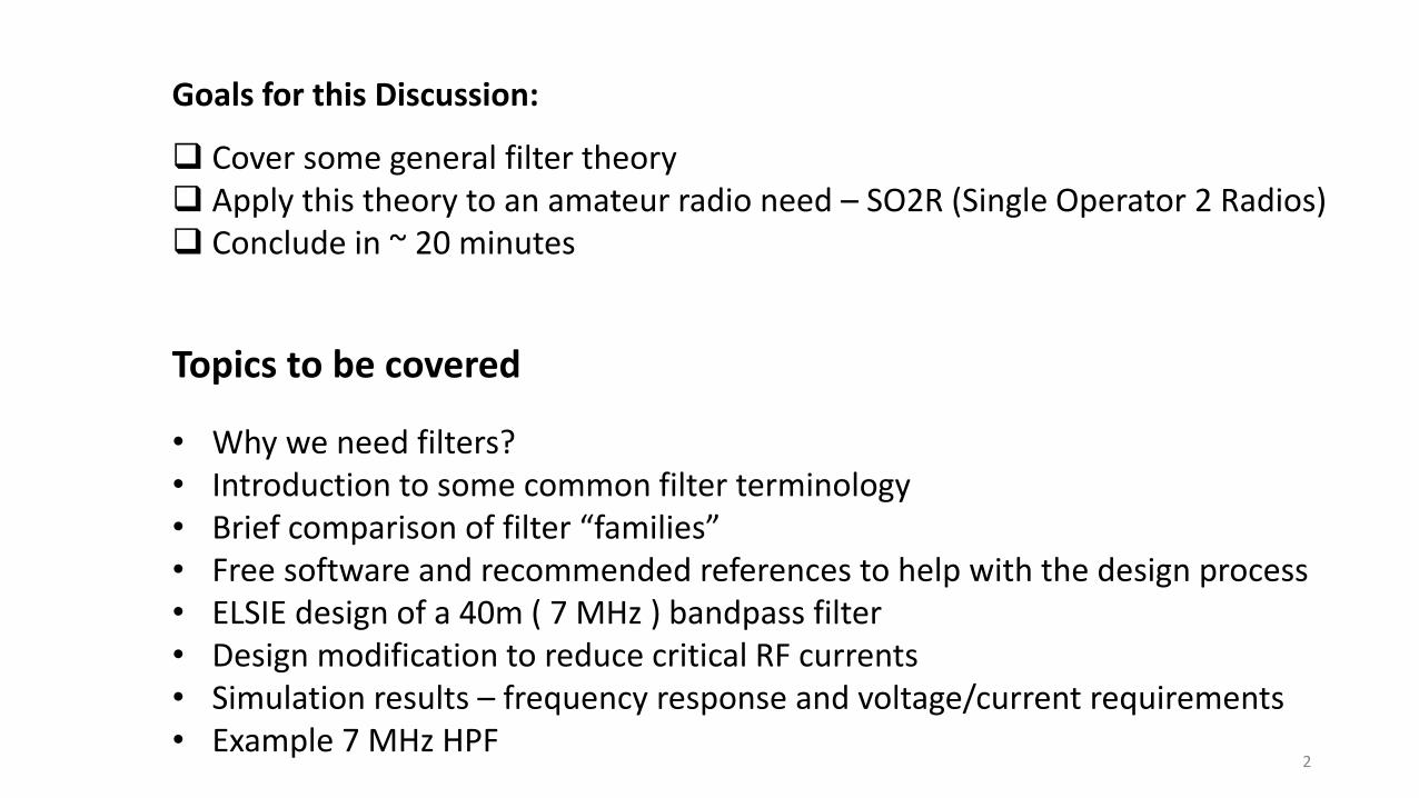
Topics to be covered
• Why we need filters?• Introduction to some common filter terminology• Brief comparison of filter “families”• Free software and recommended references to help with the design process• ELSIE design of a 40m ( 7 MHz ) bandpass filter• Design modification to reduce critical RF currents• Simulation results – frequency response and voltage/current requirements• Example 7 MHz HPF
Goals for this Discussion:
Cover some general filter theory Apply this theory to an amateur radio need – SO2R (Single Operator 2 Radios) Conclude in ~ 20 minutes
2
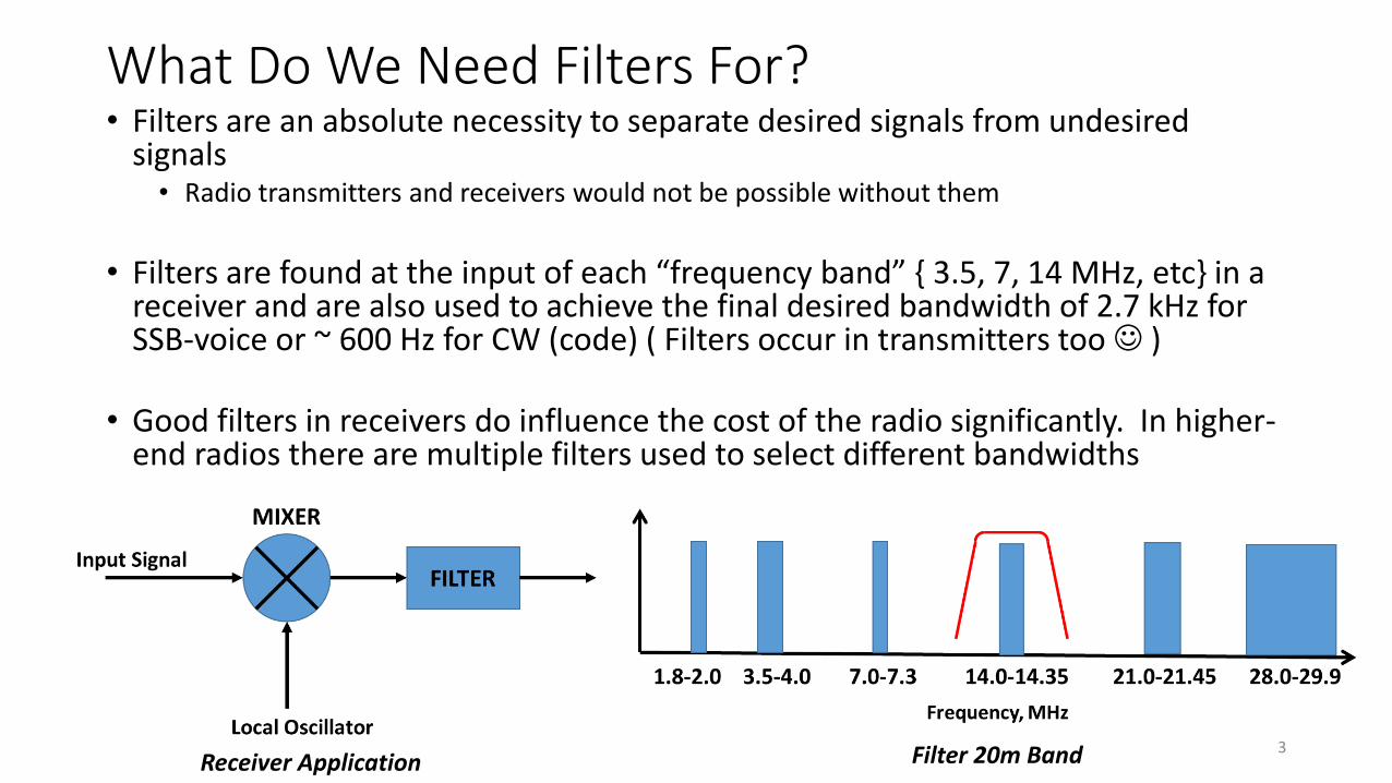
What Do We Need Filters For?• Filters are an absolute necessity to separate desired signals from undesired
signals• Radio transmitters and receivers would not be possible without them
• Filters are found at the input of each “frequency band” { 3.5, 7, 14 MHz, etc} in a receiver and are also used to achieve the final desired bandwidth of 2.7 kHz for SSB-voice or ~ 600 Hz for CW (code) ( Filters occur in transmitters too )
• Good filters in receivers do influence the cost of the radio significantly. In higher-end radios there are multiple filters used to select different bandwidths
Receiver Application Filter 20m Band 3
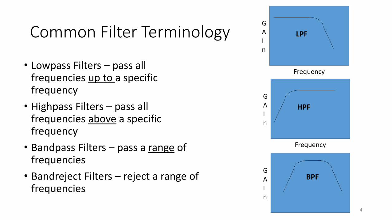
Common Filter Terminology
• Lowpass Filters – pass all frequencies up to a specific frequency
• Highpass Filters – pass all frequencies above a specific frequency
• Bandpass Filters – pass a range of frequencies
• Bandreject Filters – reject a range of frequencies
Frequency
GAIn
LPF
Frequency
GAIn
HPF
GAIn
BPF
4
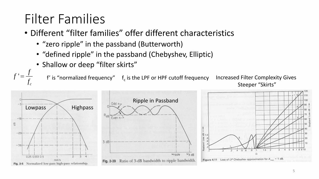
Filter Families• Different “filter families” offer different characteristics
• “zero ripple” in the passband (Butterworth)
• “defined ripple” in the passband (Chebyshev, Elliptic)
• Shallow or deep “filter skirts”
HighpassLowpassRipple in Passband
Increased Filter Complexity GivesSteeper “Skirts”
5
'c
ff
f f’ is “normalized frequency” fc is the LPF or HPF cutoff frequency
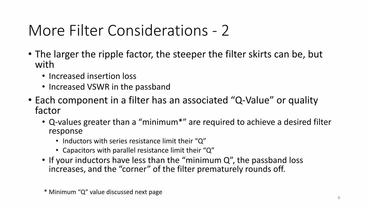
More Filter Considerations - 2
• The larger the ripple factor, the steeper the filter skirts can be, but with• Increased insertion loss• Increased VSWR in the passband
• Each component in a filter has an associated “Q-Value” or quality factor• Q-values greater than a “minimum*” are required to achieve a desired filter
response• Inductors with series resistance limit their “Q”• Capacitors with parallel resistance limit their “Q”
• If your inductors have less than the “minimum Q”, the passband loss increases, and the “corner” of the filter prematurely rounds off.
6* Minimum “Q” value discussed next page
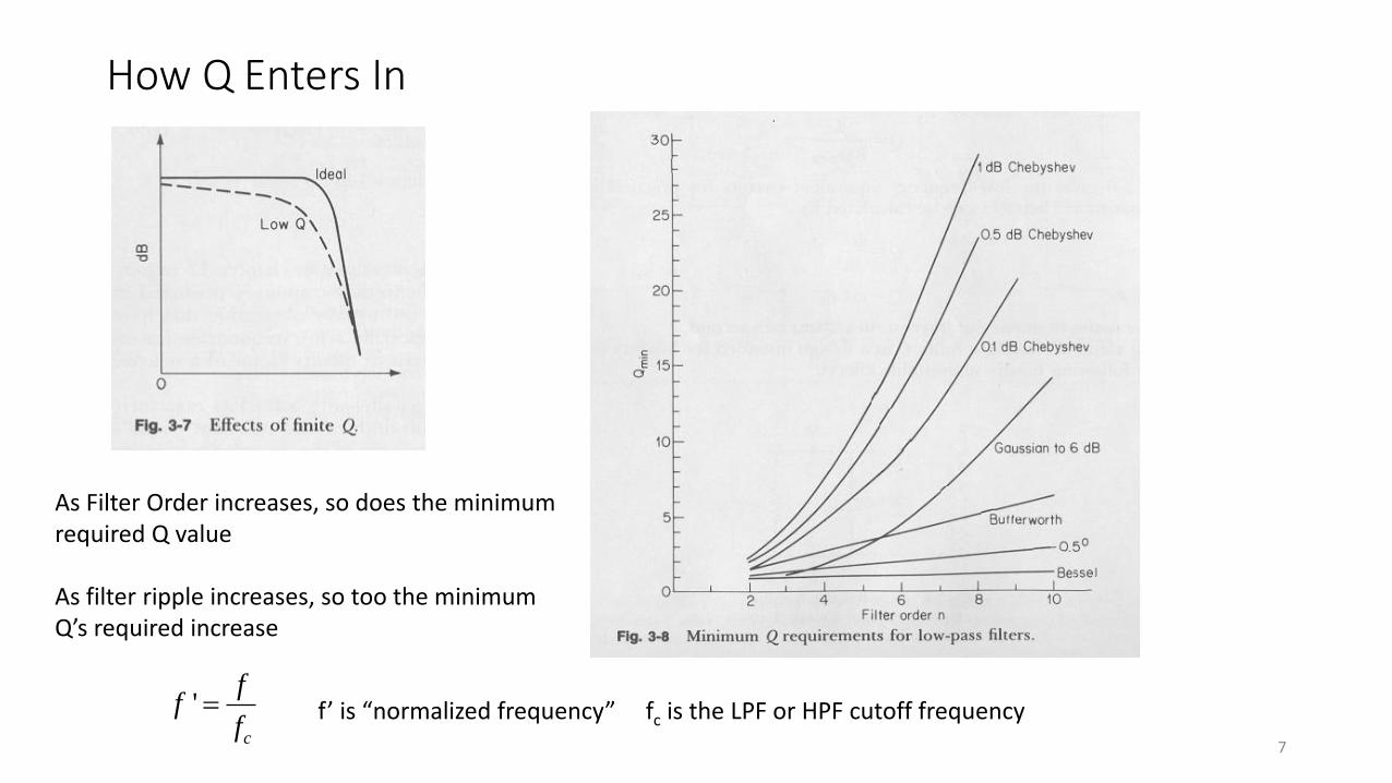
How Q Enters In
As Filter Order increases, so does the minimumrequired Q value
As filter ripple increases, so too the minimumQ’s required increase
7
'c
ff
f f’ is “normalized frequency” fc is the LPF or HPF cutoff frequency
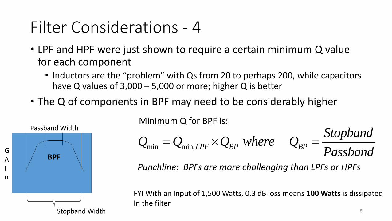
Filter Considerations - 4• LPF and HPF were just shown to require a certain minimum Q value
for each component• Inductors are the “problem” with Qs from 20 to perhaps 200, while capacitors
have Q values of 3,000 – 5,000 or more; higher Q is better
• The Q of components in BPF may need to be considerably higher
Stopband Width
Passband WidthMinimum Q for BPF is:
min min,LPF BP BP
StopbandQ Q Q where Q
Passband
Punchline: BPFs are more challenging than LPFs or HPFs
8
FYI With an Input of 1,500 Watts, 0.3 dB loss means 100 Watts is dissipatedIn the filter
Resources for Filter Work
• ELSIE – “free” filter design software on the web, up to 7th order filters
• LTSpice – “free” circuit simulator to analyze your filters (and other circuits)
• ORCAD Lite – “free” SPICE analysis software
• MicroCap
• DXZone – Filter design
• DesignSpark PCB for PCB layout (not limited to 3” x 4” like many other programs)
References:
• Electronic Filter Design Handbook, Arthur B. Williams, McGraw-Hill
• Principles of Active Network Synthesis and Design, Gobind Daryanani, John Wiley
• Electrical Filters, Donald White, Don White Consultants
9
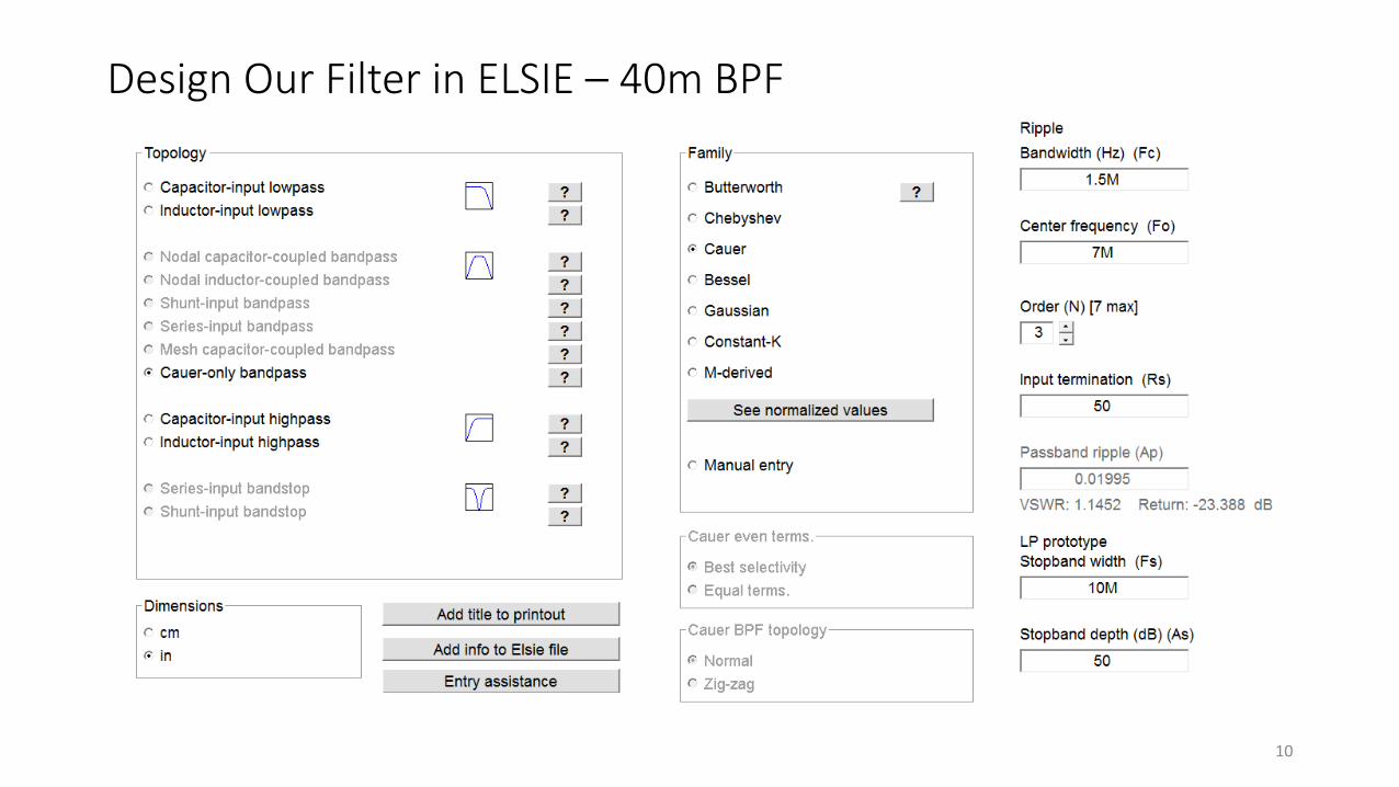
Design Our Filter in ELSIE – 40m BPF
10
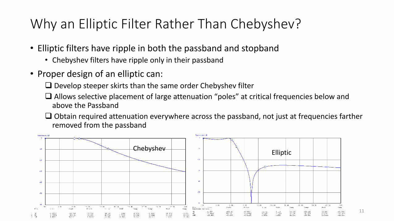
Why an Elliptic Filter Rather Than Chebyshev?
• Elliptic filters have ripple in both the passband and stopband• Chebyshev filters have ripple only in their passband
• Proper design of an elliptic can: Develop steeper skirts than the same order Chebyshev filter
Allows selective placement of large attenuation “poles” at critical frequencies below and above the Passband
Obtain required attenuation everywhere across the passband, not just at frequencies farther removed from the passband
EllipticChebyshev
11
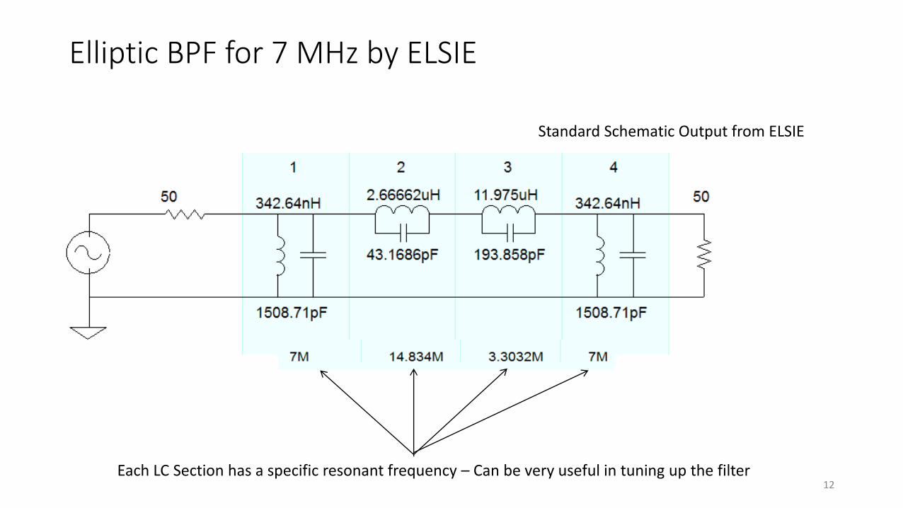
Elliptic BPF for 7 MHz by ELSIE
Each LC Section has a specific resonant frequency – Can be very useful in tuning up the filter
Standard Schematic Output from ELSIE
12
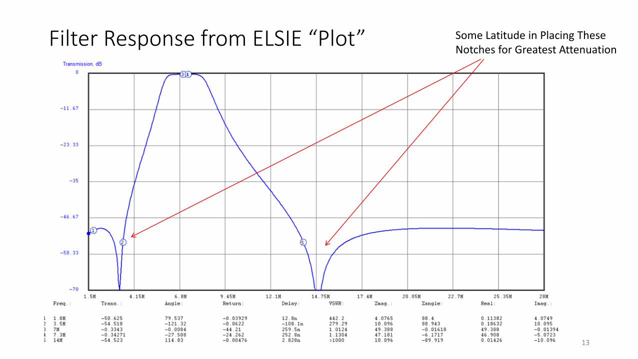
Filter Response from ELSIE “Plot” Some Latitude in Placing TheseNotches for Greatest Attenuation
13
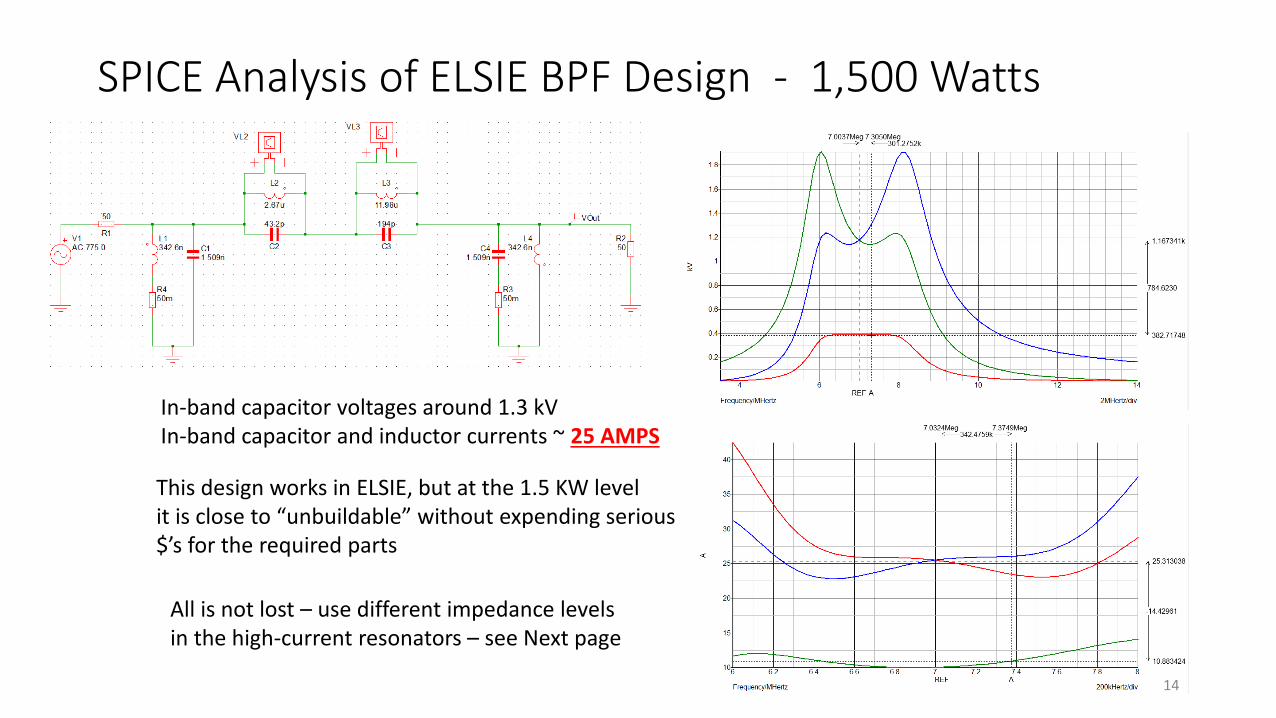
SPICE Analysis of ELSIE BPF Design - 1,500 Watts
In-band capacitor voltages around 1.3 kVIn-band capacitor and inductor currents ~ 25 AMPS
This design works in ELSIE, but at the 1.5 KW levelit is close to “unbuildable” without expending serious$’s for the required parts
All is not lost – use different impedance levelsin the high-current resonators – see Next page
14
A 16:1 Impedance Step-Up in First and Last Resonator Provides Current Reduction
• In 3 of the 4 cases where inductors are needed in my design, powdered iron toroids are used• Toroids are “self-shielding”, thus relatively insensitive to other nearby components
and aluminum/steel box walls• Use of single winding, air-core inductors become prohibitively large in the real estate
required. (This can be done, but capacitors complicate things)• Instead of using a single-winding on the first and last coils, use of quadrifilar windings
( four wires together) reduces the aforementioned 25 amps to 25/4 = 6.25 amps
• A source of good quality, low-cost, high-voltage capacitors is hard to find. When using air-core inductors, “door knob” capacitors are generally used -$20 each, or other high quality capacitors• These are expensive
• Multiple capacitors must be used in parallel to achieve “current sharing”
• I use MLCCs – multi-layer ceramic chip capacitors, which are very small and MUCH less expensive
15
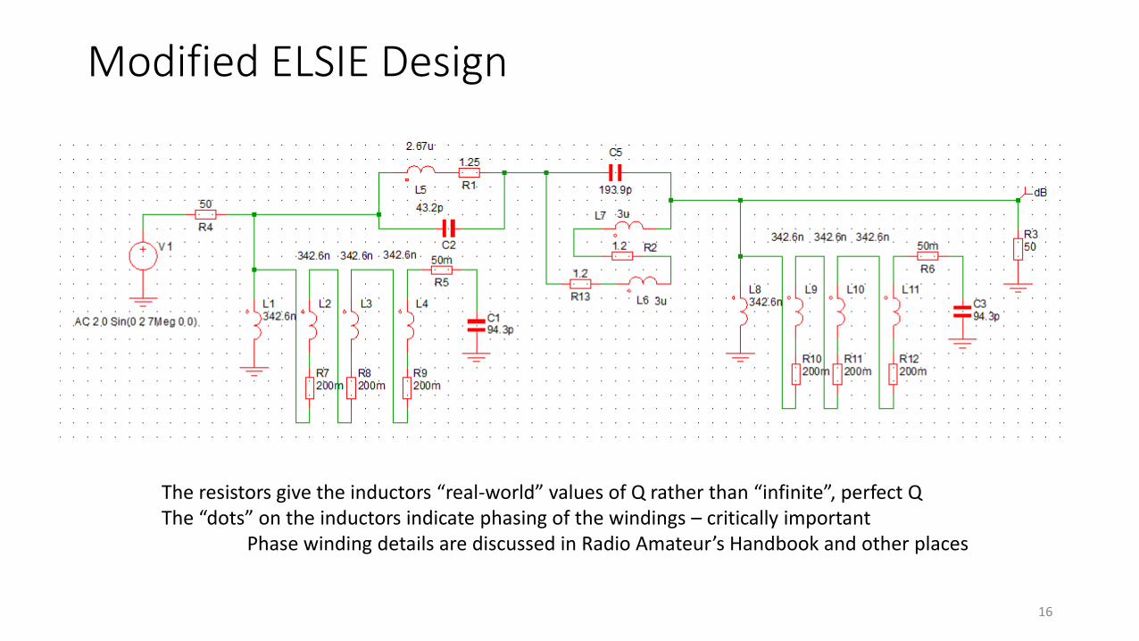
Modified ELSIE Design
The resistors give the inductors “real-world” values of Q rather than “infinite”, perfect QThe “dots” on the inductors indicate phasing of the windings – critically important
Phase winding details are discussed in Radio Amateur’s Handbook and other places
16
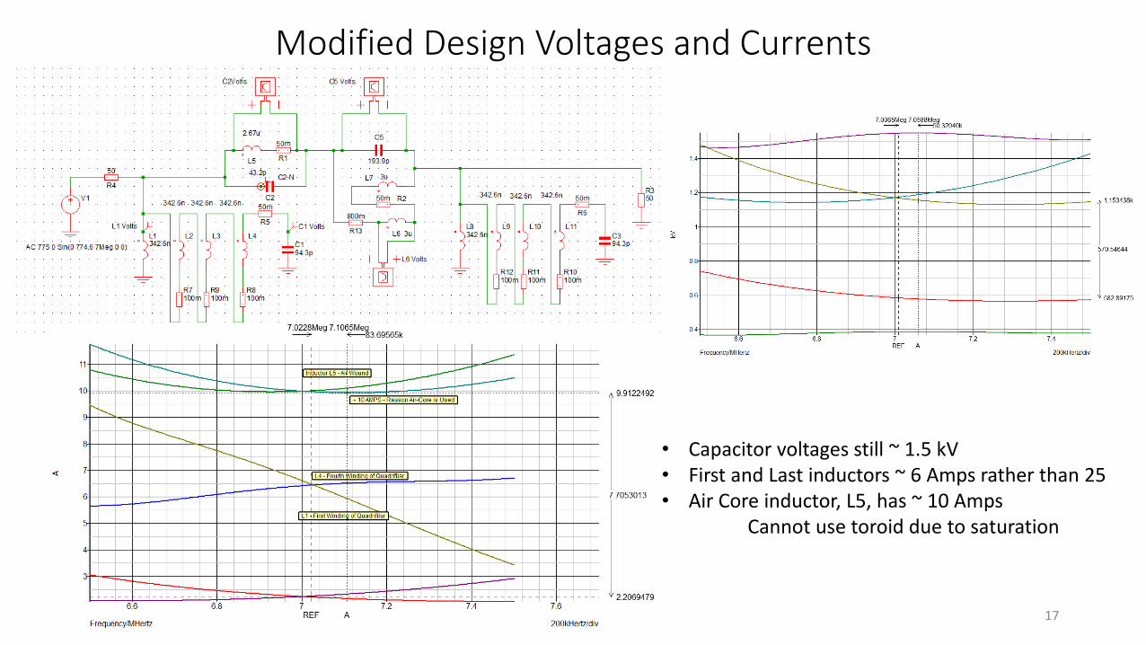
Modified Design Voltages and Currents
• Capacitor voltages still ~ 1.5 kV• First and Last inductors ~ 6 Amps rather than 25• Air Core inductor, L5, has ~ 10 Amps
Cannot use toroid due to saturation
17
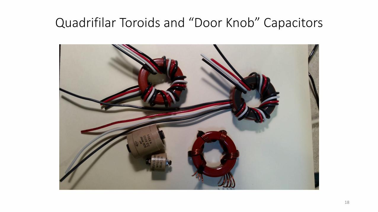
Quadrifilar Toroids and “Door Knob” Capacitors
18
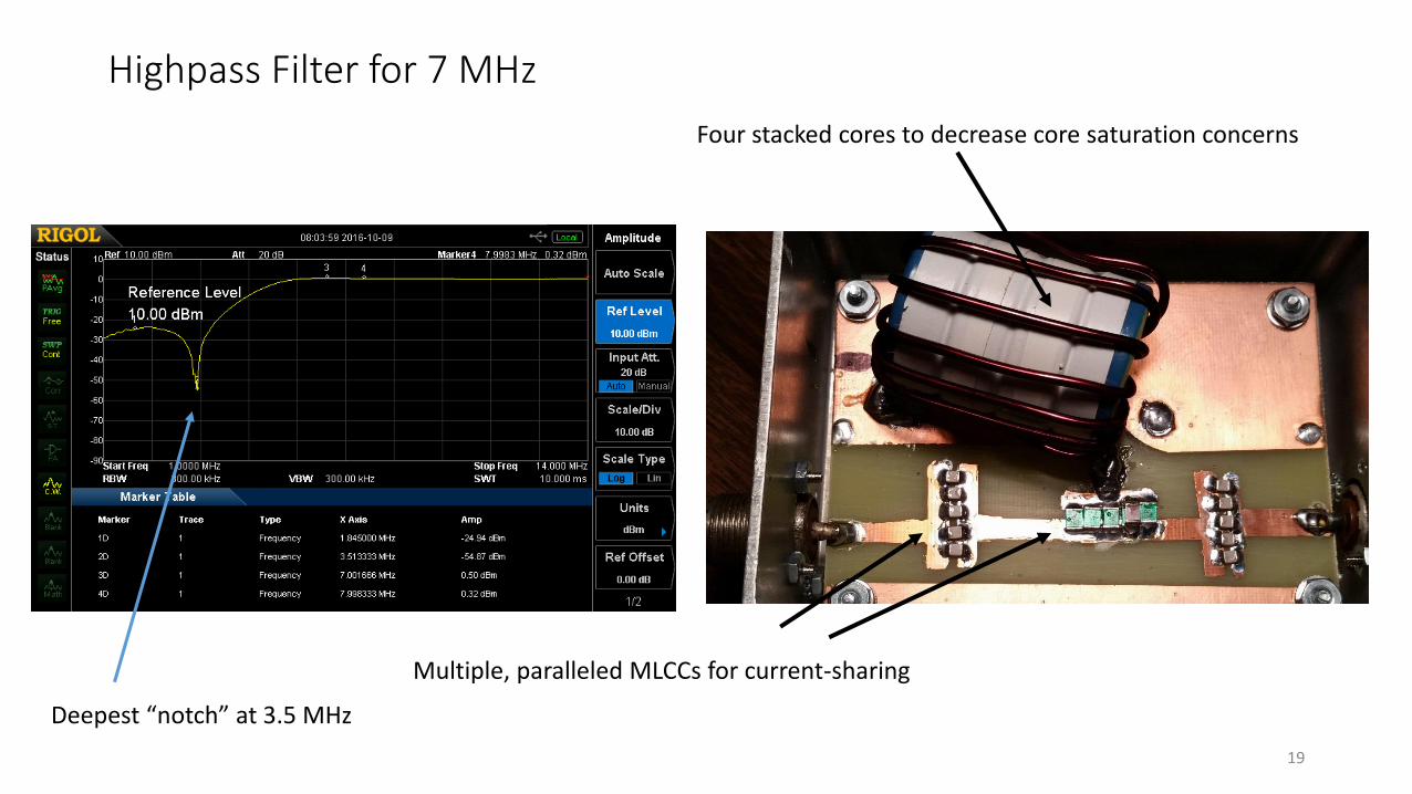
Highpass Filter for 7 MHz
19
Multiple, paralleled MLCCs for current-sharing
Four stacked cores to decrease core saturation concerns
Deepest “notch” at 3.5 MHz
Summary• High voltages and currents occur in even a 100 Watt filter, much less a 1.5 KW filter
• The nature of self-shielding in toroids makes the design more compact with less interaction from one resonator to the next• Must carefully monitor core saturation*
• When this occurs, use a larger diameter core or “stack” 2 or 3 cores together• In my case I elected to use a single, air-wound inductor for the one inductor
• Here we have considered only frequency response and out-of-band attenuation• In true “communications” applications, other factors such as group delay and linear phase must be
factored in
• Most filters we use are “Odd order”. Even-order filters have a different output impedance than their input, creating another VSWR challenge
• With the advent of inexpensive capacitance meters as well as other Z meters, such a project is doable without expensive test equipment. Once you “get close”, a LARG member with a network or impedance analyzer can get you across the finish line if needed.
20*Manner in which core saturation is calculated is found at Amidon Associates web site
Backup
21
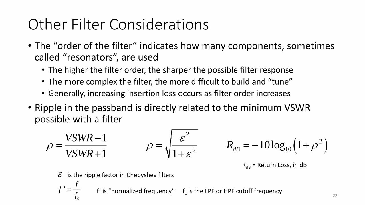
Other Filter Considerations• The “order of the filter” indicates how many components, sometimes
called “resonators”, are used• The higher the filter order, the sharper the possible filter response
• The more complex the filter, the more difficult to build and “tune”
• Generally, increasing insertion loss occurs as filter order increases
• Ripple in the passband is directly related to the minimum VSWR possible with a filter
2
2
102
110log 1
1 1dB
VSWRR
VSWR
is the ripple factor in Chebyshev filters
RdB = Return Loss, in dB
'c
ff
f f’ is “normalized frequency” fc is the LPF or HPF cutoff frequency
22