Embed Size (px)
Citation preview

al
--d
s
r
ation
the em-func-
tworkmentmpo-
reasinginstallt theywork
An Architecture for Building Scalable, Web-basedManagement Services
Nikolaos Anerousis
AT&T Labs Research180 Park Avenue, Bldg. 103
Florham Park, NJ 07932-0971tel: (973) 360-8767, fax: (973) 360-8871
e-mail: [email protected]://www.research.att.com/~nikos/
Abstract
We present the architecture ofMarvel, a distributed computing environment for building scal-able management services using intelligent agents and the world-wide web. Marvel is basedon an information model that generates computed views of management information and adistributed computing model that makes these views available to a variety of client applica-tions. Computed views consist of monitoring, control and event views of information collect-ed from network elements and subsequently aggregated using a series of spatial and temporfilters. Marvel does not replace existing element management agents but rather builds on topof them a hierarchy of servers that generate computed views and present them to client applications in a number of formats, including Java-enriched web pages. It uses a distributed persistent store to reduce the cost associated with centralized network management systems anmobile agent technology to a) support thin clients by uploading the necessary code to accesMarvel services and b) extend its functionality dynamically by downloading code that incor-porates new objects and services. A prototype implementation in Java is presented togethewith results from its first application on a residential broadband access system using cablemodems.
Keywords: Network management, web-based management, distributed computing, informaggregation, Marvel.
1. Introduction
In the recent years, one can observe a trend in the network management market that shiftsphasis from the underlying technology that the network management system employs to thetionality that the system provides. Finally people have come to agree that the choice of a nemanagement protocol (e.g. SNMP, CMIP or other) is only a minor detail in the overall manageframework. Rather, emphasis is now given on the system’s ease of integration with other conents, expandability, availability, ease of use (web-based management systems are incsteadily their presence), and reduced maintenance costs (including the time to train people,and configure software, etc.). A common pitfall of most management applications today is thastill operate at a very low level, many times exposing the details of communication with netelements using a low level management protocol.
1

sup-anag-g highon off net-tech-twork
vidingmple ofdition-er pre-ly lowe. Byay oflue thet system.creas-ws to
man-
ensiveices to
widelyith re-rovid-rovider
ed toerfor-
ded infor
, etc.at theent in-
nder-omer
In addition, networks are continuously shifting the traditional cost structure from hardware toport. Given this shift in investment, the emphasis in network management has moved from ming machines to managing services. Service-level management is necessary for providinlevels of service for mission-critical applications. Service management requires the definitihigher-level management services that monitor control the coordination of a large number owork elements. This paper explores how the combination of web and distributed computingnologies with an information model capable of expressing complex relationships between neelements can form the basis for designing and deploying complex management services.
1.1 The Emergence of Web Technologies
Java and the world wide web have received significant attention recently as a means of prolow cost and easy to use management services. Customer network management is an exaan application that has benefited significantly from the web-based management model. Traally, customer network management services have required the installation at the custommises of high-end network management applications such as HP Openview to access fairlevel management information using SNMP or log files that are copied and examined off-linincorporating this information into web pages, service providers have a more cost effective wproviding management services to their customers. Moreover, customers have come to vaeasy-to-use interface and the absence of a need to maintain a separate service managemenAnother very successful application of web technology has been element management. An ining amount of networking equipment is shipped today with an integrated web server that allomonitor and control the equipment from a web browser.
In general, web technology has a number of advantages that make it attractive for networkagement applications:
• The user of the management services is no longer required to install and configure expmanagement clients. Rather, the responsibility for converting managed objects and serva graphical form lies with the provider of these services.
• Services can be accessed by low cost client applications such as web browsers, that areavailable, and well understood by a large number of users. These clients are agnostic wspect to the structure of management information and nature of management services ped by the web-based system; all the necessary code and state are transferred from the pof the management services to the client.
• The information provided in a web-based form is usually at a much higher level compartraditional management services such as the ones provided by SNMP. For example, pmance information can be formatted into easy-to-understand graphs rather than provithe form of a log file that is processed off line. Similarly, control interfaces can be tailoreda particular application by providing a friendlier user interface, an integrated help systemIn reality, it is the provider of the management services that determines the interface thuser sees. This has many advantages: it prevents users from misinterpreting managemformation (the provider ensures that all information is presented in a user-friendly and ustandable form), and allows for bundling of other services (such as provisioning, custcare, etc.).
2

orma-.
ementhidingce, net-rator.tiator
rs ofwith ato ac-
travel-tables
y man-e sev-
differ-little
.
fromlay isstem.
inter-
iability
.g. thewidth
ementct thections.
t limi-at the
infor-ation
stem.k ele-
• Web-based information can be made to represent an up-to-date view of network state inftion, thereby improving the interactivity of the user with the network management system
Web technology requires a provider to define both the level of abstraction at which managinformation is presented and the graphical user interface to interact with these services. Bythe details of the underlying management technology under an easy to use and access interfawork management becomes a useful commodity rather than a privilege of the network opeToday, the bundling of management capabilities with a service is becoming a product differenof increasing importance.
The importance of web technologies in the future is justified by the speed with which vendonetwork management products are supplementing web-based interfaces. When enhancedweb-based interface, many conventional management applications allow network managerscess a managed system from low-end clients and troubleshoot problems while at home orling. Further, many routine data mining and performance reporting tasks that use charts andcan be better reproduced in a web-based form.
On the other hand, web technology has its limitations and cannot be used yet to replace everagement application, particularly the high-end network operation centers (NOCs). There areral reasons contributing to this fact:
1. Management systems for large networks require a large display area to project maps ofent logical views of the network. Even if the web-based interface is replicated, there issupport in current web technologies for coordinating individual displays with each other
2. Web interfaces require the client to retrieve large amounts of code and state informationa server. As a result, the rate at which information can be consumed by the client’s displimited compared to the capabilities of a traditional centralized network management sy
3. Web-based interfaces that are limited to HTTP interactions have a very restricted controlface with the server (hypertext links, post operations, CGI scripts, etc.)
4. Java-enriched interfaces are affected by the performance problems of Java and the relof its graphical user interface.
5. The Java security model does not allow clients (applets) to use some local resources (efile system, network connections to other servers, etc.), and as a result significant bandand computing resources are wasted in transferring information from and to the server.
6. Web interfaces require that an additional layer of processing be introduced in the managarchitecture to convert management information into a web-based form. This may impafreshness of information and the response time of the management system to control a
7. Finally, the power behind web-based management can sometimes be its most significantation: since management services and the way management information is presentedclient are defined at the server, there is no capability for the client to further process thismation to create, for example, more detailed management views or correlate the informwith other prior knowledge.
1.2 Information Models
Scalability is a major concern in the design and deployment of a network management syThere are no widely established methods today for dealing with large numbers of networ
3

essen-d eventusu-d in-
networkalablelly theinde-
earsstemscts toanage-an-t
tech-onven-ds forg is-
tworkfor in-ment
an bed invo-
ar-oyingution
nalityment
tionsr ownwever,rvices.
tion 4a pro-
ments. Managing large enterprise networks requires powerful abstractions that capture thetials of the state of the network rather than the details. Most approaches for reducing state aninformation in commercially available network management (NM) platforms are ad-hoc andally customized for a particular management problem or network. As networks grow larger antegrate an ever increasing number of components and services, the existence of a scalablemanagement architecture becomes critical. We believe that the key behind offering truly scmanagement services will be a new management information model that expresses naturamost common forms of aggregating network state. This model must further be application-pendent, to ensure that it can be applied to a variety of management problems.
The new information model will allow managers to “customize” the way that the network appto them for monitoring and control purposes, and will be key element behind management sythat scale as networks grow in size. The model that we propose provides high level construhide elements behind groups, define managed objects that represent computed views of mment information and provide higher level monitoring and control primitives, that allow the mager to interact with the network management system at theservicelevel as opposed to the elemenlevel that has been the common practice so far.
1.3 Marvel
The Marvel project at AT&T Labs Research is an attempt to investigate the limitations of webnology in network management and propose an architecture that can both scale and rival ctional management systems in terms of performance and expandability. Marvel (which stanManagement Aggregation and Visualization Environment) is trying to address the followinsues:
• Expand the web-based views of management information well beyond customer nemanagement and network element management applications. Marvel uses a frameworkformation aggregation that allows the dynamic construction of arbitrary views of manageinformation that can also be beneficial to network operators.
• Propose a distributed computing model for accessing management information that ceasily incorporated into web clients. Standards such as CORBA and Java remote methocation (RMI) [SUN97] are now widely accepted for network management applications. Mvel uses a distributed computing environment to reduce the cost related to deplcentralized hardware and software and at the same time hide all details of this distribfrom its users.
• Use concepts from intelligent agent and mobile code technology to enhance the functioof the web-based interface and improve the availability and maintainability of manageservices.
Marvel is not limited to the web-based interaction model. Rather, any type of client applicacan be built around its distributed computing services, from traditional applications using theigraphical interface, to server-driven management interfaces. The work presented here, hoemphasizes the features of Marvel that are central to providing web-based management se
This paper is organized as follows: Sections 2 and 3 present the architecture of Marvel; Secdescribes the current implementation work. Experiences from using the Marvel system on
4

ection
f net-ration ofire ac-ses anan ar-ele-
vidingcribed.
l con-nt pa-
ement-fromation ac-
plica-ware
y arets man-a. Ournd, forgement
in auted
duction network can be found in Section 5. Section 6 presents related work in the field, and S7 our conclusions and directions for further study.
2. Information Model
Management information in a large network today is usually distributed between the MIBs owork elements and, as a consequence, represents small aspects of the configuration or opethose elements rather than of the network as a whole. Management applications today requcess to a much higher level of management information and services. Our framework propoobject-oriented information model where the value of an object’s attribute can be defined asbitrary computation over other attribute values. The latter can be information residing insidement management agents or other computed attributes. The emphasis of our model is in proa technology-independent specification framework in which these computations can be desUsing this model, the network manager can define new managed objects that representcomputedviewsof management information. Computed views can represent a summary of lower levefiguration and performance information, or a more detailed view of a particular managemerameter.
Objects representing computed views of management information can be regarded as impling a “middleware management services” layer (Figure 1). This layer extracts informationmanaged elements using a standards-based management protocol, processes this inform
cording to the specification of the computed view and makes it available to management aptions through a distributed computing environment. Objects within the management middlelayer can follow the SNMP or OSI structure for management information (in which case theaccessed using the corresponding management protocol), or a proprietary format that exporagement services to a legacy distributed computing environment such as CORBA or Javmodel specifies only the way that an attribute value is computed from a set of components athis reason, it can be used as an extension to standards-based models for structuring manainformation such as SNMP SMI and GDMO [ISO91]. However, we believe that it fits betterdistributed computing environment such as CORBA [OMG93], since the notion of comp
Element Management Information
objects representing computed views
Management Applications
SNMP CMIP DMI
Distributed Computing Environment
Figure 1: 3-level architecture for generating computed views of management information
ManagementMiddleware
5

rvices
mationt and
t ser-
e oc-
ontrolgationhichhichvalue.
ber ofec. Foration
d intoxample,
suchcon-
etwork) pro-
specifi-mplex
group-are notdeptharchyA). A
ntain
views for network management is closely related to the notion of higher level management sethat can be implemented more efficiently in this framework.
2.1 Computed Views of Management Information
Computed views are constructed by applying an aggregation process to management inforcollected from network elements. Every computed view in our framework is stored in an objechas one or more of the following components:
1. A monitoring, view, which represents a higher-level view of network state,
2. a control view, which represents a control interface to higher-level network managemenvices,
3. an event view, which represents notifications that are generated by the object following thcurrence of a series of other (elementary) events.
The object’s attributes represent the network state that corresponds to the monitoring and cviews of the object. In order to define a new view, the network manager specifies an aggrerule with which every attribute value is computed. The rule can be specified declaratively, in wcase a description of the aggregation is provided in a structured language, or explicitly, in wcase the manager provides a piece of code that will be executed to compute the attribute’sAggregations can bespatial or temporal.
2.1.1 Spatial aggregations
Spatial aggregations attempt to reduce management information distributed between a numnetwork elements by presenting information aboutgroupsof elements. By defining the appropriatgroups, the manager can obtain a high-level view of network configuration, performance, etexample, the ingress traffic to a network region can be computed by processing traffic informcollected from switches at the border of the region.
In order to describe spatial aggregations efficiently, network elements (NEs) must be organizegroups. Users can dynamically define groups based on any factor that makes sense. For egroups can be formed according to geographical criteria (location) - a group of all NEs in a build-ing, campus, state, etc., or functionality (a group of all ATM switches), or some combinationas all ATM switches in New York City area. Groups can be defined easily through a networkfiguration database. In this case, group membership can be determined by identifying the nelements whose properties match a query predicate. The directory enabled networks (DENposal is an effort to standardize the schemata for such a configuration database. The DENcation also identifies the need to model network services and groups to support more comanagement functions.
It is easy to generalize and define groups with other groups as members. Thus, the networking hierarchy can be represented by a tree whose leaves are the network elements. Groupsnecessarily disjoint. Every group is characterized by a level indicator that corresponds to theof the tree where the particular group belongs. Level 0 is reserved for the leaves of a hierwhich (from a network management standpoint) represent element management agents (EMgroup at the first level corresponds to a set of EMAs. A group at the second level may cogroups of level one and perhaps one or more EMAs. In general, a group at leveln is allowed to
6

ment
2 and
2, andanageretwork
ork el-ber
ust berecur-s haveis pro-sent-
nents
rder toto an
ariousasure-
is as-the in-into a
contain groups of any level lower thann, i.e., leveln-1, n-2, ..., level 0 inclusive. Sometimes it isconvenient to refer to a group of level 0 which, however, really implies an element manageagent.
Figure 2 presents an example where network elements are first organized into groups G1, G
G3 that compose the first level of aggregation. Group G4 is defined as the union of G1 and Gsimilarly G5 as the union of G2 and G3. Once the group hierarchy has been specified, the mcan define higher-level management views and services by referring to groups rather than nelements. As the simplest example, assume that the attributeErrorCount is defined on someEMAs, representing the number of unrecognized packets arriving at the corresponding netwement. A new attributeErrorCount can be defined in a managed object to count the total numof errored packets received in the group G1. The latter can be computed by summing theError-
Count variables retrieved from every member of G1.
In general in order to compute the value of an attribute that refers to a group, the group mresolved to a set of agents that contain the required information. The resolution is performedsively in a number of steps equal to the order of the group. Once the information componentbeen identified, their values are retrieved and a new value for the attribute is computed. Thcedure is described in detail in Section 2.2. Similarly, control operations on an attribute repreing a group of leveln are mapped to a series of (elementary) control operations on the compoof the group.
2.1.2 Temporal aggregations
Temporal aggregations expose the time-varying properties of management information. In ocompute a temporal aggregation, information is collected periodically and provided as inputaggregation function. This procedure can be used, for example, to form a time series of vgranularities (minutes, hours, etc.) or, to provide an autocorrelation or cross-correlation mement.
2.2 Declarative specification of attributes
As mentioned previously, attributes may be specified declaratively. In this case, the attributesociated with a list of groups that determine the locations (management agents) that containformation necessary to calculate the attribute’s value. This list of groups is further expanded
Figure 2: Example for grouping network elements
G1
G2G3
G4
G5
7

se ob-lter
of thet as theexed
sticalical in-
p fromob-
e par-entents of
ample,
such
list of objects within these agents. When the appropriate attribute value from each one of thejects is retrieved, afilter functionis applied on the entire set to calculate the final value. The fifunction operates on the collected attribute values and stores the result as the current valueattribute. For example, the operation SUM adds all the retrieved values and stores the resulnew value of the attribute. The operation NULL stores all the retrieved values in an array indby each retrieved attribute. More complex filter functions may, for example, compute statiproperties such as the mean and standard deviation of a distributed data set, extract topologformation to generate a topology map, etc.
More formally, every attribute can be expressed by the following formula:
, (EQ 1)
wheref is the filter function,Gi is a group,ai is the component attribute’s name andoi is an objectselection predicate. The latter is used to select the managed objects (MOs) within the grouwhich information will be collected. Depending on the underlying management protocol, theject and attribute selection predicates may be specified in a different syntax to comply with thticular structure of management information (e.g., SNMP or CMIP) within an elemmanagement agent. Note that an attribute need not be computed exclusively from componthe same type.
Figure 3 demonstrates an example of the attribute value computation procedure. In this ex
the attribute valueV is computed from information components in groupsG1 andG2. First,G1 andG2 are resolved into a list of management agents. For each agent in groupG1, the object selectionpredicateo1 identifies the managed objects that contain the required information. From each
V f G1 o1 a,1
,( ) G2 o2 a,2
,( ) ... Gn on a,n
,( ), , ,{ }=
EMA or Marvel server
MOs
attr1, val1
attr2, val2
...
attrn, valn
Managed Object
G1
G2
Attribute value collection
objID attr_name attr_valV = f {(G1, o1, a1), (G2, o2, a2)}
Aggregated Expression:apply filter function
Figure 3: Computing an aggregated attribute value
8

dicatets ofd its
ol-f thisnition
an-
or ex-possi-s delta
n-e onepera-
nablingfromor ex-
al al-how
thatse,r con-for-ute’sof thevalue
de withf date.value,e man-ationsg its
ementCMIP.ntify, we
object, we obtain only the values of attributes that correspond to the attribute selection prea1. The groupG2 is processed similarly. The result of the collection process from all the agenG1 andG2 is stored in a temporary table that contains the origin of every attribute, its type anvalue. The table is then used as input to the filter function which calculates the new valueV.
Filter functions can be specified byreference, in which case the required code to process the clected attribute values is loaded dynamically from an external function directory. The benefit oapproach is that filter functions need not be integrated with the server, which allows the defiof new functions or the improvement of existing ones without disrupting the operation of the magement system.
Temporal aggregations of an attribute are accomplished by using special filter functions. Fample, a sliding window filter can store a collected attribute value as a time-series. It is alsoble to define new attributes using filter functions that operate on the stored time-series such afunctions, cross-correlation functions, etc.
For a settable attribute, there exists amapping functionthat describes how a value set by the maager will be propagated to the underlying components. The simplest mapping function is ththat distributes the same value to all of its component attributes. It can be used for control otions that require setting the same value to a group of devices, such as firmware upgrades, eor disabling features, etc. More complex mapping functions may use additional informationthe environment to determine the exact value that every component attribute must receive. Fample, in an ATM virtual private network (VPN), the manager may decide to increase its totlocated capacity by 10 Mbps. The mapping function in this case will determine the details ofthe new capacity will be distributed between individual virtual paths.
A refresh policyspecifies how an attribute value is computed: A synchronous policy impliesthe value is computed dynamically upon agetoperation on the attribute. In the asynchronous caan internal or external condition triggers the computation and storage of the value. The triggedition can be a time interval, in which case the value is computed periodically by “pulling” inmation from the component objects. It is also possible to link the computation of an attribvalue with the occurrence of an event. For example, an event could be an indication that onecomponent attributes has changed its value. An eager policy would recompute the attribute’seach time that any of its components change. The choice of the update condition must be magreat care: Infrequent updates introduce the danger that the computed information is out oOn the other hand, an eager policy may trigger very frequent computations of an attribute’ssome of which may not even be necessary (if the value is accessed at slower time scales). Thager sets the update condition taking into consideration the sensitivity of management applicthat use this information with regard to its accuracy and the complexity involved in computinvalue.
2.3 Accessing Element Management Agents through SNMP or CMIP
In many cases, a computed view is generated by collecting information from element managagents (EMAs) using a standards-based network management protocol such as SNMP orWhen attributes are specified declaratively, additional information is usually required to idewhich MIB objects inside the EMAs should be involved in the computation. For this reasonprovide mappings for both the SNMP and CMIP domains. The following rules apply:
9
d othermple,infor-
agented, and
tifierseries
object
pred-e base
whose
e by avantag-
ssoci-tabase.ndingg in-
cant-
G95,-model
iew ob-are gen-mposite
cer. Aninally, anon. Foramine
tf new
First, group definitions must always be resolved into a set of application-layer addresses anparameters of EMAs that represent the members of the group. In the SNMP domain, for exaevery EMA is represented by the combination of an IP address, a port number and securitymation such as community strings that may be required. In the OSI domain, every CMIPmust be described by an application layer address to which an association can be establishadditional security information.
For every SNMP agent within a group, the object selection predicate is a set of object iden(OIDs). If the OID corresponds to a column of a table, the entire column is retrieved using a sof get-next operations.
The OSI framework requires additional parameters to specify a target attribute, namely theclass, object instance, scope, filter and attribute name. Again, the groupG refers to a set of CMIPagents. The object selection predicate contains theobjectClassandobjectInstanceparameters tospecify the class and distinguishing name of a base object. In addition, a scoping and filteringicate further identifies a subtree of managed objects in the OSI containment tree rooted at thobject. The attribute selection predicate identifies the attributes within the selected objectsvalue will be retrieved.
2.4 Event Views
Traditionally, event filtering and generation of higher level (composite) events has been donseparate centralized event processing engine (usually an expert system). There are many ades in decentralizing the event filtering process:
• A higher degree of integration is achieved between the computed view and the events aated with the view. Most management systems today store events in a single event daNow, a computed view can store all events associated with the view inside the correspoobject and provide a customized event browsing/monitoring tool as part of its monitorinterface.
• A distributed architecture for event filtering and generation can be implemented at signifily less cost compared to configuring and installing centralized event filtering systems.
There has been a significant amount of work in the field of composite event generation [NYHAY96, MAN97]. Our event architecture uses the services ofREADY, an event processing and notification system [GRU97] to generate composite events. This section describes the overallfor producing and consuming events in our environment and the structure of event objects.
We distinguish between 4 entities: Event producers, consumers, clients and servers. Every vject can assume any or all of the above roles. Event producers are the sources where eventserated. These can be element management agents, or other view objects that generate coevents. An event consumer is an entity that has subscribed to receive events from a produevent server consumes events, processes them and stores the result in a local database. Fevent client contacts an event server and performs operations on the stored event informatiexample, event servers can be simple event log objects and clients browsing tools that exthese logs.
Events are defined using an object-oriented model. TheEventRootclass contains the attributes thaare common to all event classes. Further specialization from this class allows the definition o
10

ion:roduc-irec-
cationon of an the
nentsed. Theventsnts thatnsum-
t sup-
g theher at-
e oc-
takehich
gen-event
er at-class,.
pos-ratederingat the
al rep-event
.
lowingf bothlarge
types with additional attributes or functionality. The root class contains the following informatevent producer, type (class), timestamp, severity and data (in a list of attributes). The event per field indicates a network element known to the network configuration directory (the same dtory used to generate the groups of Section 2.1.1).
When an object acts as an event producer, it must register with a READY process a specifiof the composite event(s) that it is capable of generating. The latter is expressed as a functinumber of component events in the READY language and installed in the READY server wheproducer object is initialized. Then, the READY server collects all the required event compoand fires an instance of the composite event when all necessary conditions have been satisficomposite event is then sent to the corresponding view object for further distribution. Not all eproduced by an object need to be generated at an external READY server. For example, evecorrespond to state changes within the object are generated locally and then distributed to coers.
In order to specify an event generation condition in the READY language, the manager musply the following information:
1. The type (class) and severity of the event.
2. A time window during which the component events must have occurred,
3. The list of component events and a matching filter. The former are specified by supplyintype and source (producer object) of each event. The filter is a value assertion on the ottributes of the event.
4. An ordering condition for the events. The ordering condition may require that events havcurred in a certain order in order to be satisfied.
5. A trigger condition, which identifies when the computation to generate the event willplace. The trigger can be periodic (upon the expiration of a timer) or event-based, in wcase it is possible to trigger the computation upon the reception of a component event.
6. Rules that will be used to populate the data fields of the new event.
The filter of item 3) above allows to narrow down the events that will be used during the eventeration process. It is possible to filter by source (groups can also be used, in which case themust originate in one component of the group), severity, or an assertion on the event’s othtributes. By using an object-oriented model, it is also possible to filter events based on theirin which case, all descendents of the class in the event inheritance tree will satisfy the filter
The ordering condition can impose a partial or total order in which events have occurred. It issible to omit the ordering specification completely and simply indicate that the event is geneonly when all or one (or none) of the component events have occurred in any order. The ordcondition can also handle temporal repetitions of the same event (it is possible to require thcomponent event has happened a certain number of times within the time window), or spatietitions (the manager may indicate for example that a sufficient condition to generate the newis its occurrence in at least five elements of a particular group), or a combination of the two
The event model that we propose has a number of advantages. First, it is object-oriented, althe abstract specification of event type matching filters. Second, it allows the specification ospatial and temporal ordering conditions, a capability which has proven to be very useful in
11

tworkscal-
objecta num-sump-ent thefunc-91]de-gre-
etelygh theering-levelg dis-
oreRBAnded
virtualicallyevent
orma-y, etc.videdarately
w in a
a-en-
ssingagainstuld onlyt man-eds tople isperatorals. Theand
networks where events associated with element groups convey valuable information to nemanagers. Third, the distribution of the event filtering task between objects allows for a moreable filtering architecture.
2.5 Using a distributed computing environment
To summarize, computed views of management information are stored in objects. Everycontains a list of attributes that represent the monitoring and control views, and can generateber of notifications that represent the event view. So far, we have not made any particular astions about the management information model or the management protocol used to impleminformation aggregation architecture. In theory, it is possible to transparently implement thistionality within existing management modeling standards such as SNMP, CMIS GDMO [ISOor CIM [DMT98]. In CMIS for example, the attributes of the object may be accompanied by aclarative specification (Section 2.2) that will be used to implement the object’s information aggation functionality. Since this is related only to the object’s implementation, it can be compltransparent to the management protocol. Similarly, event views can be implemented throuCMIS event notification service. The implementation of the object is responsible for registwith all component events and performing the filtering procedure of Section 2.4. The higherevent is then generated as a CMIS notification and filtered through the CMIS event forwardincriminator layer.
However, the power of this information aggregation framework can be fully exploited when a mgeneric object services model is employed, such as the one provided by CORBA. The COframework allows the object to define an arbitrary set of services that complement the intemanagement function of the computed view. For example, if the computed view represents aprivate network service, the corresponding object may include higher-level services to dynammanage the allocated capacity of the VPN, retrieve graphs of usage information, configurenotifications whenever a particular usage pattern is observed, generate monthly billing inftion, provide predictions of service usage to help the manager provision for additional capacitIn contrast to the declarative specification of an attribute’s value, the additional services proby the computed view cannot be generalized. They must be specified and implemented sepfor every view. Some of these services may include functions that display the computed vieparticular graphical interface environment. Marvel uses the concept ofvisual domainsto representcomputed views in different graphical forms (conventional user interfaces such as Motif, Javhanced web pages, etc. - see Section 3.1).
2.6 Dynamic Query Processing
The realization of computed views and especially monitoring views requires substantial procepower, especially when they need to be updated frequently. For many years, the argumentcomputed views has been that they are needed quite infrequently and, by consequence, shobe computed on demand. It is not clear however that this approach is more efficient. Elemenagement agents usually store only dynamic information, and as a result, this information nebe transferred periodically to large data warehouses for off-line processing. A typical examthe generation of usage logs for customer network management services. The network ocollects usage statistics for every customer and generates a usage report at regular intervproblem with off-line computation is that the computed view can be significantly out of date,
12

e costbinedeighthe
in web-that pro-
s. OneFor ex-onth. Itce this. Forries inmputedt appli-
ure for
espe-ting
reduc-
vail-up-
ts of
ementt per-
jects,stom-man-
al as-sor
further, the needs for storing such information from a very large network can easily surpass thfor computing it on-line. We believe that processing power today is cheap, and when comwith a distributed computing environment, the advantages of on-line view computation outwthe cost. Not only can the physical location of view computation be completely hidden frommanager, but it can be enhanced with a server-driven graphical user interface, as is the casebased management systems. The result is an easy-to-use higher-level management servicevides significant added value to its users.
There are many cases however when the manager wishes to obtain highly customized viewcould regard those as the database equivalent of a query with unusual selection predicates.ample, one may wish to create a sorted table of customers spending more than $20 every mwould probably be inefficient to dedicate a separate object to represent the above quantity sintype of query may be encountered very infrequently, or with a different predicate every timethis reason, we intend to extend model with a query processing capability that receives quea structured language and generates transient objects that represent the appropriate coviews. The objects are deleted once the results of the query have been returned to the cliencation.
3. Computation Model
Every Marvel system is composed of a hierarchy of servers. We chose a distributed architectseveral reasons:
• Computed views of management information require significant processing resources,cially when they must be maintained continuously up-to-date. By distributing the computask, our architecture is more scalable.
• Computations can take place closer to the sources of management information, therebying the amount of management traffic to a centralized network management facility.
• A distributed architecture is more reliable since the failure of one server affects only the aability of information computed within that server. In addition, server maintenance andgrade tasks can be performed without affecting the operation of the entire system.
• And finally, a distributed architecture can be implemented by putting together componenlower cost and smaller footprint.
Every Marvel server stores its objects in a persistent store. Since computed views of managinformation usually include valuable historical data that cannot be easily reconstructed, objecsistence ensures the availability of this information through server failures.
Objects in Marvel provide two tiers of services: Basic Access, which are mandatory for all oband Extended that are implemented optionally. The latter can be used to provide a richer cuized interface to the object for performing more complex operations related to its intendedagement function. There are three types of basic services:
1. Attribute accessservices are used to set and retrieve attribute values and control severpects of every attribute’s operation. These functions includeget(retrieves an attribute value aan opaque object),set, action (dynamically downloads control logic that operates on onemore attributes or other objects), etc.
13

etupe bene-re tobjectmoreMar-
otifica-ggre-bject.
ndedes. Fors some
a settabase:
s con-e
in thee ob-does
r, ser-at theon theaded to
serv-ion inver thended, ine new
ORBAppli-uting
o Javample-a RMIppli-
2. Visualization services are used to provide clients with the necessary information to sgraphical user interfaces (GUIs) to access the object’s basic and extended services. Thfit of this approach is that clients do not need to be aware of an object’s internal structuprovide a user-friendly interface. In essence, the GUI is “programmed” as part of the oand is transferred to the client when it first accesses the object. The object may providethan one visualization services depending on the type of clients that are supported by thevel system (Section 3.1 contains a detailed description of the visualization model).
3. Event services are used to subscribe internal and external consumers to receive event ntions generated by the object, and control the event flow. Events in Marvel are usually agations of lower-level events corresponding to the management view portrayed by the oThe Marvel event system is described in detail in [YUC98].
A Marvel object designer is responsible for providing an implementation for all basic and exteservices. Access to the latter can sometimes be provided indirectly through the basic servicexample, the visualization functions can be overridden to set up a user interface that accesseof the object’s extended services.
In addition to the common services provided by every object, every Marvel server providesof high level services that can be used by client applications to navigate and examine the da
1. Navigation services are used to navigate through the server database and examine ittents. Current Marvel implementations store objects in a tree, and include functions likge-tRoot(retrieves the root object),getParent(retrieves the parent of an object),getSubordinates(retrieves the object’s children),getPath (retrieves the path from the root), etc.
2. Registration services are used to examine the structure and capabilities of every objectdatabase. In this way, clients can dynamically browse through the services provided by thject and invoke a service with the appropriate parameters. This introspection capabilitynot require clients to be previously aware of the services provided by every object. Rathevices are “discovered” in real-time and invoked after loading the appropriate stub codeclient. Objects must register themselves when they are created and provide informationattributes they contain, the extended services they support and the stubs that must be loinvoke these services.
3. Object managementservices are used to instantiate, upgrade or delete objects while theer is running. The manager provides the name of the object to be instantiated, its locatthe database and a pointer to the code that can be used to instantiate the object. The serdynamically loads the code and generates a new object instance. Objects can be upgrawhich case, the state of the object is frozen, the old code is purged from the agent, thcode is loaded and the captured state is passed to the new object.
The above services can be implemented using industry-standard platforms such as C[OMG93] and Java [SUN97] which are currently being used in many network management acations. Java’s remote method invocation (RMI) is a package that provides distributed compprimitives tightly integrated with the language, and is extremely easy to use and integrate intapplications. CORBA is a more widely accepted standard but requires more heavyweight imentations. Our intention is to provide the same object services under both frameworks: Javis more suitable for web (and other lightweight) clients, while CORBA for more demanding acations that require the widest possible interoperability.
14

r pro-el sys-o thevide.
ledgestan-
ode tovel ob-atinghe ca-
le ofobjectwouldta en-use di-ject’s
ccep-L is allows:
or,get, and
iewedof theichedo sim-nage-let (by
ontrolll the
. It isplet cantions
3.1 Object visualization model
Marvel does not rely on an existing standard to store management information or a particulatocol to access it. The architecture assumes that all interaction between a client and the Marvtem occurs at a very high level, provided by a user interface that is dynamically loaded intclient. The interface hides the details of how objects are defined and what services they pro
Marvel was designed under the assumption that the majority of its clients have no prior knowof the information stored in Marvel servers and the methods used to access it. Clients rely ondard features provided by the distributed computing platform to download the necessary cnavigate through the database and generate a graphical user interface to interact with Marjects. The Marvel framework requires that every object be able to “visualize” itself by genera user interface. In fact, there may be several ways of visualizing an object, depending on tpabilities of the client. For this reason, Marvel supports a small number ofvisual domains. For ev-ery supported domain, a Marvel object must implement a visualization function capabdisplaying the object in that domain. For example, a Gopher system would require that thebe converted into a textual representation before it can be displayed. A web-based systemrequire that every object be converted into an HTML page1, and any control actions for the objecbe implemented through HTML post operations and a CGI interface [MAS97]. Finally, a Javriched web browser can download Java applets to provide a more interactive interface andrectly distributed computing facilities such as CORBA and Java RMI to access the observices.
The latter visualization technique is of particular interest to our architecture due to the wide atance of the world wide web and Java. As a result, object conversion to Java-enriched HTMmandatory service that must be provided by every Marvel object. The technique works as fo
First, the client invokes the object’s toJeHTML() method in one of the following ways:
• by directly invoking the object’s method through the distributed computing environment,• by indirectly making an HTTPget request supplying the object’s name and address. The
request is then translated by the HTTP server to a call to the object’s toJeHTML() methodthe results are returned through the HTTP reply (Figure 4).
When the toJeHTML() method is called, the object generates an HTML page that can be vby the browser. It does so by generating a default layout for the page, on which the valuesattributes will be displayed. Then, each attribute is instructed to convert itself into a Java-enrHTML form. Simple data types such as strings and integers need only convert themselves intple text. More complex data types (especially the ones representing computed views of mament information such as tables and time-series graphs) may choose to invoke a Java appinserting the <applet> primitive). The same holds for attributes that represent the object’s ccapabilities. When the applet is used purely for monitoring purposes, it is possible to supply anecessary information inside the applet specification block through the <param> primitivealso possible to pass to the applet the name and address of the object, in which case the apinteract with the object directly. This is required for applets that need to perform control operaon the object, or to refresh the displayed information after the page has been loaded.
1. The Hypertext Markup Language (HTML) is the language used to format web pages [GRA97].
15

d thee always
ion ofgementvers thatlose tonience.t man-
ate viewsnerate
objectxter-serv-tity toough theIn thisess to
When the web browser encounters the <applet> block within the html page, it attempts to loaapplet’s code and any other Java classes needed for the applet’s operation. Java classes arloaded from an HTTP server.
3.2 Object distribution model
Marvel objects are distributed across a hierarchy of Marvel servers. The number and locatthese servers is determined by the system designer, taking into account the amount of manadata that needs to be processed, the storage and computing capacity of the servers, etc. Serperform frequent aggregation functions on management information should be located as cthe sources as possible. Servers are typically organized in a hierarchical structure for conveFor example, at the lowest level, there exist servers that process data collected from elemenagement agents using one of the standard management protocols. These servers can generthat correspond to the TMN subnetwork layer. A server at the level immediately above can gemanagement views for the network and service layer, etc. (Figure 5).
In order to make navigation easier through this hierarchy of databases and hide the details ofdistribution, Marvel uses a redirection primitive as part of the object navigation services. An enal configuration directory contains information about the hierarchy of Marvel servers. Everyer can determine its parent, siblings and descendants in the hierarchy by supplying its identhe configuration database. The server then creates pseudo-objects that, when accessed thrnavigation interface, return a pointer to the navigation service of the corresponding server.way, the manager is able to navigate through the hierarchy of Marvel servers and gain acc
Distributed Computing Environment: CORBA or Java RMI
Web Browser
<html><body>
<--attr1 appears as html text-->Customer Name=AT&T
<-- attr2 appears as applet --><applet codebase=/classescode=customercontrol.class ><param servername=”MarvelServ”><param object=”/Customers/att”></applet>
[ other attributes ... ]</body></html>
Generated HTML page
Marvel Server
HTTP daemonindirect object visualization request
call to toJeHTML()
object generatesa HTML page
for the object: /Customers/att
page is displayedin the browser andthe appletsare started
the appletcommunicateswith theobject directly
applet
The navigationpage makes arequest for anobject
Figure 4: Example of an indirect object visualization procedure through an HTTP server
Marvel database
16

thesea Unix
atures:
od In-
Javacus-Mar-amic
their objects without knowing the details of the hierarchy or address or physical location ofservers. Navigation in this distributed database resembles very much the navigation throughfile system with NFS mount points.
4. Marvel Implementation
We selected Java to implement the Marvel architecture because it has a number of useful fe
• Distributed object services are well integrated with the language (the Java Remote Methvocation - RMI package).
• Ability to load and execute code dynamically.• Graphical User Interfaces are a core part of the language.• Compile once - run everywhere capability.• Is supported from practically every computer on the Internet with a Web browser.
In the current implementation, Marvel clients are web browsers with the capability to runcode. In future implementations, we expect a wide variety of clients, from text based tools totomized applications that make more efficient use of the distributed computing environment.vel servers are fully implemented in Java to take advantage of code portability and dynexecution features of the language.
Level 0(element agents)
Level 1
Level 2
network server
Subnetwork A
Subnetwork B
Subnetwork C
Figure 5: Example of Marvel server distribution
server forsubnetwork A
server forsubnetwork B
server forsubnetwork C
Mar
vel S
erve
rs
17
ides ad API
Everyple-
r. Ob-. The
ntain-ariza-cts thatntifierabaserator,
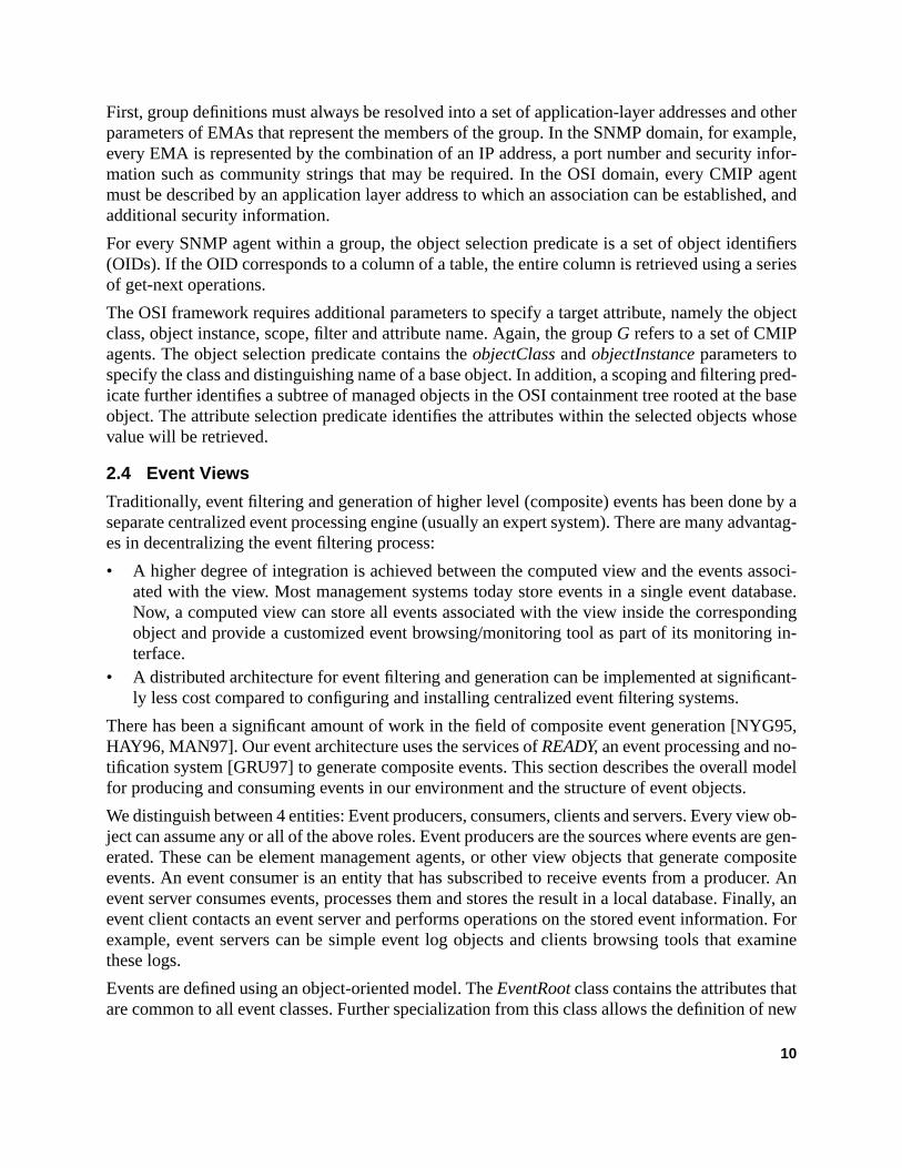
4.1 The Marvel server
Every Marvel server is composed of a collection of subsystems (Figure 6). This section provgeneral description of each subsystem. We have omitted most implementation details anspecifications due to lack of space.
Marvel objects are defined directly in Java and are stored in a persistent database [ODI97].object is derived (inherited) from a generic Marvel object class that provides a template for immenting the object’s basic and extended services, and a facility for registering with the serveject services are currently implemented using the Java remote method invocation API
database is implemented as a tree of objects. It is usually convenient to follow a natural coment relationship for placing objects in the tree. For example, an object representing a summtion of performance parameters from a set of users could be placed as the parent of the objecontain performance parameters for individual users. Every object has a unique string ide(the name of the object) that distinguishes it from its siblings. Path names in the Marvel datare constructed by following a path from the root to the object and using ‘/’ as the path sepa
Java RMI access interface
Protocol Modules
EventServices
to other servers and client applications
SNMP CMIP Java RMI CORBA
element agents or other Marvel servers
Figure 6: Server block diagram
Marvel
Persistent Storage Database
HTTPServer
Web Browser
Aggregation Processing
Query Processing ObjectRegistry
toJeHTML()
navi
gatio
n
HTML pagesJava Classes
Con
figur
atio
nD
irect
ory objects
DMI
18

“att”ted as
ility to
lementthese
everynd aretion ofed ser-y func-l partported
sponsi-e ob-hichn pro-
(thecode,y dur-n rep-erversementscess] to
P re-e re-ultinghese
spon-nsum-mes aual fil-g moreresentiffer-ssingcts that
exactly as in the Unix file system. For example “/Customers/att” refers to an object namedlocated under a container object called “Customers”. Each one of these objects is implemena Java class inheriting from a common parent. Each object implementation has the capabinitialize threads that can be used for background computations, event generation, etc.
A set of basic attribute classes are also included in the Marvel core class package, to impsimple data types, tables and time series. More complex data types can be easily derived frombase classes. The constructor function for every object class is responsible for instantiatingattribute. An important property of the Marvel system is that attributes are also Java objects atherefore permitted to export their own service interfaces. Therefore, the designer has the opimplementing attribute-specific services as a complement to the object’s basic and extendvices. When the attribute class library needs to be augmented with a new data type, a displation must also be provided for the new attribute. In this way visualization becomes an integraof data type definition, and so, client applications need not be aware of the data types supwithin each server since the appropriate viewer/controller will be loaded automatically.
Operating closely with the database is the aggregation processing engine. This engine is reble for computing every object’s attribute values. Value computations can either be manual (thject programmer is responsible for collecting the necessary information, or automatic (in wcase the attribute’s declarative specification is used. In the latter case, the value computatioceeds as in Section 2.2.
An external configuration directory is used to store information about the entire Marvel systemhierarchy of servers, group definitions used in attribute specifications, dynamically loadedetc.). The directory is the only centralized piece of our architecture and is consulted frequentling the operation of each server. We have chosen a centralized directory to avoid informatiolication issues between the servers, since the configuration information is not static: Marvel scan be added into the system at any time, group definitions can change to incorporate new elin the network, etc. Currently, we are using an X.500 directory with LDAP as the directory acprotocol. We are following closely the directory enabled networks (DEN) initiative [JUD98eventually align the Marvel directory architecture with this work.
An HTTP server is integrated in the Marvel server for performance reasons. Incoming HTTquests for Marvel objects are converted into a call to the object’s toJeHTML() function and thsult is printed directly to the HTTP response stream. This technique does not buffer the resHTML text (as is the case for CGI and fast-CGI calls) and allows for very fast rendering of tpages in the browser.
Two additional modules are currently under development: The event processing module is resible for aggregating lower-level events, generating event notifications, registering event coers and creating event channels over which events are transmitted [YUC98]. Also, many timanager may wish to generate a computed view of management information using an unustering predicate. For example, one may wish to create a sorted table of customers spendinthan $20 every month. It would probably be inefficient to dedicate a separate object to repthe above quantity since this type of query may be encountered very infrequently, or with a dent predicate every time. For this reason, the Marvel architecture allows for a query procemodule. This module receives queries in a structured language and generates transient obje
19

e query
-sidee cur-
st pop-tarts alizationI.
s withtools.
a lossrtu-serversstom-grad-
t side,w man-
ice in-
twork.thatuses atraffiche up-
whichpportsn engi-
severalefit fromtions.ervedvel 1. At
cs for
represent the appropriate computed views. The objects are deleted once the results of thhave been returned to the client application.
4.2 The Marvel client
The minimum requirement for a Marvel client is a bootstrap capability that loads the clientcode from a Marvel server. The bootstrap code will then enable access to Marvel services. Thrent architecture favors clients that support display of HTML pages and Java, such as the moular web browsers. Every server maintains a “home page” which, when loaded by a client, snavigation applet that is used to examine the server’s database and invoke an object’s visuafunction. More demanding applications can access directly Marvel services using Java RM
4.3 Benefits of Intelligent Agent Technology
The use of intelligent agent technology allows to offer complex network management servicea much smaller client footprint compared to traditional network and systems managementOn the other hand, pushing more functionality within the Marvel servers has not resulted inof flexibility or efficiency: The capability to load new server-side code offers many new opponities for network management, such as the ability to delegate management tasks to manyand coordinate their execution to achieve dynamic and parallel computations, the ability to cuize and configure existing services in real time either by introducing service adaptors or by uping the existing service logic, and the ability to decentralize management tasks. At the clienthe server-launched applets allow the users of the management system to access instantly neagement services and information and interact in real-time with complex data types and servterfaces.
5. Marvel Applications
5.1 The SAIL network
We are currently using the Marvel system to manage the SAIL experimental home access neSAIL (Speedy Asymmetric Internet Link) is an AT&T Labs broadband home access trialbrings a 10 Mbps data channel to users homes through a downstream CATV channel, and28.8 modem for the return path. Sail consists of a head-end router which multiplexes all useron the CATV channel a terminal server, and cable modems (one per user) that terminate tstream and downstream channels and route the collected packets onto a local Ethernet onthe user has connected a number of PCs or workstations. The SAIL network currently suabout 150 users and will grow to about 400. The home access architecture however has beeneered to handle many cable distribution head-ends, each one of them providing service forhundred users. Home access networks have exactly the large scale properties that can benthe Marvel architecture to provide summarizations of performance data and bulk control acThe architecture is shown in Figure 7. We use one Marvel server for every group of users sby the same cable operator (i.e. that share the same head-end). These servers operate at lethe second level of the hierarchy, another Marvel server provides global monitoring statistithe entire Sail network.
20

causeg sys-em. Intrans-
g soft-ingleystemrmancecurrent
es off-s inter-
viewsm the
s. Everyther withates inplays a
ut 50levelins ag-ort in-times
Summarizing performance such as bandwidth usage in this environment is very attractive benot only does it give statistics for larger sets of the user population, but also helps in plannintem capacity and the number of served users at every branch of the cable distribution systaddition measuring the error rates for different groups of users can help to identify areas withmission problems and sometimes pinpoint the location of the problem.
In terms of control operations, cable modems occasionally require updates in their operatinware. Marvel is also valuable in this case since it is able to perform this distribution with a scontrol action on a group that represents the entire network. We have found that the Marvel shas many advantages over commercial network management applications because perfoaggregations can be stored and accessed at any time. In order to do so when using one of thecommercial network management tools, a new application needs to be written that accessline the centrally collected data from the cable modems using a proprietary database accesface.
In addition to the above performance summarization features we also support customerthrough objects that represent “user profiles”. These objects combine account information frouser registration database with per-user temporally aggregated performance measurementsuch object generates a web page that a user can access to view his/her account status togea time series of their bandwidth usage and observed quality of service (transmission error rthe downstream channel). Time series are visualized using a special Java applet that dischart and allows scrolling and zooming for more careful examination of the data.
In the current architecture, we use one Marvel server for every CATV distribution tree (abomodems). The server periodically obtains information from the cable modems through a lowmonitoring and control protocol and updates the appropriate objects. A separate object contagregated performance information for the group and also a table attribute which is used to sdividual user information based on usage or error rates. Finally, a time-line chart indicates the
home ethernet
cablemodem
CustomerDatabase
Terminal Server
cablemodem
cable distribution
Head EndRouter
Figure 7: Managing the SAIL Network
PSTN
Head EndMarvel server
...
level 1
Marvel server level 2
Web Clients
21

quicklyeconds soft-
97. Itnvert-rfor-) and
rol ofouters)objects
arvelttribute’s Java
reted. Thesen-timeccess
that every user has been active (see Figure 8). These two attributes can be used to identifyusers with high usage or error rates or online activity as well as compare individual users. A slevel server contains performance and control aggregations for the entire network and allowware distribution to the entire set of cable modems.
5.2 Experiences with the SAIL management system
The Marvel system was deployed to manage the production SAIL network in September 19replaced an older web-based system which polled cable modems for error information and coed the data into HTML pages for every user once a day. Marvel allows browsing through pemance data with better granularity (data collection from the network occurs every five minutesfreshness (all information is at most 5 minutes old). It further integrates monitoring and contcomponents from different manufacturers (cable modems, terminal servers and head-end runder one user interface. The amount of code needed in order to implement new managedwas also better than expected: excluding the code needed to collect data from EMAs, every Mobject requires on the average about 3-4 lines of Java code per attribute. Constructing new adisplay applets proved to be equally easy when using a Java GUI builder tool such as SunWorkshop.
The only limitation we have found with the current system is performance. Java is an interplanguage, and a noticeable delay is introduced when pages with many applets are displayedperformance problems are expected to disappear in the future with the use of improved just-i(JIT) compilers. Another issue that we are currently investigating is how to enforce security a
Figure 8: A snapshot of the cable tree group object
22

omersan au-mation
apa-erest,. Anrans-notifyserver
ber ofilities
ithineroge-s in 4level
ssity ofscale
ects of
de-ups invers inolicy)e theation
ns. Theanage-on the
ement
eed toment in-ll arith-is alsoons.
control on the Marvel database. Especially for customer management applications, custshould not be allowed to look into each other’s data, and for this reason we are developingthentication procedure that supplies clients with the necessary credentials to access inforstored in Marvel.
When the event subsystem is fully integrated with Marvel, the SAIL operator will have the cbility of browsing through large numbers of event types, subscribing to receive events of intand linking incoming notifications with audio-visual effects in applets running inside the clientevent log browsing facility is also provided for examining detailed event traces that are not tmitted to the client. Of particular interest to the SAIL management system are events thatthe operator of unusual high error rates at a customer’s premise, high utilization at a terminalsite, and individual customer activity.
6. Related Work
The need for aggregations in order to manage large networks has been identified in a numprevious works in this field. One of the most organized efforts to provide management capabfor large networks is the Telecommunications Network Management (TMN) working group wthe ITU. The TMN standards have been developed to ensure interoperability between hetneous networking equipment and to provide a conceptual layering of administration functionlevels: the network element level, the network level, the service level and the business[ITU91].
At the same time, network management researchers have started to acknowledge the neceintroducing new abstraction mechanisms in network management to cope with issues of[TAK95]. There have been several pieces of work in this area addressing one or more aspthe problem:
Domains[SLO89] was the first framework to explore division of management responsibility byfining groups of managed objects on which a common management policy is applied. GroMarvel do not represent managed objects but rather collections of network elements and serwhich managed objects are stored. Marvel assumes that if a new view (or management pneeds to be defined on a collection of objects, it will be provided by a new object and hencconcept of grouping is used only as a means of reference from the new object to its informcomponents.
[STA96] presents a language that can be used to provide high-level management abstractiolanguage can be used to define the mapping between abstract models and the underlying mment information provided by agents and management platforms. The language is basedOSI GDMO, and for this reason is specific to GDMO-defined object classes for basic managinformation [ISO91].
[KAL96] presents a special agent proxy that acts as a front end for one or more nodes that nbe managed as a group. It uses a spreadsheet paradigm to process the underlying manageformation and provide a table of computed attributes. The spreadsheet language supports ametic, logical and relational operators. Except from computed attributes, the spreadsheetcapable of generating event reports by evaluating predicates containing relational expressi
23

anSQL.
ack of
e di-of in-8 baselication-struc-ws forme-e in-during
mmonhe de-tory.
ntedays in
d in-
ks wasriptscantly. Moreogy as
man-h the
nt canurc-Java.
tfinitytworkologies
tions.
softllowsJMAPI,roto-port for
e-nt so-
[GOL96] proposes extensions to the SNMP-SMI that allow the creation of MIB views withinagent. Views are created by defining operations on SNMP tables using a language similar toSupported operations include joins, filtering, table snapshots, etc. However, the main drawbthis approach is that views are restricted to the information contained in one MIB only.
The most coordinated effort in the area of network configuration directories is the one from threctory enabled networks (DEN) group. The DEN proposal [JUD98] integrates the storageformation about network components, services and users in an X.500 directory. It definesclasses and an extensible schema based on inheritance and aggregation for modeling appspecific properties and information. The information model allows to describe both the staticture and temporal relationships (behavior) of network elements and services, and further allothe definition of groups. We believe that the DEN effort will provide an excellent support frawork for the work presented in the paper. The definition of the group hierarchy required by thformation model that we have presented here can be stored into this directory and accessedthe execution of data aggregation functions. In addition, the directory can be used to store coaggregation function definitions together with their executable code. One could also control tclarative specification of an attribute representing an aggregated quantity through the direc
Finally, CIM [DMT98] aspires to define a common information model based on object-orieconstructs that can be used across management applications. We are currently exploring wwhich CIM can be expanded with features from our information model to provide automateformation aggregation functionality.
The idea of loading code into a management agent to perform locally some management tasproposed for the first time in [YEM91]. The initial approach was to download management scthat were compiled and executed at the agent. The arrival of Java has made this task signifisimpler, and also allows the reverse operation (code downloaded from the agent to the client)recently, many researchers are investigating the benefits of intelligent/mobile agent technola more generic framework for performing distributed management tasks [MAG96, BAL97].
In the visualization area, [CRU93] first proposed an immersive environment that enables theager to navigate through the network state and perform high level control operations througexchange and processing of multimedia information. Early work on Web-based managemebe found in [BAR97] and [REE97]. The first presents an HTTP proxy to SNMP and CMIP resoes and further describes a framework for remote execution of management tasks written inThe latter describes the implementation of a Web-based management console for the IBM NePC management application. [MAS97] highlights the advantages of using the Web as a nemanagement tool and presents the advantages and disadvantages of different Web techn(CGI scripts, HTML forms and Java) in element, network and service management applica
Parallel to our work is the development of the Java Management API (JMAPI) toolkit from Sun[SUN96]. JMAPI builds on the idea of downloading Java byte code to web browsers that athem to access server-defined management services. Marvel has several advantages overnamely the capability to define automatically computed views of management information, pcol adapters to a large variety of managed elements, a unified object naming space, and supa large variety of thin clients.
Similar in functionality to JMAPI is the WBEM project [THO98]. WBEM relies on the HyperMdia Management Protocol (HMMP) to access management information, allowing manageme
24

tailed
rvices.that
e viewclients
h any-stan-ationsisualuting
givenel dis-ppro-
viewity, cli-ce therates
ss toomingstepticallyvidingpplica-
enefitpt of
es ap-
rovid-e inter-ingementnt thatds com-s ofage-
egrat-
lutions to be platform independent and physically distributed across an enterprise. A more desurvey of web technologies for network management can be found in [HON98].
7. Conclusions and future work
Marvel is a framework that enables the development of scalable network management seScalability is achieved by a) supporting computed views of low level management informationconvey the essence of the network operating state rather than the details, b) distributing thcomputation task to a hierarchy of processors (servers) and, c) supporting large numbers ofthereby allowing ubiquitous access to network management information.
Marvel objects represent aggregations of management information which is obtained througcombination of standard management protocols such as SNMP, CMIP, DMI or any other nondard solution. The manager is responsible for specifying the policy with which these aggregare computed. Information stored in Marvel objects is then made available in a variety of vforms using the concept of visual domains and object self-visualization. A distributed compenvironment such as Java RMI or CORBA provides remote object access services. We haveparticular attention to the web visual interface; web browsers can navigate through the Marvtributed database and visualize objects of arbitrary complexity by dynamically loading the apriate viewers/controllers.
The SAIL broadband home access network is currently serving as the platform for testing thecomputation framework and evaluating several aspects of the Marvel system such as securent/server interaction performance, etc. Work is also under way to add event support, enhanattribute library with additional data types and design an improved user interface that integdata mining with event notification capabilities.
Leveraging from the popularity of the web, we achieved our goal of providing simple accecomplex management services. The quality of bundled network management services is becan important differentiator for many telecommunication service offerings and Marvel is onetowards achieving this goal. Marvel clients can be as simple as web browsers, which dramareduces the footprint (and cost) associated with the client, and makes Marvel suitable for proa wide range of management services, from enterprise to customer network management ations. Given that web technologies are evolving at a very rapid pace, Marvel will be able to bin the future from technologies such as XML (the Extensible Markup Language). The concevisual domains, allows Marvel to incorporate such new functionality as these new technologipear.
In addition, we demonstrated that standards based management is not the only solution for ping comprehensive management services. Marvel demonstrated that data types and servicfacesneed not be standardizedto perform network or system management functions. Rather, usintelligent agent technology, Marvel clients download the appropriate code to access managservices on demand. Marvel follows an important trend in contemporary network managemeplaces more emphasis on the functionality perceived by the end-user, as opposed to standarpliance in every level of the architecture. In fact, compatibility with standards is only a meanensuring interfacing with managed elements, not an indicator of quality for the offered manment services. Of course, interoperability issues are critical, especially for the purpose of int
25

te inMar-
vid-
de
ol-
et-
ca-
, in
forp-
alehop,
EEE
re ofIn-
ge-
and
sign
ing Marvel with other management systems, and for this reason it is worthwhile to investigathe future how information aggregations and higher level management services provided byvel can be potentially standardized.
Acknowledgments
The author would like to thank Alexandros Biliris, HV Jagadish and Chuck Kalmanek for proing their valuable feedback throughout the design of Marvel.
References
[BAL97] M. Baldi, S. Gai and G.P. Pico, “Exploiting Code Mobility in Decentralized anFlexible Network Management”,Proceedings of the First Intl. Workshop on MobilAgents, Berlin, Germany, April 1997.
[BAR97] F. Barillaud, L. Deri and M. Feridun, “Network Management using Internet Technogies”, in Proceedings of the 1997 IEEE Integrated Management, San Diego, CA,1997.
[CRU93] L. Crutcher and A.A. Lazar, “Management and Control for Giant Gigabit Nworks”, IEEE Network Magazine, vol. 7, no. 6, pp. 62-71, November 1993.
[DMT98] Desktop Management Task Force, “Common Information Model (CIM) Specifition Version 2.0”, March 1998.
[GOL96] German Goldszmidt, “Network Management Views using Delegated Agents”Proceedings of the 6th IBM/CAS Conference, Toronto, Canada, November 1996.
[GRA97] I.S. Graham, “HTML Sourcebook”, John Wiley and Sons, 1997.[GRU97] R.E. Gruber, B. Krishanmurthy, E. Panagos, “READY: A Notification service
ATLAS”, AT&T Labs Technical Memorandum HA6163000-970905-07TM, Setember 1997.
[HAY96] R. Hayton, J. Bacon, J. Bates and K. Moody, “Using Events to Build Large ScDistributed Applications”, in Proceedings of the 1996 SIGOPS European WorksConnemara, Ireland, Sept. 1996.
[HON97] J. Hong et. el., “Web-based Intranet Services and Network Management”, ICommunications Magazine, October 1997.
[ISO91] Information Processing Systems - Open Systems Interconnection, “StructuManagement Information - Part 1: Management Information Model”, July 1991.ternational Standard 10165-1.
[ITU91] ITU-T Recommendation M.3010, “Principles for a Telecommunication Manament Network”, Geneva, November 1991.
[JUD98] S. Judd and J. Strassner, “Directory-enabled Networks - Information ModelBase Schema”, preliminary draft, February 1998.
[KAL96] Pramod Kalyanasundaram, Adarshpal S. Sethi and Christopher M. Sherwin, “Deof a Spreadsheet Paradigm for Network Management”, inProceedings of the 1996DSOM: Distributed Systems Operations and Management, L’ Aquila, Italy, October28-30, 1996.
26

ch-
n-ring
ge-
nte-
tp://
and
n the
ort-
m/
//ja-
of
mu-
in-107,
De-TR/
et-
[MAG96] T. Magedanz, K. Rothermel and S. Krause, “Intelligent Agents: An Emerging Tenology for Next Generation Telecommunications?”, inProceedings of the 1996 IN-FOCOM, San Francisco, CA, 1996.
[MAN97] M. Mansouri-Samani and M. Sloman, “GEM, A Generalized Event Monitoring Laguage for Distributed Systems”, IEE/BCS/IOP Distributed Systems EngineeJournal, 4:2, June 1997, pp 96-108.
[MAS97] M.C. Maston, “Using the World Wide Web and Java for Network Service Manament”, in Proceedings of the 1997 IEEE Integrated Management, San Diego, CA,1997.
[NYG95] N.Y. Nygate, “Event Correlation using Rule and Object Based Techniques”, in Igrated Network Management IV, Chapman and Hall, 1995.
[ODI97] Object Design Inc., “Objectstore Persistent Storage Engine for Java”, URL: htwww.odi.com/content/products/pse/doc_120/doc/index.html.
[OMG93] Object Management Group, “The Common Object Request Broker ArchitectureSpecification”, Rev. 1.2, Dec. 1993.
[REE97] B. Reed, M. Peercy and E. Robinson, “Distributed Systems Management oWeb”, in Proceedings of the 1997 IEEE Integrated Management, San Diego, CA,1997.
[SLO89] M. Sloman and J. Moffett, “Domain Management for Distributed systems”, inInte-grated Management I, pp. 505-516, North Holland, 1989.
[STA96] Michael Stadler, “Mapping Management Information to Service Interfaces Supping High-Level Network Management Applications”,Proceedings of the 1996DSOM: Distributed Systems Operations and Management, L’ Aquila, Italy, October28-30, 1996.
[SUN97] Sun Microsystems Corporation, “Java RMI Specification”, ftp://ftp.javasoft.codocs/jdk1.1/rmi-spec.pdf.
[SUN96] Sun Microsystems Corporation, “Java Management API Architecture”, http:va.sun.com/products/JavaManagement/.
[TAK95] Makoto Takano and Katsumi Fujita, “Multilevel Network Management by meansSystem Identification”, in “Proceedings of the 1995 INFOCOM”, pp. 538-545, Bos-ton MA, April 1995.
[THO98] J.P. Thompson, “Web-Based Enterprise Management Architecture”, IEEE Comnications Magazine, March 1998.
[YEM91] Y. Yemini, G. Goldszmidt and S. Yemini, “Network Management by Delegation”,Second International Symposium on Integrated Network Management, pp. 95Washington DC, April 1991.
[XML97] Extensible Markup Language (XML) 1.0, W3C Proposed Recommendation,cember 8, 1997. Reference: PR-xml-971208. Version URL: http://www.w3.org/PR-xml-971208.
[YUC98] S. Yucel and N. Anerousis, “Event Aggregation and Distribution in Web-based Nwork Management Systems”, under submission, July 1998.
27