Embed Size (px)
Citation preview
An Arduino NANO based Battery Monitor Jim Giammanco, N5IB
3 June 2018
http://qsl.net/n5ib/
Here is a device to help manage the care and feeding of rechargeable batteries. It is not a charger or charge
controller, but it monitors and displays several important battery performance parameters.
Using an Arduino NANO microcontroller, an LCD display panel, and a Hall-effect current sensor, the device is
programmed to provide the following information:
1. Battery terminal voltage numeric display, range is 0 – 20 V
2. Terminal voltage bar graph display covering the range 11.5 – 14.5 V
3. Current out of (negative values) or into (positive values) the battery, numeric display
4. Net milli-ampere-hours (mA-hr) delivered (plus) or drawn (minus) from the battery, numeric display
5. An elapsed time display hh:mm:ss of the battery’s time in service.
6. Morse annunciated audible alarm for high or low voltage conditions
Microcontroller
An Arduino NANO microcontroller module handles all of the
measurements, calculations, and data output required. The firmware
program (included within this documentation package) is loaded via a
USB connection to a host computer. The IDE (Integrated Development
Environment) that runs on the host computer is available as a free
download.
Display
The Nokia 5510 LCD display was manufactured for use in some of the early cell
phones. It has a monochrome graphics-capable screen 84 pixels wide by 48 pixels
high. Up to 6 lines of up to 14 ASCII characters, can be displayed, or a mix of
character and graphic elements. It is readily available from Adafruit, Sparkfun, and
many other eBay and Amazon vendors, usually in the price range of $3 to $5.
The display communicates with the microcontroller via a serial data bus (the master-
out-slave-in or MOSI half of an SPI bus protocol). It is powered from the 3.3V
regulated output provided by the NANO microcontroller module.
While the display and its on-board controller chip are powered by a 3.3 V supply, and normally require
connection to 3.3 V logic level signals, it’s been found that a simple series resistor connection is adequate
protection to allow connection to the 5 V logic level signals sent by the NANO. The chip apparently includes
clamping diodes connected to the 3.3 V supply. A resistor in series with a 5 V logic signal will limit the current
into the controller input pins to safe levels. Experiments have shown that anything from 1 K to over 10 K is
satisfactory.
Figure 1. Arduino NANO microcontroller
Figure 2. Nokia 5110
graphic LCD display
Voltage Monitor
The Arduino NANO includes several ADC (analog to digital conversion) channels with 10 bit resolution. The
NANO’s 5 V supply is used as the ADC reference voltage, and a voltage divider is employed to allow
measurements over the range of 0 V to 20 V, with a resolution of about 20 mV. A trimmer potentiometer in the
voltage divider allows the voltage display to be calibrated against an external meter. The firmware program
accounts for the voltage drop across a polarity protection diode included in the circuit.
The numerical display shows the battery terminal voltage, to two decimal places, over the whole range from 0 V
to 20 V. But to aid in monitoring battery health, a bar graph is provided that zooms in on just the range from
11.5 V to 14.5 V. This “safe range” display can be easily modified in the program code if necessary to match up
with different battery chemistries.
In addition, and audible alarm sounds if the voltage strays outside of the pre-set “safe range.” The alarm is in
Morse code, sounding “HIGH V” or “LOW V” as appropriate. A small ½” diameter piezoelectric transducer is
used as the speaker. The code speed and audio pitch can be adjusted within the firmware program.
Current Monitor
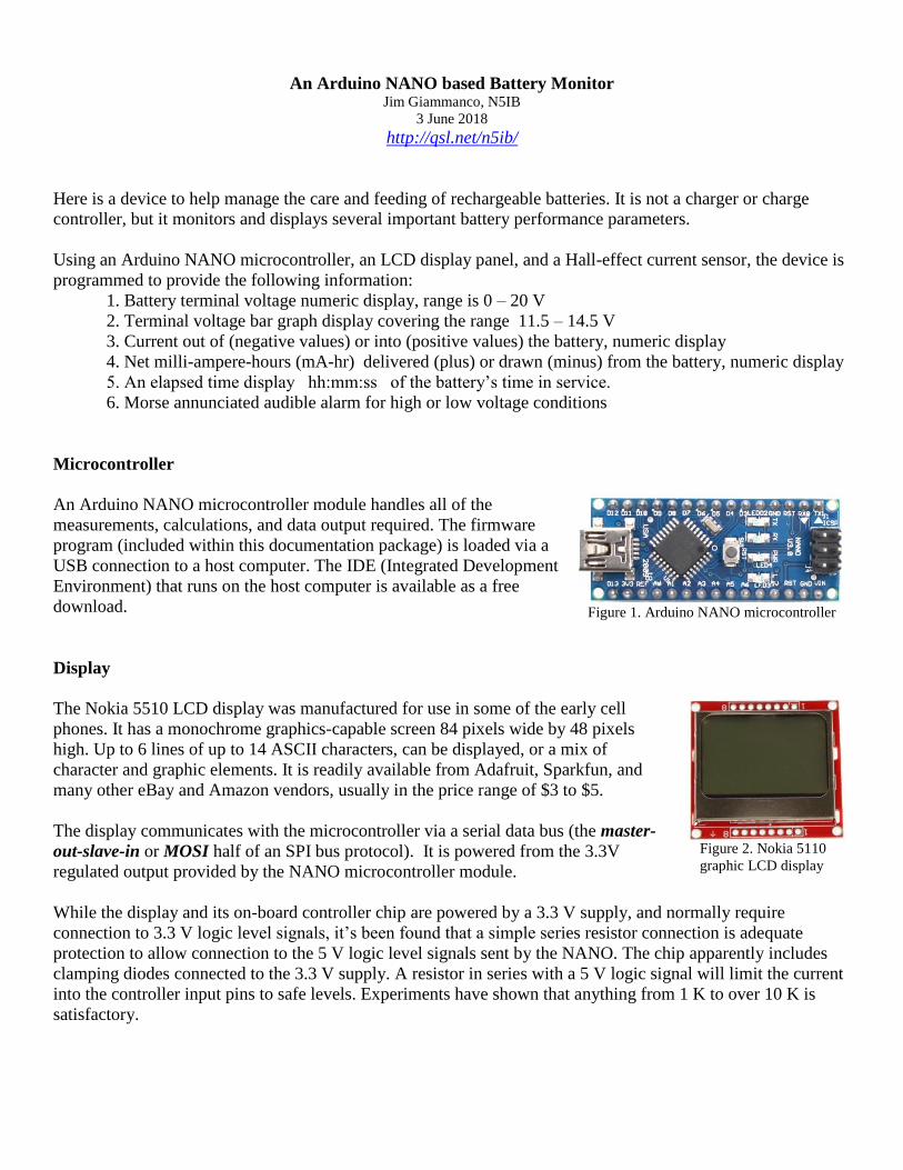
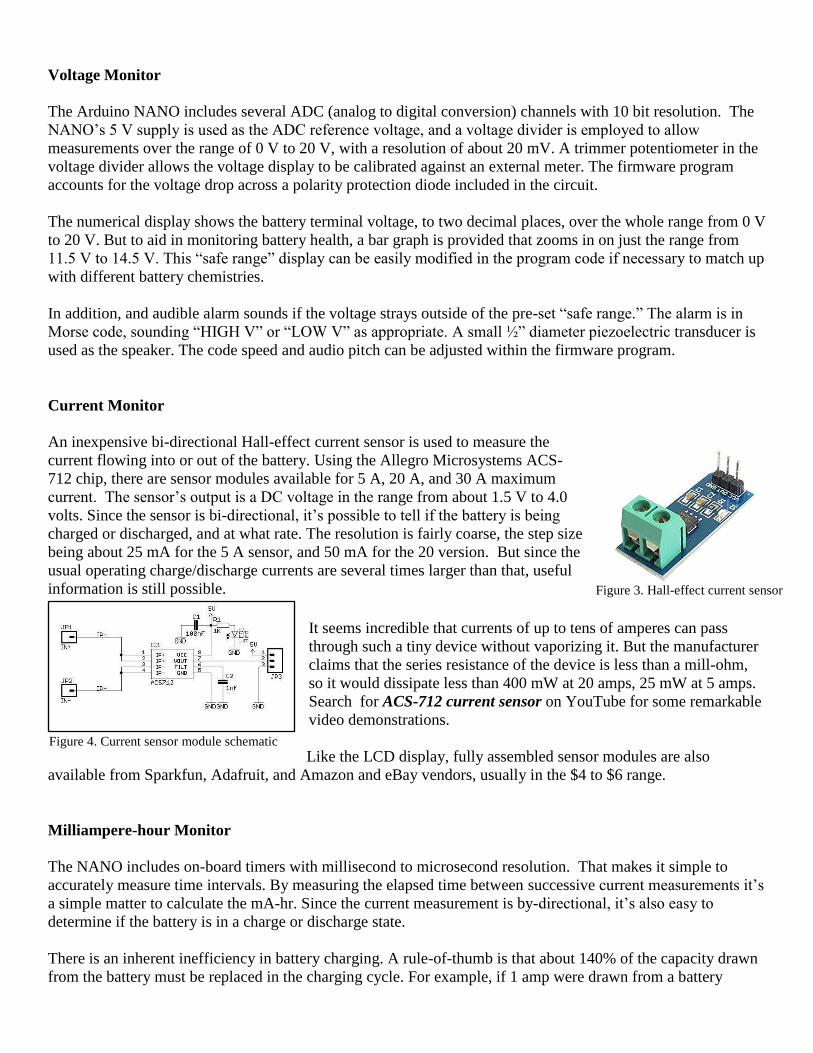
An inexpensive bi-directional Hall-effect current sensor is used to measure the
current flowing into or out of the battery. Using the Allegro Microsystems ACS-
712 chip, there are sensor modules available for 5 A, 20 A, and 30 A maximum
current. The sensor’s output is a DC voltage in the range from about 1.5 V to 4.0
volts. Since the sensor is bi-directional, it’s possible to tell if the battery is being
charged or discharged, and at what rate. The resolution is fairly coarse, the step size
being about 25 mA for the 5 A sensor, and 50 mA for the 20 version. But since the
usual operating charge/discharge currents are several times larger than that, useful
information is still possible.
It seems incredible that currents of up to tens of amperes can pass
through such a tiny device without vaporizing it. But the manufacturer
claims that the series resistance of the device is less than a mill-ohm,
so it would dissipate less than 400 mW at 20 amps, 25 mW at 5 amps.
Search for ACS-712 current sensor on YouTube for some remarkable
video demonstrations.
Like the LCD display, fully assembled sensor modules are also
available from Sparkfun, Adafruit, and Amazon and eBay vendors, usually in the $4 to $6 range.
Milliampere-hour Monitor
The NANO includes on-board timers with millisecond to microsecond resolution. That makes it simple to
accurately measure time intervals. By measuring the elapsed time between successive current measurements it’s
a simple matter to calculate the mA-hr. Since the current measurement is by-directional, it’s also easy to
determine if the battery is in a charge or discharge state.
There is an inherent inefficiency in battery charging. A rule-of-thumb is that about 140% of the capacity drawn
from the battery must be replaced in the charging cycle. For example, if 1 amp were drawn from a battery
Figure 3. Hall-effect current sensor
Figure 4. Current sensor module schematic
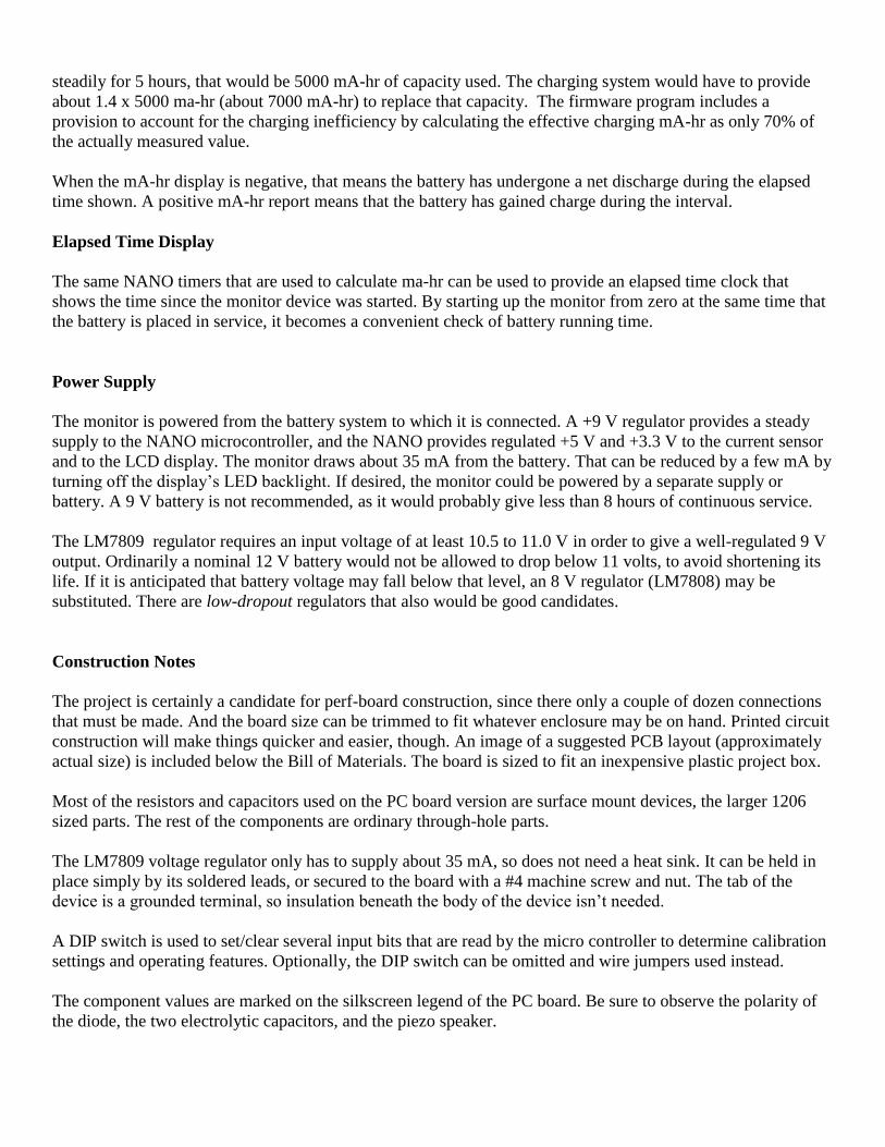
steadily for 5 hours, that would be 5000 mA-hr of capacity used. The charging system would have to provide
about 1.4 x 5000 ma-hr (about 7000 mA-hr) to replace that capacity. The firmware program includes a
provision to account for the charging inefficiency by calculating the effective charging mA-hr as only 70% of
the actually measured value.
When the mA-hr display is negative, that means the battery has undergone a net discharge during the elapsed
time shown. A positive mA-hr report means that the battery has gained charge during the interval.
Elapsed Time Display
The same NANO timers that are used to calculate ma-hr can be used to provide an elapsed time clock that
shows the time since the monitor device was started. By starting up the monitor from zero at the same time that
the battery is placed in service, it becomes a convenient check of battery running time.
Power Supply
The monitor is powered from the battery system to which it is connected. A +9 V regulator provides a steady
supply to the NANO microcontroller, and the NANO provides regulated +5 V and +3.3 V to the current sensor
and to the LCD display. The monitor draws about 35 mA from the battery. That can be reduced by a few mA by
turning off the display’s LED backlight. If desired, the monitor could be powered by a separate supply or
battery. A 9 V battery is not recommended, as it would probably give less than 8 hours of continuous service.
The LM7809 regulator requires an input voltage of at least 10.5 to 11.0 V in order to give a well-regulated 9 V
output. Ordinarily a nominal 12 V battery would not be allowed to drop below 11 volts, to avoid shortening its
life. If it is anticipated that battery voltage may fall below that level, an 8 V regulator (LM7808) may be
substituted. There are low-dropout regulators that also would be good candidates.
Construction Notes
The project is certainly a candidate for perf-board construction, since there only a couple of dozen connections
that must be made. And the board size can be trimmed to fit whatever enclosure may be on hand. Printed circuit
construction will make things quicker and easier, though. An image of a suggested PCB layout (approximately
actual size) is included below the Bill of Materials. The board is sized to fit an inexpensive plastic project box.
Most of the resistors and capacitors used on the PC board version are surface mount devices, the larger 1206
sized parts. The rest of the components are ordinary through-hole parts.
The LM7809 voltage regulator only has to supply about 35 mA, so does not need a heat sink. It can be held in
place simply by its soldered leads, or secured to the board with a #4 machine screw and nut. The tab of the
device is a grounded terminal, so insulation beneath the body of the device isn’t needed.
A DIP switch is used to set/clear several input bits that are read by the micro controller to determine calibration
settings and operating features. Optionally, the DIP switch can be omitted and wire jumpers used instead.
The component values are marked on the silkscreen legend of the PC board. Be sure to observe the polarity of
the diode, the two electrolytic capacitors, and the piezo speaker.
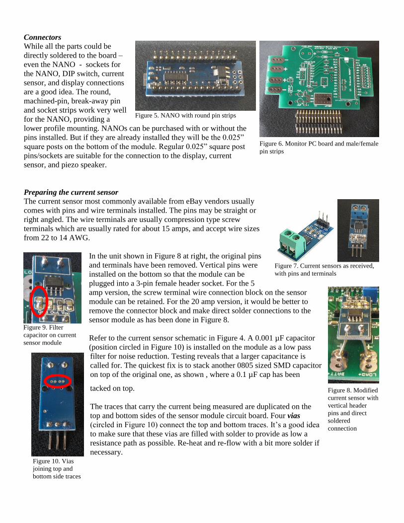
Connectors While all the parts could be
directly soldered to the board –
even the NANO - sockets for
the NANO, DIP switch, current
sensor, and display connections
are a good idea. The round,
machined-pin, break-away pin
and socket strips work very well
for the NANO, providing a
lower profile mounting. NANOs can be purchased with or without the
pins installed. But if they are already installed they will be the 0.025”
square posts on the bottom of the module. Regular 0.025” square post
pins/sockets are suitable for the connection to the display, current
sensor, and piezo speaker.
Preparing the current sensor
The current sensor most commonly available from eBay vendors usually
comes with pins and wire terminals installed. The pins may be straight or
right angled. The wire terminals are usually compression type screw
terminals which are usually rated for about 15 amps, and accept wire sizes
from 22 to 14 AWG.
In the unit shown in Figure 8 at right, the original pins
and terminals have been removed. Vertical pins were
installed on the bottom so that the module can be
plugged into a 3-pin female header socket. For the 5
amp version, the screw terminal wire connection block on the sensor
module can be retained. For the 20 amp version, it would be better to
remove the connector block and make direct solder connections to the
sensor module as has been done in Figure 8.
Refer to the current sensor schematic in Figure 4. A 0.001 µF capacitor
(position circled in Figure 10) is installed on the module as a low pass
filter for noise reduction. Testing reveals that a larger capacitance is
called for. The quickest fix is to stack another 0805 sized SMD capacitor
on top of the original one, as shown , where a 0.1 µF cap has been
tacked on top.
The traces that carry the current being measured are duplicated on the
top and bottom sides of the sensor module circuit board. Four vias
(circled in Figure 10) connect the top and bottom traces. It’s a good idea
to make sure that these vias are filled with solder to provide as low a
resistance path as possible. Re-heat and re-flow with a bit more solder if
necessary.
Figure 5. NANO with round pin strips
installed
Figure 6. Monitor PC board and male/female
pin strips
Figure 7. Current sensors as received,
with pins and terminals
Figure 8. Modified
current sensor with
vertical header
pins and direct
soldered
connection
Figure 9. Filter
capacitor on current
sensor module
Figure 10. Vias
joining top and
bottom side traces
Preparing the LCD display panel
The LCD display panels usually are sold with one set of vertical header pins
already installed. A second set of eight circuit board pads is also provided.
Connection to the display can be made at either pad set, or even a combination
of the two. The pads are wired in parallel.
Depending on how the display will be mounted in an enclosure, it is possible
that the vertical pins may interfere with components below the display. This
was the case in the unit pictured. The vertical header pins were removed and a
right angled female header substituted.
DuPont type wire connectors can be used to connect the display to the header
on the main circuit board.
ON/OFF Switch
If a switch is to be installed, its wire leads can be soldered directly to the pads at the SW1 position. Or a 2-pin
header can be installed at that position to accept a plug-in connection. Note: the SW1 pads are placed a little too close to the position of the current sensor module. If a header/socket arrangement is to be
used, the header pins should be slightly angled out towards the diode so that the plug assembly will clear the edge of the sensor
module.
Piezo speaker
In order to make the Morse annunciation audible, the small piezo speaker should be mounted beneath a small
hole drilled in the enclosure. Glue or double sided tape can be used to fix it in place. The speaker is polarized.
One of its pins is marked “+” so be sure to observe the polarity when connecting it to the PC board.
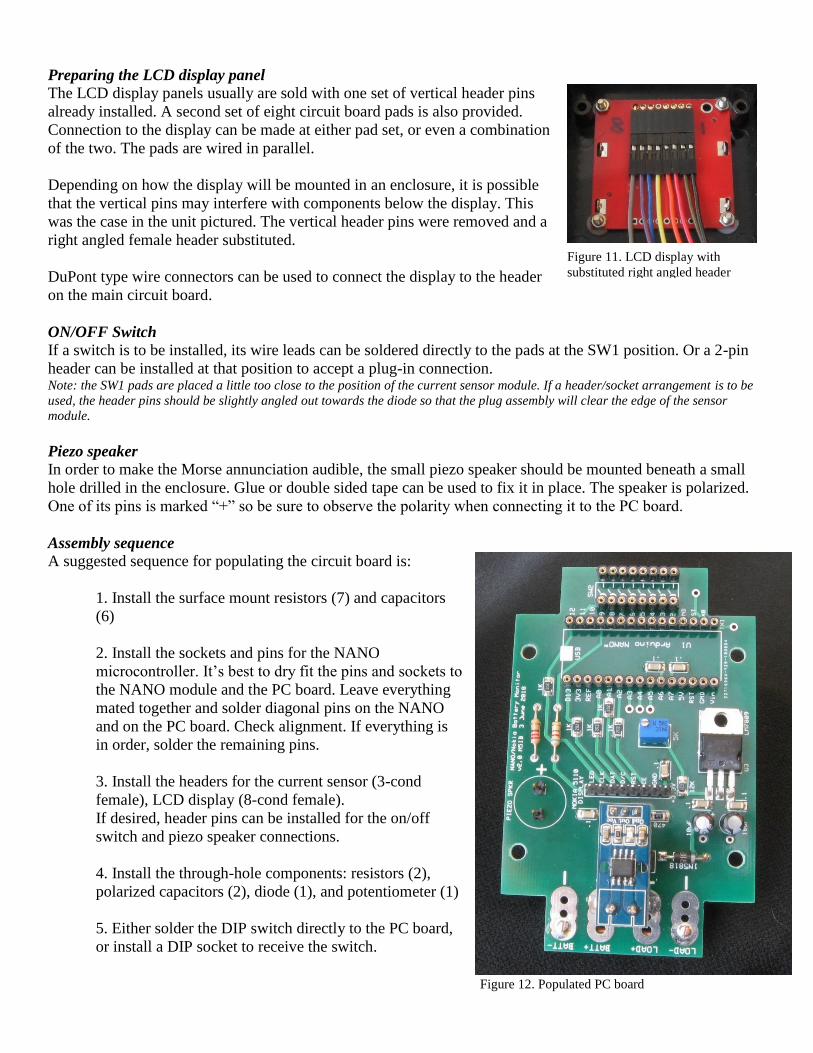
Assembly sequence
A suggested sequence for populating the circuit board is:
1. Install the surface mount resistors (7) and capacitors
(6)
2. Install the sockets and pins for the NANO
microcontroller. It’s best to dry fit the pins and sockets to
the NANO module and the PC board. Leave everything
mated together and solder diagonal pins on the NANO
and on the PC board. Check alignment. If everything is
in order, solder the remaining pins.
3. Install the headers for the current sensor (3-cond
female), LCD display (8-cond female).
If desired, header pins can be installed for the on/off
switch and piezo speaker connections.
4. Install the through-hole components: resistors (2),
polarized capacitors (2), diode (1), and potentiometer (1)
5. Either solder the DIP switch directly to the PC board,
or install a DIP socket to receive the switch.
Figure 11. LCD display with
substituted right angled header
Figure 12. Populated PC board

6. The negative terminals from the battery and load/charging
source are connected together by a heavy copper wire on the
bottom of the PC board. Input and output wire leads are also
soldered to the pads on the underside of the board.
7. Install the LM7809 voltage regulator. It may be secured
to the PC board with a #4 screw and nut, but that is optional.
No heat sink is needed.
Enclosure
The PC board is sized to fit the PB-03 project box sold by
Tayda Electronics. The rubber feet are on the shallow
section of the box, so that becomes the bottom, and the
circuit board is mounted there. One end of the bottom
section is notched to allow the input and output wire leads
to exit the box, as shown in Figure 15.
The LCD display, ON/OFF switch, and piezo speaker are
mounted in the deeper, upper section of the box.
There are solder fillets along the header pads on the top
side of the LCD board. These would prevent the board
from lying flat when mounted, so washers are used at the
four corners to space the board slightly.
Figure 13. Negative battery and load leads
jumpered
Figure 14. Side views of populated PC board, mounted into the bottom section of the plastic enclosure
Figure 15. Additional views of populated PC board, including piezo speaker connected
connection (right)
Figure 16. LCD display and ON/OFF switch mounted into
the top section of the enclosure. Note the use of washers at
the four corners of the display. Also note the double sided
tape in place to secure the piezo speaker

Program Loading
There are two ways to load the firmware program into the Arduino NANO. One is to use the Arduino
Integrated Development Environment (IDE) to compile the source code and then upload it via a USB
connection from a host computer. The other is to use the USB connection to upload the already compiled
program from a .HEX file.
The program is saved as a compressed (zip) folder at: http://qsl.net/n5ib/BatMon_Morse.zip
that contains several files: BatMon_Morse.ino the main source code file
BatMon_Morse_Defs.h variable declarations, definitions, and initial settings
BatMon_Morse.hex the compiled code ready for direct upload
BatMon_Morse.pdf this document
Nokia 5110 Datasheet.pdf Nokia 5110 LCD display controller datasheet
ACS712-Datasheet.pdf ACS-712 Hall-effect current sensor data sheet
Tayda PB-03 Plastic Project box A-2383.pdf dimensioned drawing of PB-03 enclosure
All of these files should be extracted from the compressed folder into a folder named “BatMon_Morse”
Only the first two are needed if the builder wishes to compile the code and then upload.
Only the third file is needed for direct upload. The rest are reference documents.
The source code is fairly well commented to assist the builder in customizing the operation of the monitor or for
adding new features.
Operation of the Arduino IDE and/or the hex loader is beyond the scope of this document. But there are lots of
tutorials and guidance available in the on-line Arduino community.
Initial Checkout
Refer to the table below and initially set the DIP switches to: Enable CW annunciation
Enable backlight
Offset bits 000
Offset sign positive
Current sensor max set for the sensor that is installed
The DIP switches are connected between the NANO’s digital input pins and ground. The
inputs are pulled up to +5V by internal resistors. So a switch in the “OFF” or “OPEN”
position will be read as a logic “1” while a switch in the “ON” or “CLOSED” position will be
read as a logic “0.” Position OFF - OPEN circuit – Logic Level “1” ON - CLOSED Circuit – Logic Level “0”
1 Enable CW annunciation Disable CW annunciation
2 Enable LED backlight Disable LED backlight
3 Bit 0 (LSB) of offset = 1 Bit 0 of offset = 0
4 Bit 1 of offset = 1 Bit 1 of offset = 0
5 Bit 2 (MSB) of offset = 1 Bit 2 of offset = 0
6 Sign of current sensor offset = NEGATIVE Sign of current sensor offset = positive
7 Current sensor maximum = 20 A Current sensor maximum = 5 A
8 (spare)
If the optional power ON/OFF switch is used, set it to OFF.
Connect the BATT+ and BATT- leads to a 12 volt battery
The LOAD+ and LOAD- leads may be left unconnected at this time
Turn the power switch ON
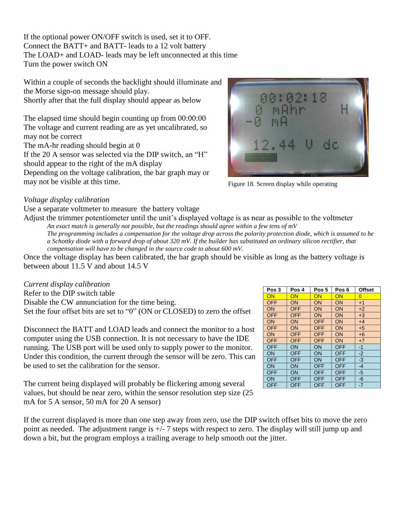
Within a couple of seconds the backlight should illuminate and
the Morse sign-on message should play.
Shortly after that the full display should appear as below
The elapsed time should begin counting up from 00:00:00
The voltage and current reading are as yet uncalibrated, so
may not be correct
The mA-hr reading should begin at 0
If the 20 A sensor was selected via the DIP switch, an “H”
should appear to the right of the mA display
Depending on the voltage calibration, the bar graph may or
may not be visible at this time.
Voltage display calibration
Use a separate voltmeter to measure the battery voltage
Adjust the trimmer potentiometer until the unit’s displayed voltage is as near as possible to the voltmeter An exact match is generally not possible, but the readings should agree within a few tens of mV
The programming includes a compensation for the voltage drop across the polarity protection diode, which is assumed to be
a Schottky diode with a forward drop of about 320 mV. If the builder has substituted an ordinary silicon rectifier, that
compensation will have to be changed in the source code to about 600 mV.
Once the voltage display has been calibrated, the bar graph should be visible as long as the battery voltage is
between about 11.5 V and about 14.5 V
Current display calibration
Refer to the DIP switch table
Disable the CW annunciation for the time being.
Set the four offset bits are set to “0” (ON or CLOSED) to zero the offset
Disconnect the BATT and LOAD leads and connect the monitor to a host
computer using the USB connection. It is not necessary to have the IDE
running. The USB port will be used only to supply power to the monitor.
Under this condition, the current through the sensor will be zero. This can
be used to set the calibration for the sensor.
The current being displayed will probably be flickering among several
values, but should be near zero, within the sensor resolution step size (25
mA for 5 A sensor, 50 mA for 20 A sensor)
If the current displayed is more than one step away from zero, use the DIP switch offset bits to move the zero
point as needed. The adjustment range is +/- 7 steps with respect to zero. The display will still jump up and
down a bit, but the program employs a trailing average to help smooth out the jitter.
Pos 3 Pos 4 Pos 5 Pos 6 Offset
ON ON ON ON 0
OFF ON ON ON +1
ON OFF ON ON +2
OFF OFF ON ON +3
ON ON OFF ON +4
OFF ON OFF ON +5
ON OFF OFF ON +6
OFF OFF OFF ON +7
OFF ON ON OFF -1
ON OFF ON OFF -2
OFF OFF ON OFF -3
ON ON OFF OFF -4
OFF ON OFF OFF -5
ON OFF OFF OFF -6
OFF OFF OFF OFF -7
Figure 18. Screen display while operating

Normal operation
Enable the CW annunciation if audible alarms are desired
Connect a 12 V battery to the BATT+ and BATT- leads
The monitor should start up with the time and mA-hrs zeroed Be sure to always connect the battery first. The battery serves as a voltage stabilizer in case a charging source can supply an
excessively high voltage while under very light load.
For example, a solar panel that might only be able to supply a few hundred mA might still have a voltage above 20 V under
open circuit or light load conditions. If the battery is already connected it will supply a load and pull the voltage down.
Connect the load and/or charging source to the LOAD+ and LOAD- leads
The display should begin to show the net current into (+) or out of (-) the battery, and the mA-hr display will
begin to accumulate. Time and mA-hr will reset to zero each time power is cycled.
Ideas for modifications and enhancements
It’s easy to change the source code to do things such as
Change the high and low voltage alarm points
Change the CW sign-on, and alarm messages
Change the backlight brightness
Change the forward diode voltage drop compensation
Change the number of samples in the trailing average for current
Since this is a programmable platform there is a nearly endless variety of things that can be done. There are
three multipurpose I/O pins, presently unused (A3, A4, A5), which can function as analog inputs, or digital
inputs/outputs. Here are just a few thoughts…
Instead of the DIP switches, use momentary contact pushbuttons and program a menu to select operating modes
and features. This will also free up more I/O pins for other features
Use a power MOSFET as a switch to control the charging of the battery
Connect a BlueTooth serial module so that the monitor data can be read remotely (iOS or Android devices?)
Utilize the NANO’s EEPROM non-volatile storage to save/restore the state of the battery instead of resetting to
zero at each power up.
Change the current sensor to one that gives greater precision at low current
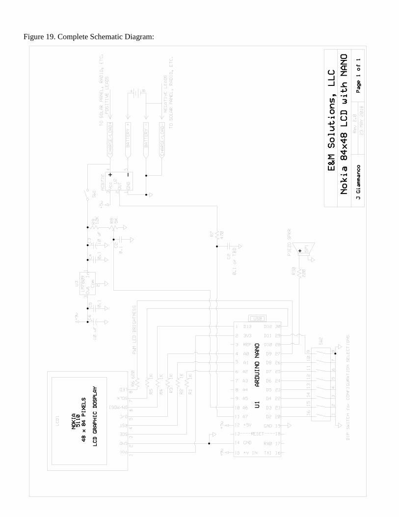
Figure 19. Complete Schematic Diagram:
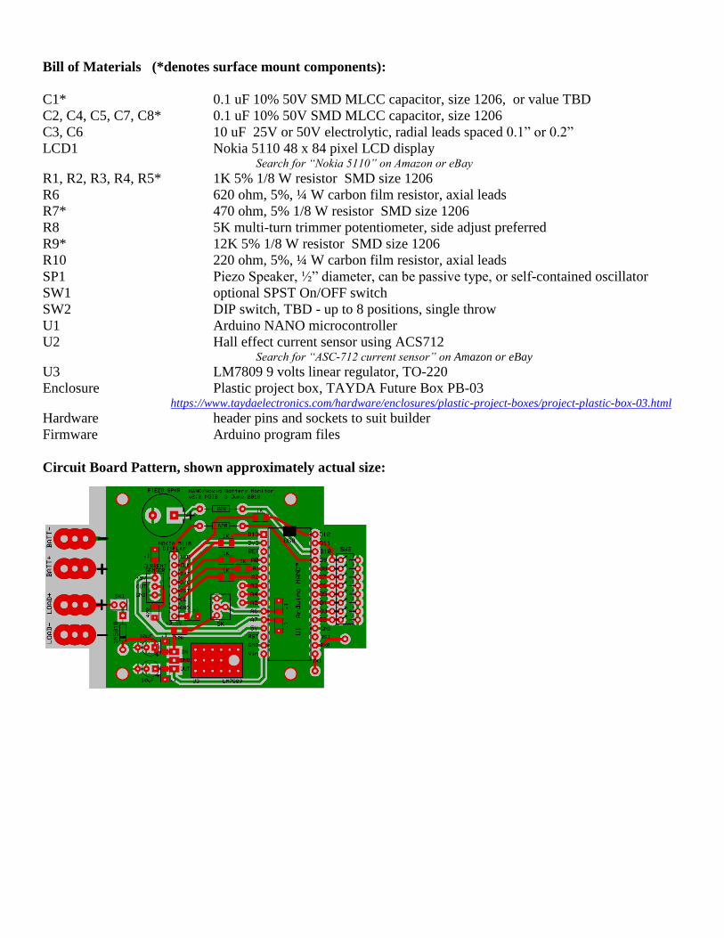
Bill of Materials (*denotes surface mount components):
C1* 0.1 uF 10% 50V SMD MLCC capacitor, size 1206, or value TBD
C2, C4, C5, C7, C8* 0.1 uF 10% 50V SMD MLCC capacitor, size 1206
C3, C6 10 uF 25V or 50V electrolytic, radial leads spaced 0.1” or 0.2”
LCD1 Nokia 5110 48 x 84 pixel LCD display Search for “Nokia 5110” on Amazon or eBay
R1, R2, R3, R4, R5* 1K 5% 1/8 W resistor SMD size 1206
R6 620 ohm, 5%, ¼ W carbon film resistor, axial leads
R7* 470 ohm, 5% 1/8 W resistor SMD size 1206
R8 5K multi-turn trimmer potentiometer, side adjust preferred
R9* 12K 5% 1/8 W resistor SMD size 1206
R10 220 ohm, 5%, ¼ W carbon film resistor, axial leads
SP1 Piezo Speaker, ½” diameter, can be passive type, or self-contained oscillator
SW1 optional SPST On/OFF switch
SW2 DIP switch, TBD - up to 8 positions, single throw
U1 Arduino NANO microcontroller
U2 Hall effect current sensor using ACS712 Search for “ASC-712 current sensor” on Amazon or eBay
U3 LM7809 9 volts linear regulator, TO-220
Enclosure Plastic project box, TAYDA Future Box PB-03 https://www.taydaelectronics.com/hardware/enclosures/plastic-project-boxes/project-plastic-box-03.html
Hardware header pins and sockets to suit builder
Firmware Arduino program files
Circuit Board Pattern, shown approximately actual size:
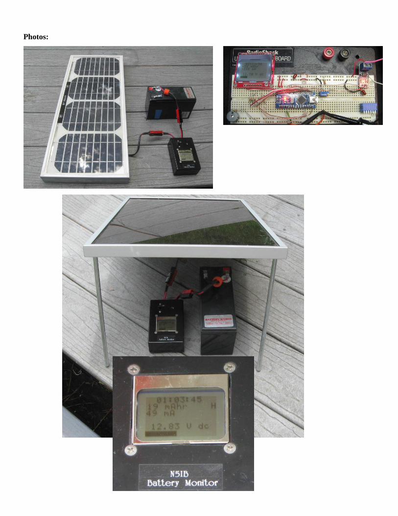
Photos: