Embed Size (px)
Citation preview

International Research Journal of Engineering and Technology (IRJET) e-ISSN: 2395 -0056
Volume: 03 Issue: 07 | July-2016 www.irjet.net p-ISSN: 2395-0072
© 2016, IRJET ISO 9001:2008 Certified Journal Page 353
AN AREA EFFICIENT LTE TURBO DECODER ARCHITECTURE
Farah banu1, Lokeshwari H S2
1 PG Student, Dept. of Electronics and Communication Engineering, Rajeev Institute of Technology Hassan, Karnataka
Email: [email protected] 2 Asst. Professor, Dept. of Electronics and Communication Engineering, Rajeev Institute of Technology
Hassan, Karnataka Email: [email protected]
---------------------------------------------------------------------***---------------------------------------------------------------------
Abstract - In wireless communications, most of the fourth generation mobile systems with LTE (Long Term Evolution) standards are supporting data rates of 300Mbps but now-a-days as the demand for high peak data rates has increased, LTE standards are emerging towards achieving data rates in terms of Gbps. This is accomplished by adopting efficient channel coding schemes. Turbo codes are the best suited for FEC (Forward Error Correction) in channel coding which also has near Shannon error-correcting performance. But at the same time it is also necessary to have compactness in area, so a novel ACS (Add-Compare-Select) unit is proposed which reduces the computational area occupied in the decoder unit.
Key Words: LTE, Turbo decoder block, ACS unit, MSR architecture.
1. INTRODUCTION The wireless communication technology which has connected the people all over the World from anywhere anytime is now rapidly growing on demand to achieve high data rate transmissions. To accomplish this, a reliable channel coding scheme has to be adopted. Turbo codes are one of the high performance channel codes with forward error correction (FEC) which provides optimal performance approaching the Shannon limit. This scheme is mainly used in the digital communication systems where the transmitted signals often get corrupted by noise due to their non-ideal behavior in realistic communication channels. So, turbo codes are used at the most in long term evolution (LTE) systems. In this paper, the architecture of turbo encoder and turbo decoder are proposed. The main aim is to reduce the area occupied by computational units in decoder block by employing the ACS 4 unit along with MSR (Maximum Shared Resource) architecture by simplifying the computations.
2. TURBO ENCODING ARCHITECTURE Turbo encoders are mainly designed by combining 2 recursive systematic convolutional (RSC) encoders by parallel concatenation method which is separated by a single interleaver. Fig-1 shows the block diagram of turbo encoder where the RSC encoder is selected as rate 1/3 encoder.
Fig-1: Turbo encoder.
The input sequence Ek is represented by the binary input values Ek = [E1, E2, E3,........En]. These input sequences are passed into the encoder path1 producing the output of systematic sequence Ok
s and recursive redundant output sequence Ok
p1 called the parity1 encoded bits. The input Ek is then interleaved using a QPP (Quadratic permutation polynomial) or random interleaver. Interleaver is used in-between to enhance the performance of turbo codes. The pseudo random interleaver is usually used, where the data bits are read-out in user designed fashion. These interleaved data sequences are passed through encoder path2 producing the other set of recursive redundant output sequence Ok
p2 called parity2 encoded sequence. Thus the encoder produces three outputs from a single input, hence called the rate 1/3 encoder unit.
3. TURBO DECODING ARCHITECTURE The turbo decoder mainly consists of serially connected soft-input soft-output (SISO) decoders with interleaver in between and the corresponding deinterleaver (it performs reverse operation of interleaver). The outputs of encoded unit serve as input to the decoder unit. Thus the decoder has three inputs Ok
s, Okp1 and Ok
p2which on iterative decoding produces the output Dk. The decoders considered here are

International Research Journal of Engineering and Technology (IRJET) e-ISSN: 2395 -0056
Volume: 03 Issue: 07 | July-2016 www.irjet.net p-ISSN: 2395-0072
© 2016, IRJET ISO 9001:2008 Certified Journal Page 354
MAP (Maximum A Posteriori) decoders. The block representation is shown in fig-2.
Fig-2: Turbo decoder.
The MAP decoder1 recieves the systematic and parity1 data bits, which on decoding produces a soft value which is an extrinsic estimate,these values are interleaved and again layed as input to MAP decoder 2 .after decoding, again the output is sent into the deinterleaver, thus it now consists of second estimated extrinsic valueswhich intern is again fedback into the MAP decoder1. There is continuous iterations taking place between MAP decoder1 and 2 units until the error rate is found to be null.in the last stage simple approximations are performed to obtain the hard decision values at the MAP decoder2 stage.
3.1 Turbo decoder algorithms In 1974, Bahl, Cocke, Jelinek and Raviv proposed the posteriori probabilities based decoding algorithm which later came to be known as MAP algorithm. There are2 other schemes of MAP algorithm which makes the computations easier and faster, they are; log-MAP and Max-log-MAP algorithm. The MAP decoders receive the input binary sequence and estimate the most likely input value. These values are referred to as the log-likelihood ratios also called the soft decisions-having polarity and amplitude. The polarity of log likelihood ratios (LLR) value will provide the sign of the bit and amplitude will give the probability. The LLR value is calculated using;
Where the numerator indicates the APP (A Posteriori
Probability) of input sequence Ek. The turbo decoder
performs the decoding action iteratively i.e., the MAP
decoder1 performs decoding and then its values are passed
to MAP decoder2 via interleaver, then the MAP decoder2
performs estimations after decoding and sends the same to
MAP decoder1, thus first iteration is completed. These values
obtained from serves as priori values for second iteration.
Until the bit error rate is reduced to null or approximately
null, the iterations are performed. The LLR values for
forward, backward and branch metrics are calculated using
the formula,
Where, and are forward and backward traced
directions respectively. Lc and Le are channel reliability and
extrinsic information bits. Max-log-MAP algorithm is a
method where calculated values are rewritten in logarithmic
domain to simplify calculations.
For forward metrics (α) with length h=0,1,…k-1 and states
‘t’i.e., h+1(t) is given by,
h+1(t)=max*[ h(ti’,t)+ i(ti)’,( i (t’j,t)+ h(tj’)] (7)
Similarly for β,
h(j’)=max*[ h(t’,ti)+ h+1( ti),( h(t’,tj)+ h+1( tj)] (8)
3.2 ACS units The forward and backward recursion computation is calculated using ACS architecture. The radix2 ACS architecture is shown in fig-3.
Fig-3: Radix2 ACS unit.
International Research Journal of Engineering and Technology (IRJET) e-ISSN: 2395 -0056
Volume: 03 Issue: 07 | July-2016 www.irjet.net p-ISSN: 2395-0072
© 2016, IRJET ISO 9001:2008 Certified Journal Page 355
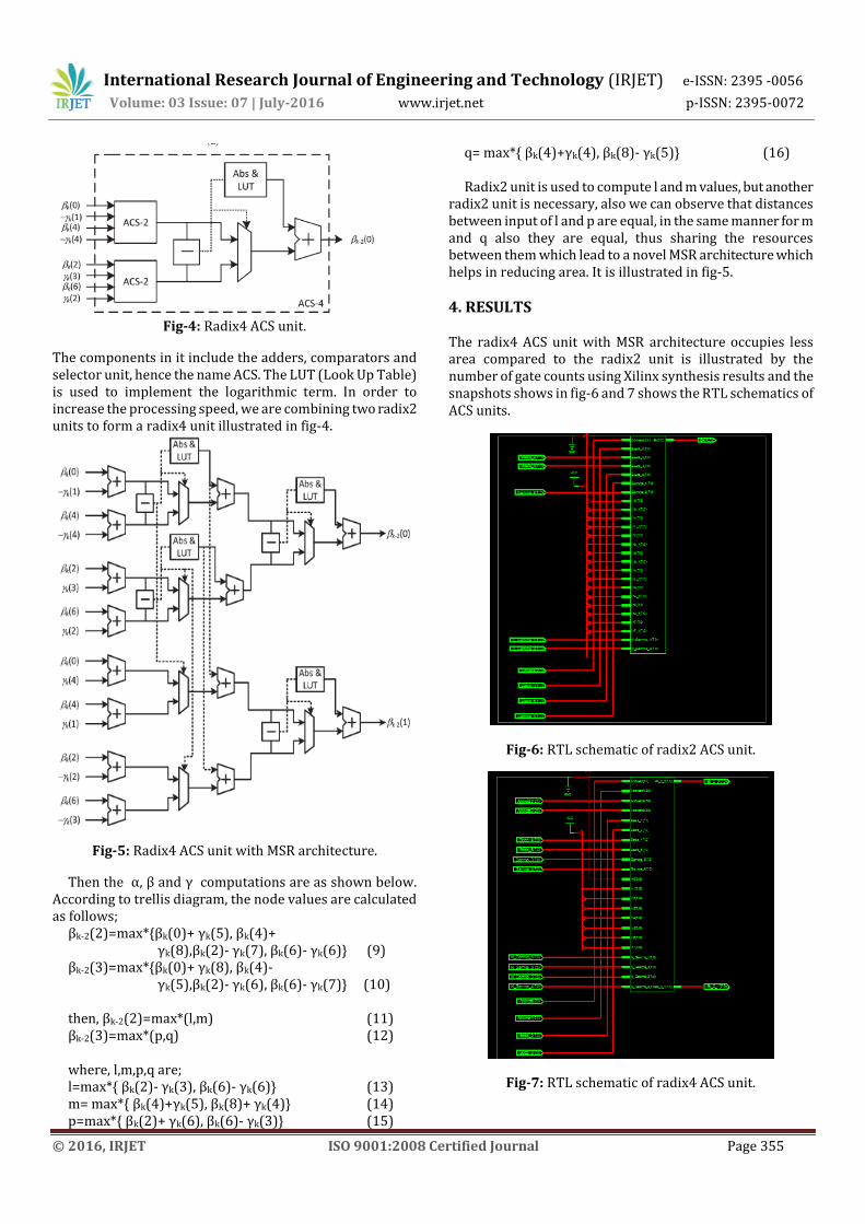
Fig-4: Radix4 ACS unit.
The components in it include the adders, comparators and selector unit, hence the name ACS. The LUT (Look Up Table) is used to implement the logarithmic term. In order to increase the processing speed, we are combining two radix2 units to form a radix4 unit illustrated in fig-4.
Fig-5: Radix4 ACS unit with MSR architecture.
Then the α, β and γ computations are as shown below. According to trellis diagram, the node values are calculated as follows;
βk-2(2)=max*{βk(0)+ γk(5), βk(4)+ γk(8),βk(2)- γk(7), βk(6)- γk(6)} (9) βk-2(3)=max*{βk(0)+ γk(8), βk(4)- γk(5),βk(2)- γk(6), βk(6)- γk(7)} (10) then, βk-2(2)=max*(l,m) (11) βk-2(3)=max*(p,q) (12) where, l,m,p,q are; l=max*{ βk(2)- γk(3), βk(6)- γk(6)} (13) m= max*{ βk(4)+γk(5), βk(8)+ γk(4)} (14) p=max*{ βk(2)+ γk(6), βk(6)- γk(3)} (15)
q= max*{ βk(4)+γk(4), βk(8)- γk(5)} (16)
Radix2 unit is used to compute l and m values, but another radix2 unit is necessary, also we can observe that distances between input of l and p are equal, in the same manner for m and q also they are equal, thus sharing the resources between them which lead to a novel MSR architecture which helps in reducing area. It is illustrated in fig-5.
4. RESULTS The radix4 ACS unit with MSR architecture occupies less area compared to the radix2 unit is illustrated by the number of gate counts using Xilinx synthesis results and the snapshots shows in fig-6 and 7 shows the RTL schematics of ACS units.
Fig-6: RTL schematic of radix2 ACS unit.
Fig-7: RTL schematic of radix4 ACS unit.
International Research Journal of Engineering and Technology (IRJET) e-ISSN: 2395 -0056
Volume: 03 Issue: 07 | July-2016 www.irjet.net p-ISSN: 2395-0072
© 2016, IRJET ISO 9001:2008 Certified Journal Page 356
5. CONCLUSION
An area efficient MSR architecture has been proposed which achieves maximum reduction in area which reduces the MAP decoding computational complexity in the turbo decoder. In future the higher order radix can be used to increase the speed and to reduce the circuit complexity.
REFERENCES [1] Arash Ardakani and Mahdi Shabany, “A Novel Area-
Efficient VLSI Architecture for Recursion Computation in LTE Turbo Decoders”, IEEE Transactions on Circuits and Systems—Ii: Express Briefs, Vol. 62, No. 6, June 2015.
[2] C. Berrou and A. Glavieux, “Near optimum error correcting coding and decoding: Turbo-codes,” IEEE Trans. Commun., vol. 44, no. 10, pp. 1261–1271, Oct. 1996.
[3] V. Franz and J. Anderson, “Concatenated decoding with a reducedsearch BCJR algorithm,” IEEE J. Sel. Areas Commun., vol. 16, no. 2, pp. 186–195, Feb. 1998.
[4] J. Woodard and L. Hanzo, “Comparative study of turbo decoding techniques: An overview,” IEEE Trans. Veh. Technol., vol. 49, no. 6, pp. 2208–2233, Nov. 2000.
[5] C. Studer, C. Benkeser, S. Belfanti, and Q. Huang, “Design and implementation of a parallel turbo-decoder ASIC for 3GPP-LTE,” IEEE J. Solid-State Circuits, vol. 46, no. 1, pp. 8–17, Jan. 2011.
BIOGRAPHIES Farah Banu received the B.E.
degree in Electronics and communication Engineering,RIT, Hassan, Karnataka, in 2014 and pursuing M.Tech(VLSI design & embedded systems)in RIT, Hassan. Her research interest includes Error correction codes used in wireless communication.
Lokeshwari H S, graduated from Yelamma Dasappa Institute of Technology, Bangalore in 2010 and pursued post graduation with the specialization of Digital Electronics and Communication System at Adichunchanagiri Institute of Technology, Chikmaglur in 2012. Her interested subjects are embedded systems and wireless communication.
1’st Author Photo
2nd Author Photo