Embed Size (px)
Citation preview
BMI-X-660
AN ASSESSMENT OF THE POTENTIALLY BENEFICIAL USES OF KRYPTON-85
Final Report, Task 64
BATTELLE Columbus Laboratories
505 King Avenue Columbus, Ohio 43201
DISCLAIMER
This report was prepared as an account of work sponsored by an agency of the United States Government. Neither the United States Government nor any agency Thereof, nor any of their employees, makes any warranty, express or implied, or assumes any legal liability or responsibility for the accuracy, completeness, or usefulness of any information, apparatus, product, or process disclosed, or represents that its use would not infringe privately owned rights. Reference herein to any specific commercial product, process, or service by trade name, trademark, manufacturer, or otherwise does not necessarily constitute or imply its endorsement, recommendation, or favoring by the United States Government or any agency thereof. The views and opinions of authors expressed herein do not necessarily state or reflect those of the United States Government or any agency thereof.

DISCLAIMER Portions of this document may be illegible in electronic image products. Images are produced from the best available original document.
This report was prepared as an account of work sponsored by the United States Government. Neither the United States nor the United States Energy Research and Development Administration, nor any of their employees, nor any of their contractors, subcontractors, or their employees, makes any warranty, express or implied, or assunnes any legal liability or responsibility for the accuracy, completeness or usefulness of any information, apparatus, product or process disclosed, or represents that its use would not infringe privately owned rights.
BMI-X-660
AN ASSESSMENT OF THE POTENTIALLY BENEFICIAL USES OF KRYPTON-85
Final Report, Task 64
Philip E. Eggers William E. Gawthrop
BATTELLE Columbus Laboratories
505 King Avenue Columbus, Ohio 43201
NOTICE This report was prepared as an account of work sponsored by the United States Government Neither the United States nor the United States Energy Research and Development Administration, nor any of their employees, nor any of their contractors, subcontractors, or their employees, makes any warranty, express or impbed, or assumes any legaJ liabibty or responsibibty for the accuracy, completeness or usefulness of any information, apparatus, product or process disUosed, or represents that its use would not mfnnge pnvalely owned rights
Prepared for United States Energy Research and Development Administration Under Contract W-7405-eng-92
Report Date: June, 1975
>
DrSTRlBUTiCN OF THIS DOCdulENT fS UNLir /slTED
TABLE OF CONTENTS
INTRODUCTION 1
SUMMARY 2
RECOMMENDATIONS 5
BACKGROUND AND CHARACTERISTICS OF KRYPTON-85 5
Properties, Collection, and Enrichment 5
Output by the Nuclear Power Industry 8
TECHNICAL ASSESSMENTS 8
Self-Lumlnous Light Sources 8
Lights for Underground Mines 18
Lights for Inland Waterways 24
Lights for Airport Visual Aids 24
Other Lighting Concepts 30
Military Applications 31
Conclusions 34
Technical Assessment of Radioisotope Thermoelectric
Generators Involving Krypton-85 Heat Sources 34
Introduction 34
Description of Selected RTG Concepts 36
One Watt(e) RTG 37
Forty-^llllwatt(e) RTG 39
Potential Benefits of Kr3T)ton-85 RTG's 42
Potential Limitations of Krypton-85 RTG's 42
Conclusions 43
Dynamic Energy Conversion Systems 44
Brayton-Cycle Systems 46
Stirling-Cycle Engines 47
Ranklne-Cycle Engines 48
Conclusions 49
Polymerization 49
Conclusions 51
Concepts Based on Property 1 51
Concepts Based on Property 2 51
Concepts Based on Properties 5 and 6 53
TABLE OF CONTENTS (Continued)
Page
Nondestructive Testing 54
Gauging 54
Leak Detection and Fluid Flow Tracing 55
Flaw Detection and Thermal Mapping 56
Miscellaneous Applications 57
Conclusions 58
Biomedical Applications 59
Conclusions 60
Waste Treatment 61
Specific Applications 64
Military Unique Waste Disposal or
Waste Treatments 64
Germ-Warfare Agents 65
Chemical-Warfare Agents 65
GB and VX 66
Persistent Organics in Wastewater 66
Conclusions 67
Environmental Control of Submerslbles 69
Submersible Environmental Control System 69
Personnel Transfer Capsule Environmental
Control Gas Heater 70
Wet Suit or Dry Suit Diver Heating System 70
Submersible Battery Heaters 70
Conclusions 71
REFERENCES 72
APPENDIX A
SELECTED PHYSICAL PROPERTIES OF KRYPTON-85
APPENDIX B
THE NUCLEAR POWER INDUSTRY
APPENDIX C
QUANTITATIVE ESTIMATION OF KRYPTON-85 QUANTITIES REQUIRED TO DESTROY
REFRACTORY MOLECULES
LIST OF TABLES
Page
Table 1. Comparative Properties of Three Radioisotopes Used for Self-Lumlnous Lighting Applications ^^
Table 2. Comparisons of Some Common Levels of Brightness . . . . i^
Table 3. Candidate Applications for Krypton-85 Self-Lumlnous Lights 17
Table 4. Dynamic Energy Conversion System Applications 45
LIST OF FIGURES
Figure 1. Projected Cimiulative Availability of Krypton From Light Water Reactors(21) 10
Figure 2. Maximum Visible Distance as a Function of Activity of Krypton-85 14
Figure 3. Increase in Maximum Visible Distance by Optically Increasing the Diameter of Source 15
Figure 4. Bare Source Radiation Profiles as a Function of
Brightness 16
Figure 5. Flat Pan Krypton-85 Self-Lumlnous Light Source . . . . 19
Figure 6. Reflector - Type Krypton-85 Self-Lumlnous Light Source 20
Figure 7. Concept for Krypton-85 Self-Ltraiinous Light Source Used as a Delineation Device in Underground Mines (Passageway Cross-Sectional View Shown Above) 22
Figure 8. Concept for Krypton-85 Self-Lumlnous Light Source Used as a Form of Low-Level Area Illumination 23
Figure 9. Concept for High-Intensity Krypton-85 Self-Lumlnous Light Used in a Buoy 25
Figure 10. Concept for a Krypton-85 Self-Lvimlnous Light Source Used as a Barge Marker 26
Figure 11. Concept for a Krypton-85 Self-Lumlnous Light Source Used as a Pier Marker 27
Figure 12. Sketch of a Krypton-85 Runway Marker From a Photograph Supplied by Permission of American Atomics Corporation, Tucson, Arizona 28
Figure 13. Concept for Krypton-85 Self-Lumlnous Light Source Used for Runway Delineation 29
Figure 14. Concept for a Fixed Installation Physical Perimeter Security System Using a Krypton-85 Self-Luminous Light Source 32
Figure 15. Concept for a Field Installation Physical Perimeter Security System Using Krypton-85 Self-Lumlnous Light Sources 33
Figure 16. Schematic View of l-Watt(e) RTG Featuring Krypton-85 Heat Source 38
Figure 17. Schematic View of 40-Milllwatt(e) RTG Featuring Kr3T)ton-85 Heat Source 40
Figure 18. Disc-Shaped Thermoelectric Module Concept Featuring Thin-Film Thermoelements 41
Figure 19. Quantity of Cobalt-60 That can be Afforded for Different Treatment Costs for a 1-MGD Treatment Plant 63
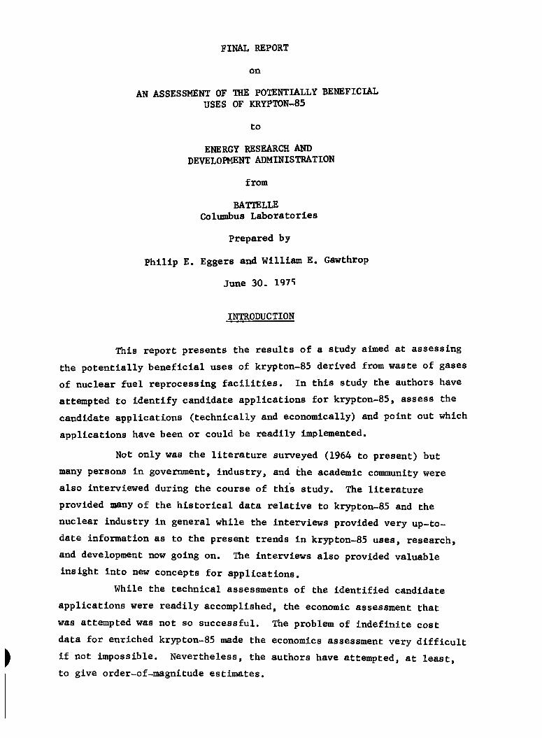
FINAL REPORT
on
AN ASSESSMENT OF THE POTENTIALLY BENEFICUL USES OF KRYPTON-85
to
ENERGY RESEARCH AND DEVELOPMENT ADMINISTRATION
from
BATTELLE Columbus Laboratories
Prepared by
Philip E. Eggers and William E. Gawthrop
June 30. 197S
INTRODUCTION
This report presents the results of a study aimed at assessing
the potentially beneficial uses of krjT)ton-85 derived from waste of gases
of nuclear fuel reprocessing facilities. In this study the authors have
attempted to identify candidate applications for krypton-85, assess the
candidate applications (technically and economically) and point out which
applications have been or could be readily implemented.
Not only was the literature surveyed (1964 to present) but
many persons in government, industry, and the academic community were
also interviewed during the course of this study. The literature
provided many of the historical data relative to krypton-85 and the
nuclear Industry in general while the interviews provided very up-to-
date information as to the present trends in krypton-85 uses, research,
and development now going on. The interviews also provided valuable
insight into new concepts for applications.
While the technical assessments of the identified candidate
applications were readily accomplished, the economic assessment that
was attempted was not so successful. The problem of indefinite cost
data for enriched krypton-85 made the economics assessment very difficult
if not Impossible. Nevertheless, the authors have attempted, at least,
to give order-of-magnltude estimates.
2
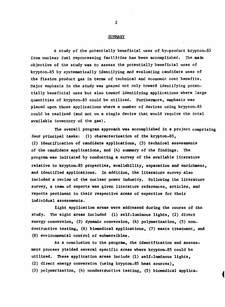
Sm^lARY
A study of the potentially beneficial uses of by-product krypton-85
from nuclear fuel reprocessing facilities has been accomplished. The main
objective of the study was to assess the potentially beneficial uses of
kr3T)ton-85 by systematically identifying and evaluating candidate uses of
the fission product gas in terms of technical and economic cost benefits.
Major emphasis in the study was geared not only toward identifying poten
tially beneficial uses but also toward identifying applications where large
quantities of krypton-85 could be utilized. Furthermore, emphasis was
placed upon those applications where a number of devices using krypton-85
could be realized (and not on a single device that would require the total
available inventory of the gas).
The overall program approach was accomplished In a project comprising
four principal tasks: (1) characterization of the krypton-85,
(2) identification of candidate applications, (3) technical assessments
of the candidate applications, and (4) summary of the findings. The
program was initiated by conducting a survey of the available literature
relative to krypton-85 properties, availability, separation and enrichment,
and identified applications. In addition, the literature survey also
Included a review of the nuclear power Industry. Following the literature
survey, a team of experts was given literature references, articles, and
reports pertinent to their respective areas of expertise for their
individual assessments.
Eight application areas were addressed during the course of the
study. The eight areas Included (1) self-luminous lights, (2) direct
energy conversion, (3) dynamic conversion, (4) polymerization, (5) non
destructive testing, (6) biomedical applications, (7) waste treatment, and
(8) environmental control of submerslbles.
As a conclusion to the program, the Identification and assess
ment process yielded several specific areas where kirypton-85 could be
utilized. These application areas include (1) self-luminous lights,
(2) direct energy conversion (using krypton-85 heat sources),
(3) polymerization, (4) nondestructive testing, (5) biomedical applica-
3
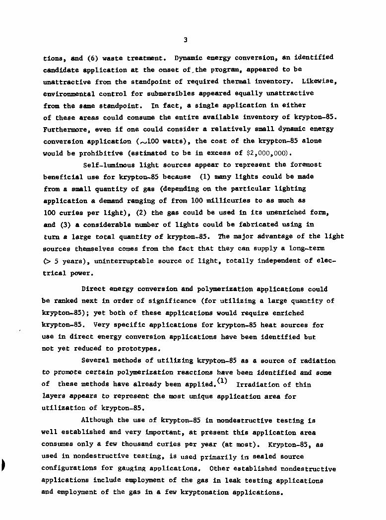
tlons, and (6) waste treatment. Dynamic energy conversion, an identified
candidate application at the onset of,the program, appeared to be
unattractive from the standpoint of required thermal Inventory. Likewise,
environmental control for submerslbles appeared equally unattractive
from the same standpoint. In fact, a single application In either
of these areas could consume the entire available inventory of krypton-85.
Furthermore, even If one could consider a relatively small dynamic energy
conversion application (, 100 watts), the cost of the krypton-85 alone
would be prohibitive (estimated to be in excess of $2,000,000).
Self-luminous light sources appear to represent the foremost
beneficial use for krypton-85 because (1) many lights could be made
from a small quantity of gas (depending on the particular lighting
application a demand ranging of from 100 mllllcurles to as much as
100 curies per light), (2) the gas could be used In its unenrlched form,
and (3) a considerable nimber of lights could be fabricated using In
turn a large total quantity of krypton-85. The major advantage of the light
sources themselves comes from the fact that they can supply a long-term
(> 5 years), uninterruptable source of light, totally independent of elec
trical power.
Direct energy conversion and polymerization applications could
be ranked next in order of significance (for utilizing a large quantity of
krypton-85); yet both of these applications would require enriched
krypton-85. Very specific applications for krypton-85 heat sources for
use in direct energy conversion applications have been identified but
not yet reduced to prototypes.
Several methods of utilizing krypton-85 as a source of radiation
to promote certain polymerization reactions have been identified and some
of these methods have already been applied.^ ^ Irradiation of thin
layers appears to represent the most unique application area for
utilization of krypton-85.
Although the use of krypton-85 in nondestructive testing is
well established and very Important, at present this application area
consumes only a few thousand curies per year (at most). Krypton-85, as
used in nondestructive testing, is used primarily li» sealed source
configurations for gauging .applications. Other established nondestructive
applications Include employment of the gas in leak testing applications
and employment of the gas in a few kryptonation applications.
4
Krypton-85 used in biomedical applications comprises the fifth
beneficial usage in the list. Biomedical applications, to date, have
been of an experimental nature and usually one-of-a-kind in nature. It
is not anticipated that biomedical applications would consume very much
of the available krypton-85; nevertheless, these applications are
important.
Using krypton-85 as a source of dry heat and penetrating
radiation is the remaining consideration for krypton-85. However, no
specific process has yet been identified to utilize the gas.
(
5
RECOMMENDATIONS
Of the total spectrum of applications that have been studied,
at present only small amounts of krypton-85 are being utilized. The
reason is twofold: (1) the price of the gas Is very high (2) and (2) there
is only one (inefficient) enrichment facility (supplying at best 45 percent
enriched kr3^ton-85). TWo other enctmiberances to the utilization of
krypton-85 include (1) lack of good quantitative health physics data,
and (2) lack of quantitative solubility data. Three of the four items
above can be rectified through further research and development. The
price of the gas will have to be lowered to realize any kind of a
market for the krypton-85.
In order of Importance, the authors recommend the following
additional research and development In support of the overall study on
the potentially beneficial uses of krypton-85:
(1) development of an enrichment process which would be more efficient
than the present thermal diffusion process (at Hollfleld National
Laboratory), (2) assessment of the biophysical hazards associated with
krypton-85 (an experimental study), and (3) assessment of the solubility
of krjrpton in various inorganic and organic media. Furthermore, it is
recommended that the decay product, rubldlum-85, be studied from a
materials compatibility standpoint In order to assess the reliability
of krypton-85 containers.
BACKGROUND AND CHARACTERISTICS OF KRYPTON-85
Properties. Collection, and Enrichment
The physical properties of the fission product gas krypton-85
are given in Appendix A. Krypton-85 is generated as a "waste product"
of reactor fuel burn-up and can be recovered along with the other noble gas
fission products via collection from the fuel/cladding dissolution off-
gas stream in a spent fuel reprocessing plant. It is estimated that in the
1980's all krypton effluent from reprocessing plants will have to be held
up and stored for environmental reasons. Thus, krypton should be more
readily available for various applications in the future.
6
There are a nimiber of processes for separating each of the noble
gases from the off-gas stream. Of these processes two separation methods
seem to be most promising: fluorocarbon extraction and cryogenic distilla
tion. The absorption process has been tested on the pilot plant scale
while the cryogenic distillation process has been successfully applied (3 4) in actual operations. ' " Each processing method has the capability of
recovering 99 percent of the gases.
Fission product krypton, as separated from the other fission
product gases, consists (depending on the reactor operating conditions
and the fuel composition and age) mainly of four isotopes: mass 86,
/w50 percent, mass 85, .^4 percent, mass 84, 30 percent, mass 83,
,^14 percent, followed by trace quantities of masses 80 and 78.
Although the krypton-85 can be employed in several applications in
this dilute (unenrlched) form, an enrichment process is necessarily
required to Increase the quantity of krypton-85 in the Isotopic mixture
for many applications. There are four major considerations for enrichment
processes: (1) Calutron, (2) thermal diffusion, (3) plasma centrifuge,
and (4) laser.
A method for electromagnetic separation (the Calutron) of
krypton-85 has been described in Reference 5. ' The method consists of
trapping the energlc particles in the lattice of a moving foil.
Although the process can yield enrichments for krypton-85 in excess of
50 percent, the Calutron can work only with relatively small quantities
of the gas and, thus, is not suitable for enriching large amounts of
krypton-85.
The thermal diffusion process for enriching krypton-85 is the
only "production" process now suitable for processing large amounts of
krypton. As described in Reference 6, the thermal diffusion apparatus
consists of coeixial colimms each with an inner hot wall and an outer cold
wall. In each coltimn the hot wall is separated from the cold wall by a
small distance and the column is arranged in a vertical attitude. The
countercurrent phases consist of an upward-moving layer of hot gas
rising along the hot wall and a downwaird-movlng layer of cold gas falling
along the cold wall. While normal convection keeps these currents moving
continuously in opposite directions, the thermal diffusion creates a |
7
small tendency for the lighter molecules to drift toward the hot region
where they are carried upward while at the same time the heavier molecules
drift toward the cold region where they are carried toward the cold end.
The small separation effect is amplified by the countercurrent flow,
effecting a "large" enrichment which Is realized in the vertical plane.
The thermal diffusion method thus described is at least a working method,
but because it depends upon the mass ratio for achieving enrichment, the
process is quite an Inefficient one for the enrichment of krypton-85.
The plasma centrifuge method, although not fully developed,
appears to be at least as good if not better than the thermal diffusion
method. A nimiber of investigators have studied the process. " -'
The plasma centrifuge works on the principle of separating by mass
difference. In one concept of a plasma centrifuge a "toronado" of
rapidly spinning gases (rotating 5 x 10^ meters/sec) forces molecules
of highest mass to the outside diameter of the centrifuge where they
could be drawn off. Thus, in a two-stage centrifuge configuration
krypton-86 could first be removed from the gas followed by removal of the
krypton-85. Although a great deal of experimentation Is needed to prove
the device's capability, it at least appears to be an attractive, near-
term alternative to the thermal diffusion process.
The laser separation method appears to offer the most promise as
an efficient method of enrichment for krypton-85. Hie reason is that the
laser can be tuned to specific excitation lines unique to the isotope
krypton-85. However, although considerable research in laser separation
techniques^ ^ ^ , no one has reported on a laser separation technique
for the enrichment of kr3T)ton-85. The main reason for no work in the
area of transparent gaseous enrichment (such as for krypton-85) is that
there are no tunable lasers available that operate in the short-wave
length ("hard" ultraviolet) region, a necessary requirement for enrichment
of transparent species.
8
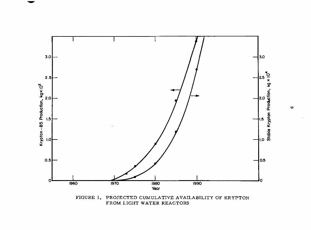
Output by the Nuclear Power Industry
Several references '>"''' provide insight into the future
growth of the nuclear power industry. Although the industry's real
as well as projected output is constantly changing, at least a rough
estimate of the fission product output can be shown. In terms of the
anticipated fission product output, krypton-85 production can also be
estimated and is, therefore, presented in Figure 1. Data for the graph
in Figure 1 come from Reference 24. As one can clearly see, a significant
Inventory of krypton-85 will be available even in the near future.
Appendix B provides further background data relative to the
nuclear power Industry in general.
TECHNICAL ASSESSMENTS
Eight general application areas were addressed in assessing the
potentially beneficial uses for krypton-85. The assessments of each of
the individual areas are presented below. The assessments were made
keeping in mind applications which utilize the unique properties of
kr3rpton-85. Furthermore, attention was given to those uses whereby
large quantities of the fission product could be employed.
Self-Lumlnous Light Sources
The use of nuclear radiation exciting of luminescent materials to
produce visible light has been known for many years. The principle consists
of beta particles (electrons) from the nuclear radiation course striking
and exciting a phosphor causing light to be emitted from the phosphor.
The color of the emitted light is dependent upon the particular phosphor
being used while the brightness of the light is dependent upon the
quantity and strength of the nuclear radiation source.
(
3.0 —
2.5 —
M O X
2.0 —
o 3 •o o m GO
I c o o. >•
<t 1.5 —
0.5
vo
FIGURE 1. PROJECTED CUMULATIVE AVAILABILITY OF KRYPTON FROM LIGHT WATER REACTORS
10
Self-luminous light sources using nuclear radiation (B) to
excite phosphors has particular appeal for such lighting applications
as safety lighting and continuous markering devices. This appeal derives
from several strong advantages over conventional sources of light. The
advantages include:
(1) A light source that is fully self-contained, i.e., no
external power or hookup required
(2) A continuous source of light which provides a uniform
output over an extended period of time (years)
(3) A maintenance-free source of light that will not
"bum out"
(4) A light source which can be used effectively over a
wide temperature range (nominally -100 F to +150 F)
(5) A light source which is uneffected by humidity
(6) A light source free of spark and (electrical) shock
hazard.
Two disadvantages are also associated with the self-lvimlnous
light sources:
(1) A light source which must be licensed by the Nuclear
Regulatory Commission (because it contains radioactive
material)
(2) A light source which is priniarily useful in darkness
(not effective in daylight).
(
11
Today several domestic and foreign conq>anles manufacture self-
luminous light sources. Most familiar are the radium (which requires
charging by a light source) and low-intensity tritium lights on watch
dials and instrument panels. Some of these companies also produce self-
luminous light sources of higher power including those using krypton-85
as the ^-radiation source.
Krypton-85 is a particularly good source of beta particles without 8S
a large gamma energy component (<0.5 percent of total emissions from Kr
are y). Krypton-85's relatively long half-life and inertness also make
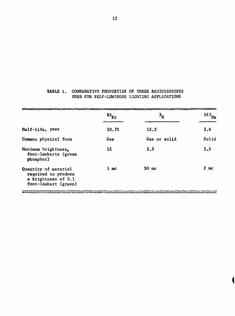
it an attractive candidate for lighting applications. Table 1 gives some
comparisons between krypton-85 (^^Kr), tritium (%), and promethium-147
(1 7pni) isotopes which can be used in self-luminous sources.* It can
be seen from Table 1 that krypton-85 far surpasses the other two in its
ability to excite phosphors.
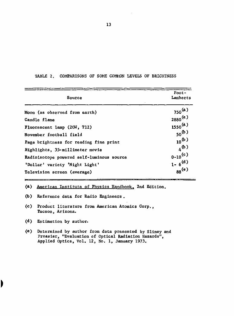
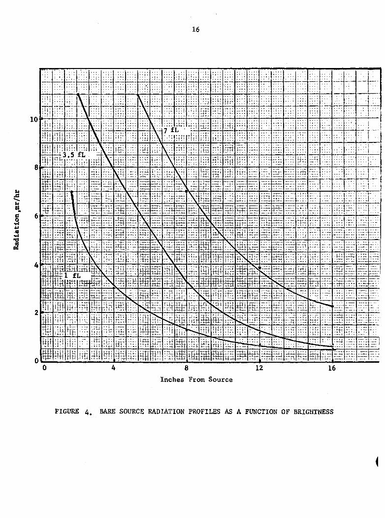
Shown in Table 2 is a list of luminescing qualities of various
common-known sources of light. It can be seen, then, from this table that
krypton-85 can be used not only in applications for self-luminous indicator-
type lights but also for area illumination as well, in fact, at least one
domestic supplier is now producing krypton-85 powered light sources (mainly
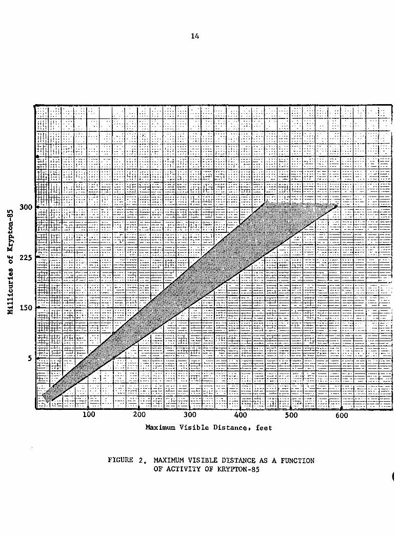
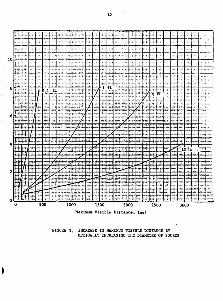
for indicator-type applications). Figures 2, 3, and 4 present data that
are presented in product literature of American Atomics Corporation, Tucson,
Arizona. Comparing the brightness to the quantity and then to the activity
levels one can get an idea of the relative biological exposure that can
be expected from a given krypton-85 self-luminous light source. Also,
for applications where llltmilnatlon Is the prime concern, the number of
light sources that could be deployed to accoiiq>llsh the necessary llltimination
will be limited by the ability to shield (biological) the respective krypton-
85 sources.
* From product literature of American Atomics Corporation, Tucson, Arizona.
12
TABLE 1. COMPARATIVE PROPERTIES OF THREE RADIOISOTOPES USED FOR SELF-LUMINOUS LIGHTING APPLICATIONS
Half-life, year
Common physical form
Maximum brightness, foot-lamberts (green phosphor)
8\r
10.75
Gas
12
h
12.3
Gas or solid
2.5
l^^Pm
2.6
Solid
2.5
Quantity of material required to produce a brightness of 0.1 foot-lambert (green)
1 mc 50 mc 2 mc
13
TABLE 2. COMPARISONS OF SOME COMMON LEVELS OF BRIGHTNESS
Foot-Source Lamberts
Moon (as observed from earth)
Candle flame
Fluorescent lamp (20W, T12)
November football field
Page brightness for reading fine print
Highlights, 35-millimeter movie
Radioisotope powered self-luminous source
'Dollar' variety 'Night Light'
Television screen (average)
(a) American Institute of Physics Handbook. 2nd Edition.
(b) Reference data for Radio Engineers .
(c) Product literature from American Atomics Corp., Tucson, Arizona.
(d) Estimation by author.
(e) Determined by author from data presented by Sliney and Freasier, "Evaluation of Optical Radiation Hazards", Applied Optics, Vol. 12, No. 1, January 1973.
750^^ >
2880^°'
50* >
lO*) 40-)
1- 6^'^
88'"
14
300
225 •'
150 *
200 300 400 500
Maximum Visible Distance* feet
600
FIGURE 2. MAXIMUM VISIBLE DISTANCE AS A FUNCTION
OF ACTIVITY OF KRYPTON-85
I
15
^
;;•
n.1!
i i'.
ft f ^ i
'1 4-1
i
4 I
4 •1 . . -J
-
oil 0
I ' . '..'..
','. I '. '.
•4
]-. ir^:
: . . • : • ; . : ' :
r: ;:"::
X- i i i :
b :f|i 4-1" 11 i i
i?fri-
^M wm
•n -"-'/
4 f •+.t-
' • ' . ' • ' .
: - • • • •
: r :- :
H^:
,..*.. ..
;:rr-?
t
i /k;
^E*i.;. • - : /
- / : TXIJ.
/H'
m
±trt
r t t t
P i V * ^
m
. - 4 - - . .
i t i i
r jx:
rr.:
•r-*-r^
ffir
r ^
^
itr:
5(
Hf:-
;: :•
0 .1
:•::':
-.'•'T:
-A-t—
• ^ : '
• . - H .
rrr i ;
• - —
•fr:;'
' • / ' .
)0
•::r:-
' : : :
: • ' "
f l
::f--
: ~ ;
-~:::
::£': r ~
rl.-:
i i f t
1 .rra
• ^
.:.rl:
-r-'-
; n ;
::::'
' : : : ' •
J ;
^::::'
;rir
.'fr,-
:i]5' Ir:: ~+. . .
#
rn±r * — T - (
Tt!-:.'
-SU
- —
• ' : : :
•iil —»-t—
rErf
—»-,-?-
. - f - f j -
I'Ca."
-.'-TT
r^i—
r t t ;
^
I--:;:;:
••-§
10
-r—
it;. .'. ;
V-r.
.-::
'-•~d
Z T : : .
v::':
-r:H
.•±-.
r.;z~r.
I S
i /_w^-
1T^
^
" X T
• I - - ! — • • • -
00
• ~
;:-•:
::.::
: : ~
' - • • '
r:r!
ZX!i!
i r r n
p fe^
•::z-i
1 rrrrn
5 ^
T=? -T-i'lTC
: : - -
;f;: : : : •
:': •>
:."":::
: : r
: : : . .
y fe
I'Hf " ^^
—t-r . -
- . - ( • • * .
14--
• r - T
-r*r~
: ™ -
: : : :
::: ':
: i:\
i:::
Pi M :.-::
-Xi:
• ~ '
— -
• xr
• p ' - -
3 ^
STr
. ' f
rfrr
15
: : : :
• • r '
. . • , ;
• r — •
L 1 T 1
rZ-
•iir --f—.
H£E
- f — . - . -
:TC
1= • * " f
^
• • - ? — . •
nrz • • • | : - t -
-Z^^t
00
: : ; :
::.:"
r i i '
' ::::
fL.
•*i-. .
•31
T--:r:
tii-.
uri^i. .....;-.
m •rrt:
. rc i -Li-Tl ' " ' i •
:*r.T_" --IT
f.-l
. i i m
; : : :
n iH":
r::f:.
HiJ
T^ »^
sz~ •j^z
w • —.•-:• 4
T ' ' '
4±il
• ^ r rfti
i S r-. t-t-
..^»:.
k;i TI;.:
;.:::
rri.:
—:-"•
?
^ -
-frr
J-l-U-
b i t ;
^ f
- t p : t rn ;
• •H '
t f ]
20
' : : ;
*. ,
i;H :'::-
HT:
rhir
~ T T
5 ^
r - -."•_r
' - Z
.-_-_,.
:n~:
:rrH:
-;-;—-::xtr
— t - ^
•rift:
00
' • . : ' . ' .
'::':'.
•::r.
:H:
"HT"
•-:i.r
7<^
i
—^:
xrr
"Tn
i l i l
- . 1 — ; —
xnn. T : - ^
i-"zt-*'
€ : •
' • " • •
M:
: : :•
: ::.:
.•':.!-
•if;
^ i .•.•.;x
:fr.r —
- + - -
-frr
rixi--
Tx;,'
• - r r ' -
Txr :
i4X" t r - :
•• r-—:-
1 *'
: : : :
::i:
••:-
'.•.\:
:::.:
: ; : :
> ; : : .
H:;
E-f:
— : .ix;.:
^
-4—
1 XCX
i ^ :
tttr
- T * •
25
•; : .
•;^::
f".::
fL"
IE-; ^TT-T
-xx:.
- ^ ^ - t -
n : p
xr;:. _::;X
00
:;: :
':-.•-:
: ; T ;
x:-
ifr:
1 3 *~" •
i ~
a?
"" • *— »
•in:::
rtr::
. - . :
:•':.
^ H
: - : :
:"- '
."rx
x:x-
3r .
X X X
."iin_r.
x ; ^ ^rTx
HE
"mcr
5x? .xK
7 : —
iU^ ix:
:x:i
x3
Ex
-xrx
'—::
EE
?P - 1
"fm* -
EE
i;E:-
^EE
30
-—7"
.' r 11
:E::
liE :E:
E:.
xE
:Ex
EE
n^rr
D IL
rrrr-
•ibx
- j . i , . .
- -
• ' - X X
00
T^*"
——
.
- : : :
; x :
:E:
: x :
• - : . . ' :
.Ex-
X X
Ex
Ex
xx:
- —
~z
—
' ' ' •
1 3
E 3
'—""•"
t •
' . . ', '.-
3 ; . x J
X X t . X »
. . . . J
. 1 X X - . •*
3 - X - "
. x . x : :
EE:
- X . : X
. . .
_ . . t .
.XX .Ex :
— - r — • ]
t *
'; -__^ \"~"— X . X J , : -
Maximum Visible Distance, feet
FIGURE 3. INCREASE IN MAXIMUM VISIBLE DISTANCE BY
OPTICALLY INCREASING THE DIAMETER OF SOURCE
16
—:-
[T^TT
1 i 1' ^
nil t i i i Ui i
m m
[.'Xi;
m p E r' l"*
P pi
m m m
r l j i 1 n ' '
m m W
_ : : :
" E
-.' i.: . 1 :
:tl;
i l l ' '
iHt
.HT x3.'
iEl
•'E
; i 3 ,-i-i:x rtxr-
;-'if W W HU
m ' -':1
-iiE-I'U-X
^W
. " !
: ; • •
. . i .
• ' ; •
.5
. J - , - .
Eii
\ \
-T;' \
itx':. •^-^~f••••
:Xcr
liiii I f
w. Bir
m wv. rlfi
'..'.'
. ' y.
\ \
: • ; :
• - t •
:::J fL
• j f"
• 'h : :;
X.C
:Et
V • -
3 ; -3a
iiE
•?E
i *'-*t'
' ' 1 ••
^ 1^ .
, . , . , . . 1 ,
1 - I I
S^i
A i i ^
mi "It" J - . , . .
;rr:: -f-r-*--
r-tr::
'"" I:.
V 1?S KS
Etf
:gv :^H
E'r: : + T-i
: i r i
Eli
-rE
xi; ! i:
U; \
i - * - . - .
"^;^ - 1 - r *
-~i '
xx-r
ME
[ i ^ EE
- - * - . 1-
•-; X
1.3 1 .--1+-+
:HE
ix !.' !
::!:
. . f t
;-i X
JE: TTtT.
m h 3 r
r § § 1
ffi:
.-t w-
M EH-
: ^
- 3 '
Htl-
llH
iJE :4lX
r-:i
Ex
! * .r.
s r ?N . .'Z".E'
'3.:
E -
•.:E.:'
-:E-:
EM^
s^-.xS
X : : :
"i *- ju
fii i
i • 11
\ ^
^
:n:. xn
itif v..!-.;.
•XXC
• X -
--... ^
r - . - f - -
:. f-,...
EE
^ ^ -+x3^
xar
:-rH-
• 3 ' +
; : i r i
ilfT
*4 - - 1 — - 1 -
^ ^•f^f
i4 IXIX
xi;.*
SI-
X ; :
• : :
V ^
-J - -
jT *„:
rrt::" E-t-L-.
. 1 - * - * - .
,;xx.
^
s> SR -in—
•1:3-
^ x 3
E-I;
183
•::•
• : ' . '
: ' ! " •
7'f
N^i
^ : ; ; M :
:;.E.
i "-*--
Ett
EE
.—^
• • t 1
ex.::
^ m rB.
:2it J3 -. i - . I-
<<^
•iff
S t
'. *!!
J "* 1 t
L
3 -1- ;-•
^ ;rS
r-r.1 •! t - t *
•.nrt'
E E :
n:x yt :
m ^ :HH:' .3E
13 :
n t p :
^ r • I
| n : i
•t^lr
t m
':::'.
• ; •
: r;;
• .:;
X : !
..1::
' 1 • •
:rE:
n"if Sk —
s .;.....> fE: xat
tEf
En: tEt"
.; x.ij
•v t :^
lit rrtt-
S • f - '
riff
• ! :
• ' t i
•-ft!
X i :
If! i . J I
)- •-
i - i -X : - 1 4
-t :r:"
{ ' r •
ki'Xl
\y. 3 ^
t 3 a 4-tJX IxiV - * - r ! •
B4I
i±f
^ :iXiS
ail
tei ^ 31"
:x:
! t T «
' ' i '
l-l It
11 i-I
. T ' !
-rii:
§\^
^
• u U
Sf" f^
t i t l l
xHf xr:x tr+r
M m %
lEE
t t E "i
IHE
m
'XX
x:^
ri.t:
X i •
. t .
;Ef
• 3 ^
tx.x iX'X
EE
; E" *•' • -*"*-'-
mn--t tt. L . . . .
. ^
n ^ m ;3f'-
-fi i ^ • -i-t
E'd
;!:;
i ; ; :
• : : • :
x';;
•Iti
•E.i
x::t
i"*. : J
tiE
Ef-:
f 3 '
3 :
EE
32 t-4-t i-
v''t BS. iTt-i: tiit -h3 rPf-
trfct
r-i-j :
4 T] i
l i x
- ^
%
::•.':
' : ':'•
. - i. *
- t : •
E:: u::
f'-x
• • : •
* • • - * - .
EEf
X : '
-L..X
3 x
EE EE
: L 3
v '"
xxt:| —E t-tr i r x
:3i
:tE ' ^
'. T. *
3 ^
3 :
. : X.
xft
.3f
'IT^
f3"
•.-. * . r
' . - i- lT.
EE fxl
K-X-I-
;->s tEjr XXX] - — r - ' —
E:f •xE:
><^ l^H
M
X : :
! ::
;:E ' r 1
• * r 1
- . - I i-i-
TE ' i-T^
r t a -
f 3 Ti ; , -
ET:.
XI ".Z
""T
* X J U
f ^ EE XIT::
; • • ; *
rl:: ,-T i 1
•
: ::
t ::
E.x;
xE
:t.x; I ^ * r
:Ex
- x t 3 -r*-."!
,-3
X ' X
:§ Eiri_""
. -14
- M '
• • •
:';;
u: \
1^
::•;: •1 4 - ' f-
• • • • r
; * ir
T:h
• -r •
ES x+i+4-
^ ' ^ l ^
. i .i 3 .
. -4 . 4
"T^
M
; • : .
::x
^'^'
i.;:.-
' •
•:x xE
Ei:
T-E-
Ex.
Ex
;fx
f t ;
: ; : • : -
Ej:: :X*l
t T t :
E3i
x3
4 - 4 -
:xir • 1" ;
.3x t-i-!-;.
- —
•:
': X
- •
: x:
t : :
E x
f E
x-'
E--;
X X
.IA.",
• ~
""^ ,.', r
: : • • ;
'.'''.
•.'-Xt
—
Ert
: E
.xf.
"- r"
X X
x/;:
Ef:
E.:x
f~ EE ::ixr
-•4-ht-l
-irri
....
:x4 » ...
: •..
: X
r : •
':. '-
. X
• • - • •
.4.. -
7-X
3T .XX^:
3 x •13"
iEii J trrr
,Ex
Ex
::3
- ( t ^ :
, • :
. •
• • X
• -
.•.:
-":-:
I
j
1
::x,x.: .
• :
x":x
":x":
fEf
-xx:.
i^i' '.'''-z.
EE"
3 "
E:f .•XX
N M M ^
1
} : - : \
f "x':
E 3
Ex>i -IIT-T
: 3 -
-:.:
f :f'
•• ' X
• _ . - )
X r i
• M l ^
0 4 8 12 16
Inches From Source
FIGURE 4. BARE SOURCE RADIATION PROFILES AS A FUNCTION OF BRIGHTNESS
(
17
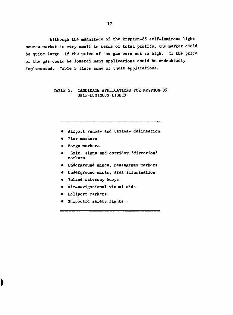
Although the magnitude of the krypton-85 self-luminous light
source market is very small in terms of total profits, the market could
be quite large if the price of the gas were not so high. If the price
of the gas could be lowered many applications could be undoubtedly
implemented. Table 3 lists some of these applications.
TABLE 3. CANDIDATE APPLICATIONS FOR KRYPTON-85 SELF-LUMINOUS LIGHTS
• Airport runway and taxlway delineation
• Pier markers
• Barge markers
• Exit signs and corridor 'direction' markers
• Underground mines, passageway markers
• Underground mines, area illumination
• Inland waterway buoys
• Air-navigational visual aids
• Heliport markers
• Shipboard safety lights
18
The singular most important advantage of using krypton-85 as the
source of radiation is its abundance of beta radiation (it has the
capability of producing four times more light than tritium). Krypton-85
is also an inert gas which means that should the integrity of the light
source ever be broken the gas will not chemically combine with anything.
(The most notable disadvantage of krypton-85 is a gamma energy component
in its total radiation spectrum.) The gamma energy, even though it accounts
for only about 0.5 percent of the total radiation, must be shielded
(using a dense media such as lead) to provide necessary biological protection
for personnel in the vicinity of the light.
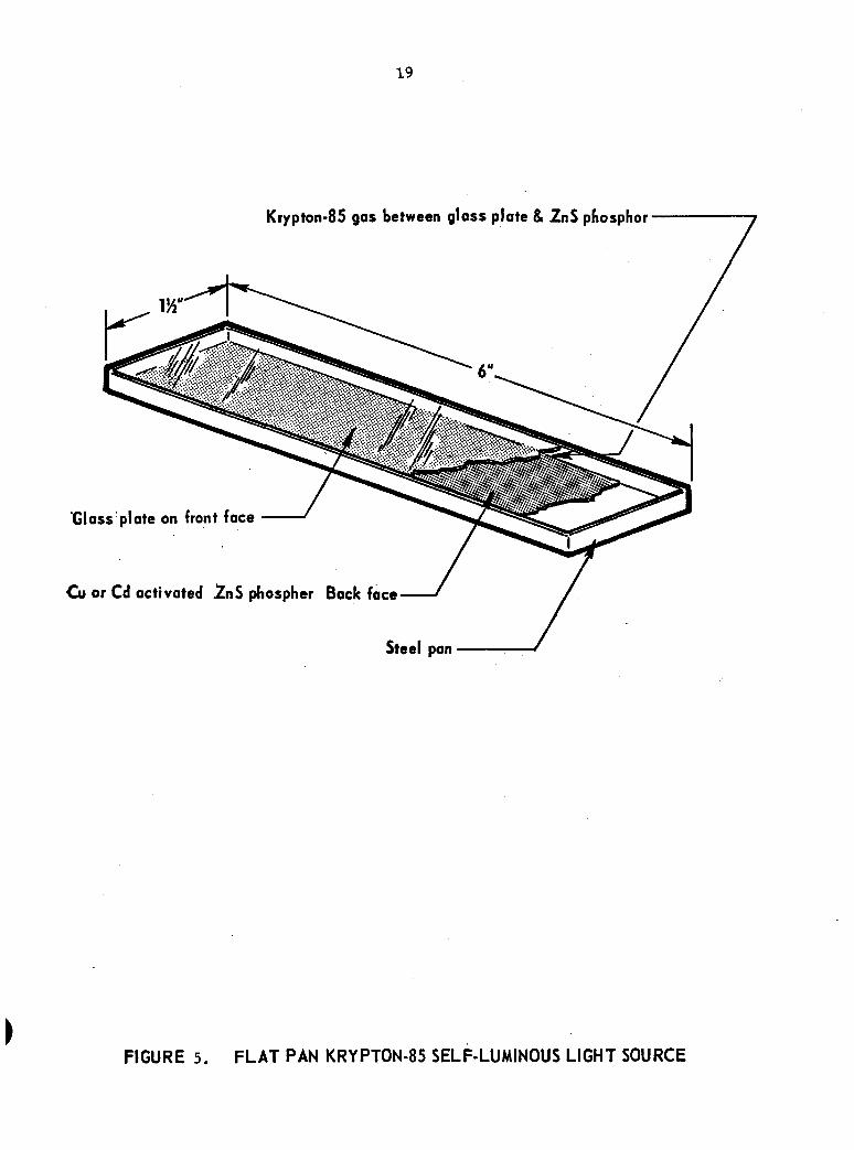
Having the background well in mind, one can then conceive of a
variety of lighting applications for which krypton-85 self-luminous light
sources are particularly unique. Modifications of two distinct configura
tion types are discussed and illustrated below. The two distinct types
are (1) a "direct" radiating type (flat pan) as shown in Figure 5, and
(2) a reflecting type self-luminous light as shown in Figure 6. Based
on these two configuration concepts, then, are a number of applications
as discussed below.
Lights for Underground Mines
Krypton-85-powered, self-luminous light sources can conceivably
be employed for two distinct safety applications: (1) delineation and
(2) area illumination. Lights for both applications would best be
installed in passageways and in coal mines where it is particularly
dangerous to "string" electric lights. In fact, there are no such delineation
or area illumination lights now being employed for either of these purposes
in underground coal mines.
Krypton-85-powered, self-luminous lights used in delineation
applications could provide guidance to miners caught in passageways without
a functioning cap light. Or, the delineation lights could be used to
complement the cap light. Certainly, it would be advantageous for the
miner to know which way the passageway bends or where the passageway roof
is in front of him.
(
19
Krypton-85 gas between glass plate & ZnS phosphor-
Gloss
Cu or
Steel pan
FIGURE 5. FLAT PAN KRYPTON-85 SELF-LUMINOUS LIGHT SOURCE
20
Steel canister
-Glass seal (front face)
Seoled source-
Concave reflecting surface
Krypton-85 gas
ZnS phosphor
Gloss
FIGURE 6. REFLECTOR - TYPE KRYPTON-85 SELF-LUMINOUS LIGHT SOURCE
21
The delineation devices could be quite small and yet quite
effective. An envisioned concept is shown in Figure 7. Note that although
tjrpically the lights would be securely affixed to the passageway walls
and/or roof, they could be moved to new locations by simply unfastening and
then remounting at the new location. Note also that since no electrical
hookup is required, the delineation lights could be considered portable
devices.
With regard to safety, one could consider these delineation
lights as not much of a hazard. Certainly, in their normal mode of opera
tion they are completely contained, emitting little if any radiation
outside of their respective enclosures. Indeed, the worst possible
hazard would involve their deliberate destruction, in which case the gas
(typically less than 200 millicuries) would be released to the atmosphere.
But even if the gas were released, the rate of air flowing through a
passageway is typically quite large and would be effective in removing any
gas. Above all, if a person were to inhale the krypton-85 he would most
likely not retain any of it in his system since it is inert. Several
programs have, in fact, addressed the subject of inhalation of kr3rpton-85
and have shown that it is not particularly harmful.
The low-level-illumination applications for illuminating areas
of the passageways using krypton-85 would involve light sources of
relatively higher intensity and of larger fluorescing areas. A concept
for a low-level illimiinating source using krypton-85 is shown in Figure 8.
The particularly beneficial use of the krypton-85 light source is that it
actually illuminates the passageway floor. The miner, therefore, would
be aided then in knowing what was on the floor since his cap light could
not possibly illuminate everything that he needed to see such as cables,
rails, or other obstacles, to get to where he was going.
The same hazards that are associated with the delineation lights
are also associated with the area illumination lights, namely, the accidental
release of the kr37pton-85 gas. In the case of the area illumination lights,
however, the output of gas per light is much greater (more than 2 curies per
light). Nevertheless, the implementation of such a self-luminous lighting
system could provide much needed safety illumination (where none now exists).
22
Krypton-85 Self-Luminous
Light
FIGURE 7. CONCEPT FOR KRYPTON-85 SELF-LUMINOUS LIGHT SOURCE USED AS A DELINEATION DEVICE IN UNDERGROUND MINES (PASSAGEWAY CROSS-SECTIONAL VIEW SHOWN ABOVE)
23
Stringer Containing the Lights
FIGURE 8. CONCEPT FOR KRYPTON-85 SELF-LUMINOUS LIGHT SOURCE USED AS A FORM OF LOW-LEVEL AREA ILLUMINATION
24
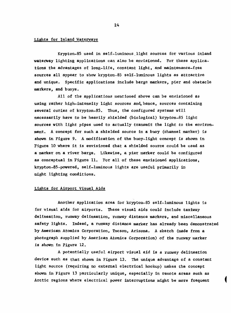
Lights for Inland Waterways
Krypton-85 used in self-luminous.light sources for various inland
waterway lighting applications can also be envisioned. For these applica
tions the advantages of long-life, constant light, and maintenance-free
sources all appear to show krypton-85 self-luminous lights as attractive
and unique. Specific applications include barge markers, pier and obstacle
markers, and buoys.
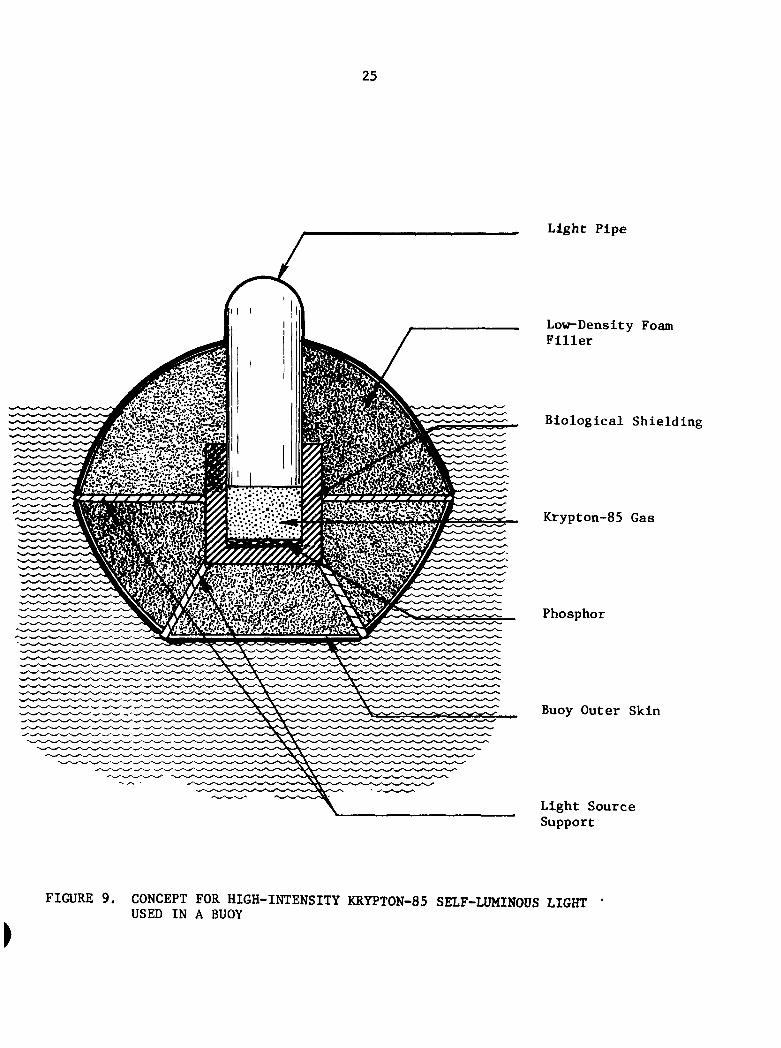
All of the applications mentioned above can be envisioned as
using rather high-intensity light sources and, hence, sources containing
several curies of krj^ton-85. Thus, the configured systems will
necessarily have to be heavily shielded (biological) krypton-85 light
sources with light pipes used to actually transmit the light to the environ
ment. A concept for such a shielded source in a buoy (channel marker) is
shown in Figure 9. A modification of the buoy-light concept is shown in
Figure 10 where it is envisioned that a shielded source could be used as
a marker on a river barge. Likewise, a pier marker could be configured
as conceptual in Figure 11. For all of these envisioned applications,
krypton-85-powered, self-luminous lights are useful primarily in
night lighting conditions.
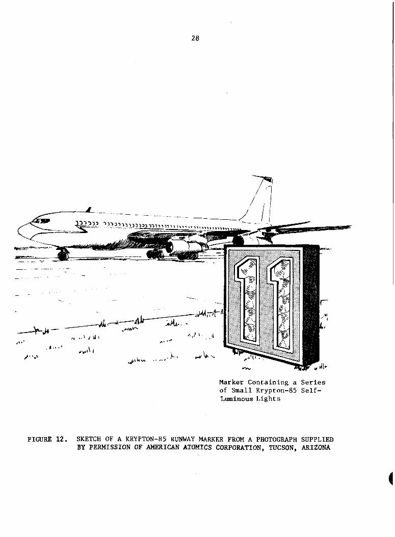
Lights for Airport Visual Aids
Another application area for kr3T)ton-85 self-luminous lights is
for visual aids for airports. These visual aids could include taxiway
delineation, runway delineation, runway distance markers, and miscellaneous
safety lights. Indeed, a runway distance marker has already been demonstrated
by American Atomics Corporation, Tucson, Arizona. A sketch (made from a
photograph supplied by American Atomics Corporation) of the runway marker
is shown in Figure 12.
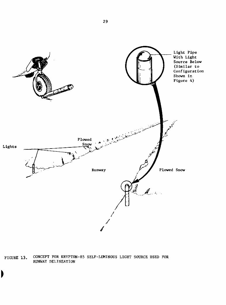
A potentially useful airport visual aid is a runway delineation
device such as that shown in Figure 13. The unique advantage of a constant
light source (requiring no external electrical hookup) makes the concept
shown in Figure 13 particularly unique, especially in remote areas such as
Arctic regions where electrical power interruptions might be more frequent
25
Light Pipe
Low-Density Foam Filler
Biological Shielding
Krypton-85 Gas
Phosphor
Buoy Outer Skin
Light Source Support
FIGURE 9. CONCEPT FOR HIGH-INTENSITY KRYPTON-85 SELF-LUMINOUS LIGHT USED IN A BUOY
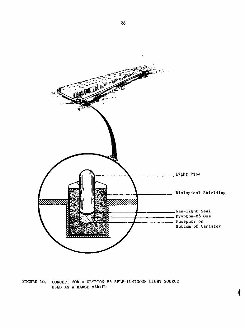
26
Light Pipe
Biological Shielding
Gas-Tight Seal Krypton-85 Gas Phosphor on Bottom of Canister
FIGURE 10. CONCEPT FOR A KRYPTON-85 SELF-LUMINOUS LIGHT SOURCE USED AS A BARGE MARKER
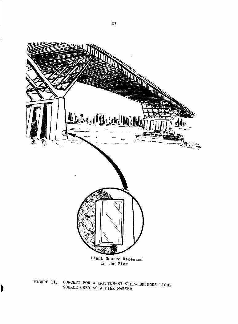
27
Light Source Recessed in the Pier
>
FIGURE 11. CONCEPT FOR A KRYPTON-85 SELF-LUMINOUS LIGHT SOURCE USED AS A PIER MARKER
28
^ ^ i - ^^^^^mm^22:i:!2222l222122l^^^^^^^...,^^
^J*"
i^.T't-^
L,tUl
-,/> -I
Marker Containing a Series of Small Krypton-85 Self-Luminous Lights
FIGURE 12. SKETCH OF A KRYPTON-85 RUNWAY MARKER FROM A PHOTOGRAPH SUPPLIED BY PERMISSION OF AMERICAN ATOMICS CORPORATION, TUCSON, ARIZONA
29
Lights
Plowed Snow
^,->^'
Runway
Light Pipe With Light Source Below (Similar to Configuration Shown in Figure 4)
Plowed Snow
'A X-.
/
/
/
FIGURE 13. CONCEPT FOR KRYPTON-85 SELF-LUMINOUS LIGHT SOURCE USED FOR RUNWAY DELINEATION
30
and especially where snow pileup would render ground-mounted lights
useless.
The single, most important advantage that can be realized
from the krypton-85 self-luminous lights used in visual aids applica
tions is that these lights provide a constant, long lifetime, uninterrupted
source of light (a very critical detail when one considers the possibility
of the lights going out when an aircraft is in the process of landing).
Other Lighting Concepts
There are many other possibilities for lighting using krypton-85
self-luminous light sources. These applications are lumped together here
under a miscellaneous category and include such diverse devices as
(1) beacons for towers, (2) highway traffic signs, (3) shipboard safety
lights, and (4) building corridor (safety) delineation.
Beacons (not approved navigational aids) utilizing krypton-85
self-luminous lights are certainly possible to consider, yet probably
impractical because of the very large amount of krypton-85 gas (greater than
1,000 curies) that would be necessary. The large amount of gas introduces two
problems: (1) a high gamma radiation profile about the source, and (2) a
high rate of phosphor degradation. The gaimna radiation could be shielded
against, but the phosphor damage would present the ultimate limit on the
light (there is very little that can be done to prevent or retard the
damage, and still maintain an all-effective, high-intensity source of
light), Krypton-85 self-luminous lights could not be used for Federal
Aviation Administration navigation systems because the self-luminous lights
do not have the required output (minimum output equivalent to a 116 watts).
At least one highway traffic sign has been installed which used
krypton-85 self-luminous lights. This specific sign enjoyed only marginal
success, however, due to the fact that there were many high-intensity
electric lights in the vicinity of the krypton-85 light. It is envisioned
that many other candidate highway signs illuminated with self-luminous
sources would also experience the same fate as the demonstrator.
Both shipboard safety lighting and building corridor (delineation)
safety lights could very well be considered possible candidate applications
31
for krypton-85 self-luminous lights. Configurations similar to those shown
in Figures 7 and 8 for the mining applications could be tailored for
shipboard as well as building corridor applications. The greatest advantage
for the self-luminous sources is that they provide a constant, long-term
source of light.
Military Applications
Krypton-85 self-luminous lights could be envisioned for the
following specific military-oriented applications: (1) light marker for
missile guidance reference, (2) light beam (breaker) intrusion detection,
(3) markers for air-dropped sensors, (4) remotely deployable aircraft
landing reference (marker), and (5) safety lighting for bunkers and silos.
Several light markers for missile guidance references have, in fact,
already been built and installed for the United States Air Force by f28
American Atomics Corporation.
On the subject of light sources for physical security systems,
krypton-85 self-luminous light sources could be envisioned for use in light-
beam breaker applications such as the one shown in Figure 14. The
unique advantage of the light source is that it requires no external power,
and hence, no electrical hookup or battery supplies. Even though battery
supplies for equivalent electric load capacities can be designed to operate
up to a year, these battery supplies are very sensitive to temperature and
humidity. Therefore, another great advantage for the krypton-85 self-
luminous lights is that they can operate over a temperature range of,
nominally, -100 F to + 150 F with no sensitivity to humidity. Various
adaptations of the system shown in Figure 14 could also be envisioned in
a portable configuration such as might be deployed by a group of men, a
configuration such as that shown in Figure 15.
32
100 meters
Krypton-85 Self-Lumlnous Light
DetectoT:/Transmitter
FIGURE 14. CONCEPT FOR A FIXED-INSTALLATION PHYSICAL PERIMETER SECURITY SYSTEM USING A KRYPTON-85 SELF-LUMINOUS LIGHT SOURCE
33
100 meters
Self-Luminous Light Source
De t ec tor/Trails mi tter
FIGURE 15. CONCEPT FOR A FIELD-INSTALLATION PHYSICAL PERIMETER SECURITY SYSTEM USING KRYPTON-85 SELF-LUMINOUS LIGHT SOURCES
34
Conclusions
In conclusion, there are many applications for self-luminous light
sources including those powered by the fission product gas, krypton-85.
In terms of safety lighting, the krypton-85 self-limiinous lights can provide
an uninterruptible, constant intensity, explosion-free, long-term source
of light, a claim that cannot be made for conventional electric lights. In
terms of runway delineation and other airport visual aids, the advantage of
the uninterruptible light source again appears along with the virtually
maintenance-free aspects of the self-luminous light. Finally, one must
remember that there is, of course, no hookup of wiring for any of the
self-luminous lights (since no external power source is required) making
the installation of these self-luminous light sources quite an easy task.
Technical Assessment of Radioisotope Thermoelectric Generators Involving
Krvpton-85 Heat Sources
Introduction
The design, development, and fabrication of thermoelectric
generators for terrestrial, space, and undersea applications have been well
documented over the past 15 years both in the United States and abroad.
Early thermoelectric generators ranged in electrical output power from
several watts to more than 100 watts. Applications included
auxiliary power for spacecraft (satellite) instruments and transmitters/
receivers, ocean buoy% remote weather stations, detection systems, and
portable auxiliary power for military applications. In more recent years,
the advent of microelectronics has greatly reduced power requirements and
has placed demands for smaller thermoelectric generators—down to several
hundred microwatts in the case of cardiac pacemakers. Surveillance
35
equipment, projectile fuzes, and other applications involving lifetimes
of 5 years or more are also placing increasing demand for thermo
electric generators with output powers ranging from tens of milliwatts
to several watts. However, three principal areas must be addressed
(beside reliability) in the design of thermoelectric generators for
certain selected applications.
• Safety
• Cost
• Specific power (both size and weight).
The cost of RTG's has been influenced principally by the (1) cost
of the encapsulated radioisotope heat source (e.g., plutonium-238 heat
sources), (2) associated design, analysis, and testing of RTG safety
features, and (3) thermoelectric convertor design and fabrication. One
explanation for the high cost of RTG's has been the lack of standardization
in RTG design and fabrication—each new application has t3^ically involved
the development of a totally new concept and configuration, often involving
a new feunlly of thermoelectric materials. Also, few RTG applications to
date (aside from pacemakers) have involved more than tens of units of a
given design.
The third area in RTG design is that of specific power—both in
terms of kilograms/watt and cvcr/vatt. The relatively high thermal power
density and minimal shielding requirements of plutonium-238 make it a
particularly attractive choice of fuel form. Again, the question of
safety in the event of accidental release of plutonium places demands on
the radioisotope containment subsystem and restricts the use of this
type of heat source in certain applications.
The above three design considerations, together with the convertor
reliability, must thus be traded off in a given application in order to
36
satisfy all of the requirements imposed. In the current study of
potentially beneficial uses of krypton-85, BCL has identified the possibility
of using krypton-85 as the radioisotopic heat source for selected RTG
applications in which "safety" is of overriding importance. In certain
selected applications, it must be assumed that the radioisotope may be
released—inadvertently or intentionally. In such an event, a gaseous
heat source (e.g., krypton-85) would be highly desirable since it would
dissipate into the atmosphere, thus minimizing the chances of a localized
radiation hazard or incident. Of course, the penalty of low power density
and relatively energetic gamma radiation associated with krypton-85 must
be paid in the form of a heavier RTG than would be possible with a
plutonlum-fueled RTG. In the discussion which follows, two concepts for
krypton-85-fueled RTG's are described—one having an output power of
1 watt(e) and involving a conventional discrete-element thermoelectric
converter and a second concept featuring an output power of 0.04 watt(e)
and involving a thin-film thermoelectric convertor design.
Description of Selected RTG Concepts
Two design requirements were considered in this conceptual study—
pressure containment of the heat source vessels and shielding to reduce
surface dose rates to less than 200 mRem/hr. The assumptions made in
this conceptual study included
• RTG surface dose rates < 200 mRem/hr
• Output power = 1.0 watt(e) and 0.040 watt (e)
• Total RTG conversion efficiency =2.5 percent (discrete elements converter) and 2.0 percent (thin-film converters)
• Hot-junction temperature = 475 K (202 C)
• Cold-junction temperature =325 K (52 C)
(
37
• 50 percent enriched krypton-85
• Maximum heat source temperature 533 K (260 C)
• Depleted uranium shielding with density = 18.7 g/cm
• Bismuth telluride thermoelectric convertors.
Two RTG concepts have evolved using krjT)ton-85 heat sources and
these are described next. In both of these concepts, a pressurized cylinder
ranging in diameter from 0.635 cm (0,25 in.) to 1.27 cm (0.50 in.) is
envisioned. The size of the overall heat source and the internal working
pressure of the kr3rpton-85 has been selected on the basis of examining the
effect of working pressure on containment wall thickness and, hence, power
density of the heat source. Assuming close packing of right-circular
cylinders, the power density per unit area and unit length, Q, was calculated as
a function of krypton-85 operating pressure at 533 K. These analyses have
indicated that working pressures of up to 6000 psi were required to achieve
satisfactorily high heat source power densities.
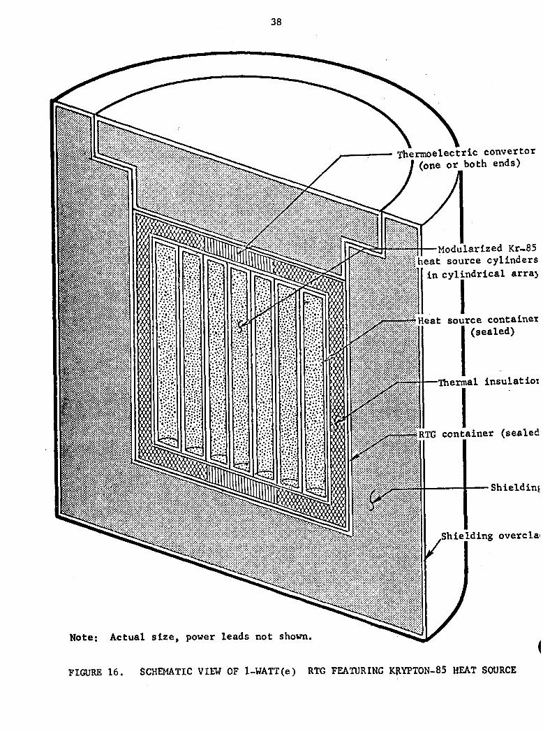
One Watt(e) RTG. One concept for a 1-watt RTG is illustrated in
Figure 16 and features the use of a multiplicity of krypton-85-filled
cylinders (0.635-cm diameter x 6 cm long). These cylinders can either be
individually sealed or be fabricated using a coiled length of tubing. The
externally shielded concept shown in Figure 16 is a cylinder having a
diametral dimension of 13.8 cm (5.4 in.) A conventional bismuth-telluride
thermoelectric convertor is envisioned at two or more locations around the
perimeter of the heat source, providing an output power of nominally 1 watt
at 2 to 6 volts. Although relatively compact, the total weight of this con
vertor will be less than 40 pounds.* Except for the design, fabrication,
and closure of the heat source "modules", this RTG design draws on established
technology. The heat source is envisioned having three separately sealed
enclosures as shown in Figure 16: (1) the modular heat source cylinder,
(2) the heat source container, and (3) the RTG container. Several
variations on this heat source design are also envisioned. For example.
*RTG weights of 15 to 30 pounds are possible in the case of Internally shielded designs.
38
— Thermoelectric convertor e or both ends)
Modularized Kr-85 ieat source cylinders
in cylindrical arraj
Heat source container (sealed)
Thermal insulatioi
RTG container (sealed
Shieldtnj
Shielding overcla
Note: Actual size, power leads not shown.
FIGURE 1 6 . SCHEMATIC VIEW OF 1-WATT(e) RTG FEATURING KllYPTON-85 HEAT SOURCE
39
the heat source might be made by boring an array of holes in a block
and diffusion bonding a "header" plate on one end. This approach would
offer simplicity since only one charging port would be involved. Also,
this approach would offer good heat transfer through the packed array of
heat source "cylinders".
The two-piece shielding subsystem is envisioned as shown in
Figure 16 in order to readily facilitate Insertion and removal of the
RTG unit. This is an important consideration since the RTG unit will
have to be handled remotely once the krypton-85 is introduced.
Forty~Jlilliwatt(e) RTG. A 40-mllllwatt(e) RTG concept is illustrated
in Figure 17 and features the use of a singular cylindrical heat source
capsule (1.3-cm diameter x 5.7 cm long). A thin-film bismuth-telluride
thermoelectric convertor is envisioned comprising 5 to 8 disc-shaped
modules, as illustrated in Figure 18. It is anticipated that such a thin-
film thermoelectric convertor will Involve bismuth-telluride films ranging
in thickness from 0.001 to 0.005 cm and providing an output power of 40
milliwatts (e) at 6 to 10 watts. A similar thin-film thermoelectric con
vertor was recently evaluated at BCL for the U.S. Air Force for f29')
use in projectile proximity fuzes.^ ' It is noteworthy that, even
though the thermal inventory in the heat source for this 40-milliwatt
RTG has decreased by a factor of 20 compared with the 1-watt case,
the required shield thickness has decreased by only a modest amount.
Hence, the specific power of the RTG decreases as we consider RTG's
with decreasing levels of output power. In the present conceptual study,
it appears that the weight of the overall shielded 40-milliwatt(e) RTG .
will range from 8 to 15 pounds (3.8 to 7.0 kilograms)*.
The heat source is envisioned as a thick-wall cylinder con
taining an internal pressure of about 6000 psi. This inner cylinder is
encased in a sealed heat source container and, finally, the unit is
sealed in the overall RTG container (see Figure 17).
*The lower weight applies to internally shielded configurations.
40
11.4 Shielding overclad
•Shielding
Thermal insulatior
Thermoelectric convertor involvir multiple disc modi
Heat source contaj
Unit Krypton-85 heat source cylinc
RTG Container
Note: All dimensions in centimeters, power leads not shown
FIGURE 17. SCHEMATIC MIW OF 40 MILLIWATT (e) RTG FEATURING KRYPTON-85 HEAT SOURCE
Hot Junction s (Aero Heating / Occurs Here)
Hot Straps for Heat Collection
_ Substrate --,
Thermoelectric Elements
Note: All units in inches.
FIGURE 18. DISC-SHAPED THERMOELECTRIC MODULE CONCEPT FEATURING THIN-FILM THERMOELEMENTS
42
One possible design trade-off that may lead to reduced overall
system weight involves internal versus external shielding. In both
example concepts discussed in this report, the external shielding
approach was assumed. However, it is possible to move the shielding closer
to the krypton-85 heat source (i.e., internal shielding approach), thereby
reducing the shield weight based solely on geometrical considerations. The
required shield thickness will of course Increase as we move the shielding
closer to the radiation source. Nevertheless, this trade-off will lead to
substantial weight reductions, particularly in the case of the 1-watt(e)
RTG.
Potential Benefits of Krypton-85 RTG's
Based on the conceptual studies to date, it appears that krypton-85-
powered RTG's offer several advantages over conventional solid radioisotope
fuel forms:
• Minimize hazards associated with accidents which lead to the release of the heat source
• Minimize the chances of "detection" in the event that heat source is purposely or unknowingly opened
• Krypton-85's half-life of 10.7 years provides for useful RTG lifetimes of greater than 5 years.
Potential Limitations of Krypton-85 RTG's
The foregoing conceptual studies have, however, indicated several
potential problem areas or limitations associated with the use of krypton-85
heat sources:
• Require relatively heavy shielding
• Require operation at relatively high pressures involving highly enriched krypton-85 sources
• Limit the specific power of the RTG, particularly at low levels of output power.
43
Conclusions
Preliminary findings during the program are:
• Use of kr}rpton-85 in compact, low-power RTG's requires high containment pressures (2000 to 7000 psi) and/or high krypton-85 enrichment levels (25 to 50 percent).
• Specific weight (lb/watt) of shielded krypton-85 heat sources favors the use of internally shielded configurations (inside thermoelectric convertor and insulation)
• Specific weight (lb/watt) of shielded krypton-85 heat source decreases significantly with increasing thermal inventory.
• Overall weight of 0.04 watt(e) RTG powered by krypton-85 ranges from 4 to 8 pounds (internally shielded).
• Overall weight of 1.0 watt(e) RTG powered by krypton-85 ranges from 15 to 30 pounds (internally shielded).
• Multiple-tube bundle heat source configuration -minimizes hazards associated with failure of single pressure vessel; the penalty in this design is the increased size and weight of the heat source.
The conceptual studies accomplished in this program have not attempted to
fully optimize the design but rather to present generalized design con
figurations. Therefore, given these generalized design criteria and
given a specific application, a more detailed design trade-off effort can
be performed in order to arrive at a more optimum RTG configuration (from
the standpoint of weight, size, and "safety").
Finally, there appears to be at least two noteworthy incentives for
developing kr3^ton-85 RTG's. One incentive follows from the need for an
alternative to storage battery systems (in long-term missions, 5 years or
more) for deployment in critical locations. A second incentive derives
from the fact that krypton-85 is projected to be available in increasing
quantities towards the end of the decade reaching hundreds of kilowatts
(thermal) by the mid-1980's due to anticipated krypton recovery from the
increasing nimiber of operating nuclear reactors and the reprocessing of
their associated fuels.
44
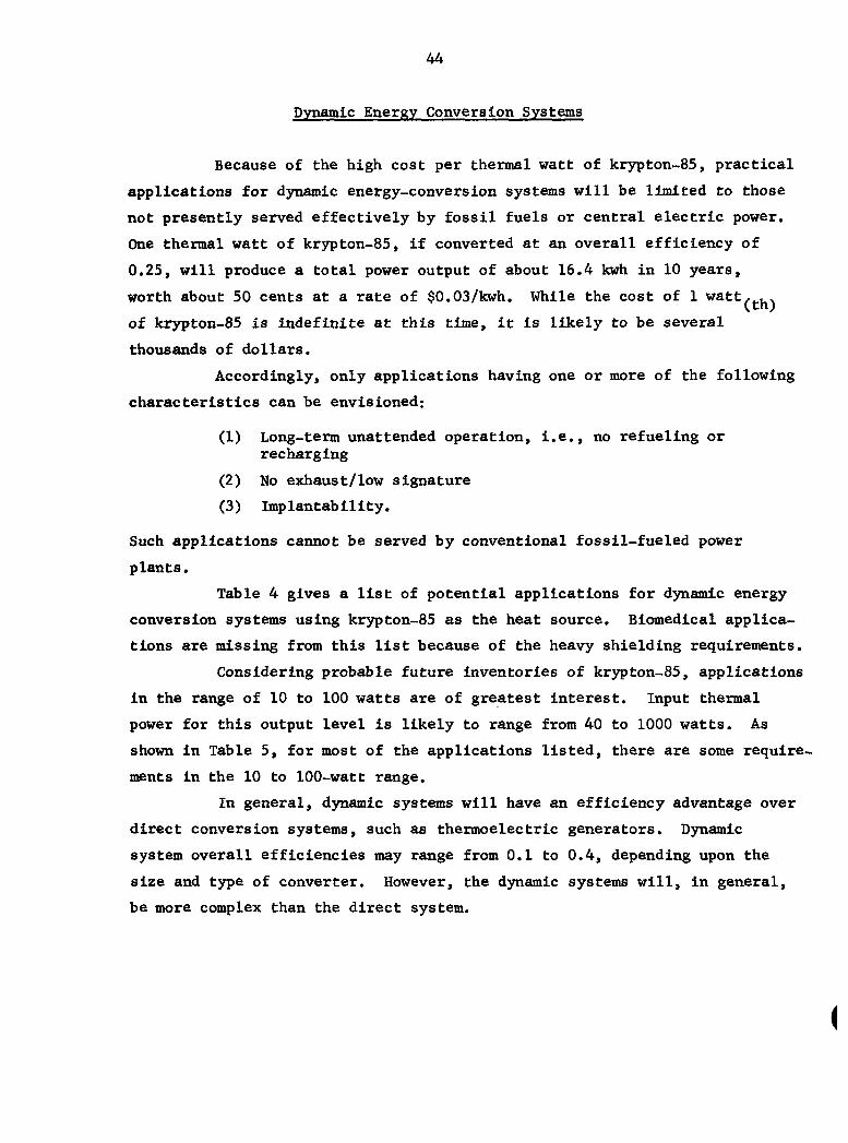
Dynamic Energy Conversion Systems
Because of the high cost per thermal watt of krypton-85, practical
applications for dynamic energy-conversion systems will be limited to those
not presently served effectively by fossil fuels or central electric power.
One thermal watt of kr3^ton-85, if converted at an overall efficiency of
0.25, will produce a total power output of about 16.4 kwh in 10 years,
worth about 50 cents at a rate of $0.03/kwh. While the cost of 1 watt, . .
of krypton-85 is indefinite at this time, it is likely to be several
thousands of dollars.
Accordingly, only applications having one or more of the following
characteristics can be envisioned:
(1) Long-term unattended operation, i.e., no refueling or recharging
(2) No exhaust/low signature
(3) Implantability.
Such applications cannot be served by conventional fossil-fueled power
plants.
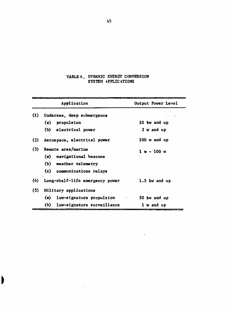
Table 4 gives a list of potential applications for dynamic energy
conversion systems using krypton-85 as the heat source. Biomedical applica
tions are missing from this list because of the heavy shielding requirements.
Considering probable future inventories of krypton-85, applications
in the range of 10 to 100 watts are of greatest interest. Input thermal
power for this output level is likely to range from 40 to 1000 watts. As
shown in Table 5, for most of the applications listed, there are some require
ments in the 10 to 100-watt range.
In general, dynamic systems will have an efficiency advantage over
direct conversion systems, such as thermoelectric generators. Dynamic
system overall efficiencies may range from 0.1 to 0.4, depending upon the
size and type of converter. However, the dynamic systems will, in general,
be more complex than the direct system.
(
45
TABLE 4. DYNAMIC ENERGY CONVERSION SYSTEM APPLICATIONS
Application Output Power Level
(1) Undersea, deep submergence
(a) propulsion 10 kw and up
(b) electrical power 2 w and up
(2) Aerospace, electrical power 100 w and up
(3) Remote area/marine . .^n 1 W - lUU w
(a) navigational beacons
(b) weather telemetry
(c) comaiunications relays (4) Long-shelf-life emergency power 1.5 kw and up
(5) Military applications
(a) low-signature propulsion 50 kw and up
(b) low-signature surveillance 1 w and up
46
Item 5 of Table 4, low-signature military applications, was
listed because of the possible strategic advantage over a conventional
exhaust-producing propulsion system, which has a thermal and chemical
signature. However, the krjT>ton-85 power plant would not be completely
without signature, there being waste-heat rejection from the system
radiator at temperatures up to 100 C.
The krypton-85 d5mamic system would also be free of combustion
noise, but would not be as quiet as a direct energy-conversion system.
Brayton-Cycle Systems
Brayton-cycle energy conversion systems are well suited to a
variety of applications ranging from 10 kw to over 50 mw; applications
in this size range are generally well beyond what can be considered practical
for krypton-85 heat-source applications. Brayton-cycle systems can be
designed for lower outputs, but with some loss in efficiency.
Tip speed is an important parameter in the design of Brayton-
cycle turbomachinery; for low power levels, the wheel diameters are
necessarily small, requiring high rotative speed to maintain tip
velocity. Thus, at some extreme low power level, wheel diameters become
too small and rotative speeds become too high to be practical. Small
turbomachines generally suffer from a high ratio of tip clearance to blade
height which leads to excessive leakage and low efficiency.
Nevertheless, Brayton systems have been designed for as low as
0.5-kw output. Reference 30 describes such a system for a plutonium-238
heat source, which operates at 48,000 rmp with low working fluid pressures
(4.2 psia compressor inlet, 7.7 psia discharge). The working fluid for
this closed-cycle unit is a mixture of xenon and helium having a molecular
weight of 60. The estimated cycle efficiency of this unit is 0.156
compared to about 0.3 for larger units using radioisotope heat sources.
i
47
An interesting feature of the Brayton-cycle system in this
instance is the fact that krypton could be used as the working fluid;
Reference 31 describes experiments with closed-cycle Brayton units operating
with krypton. Alternatively, a Kr-He mixture could be used advantageously,
as are Xe-He mixtures. With some mixture of krypton-85 as the working
fluid, no heat exchanger would be needed to transfer heat to the working
fluid; rathei a fluid reservoir placed between compressor discharge and
turbine inlet would seirve to heat the fluid. Residence time of the fluid
within the Brayton rotating unit is sufficiently small that heat release
within the engine would be negligible.
Unfortunately, the required volume of the krypton reservoir would
be large and not worthy of consideration because of the limited supply of
the gas. Assuming 0.5 kw(e) output and 3.2 kw(th) input (as for the system
described in Reference 1), an inventory of about 5.2 kg of krypton-85
would be needed. At the 0.53 atm turbine discharge pressure, a reservoir 3
volume of 23.6 m would be required with 45 percent enriched krypton-85.
The turbine could be designed to operate at a higher discharge pressure
with an attendant increase in rotative speed and possibly a decrease in
efficiency.
Alternatively, the krypton-85 could be stored in an array of
pressurized tubes which form an effective configuration for heat transfer
to the working fluid, which presumably would not be krjrpton.
The Brayton-cycle units would offer good potential for high
efficiency and long unattended service life, and would be the preferred
choice for most applications above 3 kw; it would be usable in applications
as small as 0.5 kw.
Stirling-Cycle Engines
Stirling engines can be built for power levels ranging from a
few watts to several hundred kilowatts. Small Stirling engines have been
built for biomedical applications (32,33) that developed about 5-w output with
about 40-w thermal input; such units use plutonium-238 as the heat source
48
and experimental units have been run 5000 to 7000 hours without failure. As
previously mentioned, krypton-85 is not a desirable heat source for
biomedical applications at this power level; however, the small Stirling-
engine technology developed for this application would probably be trans-
ferrable to other applications.
Stirling engines have a peculiar design limitation: their
performance is penalized by large void volume in the heat-transfer com
ponents of the engine. Since the krjrpton-85 heat source could be en-
capsuled in tubes of any configuration, a great deal of flexibility in
heater design is afforded, and some operational benefits could result.
Krypton-85 would not be desirable as a Stirling-engine working
fluid, as low-molecular-weight fluids such as hydrogen or helium are
found to be most advantageous.
Rankine-Cycle Engines
Rankine-cycle engines can be built either with piston expanders
or turbine expanders. The Rankine turbine has size limitations analogous
to those of the Brayton turbine, although Reference 34 describes a 7-watt
output Rankine turbine with a 1/2-in.-diameter expander rotating at
200,000 rpm. In one form or another, the Rankine engine can be built
in a virtually unlimited size range.
The cycle fluid, temperatures, and pressures must, of course, be
selected so that the fluid goes through phase transformations in the boiler
and condenser. Water/steam is a commonly used fluid; steam units must be
protected from freezing environments and the expander bearings must generally
be sealed from the water—a design complication. Organic fluids can also
be used; these are limited to moderate peak cycle temperatures (300 to 400 C)
with correspondingly modest thermal efficiencies, but organic fluids can
be selected that will not freeze in normal environments and which are
miscible with lubricants (or have some lubricating properties themselves).
Krypton could not be used as a Rankine-cycle working fluid at normal
temperatures.
49
Rankine-cycle system boilers have no unusual design requirements
that would either favor or prohibit the use of krypton-85 as a heat source.
Presumably, an encapsulating tube array could be designed that would seirve
well as the boiler heating surface.
Conclusions
The cost of krypton-85 per thermal watt is such that it is not
competitive with applications that can be seirved by fossil fuels or, in
general, by solar energy including solar cell arrays for aerospace applica
tions, which can be produced for under $100/thermal watt. Competitive with
other radioisotopes, the cost must be considered on a case-by-case basis.
Although kr}^ton-85 is usable in a Brayton cycle engine, the minimum thermal
requirements would be in the 500-watt to 1-kilowatt class and this is a
rather impractical consideration (either from a cost or quantity basis).
Polymerization
Much work has been done in the past 20 years on the use of
radiation (cy, 3, y* ^'"^^ neutron) to polymerize vinyl monomers and modify
(cross-link, graft) performed polymers. Most of the research reported in
the literature has centered on cobalt-60 y irradiation. Commercial
applications have been relatively few but several important industrial
processes have resulted. These include the use of cobalt-60 y irradiation
for the preparation of methyl iodide, for the manufacture of polymer
impregnated (in situ polymerization of methyl methacrylate) hardwood
parquet flooring, and for some specialty polymer grafting and cross-linking
reactions. Electron beam curing of polyethylene wire and cable jacketing,
indoor and outdoor wood paneling (principally polyester impregnated),
and solvent-free liquid polymer coatings are also commercial realities.
50
Both cobalt-60 y and electron beam 3 Irradiation are capital-
intensive radiation tools. Gamma irradiation is highly penetrating and
requires extensive shielding but allows curing reactions to be carried
out through thick cross sections. Beta irradiation requires sophisticated
and expensive equipment but is nevertheless a good tool for curing or
hardening surface layers or thin cross sections, such as wire jacketing.
Ganna and beta irradiation in general are capable of relatively rapid or
efficient polymerization or cross-linking reactions without requiring the
use of precious heat energy or contaminating organic peroxides.
A potentially useful source of P irradiation that has received (35)
almost no research attention to date is krypton-85. ^ The most unusual
feature of kr3^ton-85 is, of course, the fact that it is a chemically
inert gas. As such it has the following highly unique properties which
should be of very practical benefit in certain specialty polymerization
and polymer modification applications:
(1) Krypton-85 will uniformly fill any confined volume.
(2) Krypton-85 will uniformly reach all exposed surfaces of a complex shape. This is especially important with convoluted or baffled surfaces.
(3) Absorption into some surfaces to effect desirable results at controlled depths is possible.
(4) As a gas, krypton-85 can be pressurized to control the effective radiation dose at surfaces.
(5) Krypton-85 can be uniformly dissolved in liquids or solids to effect polymerizations throughout a reaction mixture.
(6) Krypton-85 forms clathrate compounds with such chemicals as urea and can be absorbed on charcoal. Similar complexes with specially designed molecular sieves should also be possible. (These capabilities should offer unique reaction possibilities.)
These unique features of krypton-85 were used as the basis for formulating
new potentially useful concepts for beneficial uses of krypton-85.
51
Conclusions
In conclusion, a number of unique applications can be envisioned
for using krypton-85 to promote polymerization reactions. In-depth
analysis of the unique properties of krypton-85 vis-a-vis the concepts
already formulated, incorporating a wider range of polymer technology
than was possible during this program, should provide many additional
new concepts. At any rate it appears that krypton-85 can be utilized for
polymerization, probably in its enriched form.
Referring to the properties listed in the above section, one
can identify specific applications as enumerated below.
Concepts Based on Property 1
(1) Use krypton-85 contained in thin-wall tubes as a fixed energy source
to replace or complement UV or electron-beam sources for industrial
curing processes. A material useful as a container for the krypton-85
which would allow penetration of the electrons would need to be
identified. This may be a difficult goal to achieve.
(2) Polymerize gaseous monomers such as ethylene to obtain high-purity
polymers for electrical applications requiring especially low
dielectric loss. Property 4 would also be important in this
concept.
Concepts Based on Property 2
(1) Solvent free liquid polymer coatings (UV curable paints and inks,
fusible powder coatings) can be cured in normally inaccessible areas
without the use of heat, UV or electron beam guns. This could be
particularly important where pigmented coatings, such as automotive
paints, are involved. Formulations based on commercially available
UV or electron beam curable vehicles should be usable.
52
Cross link (i.e., surface barrier) or graft to the interior surfaces
of hollow fibers. Such fibers are the heart of the favored designs
for kidney dialysis machines and in reverse osmosis devices for
desalination of seawater. Properties 3 and 4 could also play
a key role in studies in this area. The key to successful dialysis
in these machines is a properly structured surface layer on the dialysis
membrane for rejection of such chemicals as urea or NaCl while allowing
free passage of water. Carefully controlled cross linking and/or
grafting reactions on the inaccessible inner surfaces of the hollow
fibers is a necessity. Kr3rpton-85 offers the possibility of
accomplishing desirable reactions on preformed bundles of hollow
fibers, thus being a very efficient process.
Similarly, the outside of polymeric or polymer coated glass optical
fibers (light pipes) could be very uniformly cross-linked or grafted.
Carefully controlled refractive index increase at the surface is
required for efficient light transmission. The proper modifications of
the surface might be done very efficiently using krypton-85. Success
ful modifications here could be very important in energy or information
transfer applications. For example, laser transmission over long
distance with controlled light energy loss is the key to optical trans
mission systems based on this principle. Again Properties 3 and
4 could also be very important in achieving the desired surface
modifications.
The surface or entire cross section of fibers traveling through a
krypton-85-filled chamber could be cross linked or grafted to effect
desirable changes (e.g., strength, strength at elevated temperature,
reduce static charge problem, etc). This idea would appear to be
applicable right at the spinnerette of a fiber-forming operation. The
many multifilaments coming out could immediately enter a krypton-85
filled chaniber and could then be twisted into yam. Again Properties 3
and 4 might be applicable.
53
Concepts Based on Properties 5 and 6
(1) Krypton-85, complexed or absorbed as described in Property Number 6,
should be usable as a unique, flexible radiation source when dispersed
in liquid media, or as a fluidized bed. The latter idea has particular
attraction as a possible way to use gaseous krypton-85 in a more
controlled manner, yet possibly still making use of fluidity properties
to uniformly cross link or graft onto polymer surfaces of irregularly
shaped objects.
54
Nondestructive Testing
The properties of krypton-85 in the gaseous form, as well as in
the kryptonates, makes the isotope well suited for several nondestructive
testing applications as well as related sensing applications (that are
not truly nondestructive testing). Thus faij krypton-85 in gaseous form
has been (and is being) used in the following applications
• Weight gauges
• Thickness gauges
• Leak detection
• Fluid flow tracing
• Flow detection
• Miscellaneous.
In kryptonate (krj^ton-impregnated materials) form, the radio
isotope has been demonstrated effective in flow detection and thermal
mapping applications. References 36 through 47 provide detailed descriptions
of various nondestructive testing applications using krypton-85.
Gaufiing
Krypton-85 in the unenriched form (/ 4 to 6 percent) as well as
in its enriched form (up to 40 percent) is particularly well suited for
weight and thickness gauges. The krypton-85 provides a uniform, stable,
long-term source of 3 energy for accurate thickness and weight measure
ments. The kr3T)ton-85 sealed source is also unaffected by extremes in
temperature or humidity and, of course, is fully self-contained.
Most applications involve use In manufacturing process control
and make use of two classes of gauges: a transmission type and a back-
scatter type. The transmission gauge uses a radioisotope sealed source
and detector combination with the material to be measured (weight or
thickness) running between the source and detector. Variances in the
material are recorded by the variance in radiation intensity as seen by
55
the detector and the detector then sends a signal to the process equipment
for appropriate action (or no action). Transmission gauging systems are
typically employed in the paper, plastics, and rubber industry with sealed
sources containing from 500 millicuries to a few curies of krypton-85
(per source).
There are also beta energy backscatter gauges which have been
reported in the literature.' ' In this configuration the reflectance of
the beta energy is measured, indicating such things as surface hardness.
Industry acceptance is, however, unsubstantiated.
It is difficult to say just what the total consumption of
krypton-85 for these gauges is, since the data is proprietary to the
respective gauge vendors; however, it is probably safe to say that this
particularly beneficial use of krypton-85 demands several thousand curies
per year.
Leak Detection and Fluid Flow Tracing
Krypton-85 gas used as a media in leak and flow detection has
seen limited use, mostly as a part of research programs. However, the
electronics industry has used krypton-85 quite heavily^ ' in guaranteeing
the integrity of hermetically sealed components. Cost and sensitivity are
probably the most important advantages for these krypton-85 processes. The
cost of the krypton-85 (unenriched) is of particular advantage as opposed
to the cost of a mass spectrometer system. The sensitivity of the process
(using kr3T)ton-85) is probably unparalleled.
The leak detection procedure involves "soaking" a batch of com
ponents in krypton-85 at 100 to 120 psi for 2 to 16 hours. ' During the
period, the leaky components are partially filled with the kr3T)ton-85 gas.
Following the pressurization, the krypton-85 gas is pumped back into a
containment reservoir (for later use). The partial vacuum created during
the pumping-off operation tends to clean the exteriors of the components.
An intermediate helium leak detection method can then be used to reject
components with larger leaks (since the pimiping-off operation will remove
56
most of the krypton-85 from components with large leaks). Finally,
inspection of the components involves using a scintillation counter to
screen out defective components.
It is again difficult to estimate the total consumption of
krypton-85 in leak detection. The process allows recovery of nearly all
of the original gas, and so the particular process really requires only
an Initial investment of krypton-85 gas.
The use of krypton-85 as a tracer to observe fluid flow and fluid
mixing has not been widely reported. This lack of literature references
may be due to lack of experimentation or lack of good results. Yet there
do seem to be potentially beneficial uses for the krypton-85 gas. In
fluid flow measuring applications, the krypton-85 could be used to indicate
choking through a network or even leaks. In fluid mixing operations, the
radioisotope could be used to indicate the rate and degree of mixing as well
as the location of "true" mixing within a given confluence.
Flaw Detection and Thermal Mapping
Nondestructive testing using kryptonated (krypton-impregnated
materials) has received wide attention in the past.^^'»^°»^^) At least one
kryptonation process is presently being used. The general process is
useful in detection of material flaws.
The kryptonation process involves impregnation of a given
material with krypton-85. Since krypton-85 is an inert gas, its incorporation
into the host material crystal lattice will not physically or chemically
affect the host material. However, the gas (krypton) will be released by
physical or chemical action on the host crystal lattice, thus permitting
its application as a tracer atom to study various parameters affecting
the crystal lattice itself.
Krypton-85 can be forced into a material crystal lattice via (39) two methods ': (1) ion bombardment and (2) pressurization. In general,
whatever the method, all kryptonates can be characterized as having the
same properties. First, they can be prepared at various levels of activity
57
with the penetration depth simply controlled via the specific experimental
technique used. Second, the kryptonates are very stable with time at
room temperature. Third, any process (chemical or physical) that
disturbs the host material will result in some loss of activity. And
last, a given fractional loss of krypton-85 in a krjrptonate occurs upon
heating of the host material at constant temperature. Some disagreement
exists, however, as to whether the outgassing krypton from the host material
does, in fact, obey the classical diffusion laws.^ y^^6)
Kryptonation techniques have been investigated for use in
determining material surface conditions, i.e., wear patterns and flaw
detection. The process is quite sensitive, and probably for that reason
has enjoyed limited acceptance.
Kryptonation of turbine blades for thermal mapping has, at least
at one facility, been proven very successful. The process has
been implemented to verify the conditions of materials in gas turbine
power plants which have experienced overtemperature excursions. The
power plant materials (the turbine blades, primarily) are subjected
to krypton-85 impregnation. Following the kryptonation the materials
are djmamlcally rotated and thermally stressed. This process then
causes release of the krypton-85 which is, in tuim, measured via counting
techniques which yields a quantitative measure of the material conditions.
The reported results of the "thermal mapping" kryptonation (46 47)
application * ' show that the materials exhibiting a low level of krypton-85
containment are most likely to yield short-term overtemperature indications.
Sensitivity of the mapping technique can be controlled through the
Impregnat ion parame ters.
Miscellaneous Applications
Krypton-85 has also been applied to various other sensing type
applications. These include (1) chemical sensors for the detection of (37) (37)
hydrogen , (2) gamma communications ', (3) propellant level (38)
indicator , (4) a passive device for determining relative rotation, (5) an atmospheric tracer in defining puff dimensions and transport
58
speed' ', (6) a helicopter lift indicator ' \ (7) a detection method (US') for automobile-exhaust pollutants'- '', and (8) a lightning rod. Most of
these applications are one-of-a-kind or only experimental in nature; yet
they are worthy of note.
Conclusions
Indeed, krypton-85 has already been identified as a very
important component in a number of nondestructive testing applications.
Many of these applications have been well developed, especially the
sealed source gauging, while a few of the others are one-of-a-kind
operations. However, as a general statement,nondestructive testing
applications consume a relatively small (a few thousand curies per year)
portion of the total available inventory of krypton-85.
59
Biomedical Applications
The use of radioactive gases, including krypton-85, to monitor the
flow of biological fluids, has been the subject of many research investiga
tions during the past 15 years. ~ Three conclusions can be drawn from
the published literature in this technology: (1) there is a paucity of
information concerning the toxicity and dosage of krypton-85 in model
studies, (2) the work on monitoring biological fluids using radioactive
-gases continues to be of an experimental nature, and (3) scarcity of informa
tion concerning the consumption of krypton-85 suggests that the consumption
from krypton-85 sources will only be a very minor draw upon the total supply.
Nevertheless, the potentially beneficial use of (or particular lack of using)
krypton is assessed below. Except for minor differences in the solubilities
of krypton-85 and xenon-133, for which little or no quantitative data exist,
it would seem that the xenon-133 would be the better choice of isotopes
because of its much shorter half-life (22.4 hours).^
Toxicity data for krypton-85 is confined to preliminary investiga
tions with inhaled krypton-85 in animals. It is probably because of lack
of data that many more experiments have not been performed or that other
chemicals and Isotopes have been used (for which more data exist) in the
place of krypton-85 and xenon-133. Retention in body organs (animals) has
not been fully qualified, although several investigators have reported
quantitative values from a few specific experiments. Low solubility of
krypton-85 in tissue and blood have been reported, yet full assessment
(at least as reported in the literature) seems incomplete. It does appear
from reading the literature that the various investigators agree that the
lung is a very efficient filter and that the lungs and airways must be
considered the critical organ receiving the highest exposure from in
advertent release of krypton-85. Reference 59, for instance, reports that
for short-term exposure of 1 minute and long-term exposure of several
hours to a cloud of krypton-85, the absorbed dose by tissue represented
about 1 percent of the dose received from external radiation (gamma and
bremsstrahlung).
60
Conclusions
In regards to body fluids, krypton-85 has been used in measuring
(1) cerebral blood flow, (2) cutaneous blood flow, (3) muscle blood flow,
(4) renal blood flow, (5) nitral blood flow, and (6) intestinal blood flow.
In all cases, the work was experimental in nature and quite limited in
scope. Even if krypton-85 was used on a broad scale as a "routine" clinical
fluid-tracer method, only small quantities would be consumed. Furthermore,
in many of the literature references, xenon-133 appears to work as well as
the kr5T)ton-85.
(
61
Waste Treatment
Reactions initiated by ionizing radiation from various isotopes
have been employed or proposed for the treatment of wastes from human
activity and from manufacturing. This application of process radiation
has vast potential, yet is one of the most controversial because of con
flicting reports in the literature. Radionuclide sources producing high
levels of beta O ) or gamma (y), notably cobalt-60 and cesium-137, have
been used or proposed for such operations. The scale of demonstration
operations has been limited to pilot facilities. Other processes have
been limited to bench-scale or laboratory-scale levels wherein the
proof-of-principle was demonstrated.
Typical studies relating to wastewater treatment employing
ionizing radiation have been complied in reviews on process radiation f78-92^
development. ' Primarily, these reviews relate to sewage treatment
by radiation to promote improved sedimentation, conversion of organic
materials resistant to bacterial attack to those that are, and the destruction
of bacteria. Treatment of industrial waste waters (by ionizing radiation)
from cotton-textile-finishing mills, Kraft-paper mill^ and wool mills at
high oxygen or air pressures was demonstrated to be effective for the
reduction of biological oxygen demand (BOD), chemical oxygen demand (COD),
and removal of colorants and dyes. The evaluation of the
effectiveness of the processes was based on the reduction of these para
meters and the improved characteristics of the wastewater that result.
Disinfection of pathogenic microorganisms in sewage and improved sedimenta
tion are added benefits obtained by the use of ionization radiation in
sewage treatment. Besides the degradation of biologically refractory
organic substances, such as phenol, parathion, phenylmercuric acetate,
etc., radiation has been demonstrated to be effective in the destruction
of cyanide ion in electroplating wastes and enhancing the removal of iron
from acid mine drainage by limestone neutralization.
62
The economics related to such concepts have also been considered,
especially for sewage treatment plants in the mi11ion-gallon-per-day
capacity range. Figure 19 shows the quantity of cobalt-60 that could be
purchased for different treatment costs (the price of cobalt-60 in 1969
was about $0.35/Ci, a more optimistic price then was $0.10/C1.^ ^
The radionuclides cobalt-60 and cesium-137 served as the radiation
sources in these operations. The radiation characteristics of the two
are such that they provide P and y radiation. The average energy of the P
is such that the half-depth of penetration in water is 4 cm or less.
Therefore, it is the gamma radiation with ability to penetrate materials that
provides the energy for chemical change through bond scission (homolytic
splitting) or ionization.
Krypton-85 radiation characteristics are similar to those of cobalt-60
and cesiiun-137. It is a good beta emitter; however, the gamma is of low
yield, 0.41 percent, and does not provide the high yield apparently
required for large-scale operations using shield sources. In another
limiting sense, the density of the confined gas cannot approach those
of the metals (e.g., at standard temperature and pressure the atom con-" 1 9 3
centration for krypton is about 3 x 10 atoms/cm, while for cesium it is 21 22 3
8 X 10 and for cobalt it is 9 x 10 atoms/cm ). In addition, isotopic
concentration of krjrpton-SS of 6 percent can be obtained easily, while
45 percent can be obtained only with great difficulty (reference cited
earlier).
Krypton-85 has properties, however, that make it attractive as
a radiation source. For one, the radiation level at the interface between
the container for the gas and the reaction media can be controlled by the
pressure or concentration of krypton-85 in the container system. This
provides an easy means of modulating the amount of radiation being received
by the medium.
Another property is that it is essentially chemically inert. As
such, it might be used as an internal radiation source wherein it is
intimately mixed with a gaseous media. In aqueous systems, it exhibits low
(
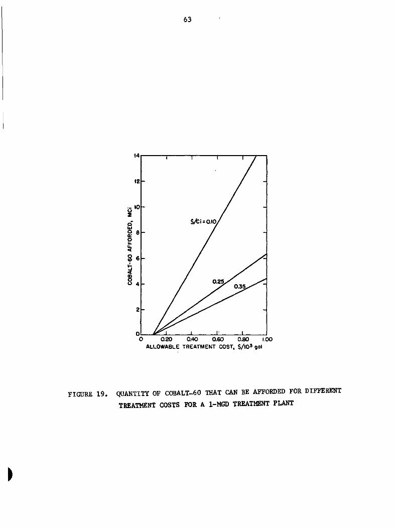
63
0 0.20 0.40 0.60 0.80 1.00 ALLOWABLE TREATMENT COST, $ / lO ' QOl
FIGURE 1 9 . QUANTITY OF COBALT-60 THAT CAN BE AFFORDED FOR DIFFERENT
TREATMENT COSTS FOR A 1-MGD TREATMENT PLANT
>
64
solubility which is directly temperature dependent. However, with ice it
forms hydrates of the general formula Kr«6H20 that have a dissociation
pressure of 14.5 atmosphere at 0 C. Its solubility in organic solvents
such as freons is known; for other solvent systems it is not known.
These properties of krypton-85 suggest that it could be incorpora
into reaction media. When used with a gas mixture that yields a condensed
phase product, batch reactions are possible if the krypton-85 can be
recovered efficiently. Direction treatment of liquids is also possible
by sparging and recycling of the kr3T)ton-85 followed by a stripping opera
tion to assure removal of the gas from the liquid. When used with liquids,
(1) The krypton-85 must not be soluble or at least the solubility should be temperature dependent for ease of recovery
(2) If the krypton-85 is soluble, it must be readily removed and recoverable
(3) Provisions for recovery and reuse would be mandatory
(4) Leakproof gas handling system and storage would be mandatory because of the hazard and the relatively high cost/Ci.
Specific Applications
Reports on the use of krypton-85 for waste disposal or waste
desensitization have not been found. Potential applications developed
herein are related either to the unique characteristics of the use of a
nonreactive radioactive gas or to unusual requirements for specific
waste disposal or waste treatment objectives.
Military Unique Waste Disposal or Waste Treatments. The
demilitarization programs under way in the Department of Defense pose
some unique disposal and treatment problems. Biological- and chemical-
warfare agents in particular are hazardous materials requiring specialized
treatment and disposal techniques. In addition to these, many other
65
materials that are by-products of manufacturing operation or detoxification
treatments are often encountered as fluid waste% either as contaminated or
off-grade materials or as pollutants in wastewater from the processing
operation.
Germ Warfare Agents. Krypton-85 may provide a unique method for
the destruction of pathogenic bacterial agents that are being removed from
the military arsenal. As a gas it could be introduced into containers holding
these agents, effect the "kill", and then be recovered for reuse. The process
could employ the recent findings on the synergistic effect of the addition
of heat as well as radiation on the extent and rate of microbiological
kills. Thermoradiation sterilization as it is called combines the dry heat
and ionizing radiation in a way which results in greater microbial
inactivation than the additive effects would imply.^ ^ Replacement of
a fixed radiation source such as cobalt-60 by krypton-85 could provide even
greater utility and could shorten the processing time considerably due
to the intimate contact between the radioactive source and the organism
than could be possible with cobalt-60. Thermoradiation processing reduces
the propensity for mutant formation present when radiation is used alone.^ ^
Similar synergism was observed for the treatment of sewage sludge but the
utility of krypton in such operations seems doubtful because of the large (92)
volumes of wastes that could be encountered.
Chemical-Warfare Agents. The nitrogen and sulfur mustards and the
nerve gases GB and VX are presently being destroyed as part of the overall
demilitarization program. Concentrated streams are being incinerated,
chemically treated (aqueous oxidation^ or hydrolyzed. Treatment of con
taminated aqueous streams is possible in areas where ionizing radiation
might be applied. In general, the approach would be to treat these aqueous
waste streams to convert the biologically refractory organic materials to
substances more readily attacked by microorganisms.
66
GB and VX. In the process of destroying GB, as currently practiced,
the agent is hydrolyzed by strong caustic soda solution and the resulting
brine is spray dried. In the exothermic hydrolysis step, the fluorine atom
is very rapidly hydrolyzed off,but the resulting isopropyl ester of methyl
phosphonic acid sodiim salt (SIM) is very resistant to hydrolysis and
remains in the brine along with sodium fluoride and excess sodium hydroxide.
There is considerable evidence that small amounts of GB are re-formed in
the spray dryer. Studies have shown that treatment of SIM with hydro
fluoric acid will produce GB.
An alternative being considered is to chemically destroy the SIM
in aqueous solution by oxidation. It is known that the combined effect
of oxygen and ionising radiation is capable of altering organic constituents
through the aqueous oxidation route. Destroying SIM in this manner eliminates
the possibility of GB reformation. Thus, a krypton-85 - O2 mixture could
be recirculated through the brine to provide in situ activation and reagent.
Unfortunately, a calculation estimating the quantity of kr3T)ton-85
necessary to destroy all SIM present in a typical day's waste stream
equaled 10 grams of krypton containing 6 percent krypton-85, see Appendix c. Q
This equals approximately 10 curies of krypton-85, a quantity too large
to be practical.
V2^ being more resistant to hydrolysis reaction with caustic
sod^ could possibly be destroyed by simultaneous treatment with ionizing
radiation from krypton-85 passed through the media.
Persistent Organics in Wastewater. Certain organic compounds such
as phenols and various pesticides are resistant to microbial attack in
aqueous systems. Also, in TNT manufacture, trace amounts of nitrated
toluenes or their hydrolysis products (red water) are not amenable to
conventional wastewater treatment and find their way into surface waters.
In such cases, irradiation of the wastewaters in the presence of air or
oxygen has been known to alter compounds such as phenols and render them
suitable to microbial attack. ^'°''^°>
{
67
It is well known that krypton-85 will form clathrates .with phenol-
or quinol-type compounds under suitable conditions of high krypton pressures.
This attraction of such molecules for krypton even in aqueous systems
might provide the means of irradiation in close proximity to these molecules.
Even if the conditions for clathrate compound formation are not attained,
the very fact that these compounds would tend to form suggests some attraction
of these compounds for krypton-85. With simultaneous treatment with air
or 02, and krypton-85 supplying the radiation, rapid conversion of such J J ui (78,80,84,87,89) ^ x u^ u
compounds is possible. > > > > >' xhe use of high gas pressures
would augment the solubility of both gases and enhance the desired
reactions. '
To estimate the quantity of krypton-85 necessary to destroy 500 ppm
refractory molecules in a waste stream flowing at 1 million gallons per day,
a rough calculation was made. Referring to the Appendix C, it is estimated
that 10 grams of krypton (6 percent krypton-85) or 10 curies of krypton-85
is required for this destruction.
Although an order of magnitude less than the requirements for SIM
destruction, this needed krypton quantity is also too large to be practical.
Conclusions
Krypton-85, because of its low-yield gamma radiation, is a rather
poor source for irradiation suitable for chemical processing. Because of
this low gamma level, the bremsstrahlung effects are very narked and could
serve as an alternative, but lower, energy source of gansna radiation.
The limited quantities of krypton-85 and its relatively high cost
per curie, combined with the problems of confining and handling a gas,
suggest that its application to waste treatment may be restricted. The
use of krypton-85 at the 6, 25, and 45 percent levels in mixtures with
other gases such as oxygen will require extensive review and study.
Many questions remain unanswered. For example: Will the potential for
ozone formation require separation of the two gases prior to storage -
Will the concentration be limited by an equilibrium established between

68
the rate of ozone formation and the rate of its decomposition? The most
viable use for krj^ton-SS would be in the dry sterilization treatment of
germ-warfare materials and related areas. It also shows promise where
controlled or modulated irradiation levels are needed.
69
Environmental Control of Submersibles
Environmental control of submersibles was investigated, addressing
mainly the use of krypton-85 heat source applications. The following
specific applications were addressed:
• Submersible environmental control system (ECS)
• Personnel-transfer capsule (PTC) ECS gas heater (He'02 to 1500 feet of seawater)
• Wet suit diver heating system
• Dry suit or unisuit diver heating system
• Submersible battery heater.
The various identified topics are briefly discussed below.
Submersible Environmental Control System
Experiments conducted with a personnel transfer capsule at 1 (93)
atmosphere indicate about 200 watts per F may be needed to heat
an uninsulated steel chamber such as a submersible hull. For a 50 degree
temperature rise (40 F water temperature to 90 F breathing gas tempera
ture) , as much as 3,000 watts may be required.
If krypton-85 power density is assumed to be 0.56 watts per gram
(fully enriched krypton), about 33 kg-moles of the pure isotope would be
required. This requirement is clearly not a practical consideration.
In the first plac% present enrichment procedures cannot give that purity
of krypton-85 in that quantity. And, even if one considers 45 percent
enriched krypton-85, that means at least 6 kilograms would be required.
Finally, even if one could consider obtaining the gas, one would have
to consider shielding the krypton-85, an item that would add considerable
weight to the submersible.
70
Personnel Transfer Capsule Environmental Control Gas Heater
Test results of Reference 93 indicate that an uninsulated
personnel-transfer capsule may require as much as 27,000 watts to
maintain an internal temperature of 90 F when submerged in water at 40 F.
Such a heat load would require too large an inventory of kr3^ton-85.
However, experiments ^ ^^ and calculations indicate that the heat required
for breathing gas to personnel-transfer capsule or recompression-chamber
occupants is not excessive and may be within krypton-85 capacities. The
gas heater ^ ^ worked well with a heat input of about 320 watts and the
calculated heat requirement for an emergency fly-away recompression
chamber could be as low as about 2400 watts. Reference 95 indicates that
the heating load of a large deep-diving chamber complex could be as much
as 7600 watts, which would be excessive for krypton-85.
Wet Suit or Dry Suit Diver Heating System
Heat sources delivering about 1 kilowatt ^ ^ have been identified
as necessary to keep a wet suit diver warm. Although, this heating
requirement could be met using kr3T)ton-85, the shielding required for the
1 kilowatt of krypton-85 would be large and the concept (krypton-85
heater for a wet suit) does not qualify as a good one. As for a dry suit
diver, it is unlikely that he would require much if any external heat as
he is normally wearing thermal underwear in a dry suit.
Submersible Battery Heaters
Reference 97 indicates the feasibility of using radioisotopes
to heat silver-zinc batteries to increase their efficiencies at low
temperatures. Since silver-zinc batteries are commonly used in sub
mersibles, the possibility of heating submersible batteries was investigated.
Generally, submersible batteries are high-drain applications where heat is
actually generated in the silver-zinc cells from their use and, therefore.
71
external heating should not be required. However, where silver-zjLnc
batteries are used in cold waters, then some heating requirements may
exist. Those regions have not been identified, however.
Conclusions
Krypton-85 heaters for submersibles appear to be either
unattractive from the standpoint of cost and quantity or altogether
impractical because of the high thermal inventory required.
72
REFERENCES
(1) Feibrush, A. M., "Research on Applications of Krypton-85 and Other Radioactive Isotopes", Central Research Laboratories, Report NYO-2906-1 (Septeniber, 1964).
(2) "Research Materials, Separated Isotopes, Radioactive Isotopes, Special Preparations", Oak Ridge National Laboratory, Oak Ridge, Tennessee, 6th Revision (April, 1973).
(3) Blomeke, J. 0., and Perona, J. J., "Management of Noble-Gas Fission-Product Wastes from Reprocessing Spent Fuels", ORNL-IM-2677.
(4) Bendixen, C. L., and Offutt, G. F., "Rare Gas Recovery Facility at the Idaho Chemical Processing Plant", IN-1221 (April, 1969).
(5) Love, L. 0., and Bell, W. A., "Review of ORNL Electromagnetic Separation Program, 1968-1969", ORNL-4640 (April, 1971), pp 16-24.
85 (6) Rathkamp, W. R., "The Enrichment of Radioactive Kr", Isotopes and
Radiation Technology, 6, No. 4 (Sunmer, 1969).
(7) Bonnevier, B., "Diffusion Due to Ion-Ion Collisions in a Multicomponent Plasma", Arkiv for Fysik, 33 (15), 255 (1966).
(8) Bonnevier, B., "Experimental Evidence of Element and Isotope Separation in a Rotating Plasma", Report No. 70-08, Kungliga Tekniska Hogskolan, Stockholm, Sweden (June, 1970). Available on microfiche as NP-18643.
(9) Bonnevier, B., "On Centrifugal Effects and Separation in a Rotating Plasma", Division of Plasma Physics, Royal Institute of Technology, Stockholm 70, Sweden (1970),
(10) Lehnert, B., "A Partially Ionized Plasma Centrifuge", Physica Scripta, 2, 106-107 (1970).
(11) Lehnert, B., "The Partially Ionized Plasma Centrifuge", TRITA-EPP-72-01, Division of Plasma Physics and Fusion Research, Royal Institute of Technology, 10044 Stockholm 70, Sweden (1972).
(12) Lehnert, B., "Rotating Plasmas", Nuclear Fusion, 11, 485-533 (1971).
(13) Sabri, Z. A., "Application of Fusion Plasma Technology", ISU-ERI-Ames-74205, ERI Project 1126, Report Period April 1, 1974-September 30, 1974.
(14) Fey, M. G., and Harvey, F. J., "The Role of Plasma Heating Devices in the Electric Energy Economy", Delivered at meeting of American Chemical Society, September 9-12, 1974. Copies of the paper may be obtained by writing to Dr. F. J. Harvey, Westinghouse Electric Coirporation, Churchill Borough, Pittsburgh, Pennsylvania,
73
(15) Drummond, J. E., Chang, D. B., and Mahaffey, D. W., "Plasma Metal Refining Process - By Withdrawing Ionized Metal from a Neutral Gas", Issued to the Boeing Compamy, P.O. Box 3999, Seattle, Washington (September 15, 1972). (Belgian patent).
(16) Lehnert, B. P., "Device for Causing Particles to Move Along Curved Paths", U. S. Patent No. 3,722,677 (March 27, 1973).
(17) Duane, B. H., and Liemohn, H. B., "Nonlinear Rotary Wave Ion Plasma", (BNW Program Plasma-III), BNWL-1796.
(18) Dubrin, J. W., "Laser Isotope Separation", UCRL-75886 (November, 1974).
34 (19) Lyman, J. L., et al., "Isotopic Enrichment of SF, in S by Multiple
Absorption of CO2 Laser Radiation", LA-UR-75-707 (1975).
(20) Gross, R.W.F., "Laser Isotope Separation", Optical Engineering, _13, No. 6 (November-December, 1974).
(21) Sussman, S. S., et al., "Laser-Fusion Program Semiannual Report", UCRL-50021-73-1 (August 22, 1973).
(22) Private Communication with John C. Denqjsey of ERDA, Development Branch Division of Waste Management and Transportation.
(23) Trevarrow, L. E., et al., "Tritium and Noble Gas Fission Products in the Nuclear Fuel Cycle", Volume I Reactors, ANL-8102 (October, 1974).
(24) Deonigi, D. E., McKee, R. W., and Haffner, D. R., "Isotope Production and Availability from Power Reactors", BNWL-716 (July, 1968).
(25) "World List of Nuclear Power Plants", Nuclear News, 17, No. 10 (August, 1974).
(26) McKee, R. W., Deonigi, D. E., and Haffner, D. R., "Isotope Production Projections for U. S. Nuclear Power Reactors", Battelle's Pacific Northwest Laboratories, Report CONF-680308-8 (1968).
(27) "Obstruction Marking and Lighting", Advisory Circular of the Department of Transportation, Federal Aviation Administration, AC No. 70/7460-lC, December 11, 1973.
(28) Private Communication with Harry Dooley of American Atomics Corporation, Tucson, Arizona (June 4, 1975).
(29) Eggers, Philip E., "Development of Thermocouple Generators for Small-Caliber Munitions Fuze", Phase I Final Report to The U. S. Air Force, Aerospace Research Laboratories, Wright-Patterson AFB, ARL TR-75-0013 (March, 1975).
(30) Pietsch, Anthony, "Closed Brayton Cycle Power System Applications", Proceedings of the Fourth Intersociety Energy Conversion Engineering Conference (AICHE), September 22-26, 1969, pp 642-658.
74
(31) Beremand, D. G., et al., "Experimental Performance Characteristics of Three Identical Brayton Rotating Units", Proceedings of the Fifth Intersociety Energy Conversion Engineering Conference (ANS): Energy, No. 70, p 4-18 and 4-26 (1970).
(32) Pouchat, W. D., and Daniels, A., "Nuclear Artificial Heart Bench Model", Ninth Intersociety Energy Conversion Engineering Conference Proceedings (ASME), August 26-30, 1974, pp 782-790.
(33) Martini, W. R., "Unconventional Stirling Engines for the Artificial Heart Application", Ninth Intersociety Energy Conversion Engineering Conference Proceedings (ASME), August 26-30, 1974, pp 791-798.
(34) Boretz, J. E., et al., "Turbine Organic Rankine Engine System for Artificial Heart Application", Ninth Intersociety Energy Conversion Engineering Conference Proceedings (ASME), August 26-30, 1974, pp 813-823.
(35) Feibush, A. M., "Research on Applications of Krypton-85 and Other Radioactive Isotopes", NYO-2906-1 (September, 1964).
(36) Stone, E. W., George, J.H.B., and Beutner, H. P., "Isotopes in Industry", NYO-3337-16 (September, 1965).
(37) Figueroa, C. G., "Krypton Potential in Aerospace", Proceedings of the Second International Symposium on Nucleonics in Aerospace, Columbus, Ohio (July, 1967).
(38) Polluck, E. M., Fujita, M., and Kuser, H. C , "Isotropic Propellant Level Indicator", Ibid.
(39) "Kryptonate Inspection of Embrittled Structures", Contract N0O-156-68-C-0348, Final Report to Naval Air Systems Command, Washington, D.C. by Industrial Nucleonics Corporation, Columbus, Ohio (February, 1968).
(40) Balek, "Application of Inert Radioactive Gases in the Study of Solids", Materials Science, 4 (1969), pp 919-927.
(41) Tiner, N. A., and Asunnaa, S. K., "Microautoradiography of Kryptonated Aluminum Alloys", Materials Research and Standards, JJO, NO. 4 (April, 1970).
(42) Murgatroyd, John L., "Leak Rate Determination Using Krypton-85", IEEE Transactions on Instrumentation and Measurement, IM-21. No. 1 (February, 1972).
(43) Wisnieff, S. F., and Bardach, H., "Radioactive Krypton Simplifies Temperature Mapping of Turbine Blades", SAE Journal, 74, No. 8 (August, 1966), pp 56-59.
(44) Nickola, P. W., Ludwick, J.oP., and Ransdell, Jr., J. V., "Atmospheric Tracer Technique Employing Kr and Use of this Technique in Defining Puff Dimensions and Transport Speed", Isotopes and Radiation Technology, 9, No, 1 (Fall, 1971).
75
(45) Gerrard, Martha, and Lafferty, Jr., R. H., "Kryptonate-Based Instrument for Detecting Automobile-Exhaust Pollutants", Isotopes and Radiation Technology, 8, No. 4 (Summer, 1971).
(46) Bruton, W. A., and Packer, L. L., "Radioactive Temperature Indicator Research and Development", Contract No. NNO-156-69-C-0595, Final Report to Naval Air Systems Command, by United Aircraft Corporation, East Hartford, Connecticut (July, 1970).
(47) Packer, L., and Woody, B., "Radioactive Temperature Indicator Research and Development", Contract No. NOO-156-71-C-0816, Report to the Naval Air Systems Command by United Aircraft Corporation, East Hartford, Connecticut (March, 1972).
(48) Private communication with L. L. Packer, United Aircraft Corporation, East Hartford, Connecticut.
(49) Gerrard, Martha, "Recent DID Radiometric-Technique Developments", Isotopes and Radiation Technology, Vol 9, No. 1 (Fall, 1971).
(50) Ballou, J. E., and Cannon, W, C , "Preliminary Investigation with Inhaled S^Kr in the Rat and Beagle Dog", BNWL-1850 (PTl) (August, 1974), pp 76-77.
(51) Morken, D. A., "Biological Effects of the Radioactive Noble Gases", UR-3490-383 (1973).
(52) Fontenelle, A., and Bergeron, M., "Radloautographic Studies of Krypton-85 Clearance from Rat Incisor Pulp and Surrounding Tissue", Arch. Oral Biology, 18, No. 9 (September, 1973), pp 1069-1076.
(53) Oldendorf, W. H., "Radioisotopic Methods for Cerebral Blood Flow Determination", American Lecture Series, No. 771, pp 27-53 (1970).
(54) Fiechi, Cesare, "Cerebral Blood Flow in Neurological and Neurosurgical Patients", AmericJan Lecture Series, No. 771 (1970), pp 55-75.
(55) Wagner, H. N,, "Radioactive Gases for Studies of the Brain", Central Nervous System Investigation with Radionuclides, pp 125-135, A. J. Gilson, editor, Springfield, Illinois; C. C. Thomas, Publisher (1971).
(56) Reinmuth, 0. M., "Inhalation and Intravenous Methods for Measurement of Cerebral Blood Flow", Ibid.
(57) Lessen, N. A., et al., "Blood Flow Studied by Freely Diffusible Radioactive Indicators: Diagnostic Application in Peripheral Arterial Disease" (Bispebjerg Hospital, Copenhagen), Strahlentherapie, Stonderbaende 65 (1967), pp 145-152.
(58) Gruenfield, J. P., Bankir, L., and Funck-Brentano, J. L., "Study of Renal Blood Flow in the Nonanesthetized Rabbit Using ^^Kr" (Hospital Necker, Paris), Rev. Eur. Etud. Clinical Biology, 17, No. 4 (April, 1972), pp 399-405 (in French).
76
(59) Whitton, J. T., "Calculations of Whole Body Dose from Absorption of an Inhaled Noble Gas", Health Physics, 23, No. 4 (October, 1972), pp 573-575.
(60) Lyngborg, Kjeld, Lindeneg, Ole, and Mellemgaard, Kresten, "New Quantitative Method for Determination of Mitral Regurgitation by Continuous Infusion of an Inert Gas ( Kr) in Aqueous Solution" (Rigshospitalet, Copenhagen), Verk. Deut. Ges. Kreislaufforsch, 31 (1965), pp 285-288 (in German).
85 (61) Sejrsen, Per, "Diffusion Processes Invalidating the Intraarterial Kr
Beta-Particle Clearance Method for Measurement of Skin Blood Flow in Man", Circulation Research, 21 (September, 1967), pp 281-295.
85 (62) Lenaers, A., et al., "Measurement of Cerebral Blood Flow by Kr",
CONF-660121 (1967).
(63) Lundgren, Ove, "Studies of Blood Flow Distribution and Countercurrent Exchange in the Small Intestine", Acta Physiology Scand., Suppl. 303, University of Gothenburg, Sweden (1967), p 42.
(64) Haeggendal, Egil, Johan, Nils, and Norbaeck, Bergt, "On the Components of "Kr Clearance Curves from the Brain of the Dog", Acta Physiology Scand., Suppl. 258, University of Gateborg, Sweden (1966), pp 5-25.
(65) Lundgren, 0., and Kampp, M., "Washout of Intraarterially Injected "•'Kr from the Intestine of the Cat", Experimentia, 22 (1966), pp 268-270.
(66) Ladefoged, J., "The Significance of Recirculation for the Detejnnination of Intrarenal Blood Flow Distribution from Krypton-85 and Xenon-133", Clin. Lab. Invest., 16 (1964), pp 479-480.
(67) Degner, W., Hegewald, H., and Thormann, T,, "Krypton-85 Irradiator with Special Reference to the Radiation Protection Problem in Dermatology", Radiobiol. Radiother., 3 (1962), pp 621-623 (in German),
(68) Holyman, G. B., et al., "Measurement of Muscle Blood Flow in the Human Forearm with Radioactive Krypton and Xenon", Circulation, 30 (July, 1964), pp 27-34.
(69) Cleempoel, H., et al., "Use of Dissolved Kr-85 in the Study of Pulmonary and Bronchial Shunts", CONF-640808-1 (1964).
(70) Hollenberg, Milton, "Hepatic Blood Flow Measured by the Portal Venous and Hepatic Arterial Routes with Krypton-85", CONF-650112-1 (1965).
(71) Lessen, N, A., and Klec, A., "Cerebral Blood Flow Determined by Saturation and Desaturation with Krypton-85: An Evaluation of the Validity of the Inert Gas Method of Kety and Schmidt", Circulation Research, 16 (1965), pp 26-32.
(72) Alexander, S, C , et al., "Krypton-85 and Nitrous Oxide Uptake of the Human Brain During Anesthesia", Anesthesia, 25 (January-February, 1964), pp 37-42.
77
Wagner, Jr., H. N., "Regional Blood Flow Measurements with Krypton-85 and Xenon-133", TID-7678 (1964), pp 189-212.
Donato, L., et al., "Quantitative Radiocardiography II. Technic and Analysis of Curves", Circulation, 26 (August, 1962), pp 183-188.
Lewis, M. L., et al., "Quantitative Radiocardiography III. Results and Validation of Theory and Method", Circulation, 26 (August, 1962), pp 189-199.
Lassen, N. A., "Assessment of Tissue Radiation Dose in Clinical Use of Radioactive Inert Gases with Examples of Absorbed Doses from H, °^Kr, and 133xe", Minerva Nucl., 8 (July-August, 1964), pp 211-217.
Handbook of Chemistry and Phvsics. Charles D. Hodgeman, editor. The Chemical Rubber Publishing Company, Cleveland, Ohio, 42nd edition (1961).
Ballantlne, "Potential Role of Radiation in Waste-Water Treatment", Isotopes and Radiation Technology, 8, No. 4 (1971), p 415.
Steinberg, Meyer, and Beller, Morris, "High Energy Radiation Synthesis of Ozone for Water Treatment", Ibid., p 420.
Gerrard, Martha, "Sewage and Waste-Water Processing with Isotopic Radiation: Survey of the Literature", Ibid., p 429.
Gerrard, Martha, "Conceptual Design of an Irradiation Test Facility for Waste Water and Sewage Sludge", Ibid., p 435.
Mann, Leland A., "Biological-Gamma Radiation System for Sewage Processing", Ibid., p 439.
Mytelka, A. J., "Radiation Treatment of Industrial Waste Waters on Economic Analysis", Ibid., p 444.
Campbell, Lome A., "Gamma Irradiation as a Pretreatment to Chemical Precipitation in the Purification of Domestic Sewage", Ibid., p 449.
Vajdic, A. H., "Gamma Irradiation of Waters and Waste Waters for Disinfection PuiTJOses", Ibid., p 451.
Andrews, R. H., and Fielding, M. B., "Gamma Irradiation of Raw Sewage for Sedimentation Purposes", Ibid., p 452.
Comption, D.M.J., "Destruction of Organic Substances in Waste Water by Ionizing Radiation", Ibid., p 453.
Case, F. N., Kau, D. L., Smiley, D. E., and Garrison, A. W., "Radiation-Induced Oxidation of Process Effluents at High Pressure", Isotopes and Radiation Technology, 9, No. 1 (1971), p 101.
Encyclopedia of Chemical Technology. Kirk-Othmer, Vol. 10, 2nd edition (1971), p 888.
78
(90) Sivinski H. D., and Reynolds, M. C , "Synergistic Characteristics of Thermoradlatlon Sterilization" Life Sciences and Space Research X. Akademic-Verlag, Berlin (1972), p 33.
(91) Dillon, R. T., and Conley, M. B., "Rates of Mutant Production in Bacillus Subtilis by Dry Heat and Gamma Irradiation: A Preliminary Report", Sand 75-0037, Sandla Laboratories, Albuquerque, New Mexico 87115 (April, 1975).
(92) Sivinski, H. D., "Treatment of Sewage with Combination of Heat and Ionizing Radiation (Thermoradlatlon)", lAEA-SM-194/303, IAEA Symposium on the Use of High Level Radiation in Waste Treatment - Status and Prospects, Munich, Germany (March 17-21, 1975).
(93) "Experimental Determination of Heat Requirements for the Mark I PTC", Battelle,Colimibus Laboratories Task Report to U.S. Navy, Supervisor of Diving, Septeniber 8, 1969.
(94) "Development of an Experimental Breathing Gas Heater", Battelle, Columbus Laboratories, Task Report to the Navy, Supervisor of Diving, September 24, 1969.
(95) "Preliminary ECS Performance Specification" prepared by Battelle, Columbus Laboratories, for proposed Canadian Navy Diving Chamber Complex.
(96) Proceedings from Committee Meeting on Diver Heating. LCdr Majendie, Chairman, held at the U.S. Navy Experimental Diving Unit, February, 1969.
(97) Levy, I. M., and Bustard, T. S., "A Radioisotope Heater for a Silver-Zinc Battery", Nucleonics in Aerospace, New York, Plenum Press (1968), pp 200-207.
(98) Matheson Gas Data Book, Matheson Company, 4th edition (1966) p 313.
(99) Handbook of Chemistry and Physics, Charles D. Hodgeman, editor. The Chemical Rubber Publishing Company, Cleveland, Ohio, 42nd edition (1961).
(100) Arnold, E. D., Handbook of Shielding Requirements and Radiation Characteristics of Isotonic Power Sources for Terrestrial. Marine, and Space Applications. ORNL 3576 (April, 1964).
(101) National Bureau of Standards Certificate Standard Reference Material 4935-C, Radioactivity Standard, Kr3rpton-85, National Bureau of Standards (March 29, 1974).
APPENDIX A
SELECTED PHYSICAL PROPERTIES OF KRYPTON-85
>
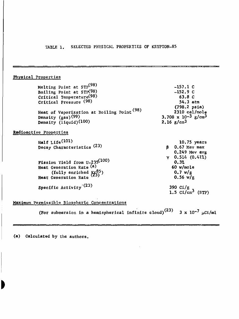
TABLE 1. SELECTED PHYSICAL PROPERTIES OF KRYPTON-85
Physical Properties
Melting Point at STP^ -157.1 C Boiling Point at STpC98) -152.9 C Critical Temperature(98) 63.8 C Critical Pressure (98) 54.3 atm
,gs^ (798.2 psia) Heat of Vaporization at Boiling Point'' -' 2310 cal/mole Density (gas)(99) 3.708 x 10⁻³ g/cm^ Density (liquid)(100) 2.16 g/cm3
Radioactive Properties
Half Life(101) 10.75 years Decay Characteristics ^ ^ P 0.67 Mev max
0.249 Mev avg
riOO^ Y 0.514 (0.41%) Fission Yield from U-235<>1"") 0 3 ^ Heat Generation Rate ( ) 60 w/mole
(fully enriched Yi^P) 0.7 w/g Heat Generation Rate ' ^ 0.56 w/g
Specific Activity'(^^) 390 Ci/g
1.5 Ci/cm^ (STP)
Maximum Permissible Biospheric Concentrations
(For submersion in a hemispherical infinite cloud)^ ^ 3 x 10"' tiCi/ml
(a) Calculated by the authors.
APPENDIX B
THE NUCLEAR POWER INDUSTRY
^
APPENDIX B
THE NUCLEAR POWER INDUSTRY
U.S. Commercial Power Reactor Characteristics 1960 - 1990
Appendix B Includes several figures and tables which provide
more insight into the production of fission products from U.S. commercial
power reactors. Figures B-1 and B-2 show the projected growth of
commercial nuclear power plants over the next 15 years while
Tables B-1 through B-6 give projected kr3rpton-85 and stable krjrpton
isotope yields.
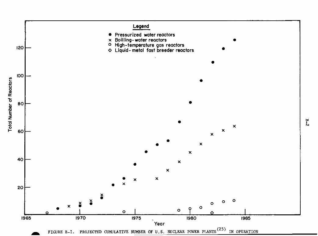
~
—
. ^ f 0 1
X •
Legend
• Pressurized water reactors X Boil ling-water reactors o High-temperature gas reactors O Liquid-metal fast breeder reactors
•
•
•
•
• X
• X
X
• X X • X
X •
o 1 o ^ °
•
X
o
•
X
o
•
X
o
1 1965 1970 1975 , 1980 1985
Year
^^ FIGURE B-1. PROJECTED CUMULATIVE NUMBER OF U.S. NUaEAR POWER PTJ NTS ^ IN OPERATION
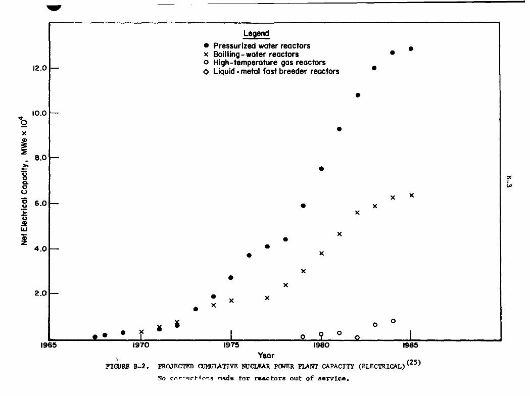
Legend
• Pressurized water reactors ^ X Boilling-water reactors • o High-temperature gas reactors O Liquid-metal fast breeder reactors *
X X
X X
f > • f s
X
X
• X X
» o °
1965 1970 1975 1980 1985 Year
FIGURE B-2. PROJECTED CUMULATIVE NUCLEAR POWER PLANT CAPACITY (ELECTRICAL)^^^^
No cnr-ecHons made for reactors out of service.
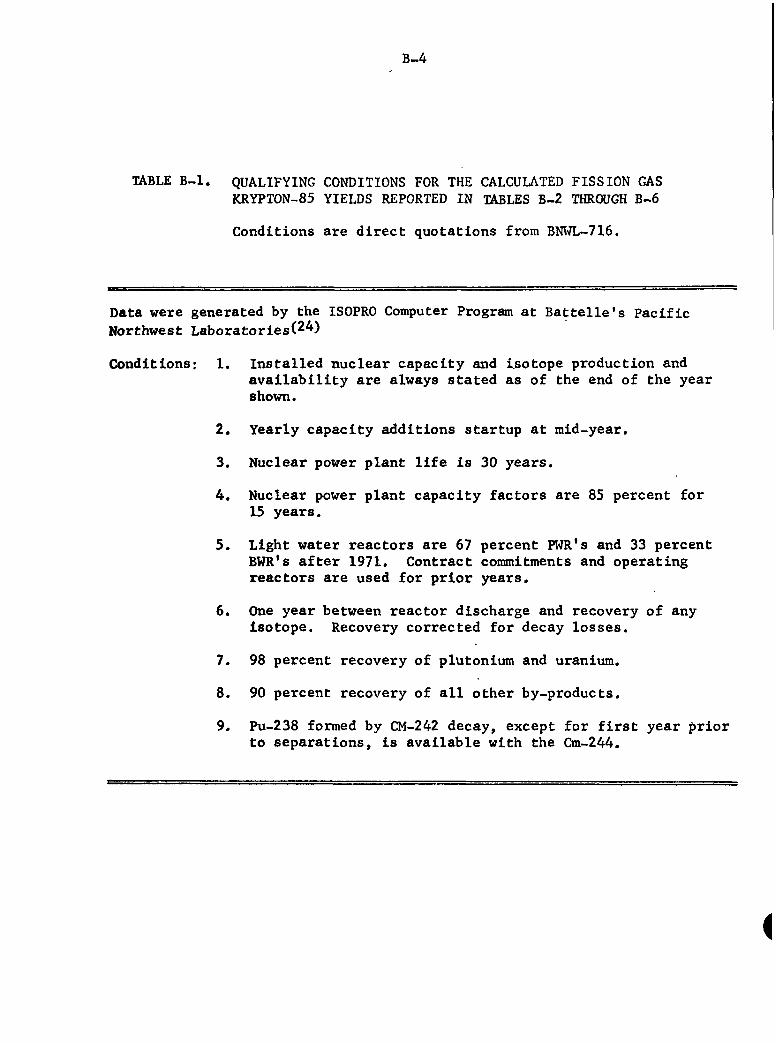
B-4
TABLE B-1. QUALIFYING CONDITIONS FOR THE CALCULATED FISSION GAS KRYPTON-85 YIELDS REPORTED IN TABLES B-2 THROUGH B-6
Conditions are direct quotations from BNI"7L-716.
Data were generated by the ISOPRO Computer Program at Battelle's Pacific Northwest Laboratories(2^)
Conditions: 1. Installed nuclear capacity and ijsotope production and availability are always stated as of the end of the year shown.
2. Yearly capacity additions startup at mid-year.
3. Nuclear power plant life is 30 years.
4. Nuclear power plant capacity factors are 85 percent for 15 years.
5. Light water reactors are 67 percent Roll's and 33 percent BWR's after 1971. Contract commitments and operating reactors are used for prior years.
6. One year between reactor discharge and recovery of any Isotope. Recovery corrected for decay losses.
7. 98 percent recovery of plutonium and uranium.
8. 90 percent recovery of all other by-products.
9. Pu-238 formed by CM-242 decay, except for first year prior to separations, is available with the Cm-244.
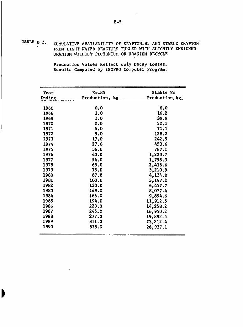
B-5
TABLE B - 2 . CUMULATIVE AVAILABILITY OF KRYPTON-85 AND STABLE KRYPTON FROM LIGHT WATER REACTORS FUELED WITH SLIGHTLY ENRICHED URANIUM WITHOUT PLUTONIUM OR URANIUM RECYCLE
Production Values Reflect only Decay Losses. Results Computed by ISOPRO Computer Program.
— Year End ing
1960 1966 1969 1970 1971 1972 1973 1974 1975 1976 1977 1978 1979 1980 1981 1982 1983 1984 1985 1986 1987 1988 1989 1990
Kr-85 Production, kg
0.0 1.0 1.0 2.0 5,0 9.0 17,0 27,0 36,0 43,0 54,0 65,0 75,0 87,0 103.0 133.0 149.0 166.0 194.0 223.0 245.0 277.0 311.0 338.0
Stable Kr Production, kg
0.0 16,2 39.9 52.1 71.1 128.2 242.5 453.6 787.1
1,223.7 1,758.3 2,416.6 3,210.9 4,134.0 5,197.2 6,457.7 8,077.4 9,894.6 11,912.5 14,258.2 16,950.2 19,892.5 23,212.4 26,937.1
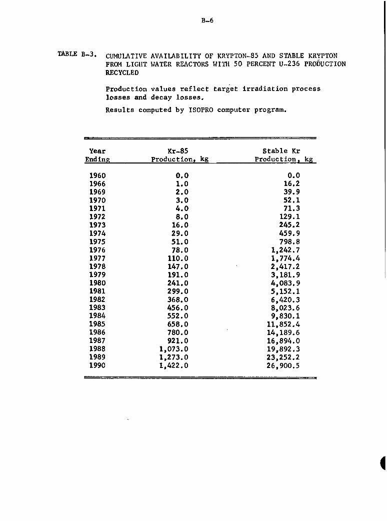
B-6
TABLE B-3. CUMULATIVE AVAILABILITY OF KRYPTON-85 AND STABLE KRYPTON FROM LIGHT WATER REACTORS WITH 50 PERCENT U-236 PRODUCTION RECYCLED
Production values reflect target irradiation process losses and decay losses.
Results computed by ISOPRO computer program.
Year Ending
1960 1966 1969 1970 1971 1972 1973 1974 1975 1976 1977 1978 1979 1980 1981 1982 1983 1984 1985 1986 1987 1988 1989 1990
Kr-85 Production, kg
0.0 1,0 2.0 3,0 4,0 8.0 16,0 29.0 51.0 78.0 110.0 147.0 191.0 241.0 299.0 368.0 456.0 552.0 658.0 780.0 921.0
1,073.0 1,273.0 1,422.0
Stable Kr Production, kg
0.0 16.2 39.9 52.1 71.3 129.1 245,2 459.9 798.8
1,242.7 1,774.4 2,417.2 3,181.9 4,083.9 5,152.1 6,420.3 8,023.6 9,830.1 11,852.4 14,189.6 16,894.0 19,892.3 23,252.2 26,900.5
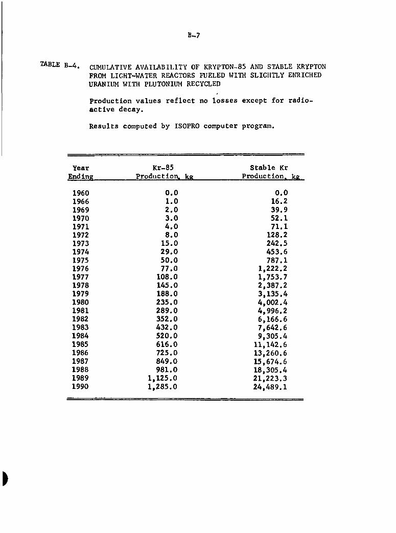
B-7
TABLE B-4, CUMULATIVE AVAILABILITY OF KRYPTON-85 AND STABLE KRYPTON FROM LIGHT-WATER REACTORS FUELED WITH SLIGHTLY ENRICHED URANIUM WITH PLUTONIUM RECYCLED
Production values reflect no losses except for radioactive decay.
Results computed by ISOPRO computer program.
Year Ending
1960 1966 1969 1970 1971 1972 1973 1974 1975 1976 1977 1978 1979 1980 1981 1982 1983 1984 1985 1986 1987 1988 1989 1990
Kr-85 Production, kg
0.0 1.0 2.0 3.0 4,0 8,0 15.0 29.0 50.0 77.0 108.0 145.0 188.0 235.0 289.0 352.0 432.0 520.0 616.0 725.0 849.0 981.0
1,125.0 1,285.0
Stable Kr Production, kg
0.0 16.2 39.9 52.1 71.1 128.2 242.5 453.6 787.1
1,222.2 1,753.7 2,387.2 3,135.4 4,002.4 4,996.2 6,166.6 7,642.6 9,305.4 11,142.6 13,260.6 15,674.6 18,305.4 21,223.3 24,489.1
B-8
TABLE B-5. CUMULATIVE AVAILABILITY OF KRYPTON-85 AND STABLE KRYPTON FROM LIGHT^ATER REACTORS FUELED WIlTi SLIGHTLY ENRICHED URANIUM WITH PLUTONIUM AND 50 PERCENT OF U-236 RECYCLED
Production values reflect no losses except for radioactive decay.
Results computed by ISOPRO computer program.
Year Ending
1960 1966 1969 1970 1971 1972 1973 1974 1975 1976 1977 1978 1979 1980 1981 1982 1983 1984 1985 1986 1987 1988 1989 1990
Kr-85 Production, kg
0,0 2,0 4,0 5,0 9.0 18,0 35,0 60,0 93,0 130.0 172.0 221.0 278.0 340.0 416.0 510.0 614.0 727.0 857.0
1,006.0 1.164.0 1,338.0 1,522.0 1,721.0
Stable Kr Production, kg
0.0 25.8 27.9 79.2 143.4 272.5 511.0 887.5
1,379.6 1,966.5 2,658.1 3,463.2 4,403.1 5,509.1 6,827.4 8,469.2 10,296.9 12,343.6 14,693.7 17,401.8 20,360.4 23,651.3 27,205.2 31,116.3
B-9
TABLE B-6. CUMULATIVE AVAILABILITY OF KRYPTON-85 AND STABLE KRYPTON FROM LIGHT-WATER REACTORS WITH 50 PERCENT U-236 RECYCLE AND MAXIMUM FAST BREEDER REACTOR ADDITIONS BEGINNING IN 1980
Values reflect target irradiation process losses as well as radioactive decay losses.
Results computed by ISOPRO computer program.
Year Kr-85 Stable Kr Ending Production, kg Production, kg
1960 1966 1969 1970 1971 1972 1973 1974 1975 1976 1977 1978 1979 1980 1981 1982 1983 1984 1985 1986 1987 1988 1989 1990
0.0 1.0 2.0 3.0 4.0 8.0 16.0 29.0 51.0 78.0 110.0 147.0 191.0 241.0 299.0 367.0 454.0 548.0 651.0 767.0 898.0
1,038.0 1,190.0 1,344.0
0.0 16.2 39.9 52.1 71.3 129.1 245.2 459.9 798.8
1,242.7 1,774.4 2,417.2 3,181.9 4,083.9 5,152.1 6,415.0 8,011.0 9,784.4 11,757.0 14,021.9 16,605.5 19,436.6 22,582.2 25,909.7
^
APPENDIX C
QUANTITATIVE ESTIMATION OF KRYPTON~85 QUANTITIES REQUIRED TO DESTROY REFRACTORY MOLECULES
•
APPENDIX C
QUANTITATIVE ESTIMATION OF KRYPTON-85 QUANTITIES REQUIRED TO DESTROY REFRACTORY MOLECULES
Three cases are evaluated here; (1) the quantity of kr3rpton-85
needed to destroy SIM as produced at Rocky Mountain Arsenal, (2) the quantity
to destroy refractory molecules in a tjT>ical waste stream, and (3) a rule
of thumb relating the quantity of krjT)ton-85 needed to destroy a given
quantity of refractory substance in 1-day irradiation. In all cases the
krypton gas is assumed to be 6 percent enriched with krypton-85 and
intimately mixed with the substance being treated.
Case 1
Assuming a molecular weight of 138 for SIM and a waste-stream
rate of 26,000 1/day with a SIM concentration of 420 g/1,* the necessary
destruction rate of the SIM molecule is 79,000 g-moles/day or 4.76 x 10^8
molecules/day.
Assuming a G value of 10 (i.e., 10 SIM molecules destroyed for
every 100 ev of energy absorbed), the destroying radiation must deposit 29
into the SIM stream 4.76 x 10 ev/day.
Krypton at 6 percent krypton-85 enrichment produces 2.13 x 10 29 . 11
Mev/sec-g. Therefore, 4.76 x 10 f 2.13 x 10 , with proper conversion
of units, yields 2.58 x 10 g krypton containing krypton-85 enriched at
6 percent. This quantity, 28.6 tons of krypton, is in excess of that
practical for SIM destruction at RMA.
Case 2
Assume a waste stream containing 500 ppm (500 mg/1) and flowing
at a rate of 1 million gallons per day. Assuming the refractory molecule
*Flnal Report to Edgewood Arsenal on "Treatment of Brine Resulting from Hydrolysis of GB and Alternatives", May 13, 1975.
C-2
to have a molecular weight of 150 yields the required destruction rate
of 1.26 X 10 g-mole/day or 7.6 x 10 molecules/day.
Assuming G = 10, radiation energy absorption must equal
mergy 6
28 11 7.6 X 10 ev/day. Using the value of 2.13 x 10 Mev/sec-g for energy production from krypton (6 percent enriched with krjrpton-SS), 4.12 x 10
g of kr}T)ton is required for destruction.
Case 3
Assuming the existence of a general waste stream containing
refractory molecules of molecular weight 150, and a radiation source of
krypton containing krypton-85 at 6 percent enrichment, destruction
requirements dictate that approximately 2 g of krypton is required to
destroy each gram of refractory molecule for 1 day's irradiation.