Embed Size (px)
Citation preview

California State University, San Bernardino California State University, San Bernardino
CSUSB ScholarWorks CSUSB ScholarWorks
Theses Digitization Project John M. Pfau Library
1999
An effective AutoCAD curriculum for the high school student An effective AutoCAD curriculum for the high school student
William Christopher Brown
Follow this and additional works at: https://scholarworks.lib.csusb.edu/etd-project
Part of the Vocational Education Commons
Recommended Citation Recommended Citation Brown, William Christopher, "An effective AutoCAD curriculum for the high school student" (1999). Theses Digitization Project. 1791. https://scholarworks.lib.csusb.edu/etd-project/1791
This Project is brought to you for free and open access by the John M. Pfau Library at CSUSB ScholarWorks. It has been accepted for inclusion in Theses Digitization Project by an authorized administrator of CSUSB ScholarWorks. For more information, please contact [email protected].

AN EFFECTIVE AUTOCAD CURRICULUM
FOR THE HIGH SCHOOL STUDENT
A Project
Presented to the
Faculty of
California State University,
San Bernardino
In Partial Fulfillment
of the Requirements for the Degree
Master of Arts
in
Education: Vocational
By
William C. Brown
June 1999

AN EFFECTIVE AUTOCAD CURRICULUM
FOR THE HIGH SCHOOL STUDENT
A Project
Presented to the
Faculty of
California State University,
San Bernardino
by
William Christopher Brown
June 1999
Approved by:
^^^ji^^^iicarcella, Ph.D., First Reader Date
Jo|afi Emerson, M. A., Second Reader
Abstract
The instruction of computer assisted drafting (CAD) in the high school classroom
presents unique problems and challenges that typical colleges, technical schools, and
industry do not have to address. Issues such as cross curriculum instruction, beginning
and advanced students in the same class, several courses in the same room, CAD and
manual drafting taught concurrently, shorter class periods, and limited resources. In
addition, curriculum must meet the California State Frameworks for Industrial Education
in the area of Visual Communication: Drafting.
The objective of the curriculum will be to expose students to CAD. Students will
be proficient enough with the CAD softwme to be able to visually communicate their
ideas, using industry standards. The most popular CAD software for the microcomputer
presently is AutoCAD, rationalizing my use of it for the project. The curriculum will be
set up so students will need a minimum of teacher lecture/demonstration of commands.
The sequence of commands learned will be carefully and thoughtfully planned. Students
will be expected to learn at their own pace, in an environment of peers who are both more
and less proficient using CAD than themselves. The teacher's role will be predominantly
that of facilitator, however teacher demonstrations in critical m°eas will be essential to
speeding up the learning process for most students.
Functions of CAD that integrate with other high school subject areas will be
emphasized. For example: the Cartesian coordinate system on the CAD screen and
graphing using the x-y axis in Algebra.
Ill

The project will focus on the high school student. Traditional textbooks and
The texts do not give enough age-appropriate drawing problems. The texts also fhtstrate
need to be exposed to yet.
Assessment of student work will be performance-based. Student work can be
evaluated on diskettes or plotted drawings or a combination of both.
IV

Table of Contents
ABSTRACT iii
CHAPTER ONE; BACKGROUND
Introduction 1
Context of the Problem 1
Purpose of the Project 2
Significance of the Project 2
Delimitations 4
Limitations 4
Definition of Terms 4
Organization of the Project 5
CHAPTER TWO: REVIEW OF THE LITERATURE
Introduction 5
History of CAD 5
Industry Transformation from Manual Drafting to CAD 7
Hardware and Software . . .8
The History of AutoCAD, Operating Systems, and the Microcomputer 10
Introduction to ANSI Standards for Drafting 12
CHAPTER THREE: METHODOLOGY
Introduction . 14
Reference Materials 14
AN SI Standards 15
CHAPTER FOUR: FINANCIAL CONSIDERATIONS
Introduction 17
Hardware 17
Low Budget 18
Medium Budget ; 18
High Budget 19
CHAPTER FIVE: SUMMARY
Introduction 21
Project Development 22
APPENDIX A: QUESTIONAIRE RESULTS .. 23
APPENDIX B: DESIGN DRAFTING USING AUTOCAD SOFTWARE AS A TOOL
FOR HIGH SCHOOL STUDENTS 28
REFERENCES 99
VI
Chapter One: Background
Introduction
The content of Chapter One is an overview of the computer assisted drafting (CAD)
curriculum project. The context of the problem is introduced, followed by the purpose
and significance of the project. Next, the limitations and the de-limitations that apply to
the project are reviewed. A definition of terms is presented at the end of the project.
Context of the Problem
Industry's change from manual drafting to CAD is significant. CAD has become
the cornerstone of visual communication in industry, and has become the rule rather than
the exception, when choosing a media to visually communicate.
Teaching high school students in today's advanced and diverse technologies is
becoming increasingly complicated. Typical high school "drafting" classes offer several
areas of emphasis such as engineering drafting, architecture, technical illustration, and
model making.
The modem high school drafting and architecture course's main objectives are to
train students to utilize manual and computer-aided drafting techniques to industry
standards and to visually communicate within industry. Current textbooks used for
training adults, whether manual or CAD, many times do not meet the needs of the typical
high school drafting student. Most CAD textbooks do not incorporate age-appropriate
engineering drawings or problems with basic CAD exercises. The "industry texts" are
comprehensive, complicated reference manuals, written at the college level, with
inappropriate drawing problems and exercises for high school-level students. The CAD
. I . . ■
texts are written with the goal of software instruction, not visual communication using
CAD as a tool to communicate. Typical CAD texts also do not take into account the
cross-curricular instructional objectives of high school education, or meet the needs of
students with lower reading comprehension skills than the typical draftsman.
High school drafting instructors who teach CAD have been left to design an
appropriate curriculuni on their own to meet the heeds of their students.
Purpose of the Project
The purpose of the project is to develop a workbook that incorporates age-
appropriate drawing problems, design problems, and the critical commands of CAD. A
teacher with 35 students cannot provide extensive one-on-one instruction, so the
workbook will be designed to eliminate common problems and questions directed toward
the teacher. The workbook will be designed to meet the needs of combination classes,
with exercises from several different disciplines. Reducing the number of texts required
to effectively communicate lessons will reduce the amount of money dedicated to books
and allow distribution to other important areas (like new software and hardware). The
workbook will be designed so changes (all too frequent) in revisions of AutoCAD will
not significantly effect the workbook. The workbook will be formatted to allow students
to work at their own pace.
Significance of the Project
High school drafting teachers generally require several resources for teaching
Design Drafting or Architectural Drafting and Design using AutoCAD. The workbook
will incorporate drawings from various textbooks that challenge high school students at
various levels. Drawings that promote confusion and misrepresentation of ANSI
standards will not be in the manual.
This resource will help students meet performance objectives as outlined by the
California State Frameworks for Visual Communication-Drafting. The workbook will
help decrease the amount of time that the teacher spends with each drafting student
explaining common CAD commands and errors. Decreased teacher time spent on
software instruction should increase the time allotted for the drafting teacher to teach
visual communication concepts such as; Orthographic projection, dimensioning
techniques and standards, floor plan design criteria, product design, etc. Students will
progress through the software system while learning current drafting and architectural
techniques.
Evaluation of completed student work will be a fimction of the sequence of
problems selected. Beginner-level drawings will be teamed with beginner-level CAD
commands. For example, a one-view sheet metal pattern would incorporate basic CAD
commands like "line", "offset", "circle", and "chamfer". This strategy would allow
students to produce dravrings quickly, while learning CAD commands without being
overwhelmed by the complexity of the software system. Finished drawing problems that
incorporated critical CAD commands, and cross-curricular instruction will be available
for the teacher to critique and "redline". It is important to remember that CAD is a tool
for visual communication. The tools will change (quickly) over time, but visual
communication techniques will remain predominantly the same over time.
Delimitations
The target audience for this project is high school students enrolled in a
combination CAD/Drafting/Architecture class. The curriculum is not written for the
college level student, but could be used in introductory level classes at the college or
technical school level.
Limitations
The project will be designed to accompany standard texts and CAD manuals, not
to replace them. AutoCAD revision 12 is the software the project will be designed
around, so schools using different revisions, or changing revisions, will have to make
adjustments to the "commands" portion of the project.
Definition of Terms
The following terms are defined as they apply to this project:
ANSI: The abbreviation for the American National Standards Institute (Spencer, 1995).
AutoCAD: Computer-Aided Drafting (CAD) software developed by Autodesk
(Shumaker, 1994).
Command: A code that directs the computer to perform a particular operation or
sequence of operations (Shumaker, 1994).
Communication: The exchange of ideas, messages, or information (California department
of education, 1996).Computer assisted drafting (CADV The use of computers and
peripheral devices to aid in the documentation for design projects (Wallach, 1989).
Cross-curricular instruction: The integration of one subject matter into one or more other
subject matters (California department of education, 1996).
Framework A dynamic document providing direction and coherence for collaborative
program and curriculum developnient (California departmeht of education, 1996).
Hardware: The tools available to users of CAD for input, processing, and output
(Wallach, 1989).
Revision: A change from the previous modeKShumaker, 1994).
Software: A set of programs, procedures, rules, and possibly associated documentation
concerned with the operation of a CAD system (Wallach, 1989).
Organization of the Proj ect
This project is divided into five chapters. Chapter One provides an introduction to
the context of the problem, purpose of the project, significance of the project, limitations
and delimitations, and definition of terms. Chapter Two consists of a review of the
literature. Chapter Three outlines the population to be served and the project design.
Chapter fotir supplies the budget information. Chapter Five presents the conclusions and
recommendations generated froni the project. The project and references follow Chapter
■ ■■Five.
Teaching high school students in today's advanced and diverse technologies is
becoming increasingly complicated The purpose of the proj ect is to develop a workbook
that incorporates age-appropriate drawing problems, design problems, and the critical
commands of cad specifically for high school students By using the workbook and the
drafting teacher as a resource, students will progress through the software system
(AutoCAD) while learning current drafting and architectural techniques.
Chapter Two: Review of the Literature
Introduction
Chapter Two consists of a discussion of the relevant literature. The history
of computer-aided drafting (CAD), industry's transformation from manual drafting to
CAD, hardware and software, and an introduction to the American National Standards
Institute's (ANSI) dimensioning standards.
History of CAD
Early drafters measured distances with crude scales and made freehand sketches.
Later drafters used simple wooden straightedges as an aid to drawing. For centuries
drafters used T-squares, triangles, and compasses to draw more accurate lines, arcs, and
circles. Later, the development of the drafting machine and parallel slide systems
enabled drafters to draw much faster and with greater accuracy. Today, computer
systems give drafters the ability to literally draw at the speed of light.
Computer systems designed to perform drafting functions are known as computer-
aided drafting systems (CAD). Computer systems with the capacity to graphically solve
more complex design problems are called computer-aided drafting and design systems
(CADD). Drafters interact with CAD or CADD systems to rapidly produced drawings
that are extremely accurate, consistent, and easily changeable.
Early CAD systems of the '60s, like all early computer systems, were extremely
large, expensive, complicated, and difficult to use. Some systems filled entire rooms and
cost millions of dollars. Today's personal computer systems are smaller, faster, less
expensive, easier to use, and can perform more complex tasks. These improvements and
changes were made possible by the development and continued refinement of the
integrated circuit chip (IC). This development led to enormous expansion in the use of
CAD systems in all phases of drafting, design, engineering, manufacturing, and
construction. The developmental process continues with breakthroughs in system size,
speed, accuracy, and ease-of-use (Wallach, 1989).
Industry Transformation from Manual Drafting to CAD
The rapid growth of computer-aided drafting on the microcomputer (micro-CAD)
is relatively new, but micro-CAD itself is not. There have been micro-CAD systems in
use since the late 1970's. However, these earlier systems were seriously lacking in real
design and drafting capabilities. Early microcomputers had neither the processing power
nor the graphic capabilities needed in CAD. Consequently, micro-CAD got off to a bad
start. Early micro-CAD systems were slow, limited to only the most basic two-
dimensional drafting tasks, and able to produce documentation of only marginal quality.
Such systems were thought of as being "toys", and for the most part rejected by the
private sector. For the most part, the problems associated with early micro-CAD systems
grew out of the problems with early microcomputers. Before micro-CAD could become
a real alternative for companies that wished to convert to CAD but could not afford
traditional systems, two things had happened.
1. Development of the microcomputer had to reach the point where more memory
and processing power were available.
2. The element of the microcomputer had to reach the point where better graphic
capabilities were available.

By the early 1980s both of the developments had taken place. The powerful 16-bit
microcomputers were available. Microcomputers of 512K bytes of RAM became
commonplace. Dual disk drive configurations or a combination hard disk with one
floppy disk drive also became the norm. High-resolution color monitors became readily
available at affordable prices. These developments paved the way for the acceptance of
micro-CAD (Chalk, 1994, p.397).
Hardware and Software
The physical pieces of equipment used in computer-aided drafting and design are
referred to as hardware. The microcomputer is the main component and is accompanied
by several other devices called peripherals. The specific components included in a CAD
workstation are the computer, monitor, keyboard, pointing device, storage device, printer,
and plotter.
The "computer" contains the central processing unit (CPU), memory, disk
drive(s), and hard disk drives. The CPU is the heart of the computer and handles all of the
system's calculations. They are generally graded by processing speed in megahertz
(MHz). Today's fastest microcomputer CPU "run" at 333 MHz. The CPU also contains
"cards" that control the components that will be attached to the computer. Video display
(monitor), mouse ports, keyboard ports, extra memory, sound, and CDROM can have
cards placed in the CPU (Shumaker, 1996). It is advantageous to use the fastest CPU and
the most memory (RAM) that is affordable, to run AutoCAD optimally. Sites may
consider upgrading the video RAM to give better video results.
The "monitor" is the output or display device that resembles a small TV. The
monitor is "graded" by size and resolution. Monitors are generally available in sizes from
14" to 21", but can be larger (Shumaker, 1996). Larger monitors reduce eye-strain for
AutoCAD users. Bigger is better! Nearly all monitors are now color-compatible. Clarity
of the monitor picture is controlled by "resolution". Resolution refers to the number of
dots on the screen; The more dots, the closer they are to each other, the clearer the
picture. A monitor with a resolution of640 X 480 would show objects on the screen as
more "jagged" than a monitor with a resolution of 1024 X 768. Graphics applications like
AutoCAD generally take advantage of monitors with high resolutions to project their
images clearly.
The "keyboard" is generally the most used input device at the workstation.
Commands can be typed in from the keyboard to initiate the CPU to process information.
Function keys on the keyboard (Fl, F2...) can be programmed to perform specific, time
saving commands (Shumaker, 1996). Ergonomic keyboards are available and may be a
welcome system addition for users who input AutoCAD commands predominantly with
the keyboard.
The "pointing device" allows the user to select point locations and commands
from a screen or a digitizer tablet menu, by moving the cursor or crosshairs on the screen.
Common pointing devices are the multi-button puck, pen-shaped stylus, mouse, and
trackball (Shumaker, 1996). Mice are quality, inexpensive pointing device solutions for
the classroom. It is probably best to spend classroom system money other places than
expensive digitizers.

The "storage device" in the computer will be a hard drive, a floppy drive(s), and
perhaps a "zip-drive". Programs are stored on the hard drive (e.g. AutoCAD, Windows
95, Microsoft Word). Drawings can be stored on any of the previously mentioned drives.
AutoCAD drawings are getting larger and larger as its options increase. Most companies
and schools save their drawings on the hard drive and "back-up" the data with floppy
disks. Portable or internal zip drives provide an affordable option to the hard drive and
floppy drive for storing drawing files. Other technologies for file storage and
management such as optical drives and network hubs are available for sites with loftier
needs and budgets.
The "printer" and "plotter" are output devices that produce "hard copies" of the
CAD drawing. A good choice for the classroom is an inkjet plotter. Inkjet plotters
provide affordable, high quality hard copies of CAD drawings. They are faster and more
reliable than the old pen plotters (the pen plotter pens would clog frequently). The plotter
can be networked to several computers or setup with a single computer as a plotter
station.
The History of AutoCAD, Operating Systems, and the Microcomputer
AutoCAD was chosen as the CAD software for the project because it is the
predominantly utilized software in industry (that use microcomputers for CAD). The
increased use of CAD, specifically AutoCAD, has followed a parallel path with the
development and increased performance of Intel's microchips and the Microsoft's
operating systems. A basic chronology of AutoCAD's development and key functions
10
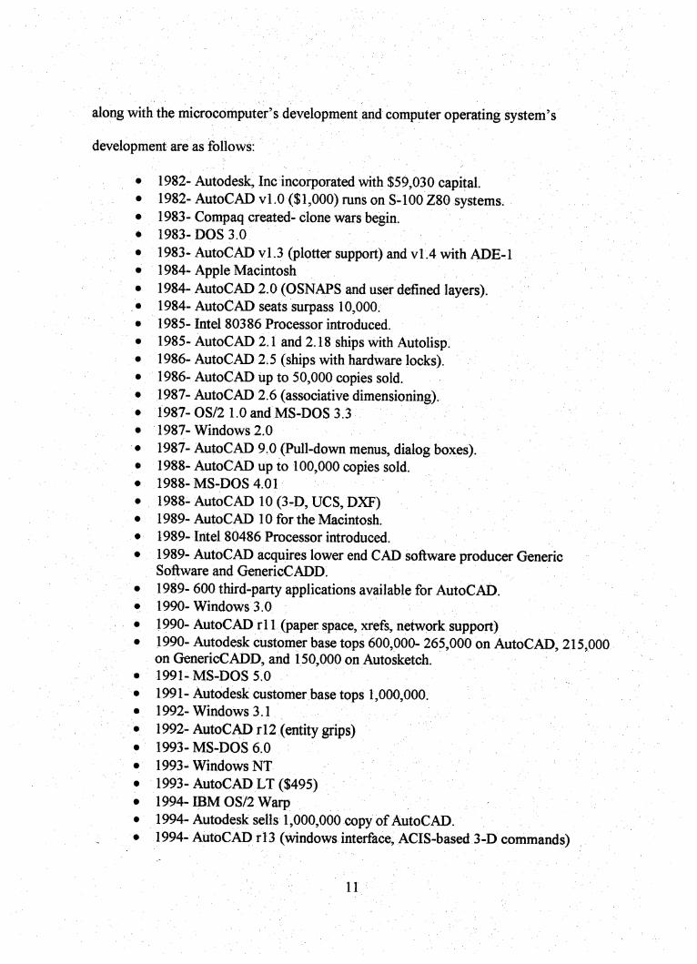
along with the microcomputer's development and computer operating system's
development are as follows;
1982-Autodesk, Inc incorporated with $59,030 capital.1982- AutoCAD vl.O ($1,000) runs on S-100 Z80 systems.1983-Compaq created-clone wars begin.1983-DOS 3.0
1983-AutoCAD yl.3 (plotter support) and vl.4 with ADE-11984-Apple Macintosh1984- AutoCAD 2.0 (OSNAPS and user defined layers).1984-AutoCAD seats surpass 10,000.1985-Intel 80386 Processor introduced.
1985-AutoCAD 2.1 and 2.18 ships with Autolisp.1986-AutoCAD 2.5 (ships with hardware locks).1986-AutoCAD up to 50,000 copies sold.1987-AutoCAD 2.6 (associative dimensioning).1987- OS/2 1.0 and MS-DOS 3.3
1987- Windows 2.0
1987-AutoCAD 9.0 (Pull-down menus, dialog boxes).1988-AutoCAD up to 100,000 copies sold.1988- MS-DOS 4.01
1988-AutoCAD 10 (3-D, UCS, DXF)1989-AutoCAD 10 for the Macintosh.
1989- Intel 80486 Processor introduced.
1989- AutoCAD acquires lower end CAD software producer CJenericSoftware and GenericCADD.
1989- 600 third-party applications available for AutoCAD.1990- Windows 3.0
1990- AutoCAD rl 1 (paper space, xrefs, network support)1990- Autodesk customer base tops 600,000- 265,000 on AutoCAD, 215,000on GfenericCADD, and 150,000 on Autosketch.1991- MS-DOS 5.0
1991-Autodesk customer base tops 1,000,000.1992- Windows 3.1
1992-AutoCAD r 12 (entity grips)1993- MS-DOS 6.0
1993- Windows NT
1993- AutoCAD LT ($495)1994- IBM OS/2 Warp1994-Autodesk sells 1,000,000 copy of AutoCAD.1994-AutoCAD rl3 (windows interface, ACIS-based 3-D commands)
11

1995- Windows 95 introduced.
1995-Pentium Pro introduced.
1995-AutoCAD LT R2.
1996- Softdesk acquired by Autodesk.1996- GenericCADD discontinued.
1997- AutoCAD R14 ($3,750 list)(raster, faster).1997- Pentium II processor running as fast as 333 Mhz.
(Cadalyst: The autocad authority. March, 1998, pg. 49-72)
Introduction to ANSI Standards for Drafting
This highly competitive, industrial world requires that fiill advantage be taken of
all methods that help improve efficiency and reduce product cost. Application of
dimensions and tolerances according to the current standards permits clearer definition of
requirements that was ever possible before. Current standards define methods for
increasing tolerance zones without reducing product quality and design function.
Improving drawing clarity and increasing allowable tolerances are the two means for
improving competitive position.
Knowledge of dimensioning and tolerancing methods helps to ensure clearer
application of part requirements. Tolerances can be maximized through careful
dimensioning and tolerancing calculations and application of the calculated values
through proper utilization of standardized methods.
A majority of commercial and military industries require engineers and drafters to
be knowledgeable in proper dimensioning and tolerancing methods. Machinists,
inspectors, and industrial engineers are also required to understand dimensions and
tolerances since they must work to the drawings created by the engineers and drafters.
12

The guidelines for consistent and clear application of dimensions and tolerances
are defined by the standards of the American National Standards Institute, written by the
American Society of Mechanical Engineers (ASME). The number of companies
requiring compliance with national standards is continually growing.
Proper application of dimensions and tolerances is an important part of providing
complete documentation of product requirements. ASME Y14.5M-1994 is the
authoritative document for defining the dimensioning and tolerancing symbols and
application methods (Madsen, 1996).
A knowledge of the history of computer-aided drafting (specifically AutoCAD)
and awareness of industry's transformation fi-om manual drafting to CAD is necessary to
help in the planning for future CAD hardware and software needs. For example, knotving
that AutoCAD's most impressive changes have historically occurred in the even
numbered releases may assist in software purchasing decisions. History also shows us
CAD is growing rapidly, with no slowdown in sight.
13
Chapter Three: Methodology
Introduction
In order to meet the needs of high school drafting students, materials will be
gathered from several sources. Traditional drafting textbooks and workbooks, CAD
workbooks, industry journals, industry standards manuals, state model curriculum
standards/frameworks, handouts collected from other drafting teachers, and self-made
exercises. The combination of these materials will be sufficient to aeate the CAD manual
for high school students without having to "re-invent the wheel".
Reference Materials
Research will be performed to identify the textbook needs of high school CAD
teachers. A questionnaire will be given to all drafting teachers attending the 1998 CITEA
conference, specifically the California Drafting Technology Consortium (CDTC)
luncheon. The results of the questionnaire will effect the choice of software and materials
for the manual.
The questionnaire will give me insight on software revision choice(s), drafting
subject(s) of concentration, an upgrading chronology, information on CAD access for
high school students, and of course a knowledge that there is a demand for what I plan to
produce: "An Effective AutoCAD Curriculum for the High School Student".
Industry journals to be used for the manual will be "Cadence", "Cadalyst", and
"Techniques". "Cadalyst" is an Autodesk/AutoCAD "vehicle" devoted predominantly to
AutoCAD users. "Cadence" is the largest independent CAD magazine and covers CAD
products and techniques in general. 'Techniques" is a vocational education journal that
14

will assist in the education issues such as evaluation, assessment, and cross-curricular
instraction.
The traditional drafting textbooks and workbooks most drafting teachers use do a
good job of providing drawing problems of varying difficulty for the high school drafting
students. Many of the drawing exercises will be (carefully) selected from my selection of
drafting textbooks and workbooks. The texts do however, fall short in two critical areas;
their explanation of how to use CAD to draw the problems efficiently and drawing
problems are not presented to industry standards.
CAD workbooks most drafting teachers use do a good job of providing software
training and CAD techniques to teach students to draw more productively. The CAD
manuals cover (nearly) every command the software has to offer. They are excellent
reference manuals for high school students. The software commands and techniques for
the CAD manual for high school students will come from CAD workbooks. The CAD
workbooks are too comprehensive for the typical high school student and inundate the
high school student with commands they do not need to know this early in their drafting
training. Incorporating the commands the students need to know to effectively visually
communicate, using CAD as a tool, will be the goal of the manual.
ANSI Standards
Books and manuals that reflect the current ANSI Y14.5M-1996 standards will be
used. These standards manuals will also be used to assist in updating drawing problems
from the textbooks (often dimensioned poorly and dimensional to past, obsolete
15

standards). With CAD now the principal means of drafting, knowing the current
stiandards for drafting has become even more important than in the past.
High school students have more diverse needs than professional drafters, college
students, or technical school students. The high schools students require a diverse,
integrated curriculum. Writing skills are taught in English, Social Studies, Math, Science,
and other curricular areas. Math skills are taught in Math but also in Science, Business,
and Drafting (just to name a few). A good drafting curriculum utilizes cross-curricular
instruction in its development and in its implementation. Using the California State
Frameworks for Industrial and Technology Education, the manual will have integrated
into it subjects such as Math, Writing, Art, Science, andlndustrial Education.
Before committing a great deal of work to producing a document that I believe
there is a demand for, I felt it necessary to consult a large number of my fellow teachers.
Cornering them at a "professional conference" with a detailed questionnaire was my
strategy. Reference material collection was a tedious task, as there are dozens of
"currenf'drafting books with varying focuses and levels. Many of the books were poorly
written as well as simply incorrect when explaining current industry standards. A great
amount of time was spent pulling the "quality" information from the many texts for
integration into the manual.
16

Chapter Four: Financial Considerations
Introduction
The primary reason this CAD workbook will be developed is to address the
textbook needs of the high school drafting student without having to invest in multiple
textbooks. To visually communicate key concepts to the drafting student, the textbook
must include color pictures of the graphic interface of AutoCAD integrated with the
spatial visualization skills of drafting. Additionally, the functions of AutoCAD utilize
color to organize information (through layers, linetypes, and coding).
The 150 page workbook will require high-resolution color copies at $. 12 for each
page. The workbook will require hardcover binding to resist student wear, at a cost of
$12.00 per book. Total cost per book will be $30.00.
Hardware
When choosing hardware and software, consider the following:
1. Schools are not money-making operations.
2. CAD drafting students do not have jobs (yet) that emphasize their productivity.
3. A high-budget, high school CAD drafting station does not have to be equivalent to a
high-budget station used in industry.
4. CAD is atooLto teach, learn and apply visual communication.
5. How much money do you have and how many students do you want to serve with
that money?
17
Several hardware systems can be used for CAD instruction. Technology changes
frequently in both hardware and software, but historically prices have stayed reasonably
stable. The hardware systems described below address hardware and software systems for
programs with (relatively) low, medium, and high budgets. This information should be
used only as a guide for comparison of systems in choosing a direction for a new
program.
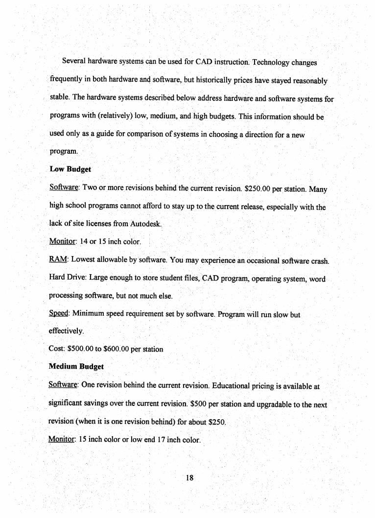
LowBudget
Software: Two or more revisions behind the current revision. $250.00 per station. Many
high school programs cannot afford to stay up to the current release, especially with the
Ijack of site licenses from Autodesk,
Monitor: 14 or 15 inch color.
RAM: Lowest allowable by software. You may experience ah occasional software crash.
Hard Drive. Large enough to store student files, CAD program, operating system, word
processing software, but not much else.
Speed: Minimum speed requirement set by software. Program will run slow but
effectively.
Cost: $500.00 to $600.00 per station
Medium Budget
Software: One revision behind the current revision. Educational pricing is available at
significant savings over the current revision. $500 per station and upgradable to the next
revision (when it is one revision behind) for about $250.
Monitor: 15 inch color or low end 17 inch color.
18
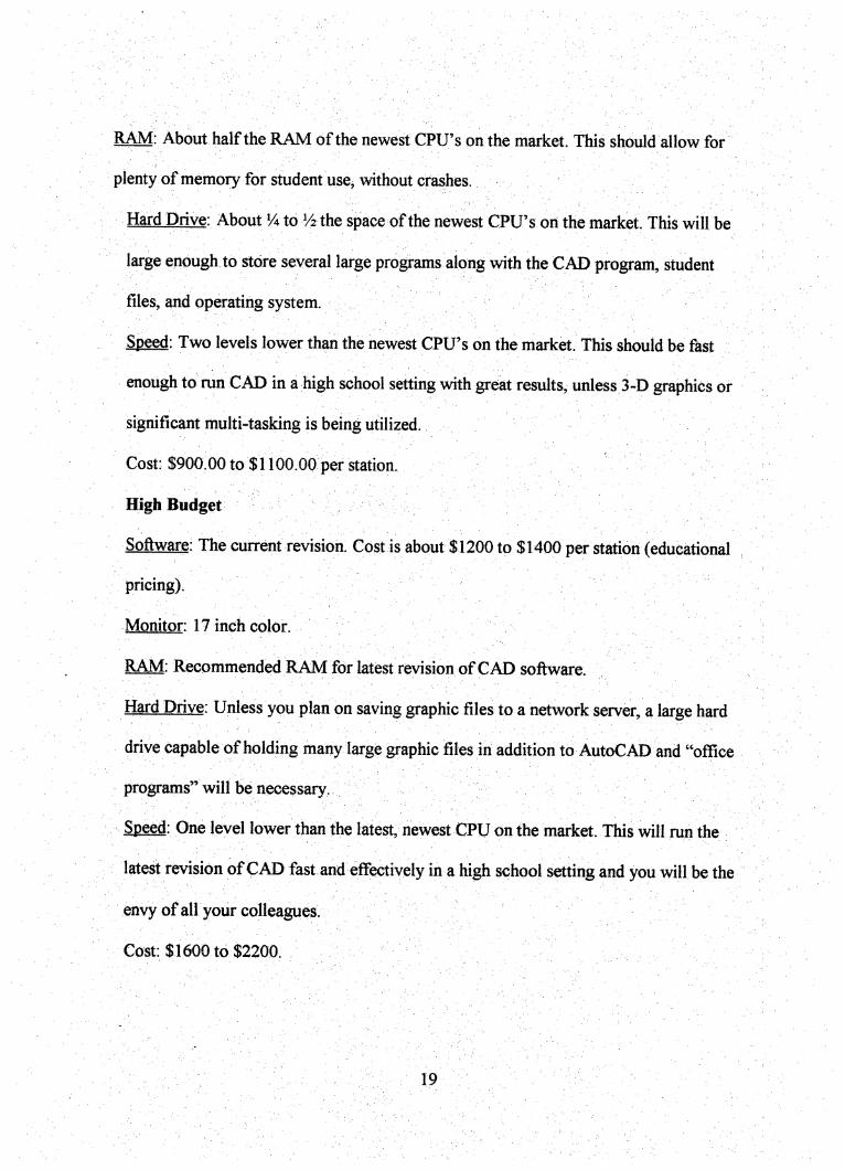
RAM: About half the RAM of the newest CPU's on the market. This should allow for
plenty of memory for student use, Avithout crashes.
Hard Drive: About Ya to V2 the space of the newest CPU' s on the market. This will be
large enough to store several large programs along with the CAD program, student
files, and operating system.
Speed: Two levels lower th^ the newest CPU's on the market. This should be fast
enough to run CAD in a high school setting with great results, unless 3-D graphics or
significant multi-tasking is being utilized.
Cost: $900.00to $1100.00 per station.
HighBudgef
Software: The current revision. Cost is about $1200 to $1400 per station (educational
pricing). '
Monitor: 17 inch color.
RAM: Recommended RAM fdr latest revision of CAD software.
Hard Drive: Unless you plan on saving graphic files to a network server, a large hard
drive Capable of holding many fege graphic files in addition to AutoCAD and "office
programs" will be necessary.
Speed: One level lower than the latest, newest CPU on the market. This will run the
latest revision of CAD fast and effectively in a high school setting and you will be the
envy of all your colleagues.
Cost: $1600 to $2200.
19

Each school will have its unique considerations when deciding oh hardware and
software. Prices have historically stayed fairly consistent while product capability has
increased exponentially. It is a true dilemma to attempt to stay "current" yet serve as
many students as possible with the money accessible for technology. Industry policy
imitation does not assist in the decision because its objectives are more financially
based (productivity verses capital outlay) than the typical public school, Educators
must remember their main objective is to meet the Comprehensive educational needs of
all their students.
20
Chapter Five: Summary
Introduction
Textbooks presently on the market do not, by themselves meet the needs of high school
level CAD drafting students. Based on data obtained from questioning drafting teachers
across the state of California, a need for better high school CAD drafting texts exists. The
purpose of this project is to develop a cost-effective workbook for high school students
that incorporates age-appropriate drawing problems, design problems, and the critical
commands of CAD.
This resource will help students to meet performance objectives as outlined by the
California State Frameworks for Visual Communication-Drafting. With the new
dominance of computer assisted drafting as the preferred tool for drafting, students have
been given the additional responsibility of being proficient in the use of the CAD
software to make themselves marketable to industry. Students are also expected to be
aware of industry standards for drafting; the more they know, the more value they have in
the workplace.
It must be remembered that computer assisted drafting (CAD) is a tool for visual
communication. The high school's primary responsibility is to teach design techniques
and principles, communication techniques and principles, and then the software tool to do
it. By the time the students are employed by industry, several software revisions will have
passed, but the communication standards will be basically the same.
The manual is designed to accompany standard texts and especially to accompany
CAD texts. The CAD texts are comprehensive in their coverage of the software
21

commands and features, the manual is not designed to be a reference text. The CAD
texts are revision specific and must be re-written after each revision change. The manual
will be wntten so it does not have to be changed after each revision change, however as
software changes more dramatically, re-writes of the manual will follow,
Project Development
The challenge of creating drawing problems that addressed problem solving,
industry standards, AutoCAD commands, and incorporated cross-curricular instruction
was challenging. It was difficult to design the problem so that the student had to
creatively solve the problem, with a limited amount of hints, and still apply the correct
standards. It was also difficult to decide which order to introduce each AutoCAD
command. The student needed a working knowledge of each command to be used for a
drawing problem, before the problem could be solved. Concessions had to be made, such
as just telling them how to use a command (with explanation to follow).
A large challenge in preparing the manual was the importing of graphics The saying "a
picture tells a thousand words" certainly applied to this project. Although student
comprehension of technical literature (through practice) was a major goal of the manual,
some graphics were necessary for effective communication.
22
APPENDIX A: QUESTIONAIRE RESULTS
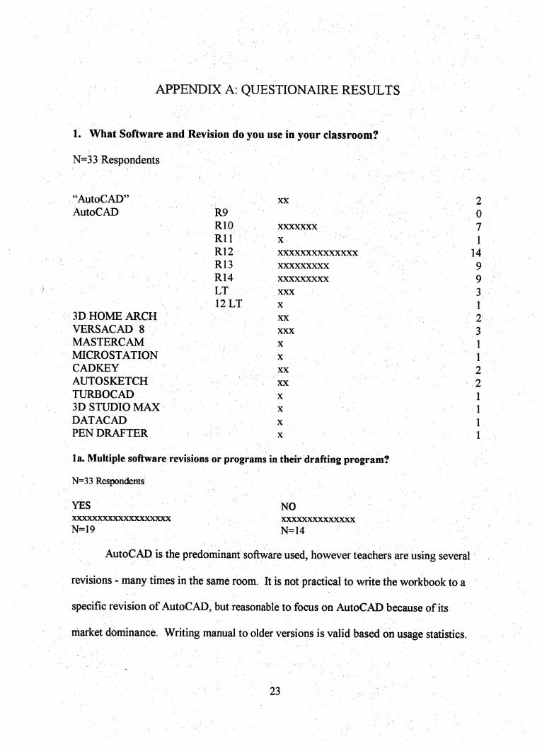
1. What Software and Revision do you use in your classroom?
N=33 Respondents
"AutoCAD'
AutoCAD
3D HOME ARCH
VERSACAD 8
MASTERCAM
MICROSTATION
CADKEY
AUTOSKETCH
TURBOCAD
3D STUDIO MAX
DATACAD
PEN DRAFTER
XX
'R9- ;■RIO xxxxxxxRll ■ ■ XR12 xxxxxxxxxxxxxxR13 xxxxxxxxxR14 xxxxxxxxxLT XXX12 LT X
■ XX
XXX
X
' ■ ■ - . X . . . . ■ ■XX
XX
X
X
X
X
la. Multiple software revisions or programs in their drafting program?
N=33 Respondents
YESXXXXXXXXXXXXXXXXXXX
N=19
NOXXXXXXXXXXXXXX
N=14
20
7T
1499
31
2
31
1
221I
11
AutoCAD is the predominant software used, however teachers are using several
revisions - many times in the same room. It is not practical to write the workbook to a
specific revision of AutoCAD, but reasonable to focus on AutoCAD because of its
market dominance. Writing manual to older versions is valid based on usage statistics.
23

2. How many levels of subjects do you offer in a single period?
(EX: DRAFT A, ARCH A, ARCH B)
N=33 Responses
8 5 6 3 3 7 7 2 6 4 4
8 3 1 2 4 2 7 5 6 4 5
4 2 4 4 6 8 7 4 1 7 6
Courses have a mean average of 5.5 levels of students per program. The manual will need
to meet the needs of lower^eginning students as well as higher level students.
3. How many texts and supplemental texts do you use in your classroom?
N=32 Responses4 3 6 2 6 3 6 3
3 4 3 4 0 2 2 2
2 4 4 4 2 2 5 2
0 1 6 6 3 0 1 0
3.3 texts and supplemental texts per program.
4. Do you know of any textbooks for CAD that are specifically designed for high school students'
needs? If so, please list the name(s) and author(s).
N=33 Responses
* Applying AutoCad - Delmar
* Drafting w/ AutoCad LT - Chowenhill - Wallach
* Fundamentals of Drafting with Autocad LT-ITP
* AutoCad and its Applications R14 - Goodheart Wilcox
* Applying AutoCad - Wohlers
24
* Cad Key
* "Unknown Title: Masden - Goodheart Wilcox
*26 "NO" answers
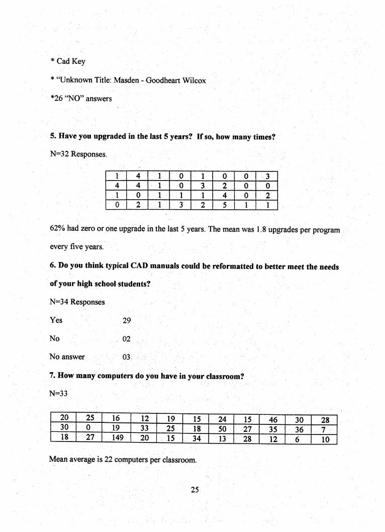
5. Have you upgraded in the last 5 years? If so, how many times?
N=32 Responses.
1 4 1 0 1 0 0 3
4 4 1 0 3 2 0 0
1 0 1 1 1 4 0 2
0 2 1 3 2 5 1 1
62% had zero or one upgrade in the last 5 years. The mean was 1.8 upgrades per program
every five years.
6i Do you think typical CAD manuals could be reformatted to better meet the needs
of your high school students?
N=34 Responses
Yes , ■ 19 ;
No. ■ 02,
No answer ^/■■ ■03.. '
7. How many computers do you have in your classroom?
N=33- '
20 25 16 12 19 15 24 15 46 30 2830 0 19 33 25 18 50 27 35 36 718 27 149 20 15 34 13 28 12 6 10
Mean average is 22 computers per classroom.
25
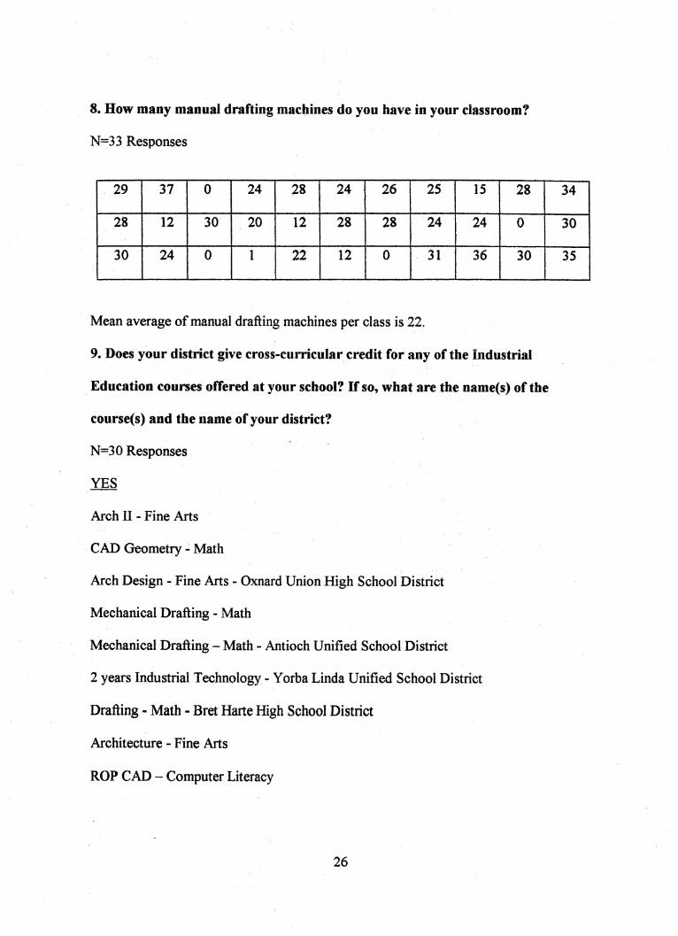
8. How many manual drafting machines do you have in your classroom?
N=33 Responses
29 37 0 24 28 24 26 25 15 28 34
28 12 30 20 12 28 28 24 24 0 30
30 24 0 1 22 12 0 31 36 30 35
Mean average of manual drafting machines per class is 22.
9. Does your district give cross-curricular credit for any of the Industrial
Education courses offered at your school? If so, what are the name(s) of the
course(s) and the name of your district?
N=30 Responses
YES
Arch II - Fine Arts
CAD Geometry - Math
Arch Design - Fine Arts - Oxnard Union High School District
Mechanical Drafting - Math
Mechanical Drafting - Math - Antioch Unified School District
2 years Industrial Technology - Yorba Linda Unified School District
Drafting - Math - Bret Harte High School District
Architecture - Fine Arts
ROP CAD - Computer Literacy
26

NO
22 Schools out of 30 did not have cross-curricular credit in their Industrial Education
department.
27

^ENDIX B: DESIGN DRAFTING
BY WILLIAM BROWN
28
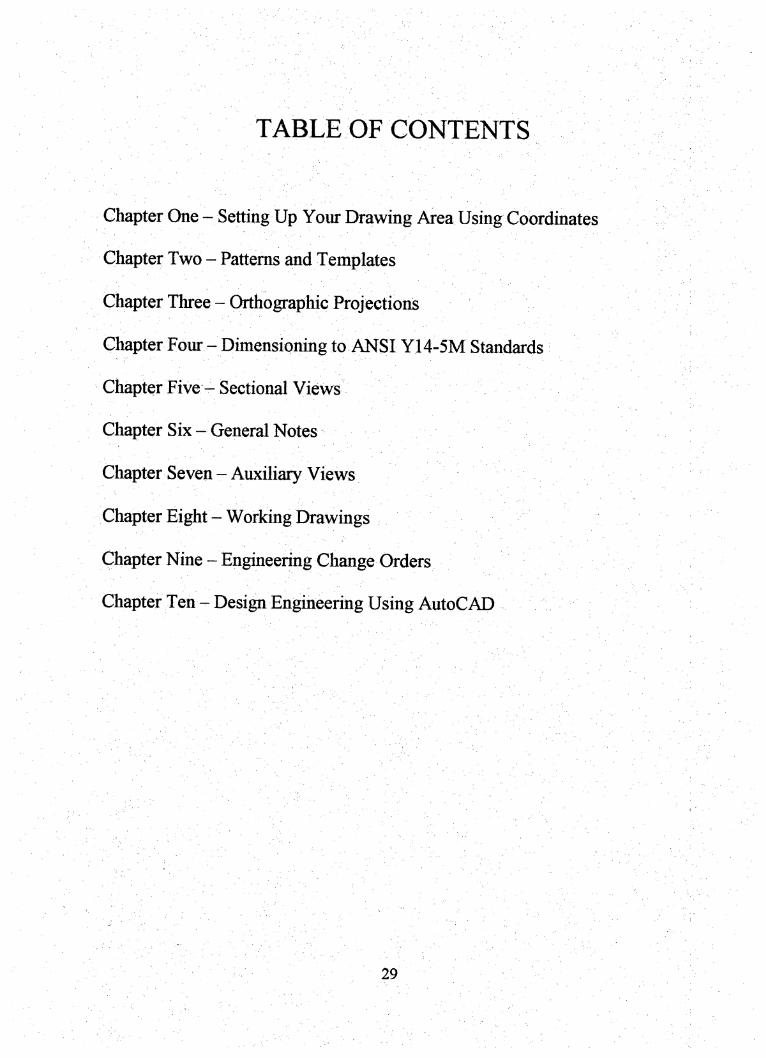
TABLE OF CONTENTS
Chapter One - Setting Up Your Drawing Area Using Coordinates
Chapter Two - Patterns and Templates
Chapter Three - Orthographic Projections
Chapter Four - Dimensioning to ANSI Y14-5M Standards
Chapter Five - Sectional Views
Chapter Six — General Notes
Chapter Seven - Auxiliary Views
Chapter Eight - Working Drawings
Chapter Nine - Engineering Change Orders
Chapter Ten - Design Engineering Using AutoCAD
29
CHAPTER ONE
SETTING UP YOUR DRAWING AREA
USING COORDINATES
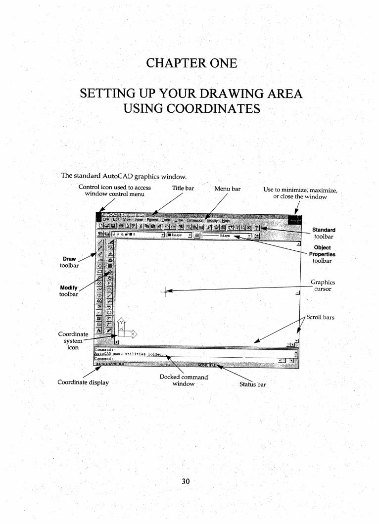
The standard AutoCAD graphics window.
Control icon used to access Title barwindow control menu
Menu bar
Draw ̂toolbar
Modifytoolbar
Coordinate
system'icon
Coordinate display
Use to minimize, maximize,or close the window
Standard
toolbar
yiew insert Farnfiot loqte Qtm <DimqasiQir
oinir mi y/i ̂Heto
3 JBByLayer jJ? rfB O avLayw
Coimaand:
AutoCAD menu utilities loadedCommand:
!4.47DB4375B.0Mli
Docked command
window
ObjectPropertiestoolbar
Graphics~ cursor
Scroll bars
Status bar
30
ChapterOne
Setting Up Your Drawing AreaUsing Coordinates
OBJECTIVES:
Upon completion of Chapter One, student will be able to:
• Utilize the Cartesian Coordinate System in AutoCAD.• Apply the concept of "scale" to drawing setup.• Differentiate between the absolute, relative, and polar coordinate systems
in AutoCAD.
• Identify paper sizes by ANSI Y14.1 standards.• Draw parts in AutoCAD that require scaling up and/or require scaling
down.
• Convert metric (millimeter) sizes to (decimal) inch sizes.
31
SETTING UP YOUR DRAWING AREA - USING COORDINATES
the drawing screen in AutoCAD uses the Cartesian coordinate system (the X-Y
axis) as a screen reference. If you move your mouse around the screen, you will notice a
pair of numbers moving. These are your coordinates. Notice as you move your mouse
horizontally to the right the first number gets bigger, That is your X-coordinate/ Notice as
you move your mouse vertically-up the second number gets bigger. That is your Y-
coordinate.
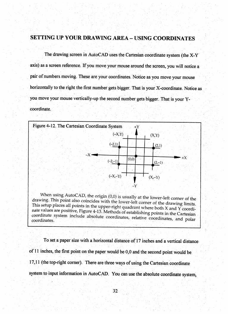
Figure 4-12. The Cartesian Coordinate System +Y
(-x,Y) ■iI . (x,Y) ;
^ " V ■ . '(-2:1)^1 A2,l)w i
I' ■ „
(0,0),(2,-1)
w ■
■ ■■■ ) ■ 16 1 1 (X,-Y)
-Y
When using AmoCAD, the origin (0,0) is usually at the lower-left corner of thetowmg. This pom also coincides with the lower-left comer of the draX hmhTTh« se up places all points in the upper-right quadrant where both X an^ Y cS^natewaiues are posibve. Figure 4-13. Methods of establishing points in the Qt^testancSrlSIJi '' coordinates, relative®cLdinates, aS potar
To set a paper size with a horizontal distance of 17 inches and a vertical distance
of 11 inches, the first point on the paper would be 0,0 and the second point would be
17,11 (the top-right comer). There are three ways of using the Cartesian coordinate
system to input information in AutoCAD. You can use the absolute coordinate system^
32
the relative coordinate system, or the polar coordinate system. For the purposes of this
class, will work in the first quadrant, which is the upper right quarter of the axis system.
See Figure 4-12 and Figure 4-13.
Do Exercise 4-1 ABSOLUTE COORDINATES
Do Exercise 4-2 RELATIVE COORDINATES
Do Exercise 4-3 POLAR COORDINATES
(If the part you are drawing looks strange, check the command line to see if you forgot an
@ sign or a comma).
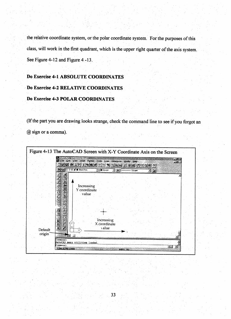
Figure 4-13 The AutoCAD Screen with X-Y Coordinate Axis on the Screen
Default
origin
iiijsw Famat lools Qraw Oimeftsian Modrly "aelp
DlBStBllLAlyl jsNlalrft "I"-!
j —g )■ prrrri;n;s ^ ajl- (gj XI
J
IncreasingY coordinate
value
+Increasing
X coordinate\ alue
Command:AutoCAD menu utilities loaded.Command:
■il23»S.M?Si aODte 1 MODEL »L£"icnr
1
33
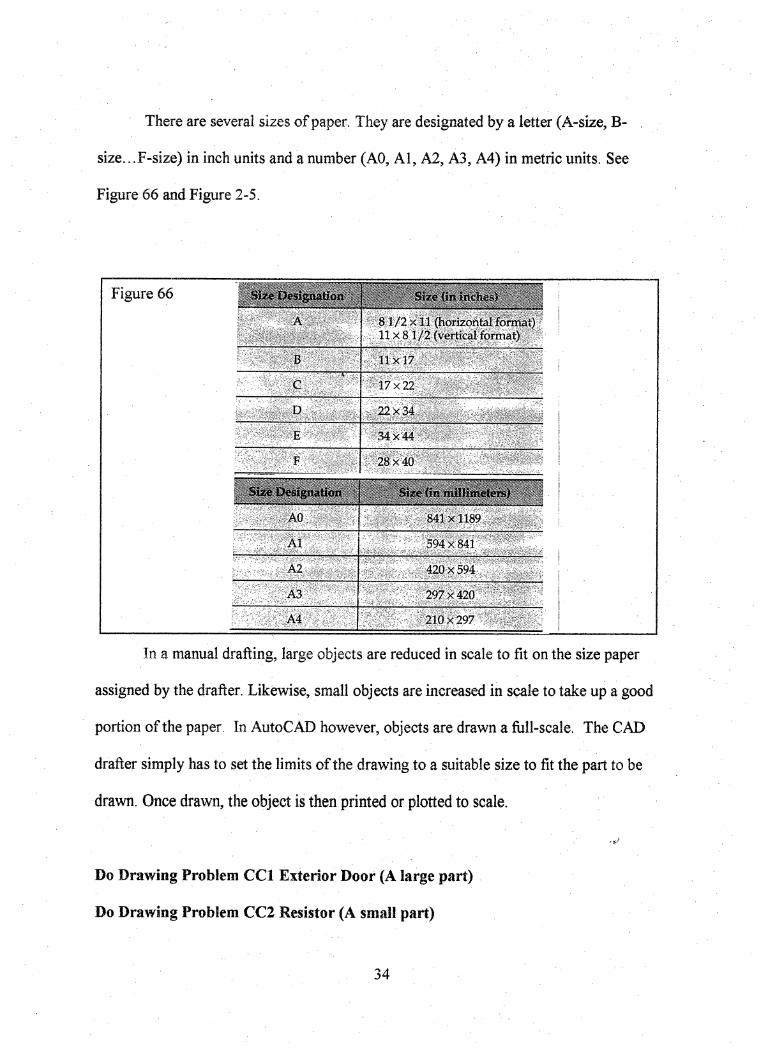
There are several sizes of paper. They are designated by a letter (A-size, B-
size.. .F-size) in inch units and a number (AO, Al, A2, A3, A4) in metric units. See
Figure 66 and Figure 2-5.
Figure 66
8 1/2 X11 (horizontal foiiiiat)11X 81/2 (vertical format)
B 11x17
c / 17x22 ' ' '
D 22 x 34 , , , :
34x44
28x40 ^
• ■
C"4A T\ * H
- ■
AO 841x1189 ^
Al 594x841
A2 420x594
A3 297 x 420
A4 210x297
In a manual drafting, large objects are reduced in scale to fit on the size paper
assigned by the drafter. Likewise, small objects are increased in scale to take up a good
portion of the paper. In AutoC AD however, objects are drawn a full-scale. The CAD
drafter simply has to set the limits of the drawing to a suitable size to fit the part to be
drawn. Once drawn, the object is then printed or plotted to scale.
Do Drawing Problem CCl Exterior Door (A large part)
Do Drawing Problem CC2 Resistor (A small part)
34

When drawing in metric, AutoCAD must be tricked into thinking it is drawing in
inches. Actually, AutoCAD "thinks" in decimal units not in inches or mm. Here is the
strategy. You want to draw a metric part with a length of200 mm and a height of a 100
mm. You want to plot on a B-size sheet, which is 17 X 11 inches. All AutoCAD
recognizes is 17 units by 11 units. 17 X 11 is certainly not big enough for a 200 by 100
part. So you adjust the limits. Multiply 17 by 25 equals 425 and multiply 11 by 25
equals 275. So that is (425,275). Those are your limits! Draw the parts full-size. Notice
the part fits with your new limits. When you're finished, you plot the drawing at 1/25
scale.
Do Drawing Problem CC3 TEMPLATE
The objective of this lesson was to introduce the Cartesian Coordinate System and
its application to setting up paper sizes (or drawing limits) and scaling drawings up and
scaling drawings down. Remember... we always draw the object/part fixll size: it is the
paper size we change (if necessary) to fit the part!
35
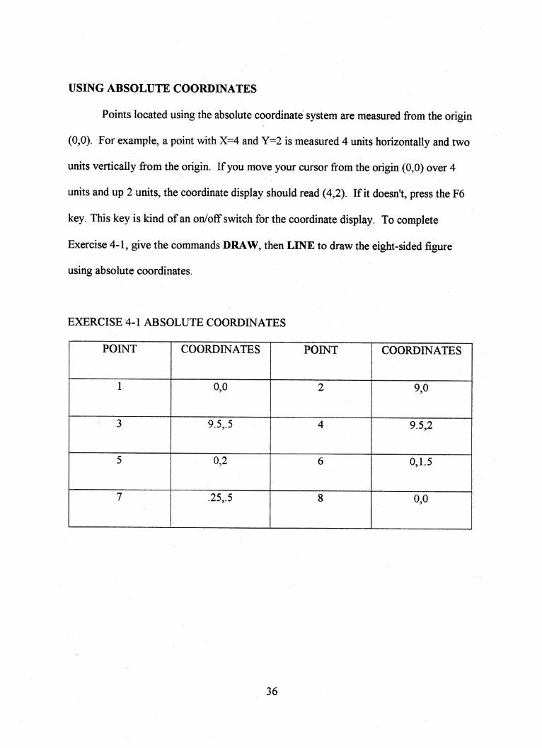
USING ABSOLUTE COORDINATES
Points located using the absolute coordinate system are measured from the origin
(0,0). For example, a point with X=4 and Y=2 is measured 4 units horizontally and two
units vertically from the origin. If you move your cursor from the origin (0,0) over 4
units and up 2 units, the coordinate display should read (4,2). If it doesn't, press the F6
key. This key is kind of an on/off switch for the coordinate display. To complete
Exercise 4-1, give the commands DRAW, then LINE to draw the eight-sided figure
using absolute coordinates.
EXERCISE 4-1 ABSOLUTE COORDINATES
POINT COORDINATES POINT COORDINATES
I 0,0 2 9,0
3 9.5,.5 4 9.5,2
5 0,2 6 0,1.5
7 .25,.5 8 0,0
36
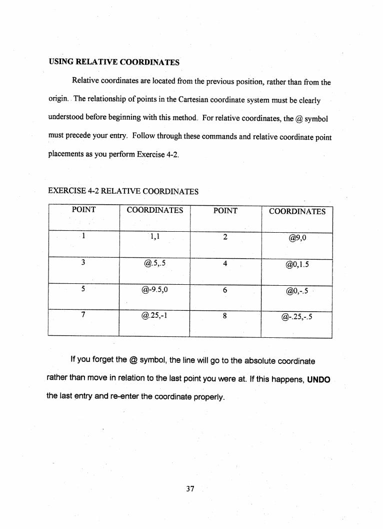
USING RELATIVE COORDINATES
Relative coordinates are located from the previous position, rather than from the
origin. The relationship of points in the Cartesian coordinate system must be clearly
understood before beginning with this method. For relative coordinates, the @ symbol
must precede your entry. Follow through these commands and relative coordinate point
placements as you perform Exercise 4-2.
EXERCISE 4-2 RELATIVE COORDINATES
POINT COORDINATES POINT COORDINATES
1 1,1 2 @9,0
3 @.5,.5 4 @0,1.5
5 @-9.5,0 6 @0,-.5
7 @.25,-1 8 @-.25,-.5
If you forget the @ symbol, the line will go to the absolute coordinate
rather than move in relation to the last point you were at. If this happens, UNDO
the last entry and re-enter the coordinate properly.
37
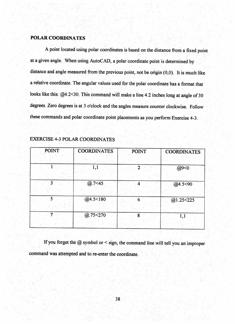
POLAR COORDINATES
A point located using polar coordinates is based on the distance from a fixed point
at a given angle. When using AutoCAD, a polar coordinate point is determined by
distance and angle measured from the previous point, not be origin (0,0). It is much like
a relative coordinate. The angular values used for the polar coordinate has a format that
looks like this: @4.2<30. This command will make a line 4.2 inches long at angle of 30
degrees. Zero degrees is at 3 o'clock and the angles measure counter clockwise. Follow
these commands and polar coordinate point placements as you perform Exercise 4-3.
EXERCISE 4-3 POLAR COORDINATES
POINT COORDINATES POINT COORDINATES
■ •: 1 ■ : ■ ■ 1,1 ■ 2 @9<0
■" ^ . @.7<45 : 4 @4.5<90
@4.5<180 6 , @1.25<225
;7 @.75<270 8 1,1
If you forget the @ symbol or < sign^ the command line will tell you an improper
command was attempted and to re-enter the coordinate.
38
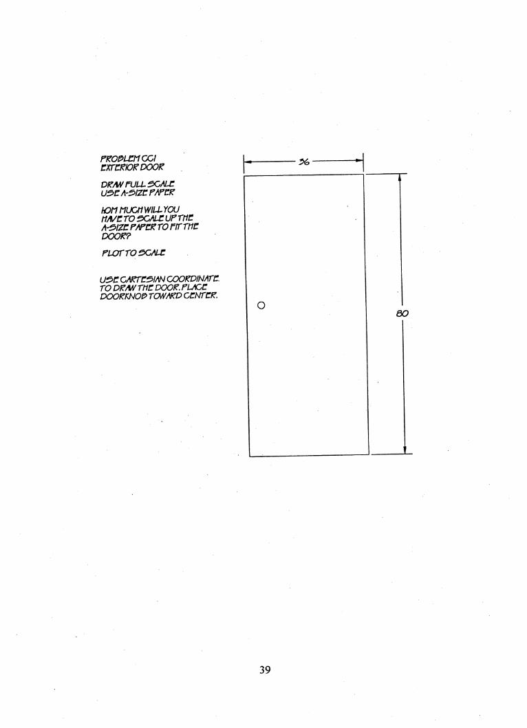
Pt^O^LCtKDOfCXrC^D^DOOK
fullscmj:US>CA-S>IZCF/FCF
hOtI MUCttWILLYOJtiA/cro scALCUprncA-S^ZCP/PCPTOrtTTIICDOOP?
fLOrrOSGALC
CAPTC^IAN COOPDINATC.TO DP/W rtic DOOP. PL/CCPOOPKNOP> rCWAPD CCNTCP.
OBO
39
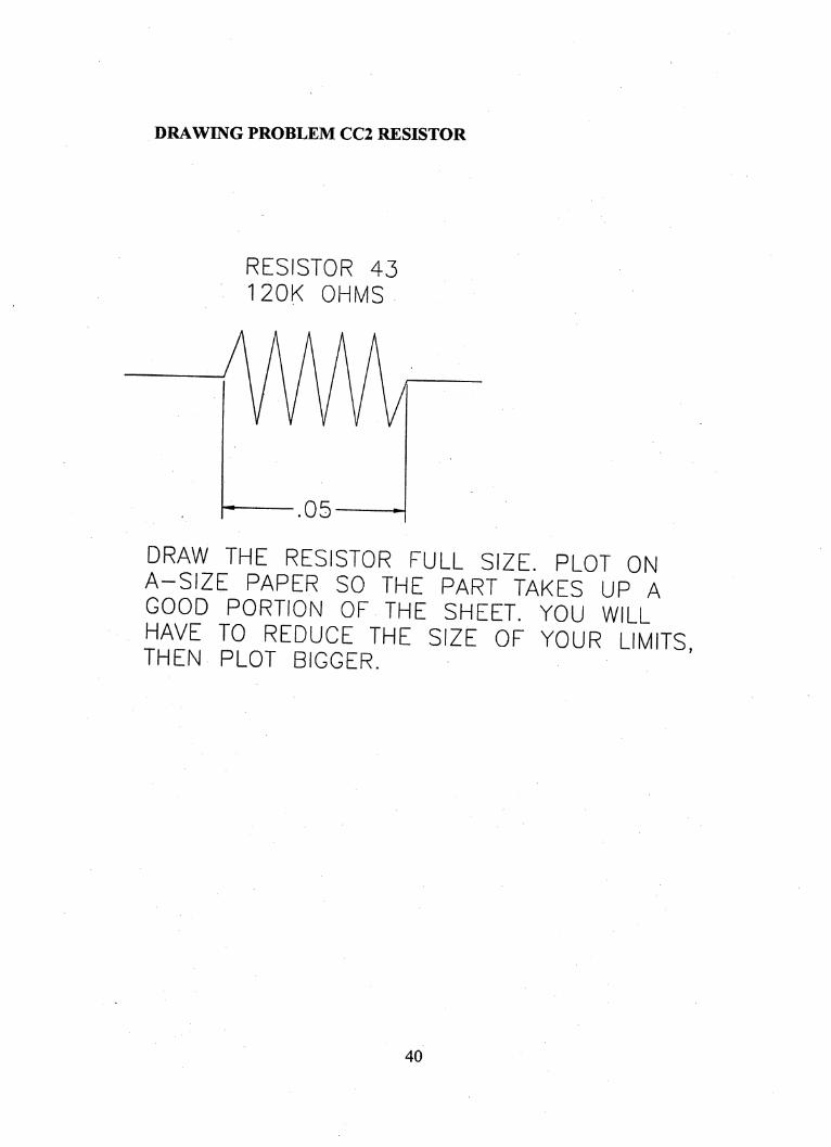
DRAWING PROBLEM CC2 RESISTOR
RESISTOR 43120K OHMS
.05
DRAW THE RESISTOR FULL SIZE. PLOT ONA-SIZE PAPER SO THE PART TAKES UP AGOOD PORTION OF THE SHEET. YOU WILLHAVE TO REDUCE THE SIZE OF YOUR LIMITSTHEN PLOT BIGGER. . '
40
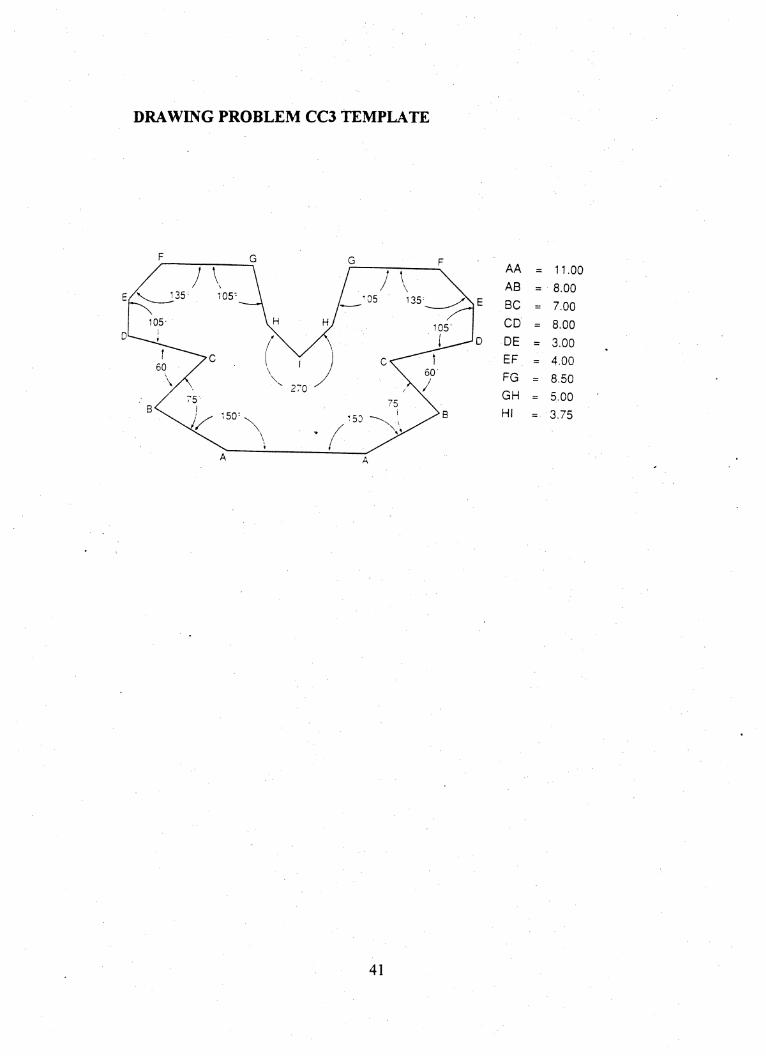
DRAWING PROBLEM CC3 TEMPLATE
135^ 105^ •05 135
105105"
6060-
270
BV i150
AA = 11.00
AB = 8.00
E BC .= 7.00
CD := 8.00
LJJQ
Q
= 3.00
EF == 4.00
FG == 8.50
GH == 5.00
HI =: 3.75
41
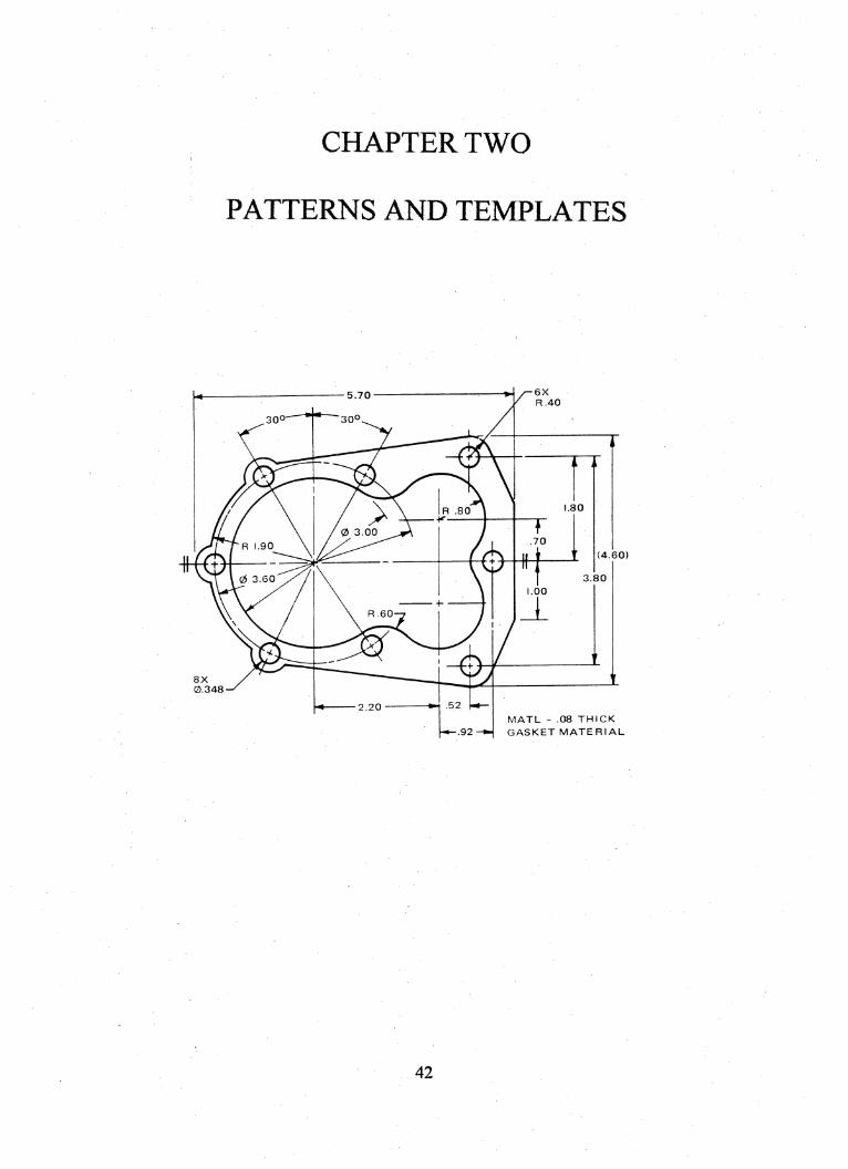
CHAPTER TWO
PATTERNS AND TEMPLATES
/-6X/ R.40
5.70
30° 30°
>8080
00.70
690
(4.60)
60 3.80
.00
60
6522.20
92
8X
0.348
MATL - .08 THICK
GASKET MATERIAL
42
GhapterTwo
Patterns and Templates
OBJECTIVES:
Upon completion of Chapter Two, student will be able to:
• Use the strategy of offsetting to layout parts.
• Draw parts in AutoCAD that are circular in nature.
• Apply the concept of "scale" to drawing setup.
• Identify metric drawing problems and adjust drawing set-up strategy to
accommodate metric measurement.
• Visualize metric units of length via estimation.
• Identify paper sizes by ANSI Y14.1 standards.
• Draw parts in AutoCAD that require scaling up and/or require scaling
down.
• Convert metric (millimeter) sizes to (decimal) inch sizes.
• Utilize additional AutoCAD commands.
• Use construction lines in drawing setup.
• Follow directions given in technical and/or mathematical vocabulary
43
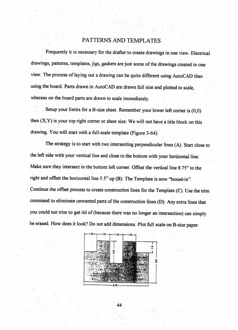
PATTERNS AND TEMPLATES
Frequently it is necessary for the drafter to create drawings in one view Electrical
drawings, patterns, templates, jigs, gaskets are just some of the drawings created in one
view. The process of laying out a drawing can be quite different using AutoCAD than
using the board. Parts drawn in AutoCAD are dravra full size and plotted to scale,
whereas on the board parts are drawn to scale immediately.
Setup your limits for a fi-size sheet. Remember your lower left comer is (0,0)
then (X,Y) is your top right comer or sheet size. We will not have a title block on this
drawing. You will start with a full-scale template (Figure 3-64).
The strategy is to start with two intersecting perpendicular lines (A). Start close to
the left side with your vertical line and close to the bottom with your horizontal line.
Make sure they intersect in the bottom left comer. Offset the vertical line 8.75" to the
right and offset the horizontal line 5.5" up (B). The Template is now "boxed-in".
Continue the offset process to create constmction lines for the Template (C). Use the trim
command to eliminate unwanted parts of the constmction lines (D). Any extra lines that
you could not trim to get rid of (because there was no longer ah intersection) can simply
be erased. How does it look? Do not add dimensions. Plot full scale on B-size paper.
1.75 — 1.75 — —1.75
T'.75
8.75
44
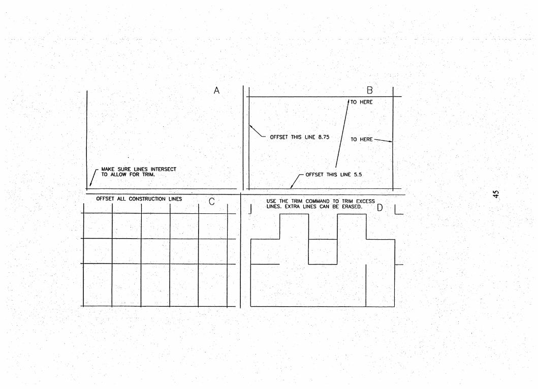
A
MAKE SURE LINES INTERSECTTO ALLOW FOR TRIM.
8
fTO HERE
OFFSET THIS LINE 8.75 / TO HERE-
OFFSET THIS LINE 5.5
OFFSET ALL CONSTRUCTION LINESc USE THE TRIM COMMAND TO TRIM EXCESS
LINES. EXTRA LINES CAN BE ERASED. Q
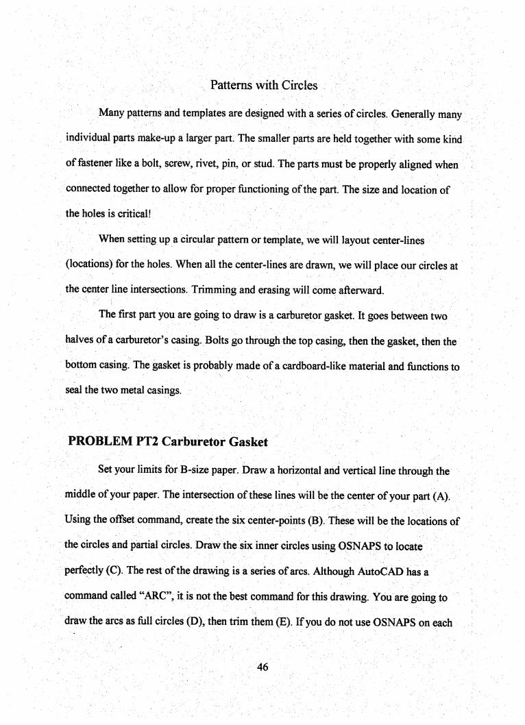
patterns with Circles
Many patterns and templates are designed with a series of circles. Generally many
individual parts make-up a larger part. The smaller parts are held together with some kind
of fastener likeabolt, screw, rivet, pin, or stud. The parts must be properly aligned when
Connected together to allow for proper functioning of the part. The size and location of
the holes is critical!
When setting up a circular pattern or template, we will layout center-lines
(locations) for the holes. When all the center-lines are drawn, we will place our circles at
the cpnter line intersections. Trimming and erasing will come afterward.
The first part you are going to draw is a carburetor gasket. It goes between two
halves of a carburetor's casing. Bolts go through the top casing, then the gasket, then the
bottom casing. The gasket is probably made of a cardboard-like material and functions to
seal the two metal casings.
PROBLEM PT2 Carburetor Gasket
Set your limits for B-size paper. Draw a horizontal and vertical line through the
middle of your paper. The intersection of these lines will be the center of your part (A).
Using the offset command, create the six center-points (fi). These will be the locations of
the circles and partial circles. Draw the six inner circles using QSNAPS to locate
perfectly (C)i The rest of the drawing is a series of arcs. Although AutoCAD has a
command called "ARC"^ it is not the best command for this drawing You are going to
draw the arcs as full circles (D), then trim them (E), If you do not use OSNAPS on each
46

circle, trimming will not work! Now your center-lines are probably a bit sloppy and do
not meet ANSI standards for center lines. Erase the center-lines (not the circles or arcs!).
Set DEVICEN at -.09. Type DIM then enter. Tj^e CE then enter. The command line
will prompt you to choose a circle or arc. Pick one! Hit enter. Pick another.. .This is a
much easier process than adjusting pre-made center lines within the circle. Fillet as
assigned. The drawing should look like (F).
Use the same strategy to do:
PROBLEM PT3 Angle Bracket
PROBLEM PT4 Identification Plate
47
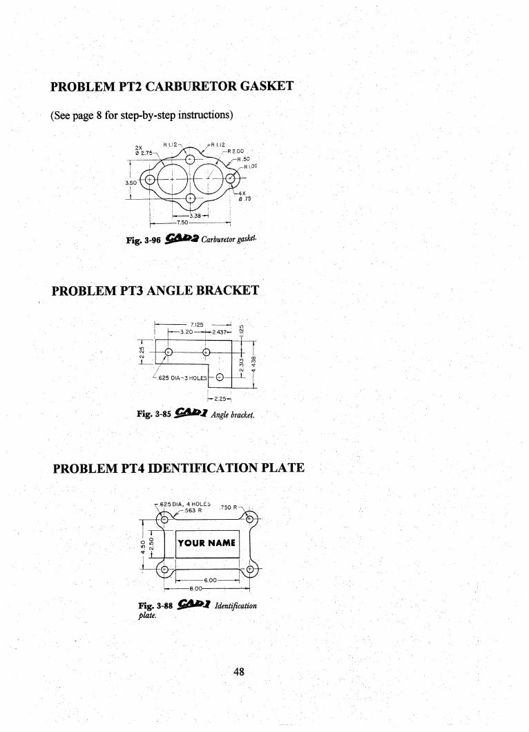
PROBLEM FT2 CARBURETOR GASKET
(See page 8 for step-by-step instructions)
0 2.75-^ ■ ArV\ . . .-RS.OOR.50
3.50
4X
0 .75
.38-H
7.50
Fig. 3-96 Carburetor gasket-
PROBLEM PT3 ANGLE BRACKET
7.125 lO
-3.20—-K 2.437-' ^
^^.625 DIA-3 HOLES -e-
C2 foro
oj
-2.25-
Fig. 3-85 Angle bracket.
PROBLEM PT4 IDENTIFICATION PLATE
.625 DIA, 4 HOLES563 R
,750 R
YOUR NAME
-6.00 -1
-8.00-
Fig. 3-88 Identijicatiiplate.
48
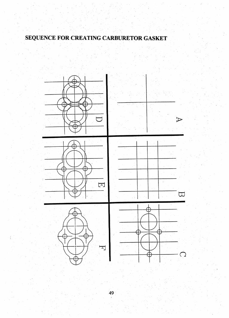
SEQUENCE FOR CREATING CARBURETOR GASKET
>
0
0tu
0
0 o
49
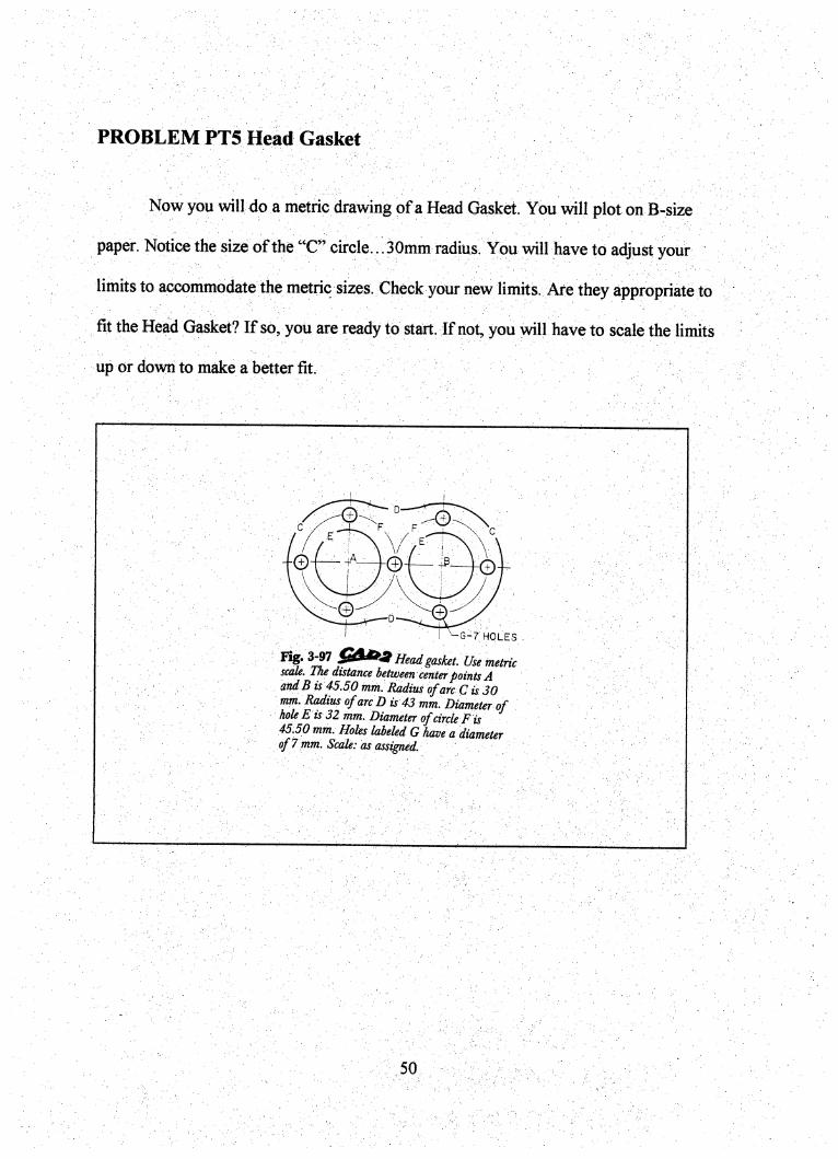
PROBLEM PT5 Head Gasket
Now you will do a metric drawing of a Head Gasket. You will plot on B-size
paper. Notice the size of the "C" circle... SQmm radius. You will have to adjust your
limits to accommodate the metric sizes. Check your new limits. Are they appropriate to
fit the Head Gasket? If so, you are ready to start. If not, you will have to scale the limits
up or down to make a better fit.
© © ©
G-7 holes .
Head gasket. Use metricscale. The distance between center points Aand B is 45.50 mm. Radius of arc C is 30nun. Radius of arc D is 43 mm. Diarneter ofhole E is 32 mm. Diameter of circle F is45.50 mm. Holes labeled G have a diameterof 7 rnm. Scale: as assigned.
50
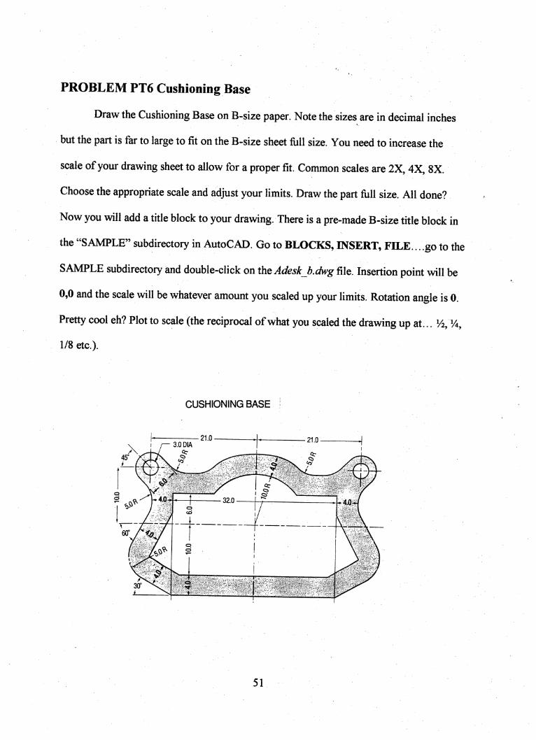
PROBLEM PT6 Cushioning Base
Draw the Cushioning Base on B-size paper. Note the sizes are in decimal inches
but the part is far to large to fit on the B-size sheet fiill size. You need to increase the
scale of your drawing sheet to allow for a proper fit. Common scales are 2X, 4X, 8X.
Choose the appropriate scale and adjust your limits. Draw the part full size. All done?
Now you will add a title block to your drawing. There is a pre-made B-size title block in
the "SAMPLE" subdirectory in AutoCAD. Go to BLOCKS, INSERT, FILE... go to the
SAMPLE subdirectory and double-click on ths Adesk b.dwg file. Insertion point will be
0,0 and the scale will be whatever amount you scaled up your limits. Rotation angle is 0.
Pretty cool eh? Plot to scale (the reciprocal of what you scaled the drawing up at... V2, Vi,
1/8 etc.).
CUSHIONING BASE
21.0 21.03.0 DA
4?
40 3Z0 AJ3
60" %
30*
51
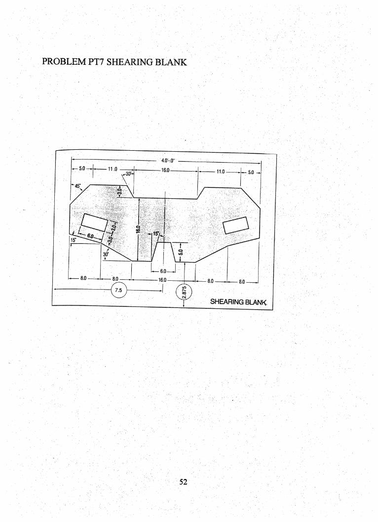
4.0'-0"
5.0 11.0 16.0 11.0 5.030^
45^
f\
C3tST/ I
15"
30°
L-6.0—J8.0 8.0 16.0 8.0 8.0
7.5
SHEARING BLANK
52
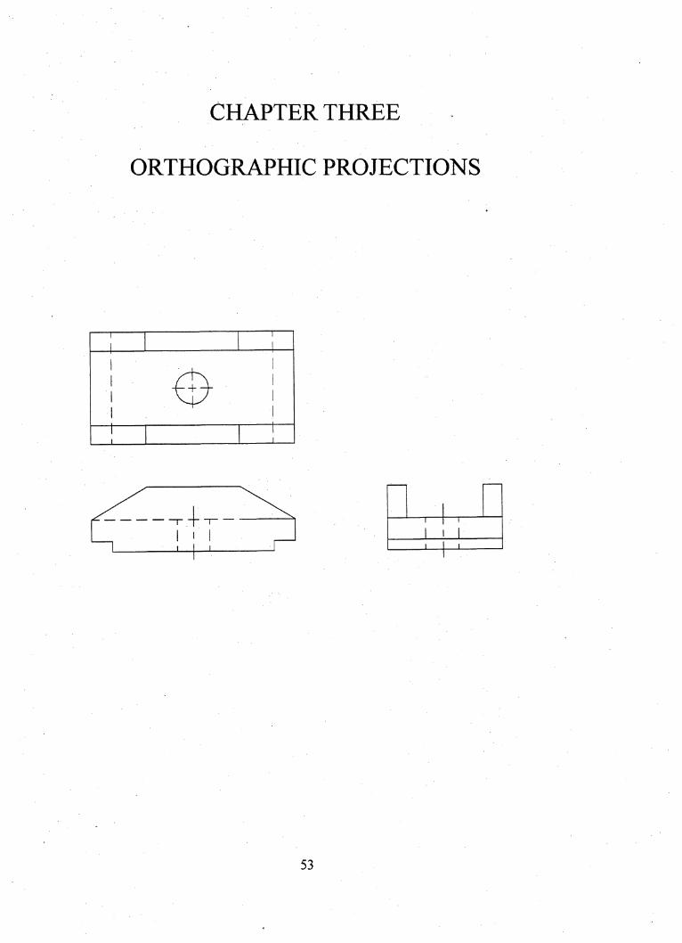
CHAPTER THREE
ORTHOGRAPHIC PROJECTIONS
T'i'T
53
Chapter 3
Orthographic Projections
OBJEGTIVES:
• Upon completion of Chapter Three, student will be able to:
• Identify and select the various views of an object.
size of an object.
Develop a multiview drawing/orthographic projection, utilizing
AutoCAD as a tool, to industry standards.
Place necessary hidden lines on views (for clarity).
technical literature.
54
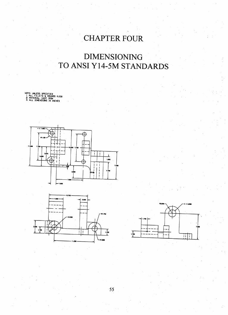
CHAPTER FOUR
DIMENSIONING
TO ANSI Y14-5M STANDARDS
NOTE. UNLESS SPECIFIED
i ̂ "BOUNDS R.250g. MATERIAL" CAST IRCW3. ALL DI«:NSIGNS IN INCHES
- J
"n
I
T"
■ HI -
-F-i-
e
T-^I I
laTso
*J»0
•3400
1.700
•1JOO11490
55
Chapter Four
Dimensioning
To ANSI Y14-5M Standards
OBJECTIVES:
Upon completion of Chapter Four, student will be able to:
• Apply measurements to technical drawings.
• Use ANSI Y14-5M standards for dimensions and notes.
• Differentiate between size dimensions and location dimensions.
• Dimension a part in decimal inch and/or metric.
• Utilize AutoCAD commands to apply dimensions.
• Demonstrate awareness of ANSI Y14-5M standards through research of
technical literature.
56
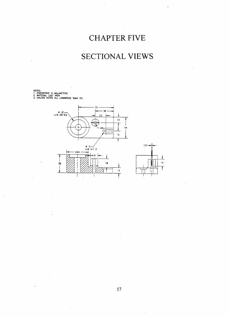
CHAPTER FIVE
SECTIONAL VIEWS
NOTES:1. DIMENSIONS IN MILLIMETERS2. MATERIAL- CAST IRON3. UNLESS NOTED ALL UNMARKED RADII R3
0 IE
28 ̂ 6
©t-
0 3u® 6t 3
f»44
®15
1 . ili■ w
f t r—^1 1 11 1
57
Chapter Five
Sectional Views
OBJECTIVES:
Upon completion of Chapter Five, student will be able to:
• Select the appropriate type of sectional view to show a hidden feature of
a part.
• Show ribs, webs, and fasteners, and similar features properly when the
cutting plane passes through them.
• Rotate certain features into the cutting plane.
• Utilize AutoCAD commands to apply section materials.
• Demonstrate awareness industry standards applying to sectioning,
through research of technical literature.
58
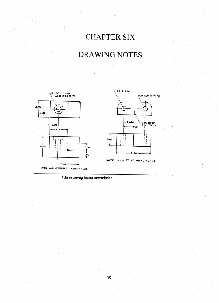
CHAPTER SIX
DRAWING NOTES
-0 1.00 ̂ THRU\ LJ 0 2.00 ̂ .75
4.00
r2.00
\
2.00
»—4.00-
5.0012.00
-7.00-
1.50
note: all unmarked radii - r .25
-2X R 1.50
2X 1.00 q? THRU
^2.44H ^SfiW KERF
500— -^5 DP.
3.00
!... 1 1
1' 1
1 1
(8.00)-^
NOTE : FAO TO 63 MICROINCHES
Notes on drawings improve communication
59

Chapter Six
Drawing Notes
OBJECTIVES:
Upon completion of this chapter, you will be able to:
• Apply notes on drawings to industry standards.
• Improve communication techniques using technical language.
• Differentiate between general notes and detail notes, and when to apply
each.
• Research technical literature involving notation.
60

NOTES ON DRAWINGS
A good drawing and may be defined as one that contains all of the information
required by the various design and manufacturing people who use it in producing the
subject part. In most of this information can be conveyed graphically, using standard
dimensioning practices. However, it is not uncommon to encounter a situation in which
all of the needed information cannot be communicated graphically. In these cases,
NOTES are used to communicate or clarify the designer's intent.
Notes are brief, carefully worded statements placed on drawings to convey
information not covered or not adequately explained using graphics. Notes should be
clearly worded so as to allow only one correct interpretation.
There are no ANSI standards specifically governing the use of notes on technical
drawings. However, several rules of a general nature should be observed. These rules
apply to both general notes and more specific detailed notes.
Two basic types of notes are used on technical drawings: general notes and
detailed notes.
General notes are broad items of information which have a job or project-wide
application rather than relating to just one single element of a project or part. General
notes are usually placed immediately above the title block on the drawing sheet and
numbered sequentially.
Information placed in general notes includes such characteristics of a product as
finish specifications; standard sizes of fillets, rounds, and radii; heat treatment
61

specifications; cleaning instructions; general toierancing data; hardness testing
instructions; and stamping specifications.
Detailed notes are specific notes that pertain to one particular element or
characteristic of a part. They are placed as near as possible to the characteristic to which
they apply, and are connected using a leader line.
Detailed notes should not be placed on views. Detailed notes also should never
be superimposed over other data such as dimensions, lines, or symbols. Use your
common sense on placement of notes when text/lettering space is at a premium.
A number of specifications should be observed when writing notes. Proper
lettering height is .250 inch titles such as general notes, and 3/16 inch for actual notes.
Spacing between lines of the same note should be .0625. Notes should be limited to four
to six words per line. Avoid a long line in a notes followed by one short line. Notes
should be expressed in the present tense. Notes should be positioned horizontally on the
drawing. The left end of all lines of a note should be in alignment, except when an
opening statement applies to several succeeding incomplete phrases. Abbreviated may be
used if there is no sacrifice in clarity. Do not specify fabrication operations (e.g., DRILL,
REAM, TAP, PUNCH, or BORE). The configuration, surface finish and/or tolerance
should permit MANUFACTURING to establish the type of operation. After all, that is
their expertise. NOT YOURS!
62

DEFINITIONS
General notes. General notes are those which apply to the drawing in general and
would become repetitive if placed at each point of application.
Indexed notes. The use of Delta notes are those which apply to specific
areas of the drawing or parts list in several locations and our cross-referenced by an index
symbol to the general notes.
Local notes. Local notes are those which apply directly to a particular portion of
a drawing, indicating local characteristics.
SEE THE PAGES AT THE END OF THIS CHAPTER (FROM
THE DRAWING REQUIREMENTS MANUAL) FOR MORE
SPECIFIC INFORMATION ON THE APPLICATION OF NOTES TO
YOUR DRAWING.
63
Placing Text on Drawings Using AutoCAD
Words and notes on drawings have traditionally been added by hand lettering.
This is a slow, time-consuming task. Computer-aided drafting programs have reduced
the tedious nature of adding notes to a drawing. In computer-aided drafting, lettering is
referred to as text.
Company standards often dictate how text appears on a drawing. The minimum
recommended text height on engineering drawings is .125". All dimension numbers,
notes, and other text information should be the same height. Titles, subtitles, captions,
revision information, and drawing numbers can be .188" to .25". Many companies
specify a .188 or 5/32" (5nim) lettering height for standard text. These text sizes are easy
to read even after the drawing is reduced,
Scale Factors for Text Height
Scale factors in text height should be determined before beginning a drawing, and
are best incorporated as values within your template drawing files. The scale factor is
multiplied by the desired plotted text height of the AutoCAD text height. The scale
factor is always a reciprocal of the drawing' s scale.
For example:
You will draw a car at scale of one inch equals one foot. That makes the scale
1/12. Your text needs to be 12 times larger than the size it will be plotted at. So. 125 text
64
would be set at a text height of. 125 X 12=1.5". Of course, the drawing will be plotted at
1/12 size, bringing the text-height down to normal size.
You will draw pen cap at 8X size. Your text needs to be 1/8 the size it will be
plotted at. So.l25 text would be set at atext height of .125 X 1/8= 1/64". Of course, the
drawing will be plotted at 8 times size, bringing the text-height up to normal size.
You will draw the floor plan of a home. The scale will be l/4"=r0". That makes
the scale T-4'0". That makes the scale 1"=48" or 1/48 size. What text height setting will
you use for an output text height of. 125 inches? Did you get six inches for an answer?
Fonts
A font is a particular letter face design. The TXT font is the AutoCAD default.
The .TXT font has a rather rugged appearance and may not be the best choice for your
application, even though the .TXT font requires less time to regenerate than other fonts.
The Romans (roman simplex) font is smoother. It closely duplicates the single stroke
gothic lettering that has long been the standard for most drafting. The complex and
triplex fonts are multi-stroke fonts for drawing titles and subtitles. The Gothic and italic
fonts are ornamental styles. In addition, AutoCAD provides several standard symbol
fonts.
65
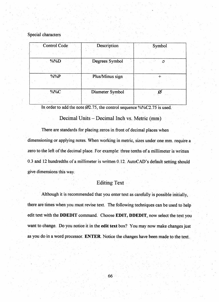
Special characters
Co^frolCode Description Symbol
%%D Degrees Symbol : o
%%P Plus/Minus sign +
%%C Diameter Symbol 0
In order to add the note 02.75, the control sequence %%C2.75 is used.
Decimal Units-Decimallnch VS. Metric (mm)
There are standards for placing zeros in front of decimal places when
dimensioning or applying notes. When working in metric, sizes under one mm. require a
zero to the left of the decimal place. For example: three tenths of a millimeter is written
0.3 and 12 hundredths of a millimeter is written 0.12. AutoCAD's default setting should
give dimensions this way.
Editing Text
Although it is recommended that you enter text as carefully is possible initially,
there are times when you must revise text. The following techniques can be used to help
edit text with the DDEDIT command. Choose EDIT, DDEDIT, now select the text you
want to change. Do you notice it in the edit text box? You may now make changes jiist
as you do in a word processor. ENTER. Notice the changes have been made to the text.
66
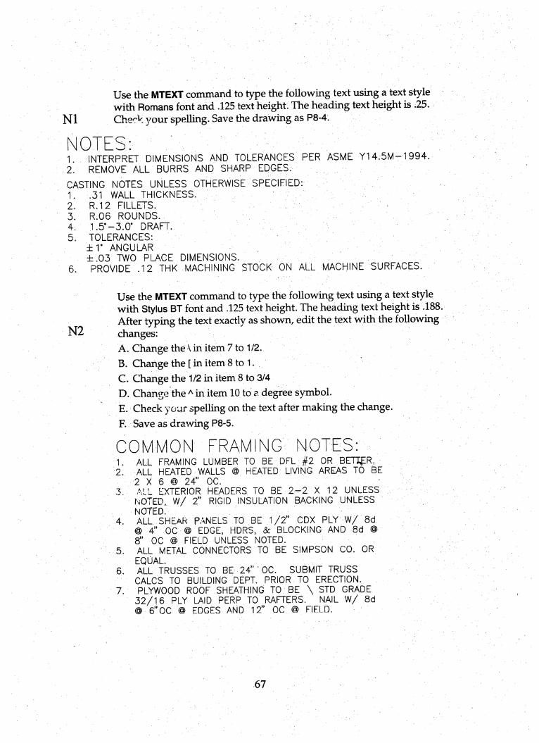
Use the MTEXT coininand to type the following text using a text stylewith Romans font and .125 text height. The heading text height is .25.
N1 Chec^" your spelling. Save the drawing as P8-4.
NOTES;1. INTERPRET DIMENSIONS AND TGLERANGES PER ASME Y14.5M-1994.2. REMOVE ALL BURRS AND SHARP EDGES.
CASTING NOTES UNLESS OTHERWISE SPEGIFIED;1. .31 WALL THICKNESS.2. R.I2 FILLETS.3. R.06 ROUNDS.4. 1.5°-3.0* DRAFT.5. TOLERANCES:
±r ANGULAR
±.03 TWO PLAGE DIMENSIONS.6. PROVIDE .12 THK MACHINING STOCK ON ALL MACHINE SURFACES.
Use the MTEXT command to type the following text using a text stylewith Stylus BT font and .125 text height. The heading text height is .188.After tj^ing the text exactly as shown, edit the text with the following
N2 changes:A. Change the \ in item 7 to 1/2.
B. Change the [ in item 8 to 1.C . Change the 1/2 in item 8 to 3/4
D. Change the ̂ in item 10 to a degree symbol.E. Check your spelling on the text after making the change.
R Save as drawing P8-5.
COMMON FRAMINGV NOTES: .1. ALL FRAMING LUMBER TO BE DEL #2 OR BEU^R.2. ALL HEATED WALLS @ HEATED LIVING AREAS TO BE
2 X 6 @ 24" OG.3. ALL EXTERIOR HEADERS TO BE 2-2 X 12 UNLESS T
noted, W/ 2" RIGID INSULATION BACKING UNLESSNOTED.
4. ALL SHEAR PANELS TO BE 1/2" GDX PLY W/ 8d@ 4" 00 @ EDGE, HDRS, & BLOCKING AND 8d @8" OC @ FIELD UNLESS NOTED.
5. ALL METAL CONNECTORS TO BE SIMPSON CO. OREQUAL
6. ALL TRUSSES TO BE 24" • OC. SUBMIT TRUSSCALCS TO BUILDING DEPT. PRIOR TO ERECTION.
7. PLYWOOD ROOF SHEATHING TO BE \ STD GRADE32/16 PLY LAID PERP TO RAFTERS. NAIL W/ 8d@ 6"0C @ EDGES AND 12" OC @ FIELD.
67
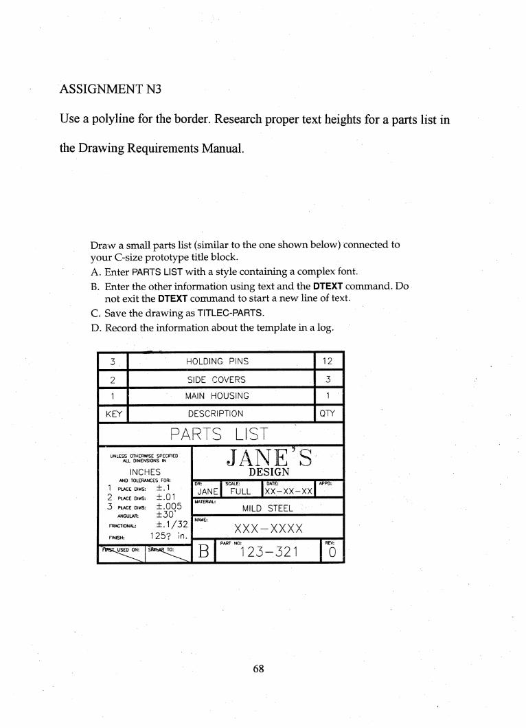
ASSIGNMENT N3
Use a polyline for the border. Research proper text heights for a parts list in
the Drawing Requirements Manual.
Draw a small parts list (similar to the one shown below) connected toyour C-size prototype title block.
A. Enter PARTS LIST with a style containing a complex font.
B. Enter the other information using text and the DTEXT command. Donot exit the DTEXT command to start a new line of text.
C. Save the drawing as TITLEC-PARTS.
D. Record the information about the template in a log.
HOLDING PINS 12
SIDE COVERS
MAIN HOUSING
KEY DESCRIPTION QTY
PARTS LIST
UNLESS OTHERWISE SPECIREDALL DIMENSIONS IN
INCHESAND TOLERANCES , FOR:
1 PLACE DIMS: ±. 1
2 PLACE DIMS:
3 PLACE DIMS:ANGULAR:
FT?ACTI0NAL:
±.01
±.005±30'±.1/3
RNISH:
21 25? in.
JANE SDESIGN
DR:
JANE
SCALE:
FULL
DATE:
xx-xx-xx
MILD STEEL
XXX-XXXX
B 123-321 0
68
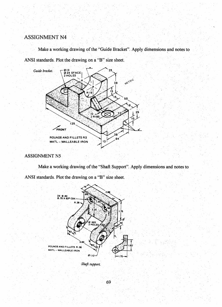
ASSIGNMENTS .
Make a working drawing of the "Guide Bracket" Apply dimensions and notes to
ANSI standards. Plot the drawing on a "B" size sheet.
Guide bracket. 0130 24 SPACE
25
2 HOLES
38
R 19
50
25
2RIBS
125
FRONT
38
64ROUNDS AND FILLETS R2
MATL- MALLEABLE (RON
ASSIGNMENTN5
Make a working drawing of the "Shaft Support". Apply dimensions and notes to
ANSI standards. Plot the drawing on a "B" size sheet
2X 0.40
0.75X82O CSk
ROUNDS AND FILLETS R .06
MAIL- MALLEABLE IRON
2.88
R.38
2.251.75
ar 502 r2 HOLEsXsoii!^^:::-
3.00
0 1.12
Shaft support
T
(0^ 1.82
1
f^l.75-^
69
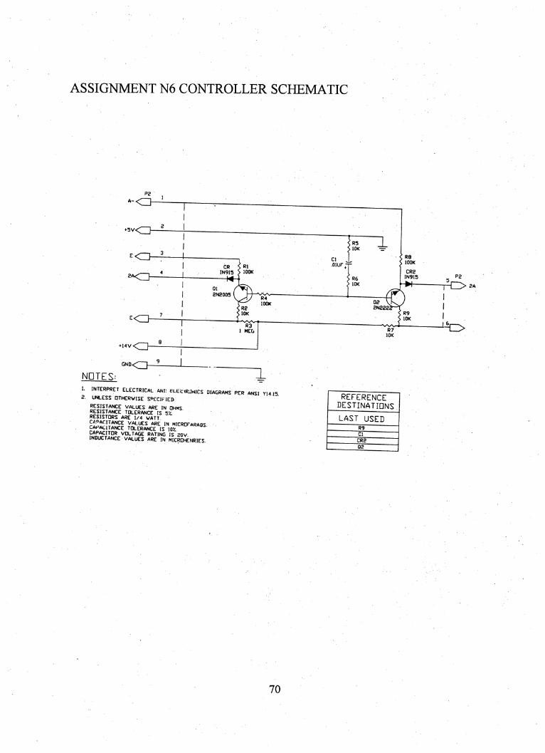
ASSIGNMENT N6 CONTROLLER SCHEMATIC
P2
■<J-
»5V<3-
^<11-
+ 14V<23-
GND< }-
NOTES:
CR S R1IN915 > lOOK
2N2005
lOOK
lOK
R3I MEG
C1 .•OIUF-
^R5> lOK
> R6► lOK
J.
2N222
lOK
v'S/V
lOK
< R8< lOOK
CR2IN9I5
5
I M
P2
1_interpret electrical anf; blecirmcs diagrams per ANSI YI4 15unless DTHERWISE SPECif lED:
VALUES ARE IN OHMS.resistance tolerance IS 5'/..RESISTORS ARE 1/4 WATT.CAPACITANCE VALUES ARE IN MICROFARADScapacitance tolerance is 10*/.
'BATING IS 20V.INDUCTANCE VALUES ARE IN MICROHENRIES.
REFERENCEdestinationsLAST USED
70
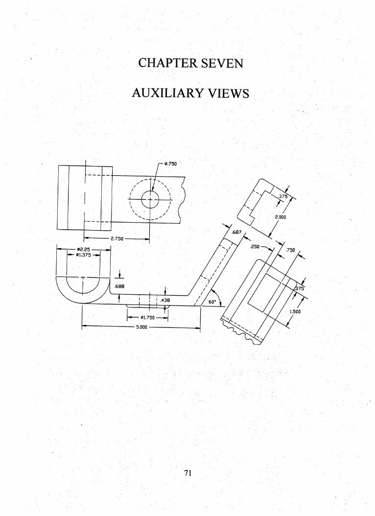
CHAPTER SEVEN
AUXILIARY VIEWS
/ ^ // I A C/ ̂X \ A
1 {
' (\ ̂
1 ' /'
\ VV ̂
J 1 /-/ / /
A / (SV.
/ V>' V,
375
2.000
687
250«2.25 750
01.375 —»•
_L.688
75
L ' I! 1 ! w
60
1.500
01.750
— 5.000 —
71
Chapter Seven
Auxiliary Views
OBJECTIVES:
Upon completion of Chapter Seven, student will be able to:
• Develop a primary auxiliary view of an inclined surface.
• Determine when a partial auxiliary view is acceptable and when a
complete auxiliary view is required.
• Utilize AutoCAD commands to develop an auxiliary view.
• Demonstrate awareness industry standards regarding auxiliary views,
through research of technical literature.
• Apply proper dimensioning techniques to auxiliary views.
72
CHAPTER EIGHT
WORKING DRAWINGS
ftEVlSION
£ca ncscpiPTitu DATEA PWHJUCTION RELEASf: 5-2l-fl7
aa Of UATERtALS
7 90LT AND HEXNUT 1 STK .313 X 1.3
6 STEEL BALI 1 STl J13 OU
9 SWVEL BUTTON 1CRS 1X 1
4 SWWEL f CRS 1 X .7
3 THUMB SOttW 1 CRS 1 X 1.1B3
. 2 BASE 1 CRS 2.7S X 11 X .75
1 HEAD 1 Cl 1.629 X 6.5 X 3.313ITEM MIT MATERIN. REMARKS i
73

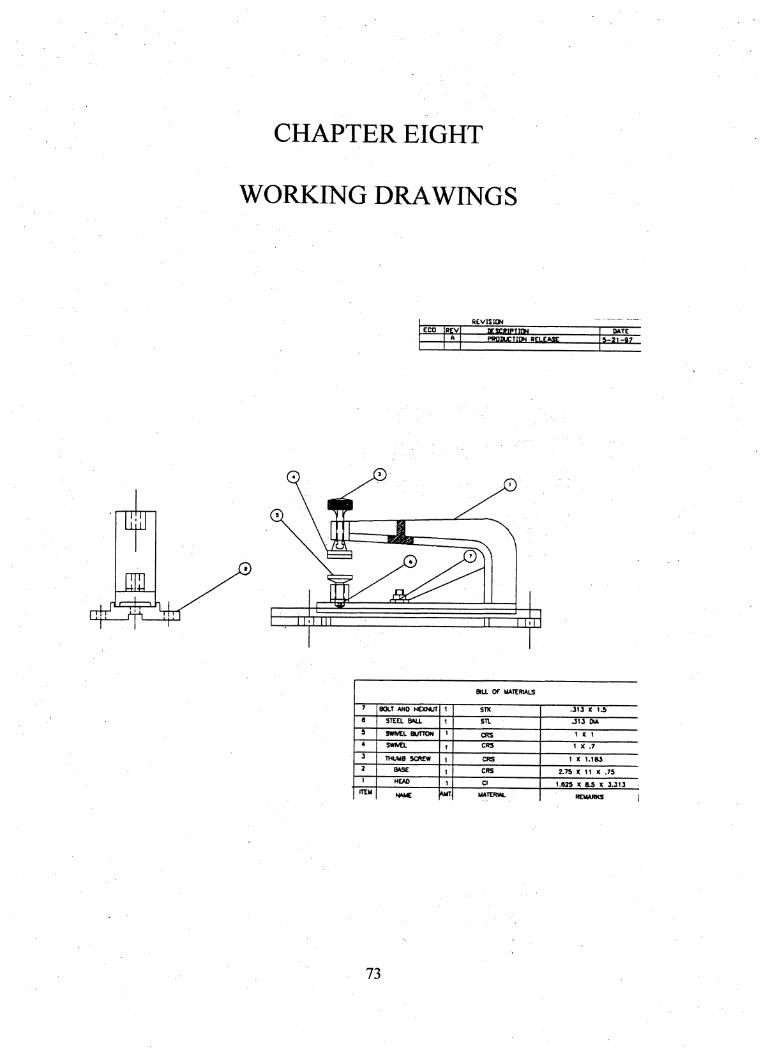
Chapter Eight
Working Drawings
OBJECTIVES:
• Upon completion of Chapter Eight, student will be able to:
• Describe and produce detail drawings, assembly drawings, and assembly
working drawings.
• Develop a bill of materials and parts list for a working drawing.
• Apply reference symbols to parts per industry standards.
• Identify the relationship between connecting parts through dimensions
and function.
• Complete a challenging working drawing, to industry standards, utilizing
AutoCAD as a drawing tool.
74

CHAPTER NINE
ENGINEERING CHANGE ORDERS (ECO'S)OR
DRAWING CHANGE PROCEDURES
75

Chapter Nine
Engineering Change Orders (EGO'S)or ■
Drawing Change Procedures
OBJECTIVES:
Upon completion of Chapter Nine, student will be able to:
• Complete an Engineering Change Order form.
• Identify the process used to generate an ECO.
• Record change orders on an engineering drawing to industry standards.
• Research industry documentation on proper standards to complete an
■ ECO.' ■
• Make appropriate changes to a drawing by following instructions on an
ECO form.
76

Engineering Change Orders (ECO)or Drawing Change Procedure (DC?)
When a drawing needs to be changed from the original release or revision, a
document called an Engineering Change Order (ECO) must be created. This chapter will
discuss techniques and procedures involved in making revisions requested from an ECO
to your engineering drawings .
When a drawing, or set of drawings are created by a design drafler or engineer,
the drawing(s) are released to every sector in the company involved in making/producing
the part. The initial drawing everybody receives would be Revision A. If the part works
fine, everyone is happy and no more revisions need to be generated. Frequently however,
parts can be redesigned to better meet their function. This decision to redesign the parts
could come from the customer, the manufacturing department, purchasing department,
the quality control department, the sales force, or the engineering department. Whoever
initiates the change does so by creating an Engineering Change Order (ECO). This ECO
basically states what the change should be and why the change(s) is being requested. The
ECO only needs to be generated if the drawing has actually been released.
The responsible engineer has the primary responsibility for initiating ECO's or for
approving ECO's originated outside the project. On receipt of an approved ECO, the
drafting department determines the correct procedure for implementing the change(s). A
pre-printed form is used to authorize and record drawing changes. T5q)ing or legible
hand lettering is permissible on this form.
77

Once changes are made to the original revision (A), the drawing now becomes
Revision B. Subsequently, if changes are made to revision B, the drawing becomes
Revision C... A drawing may have many revisions. Multiple changes (two or more) to
the same drawing and incorporated at one time shall be identified by the same revision
letter and may be identified on the ECO in numerical sequence and on the field of the
drawing enclosed in the revisions symbol balloon as a suffix number.
The following sheets shown ECO's and the procedures that must be followed
when generating Engineering Change Orders. Note page 23-7 for placement and format
of the Engineering Change Orders on the drawing.
78
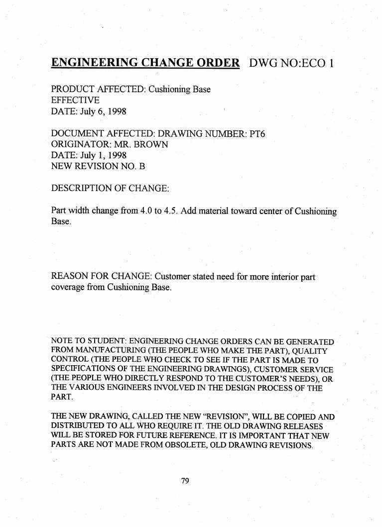
ENGINEERING CHANGE ORDER DWG NO:ECO 1
PRODUCT AFFECTED; Cushioning BaseEFFECTIVE
DATE: July 6, 1998
DOCUMENT AFFECTED: DRAWING NUMBER: PT6
ORIGINATOR: MR. BROWN
DATE: July 1, 1998NEW REVISION NO. B
DESCRIPTION OF CHANGE:
Part width change from 4.0 to 4.5. Add material toward center of CushioningBase.
REASON FOR CHANGE: Customer stated need for more interior partcoverage from Cushioning Base.
NOTE TO STUDENT: ENGINEERING CHANGE ORDERS CAN BE GENERATEDFROM MANUFACTURING (THE PEOPLE WHO MAKE THE PART), QUALITYCONTROL (THE PEOPLE WHO CHECK TO SEE IF THE PART IS MADE TOSPECIFICATIONS OF THE ENGINEERING DRAWINGS), CUSTOMER SERVICE(THE PEOPLE WHO DIRECTLY RESPOND TO THE CUSTOMER'S NEEDS), ORTHE VARIOUS ENGINEERS INVOLVED IN THE DESIGN PROCESS OF THE
PART.
THE NEW DRAWING, CALLED THE NEW "REVISION", WILL BE COPIED ANDDISTRIBUTED TO ALL WHO REQUIRE IT. THE OLD DRAWING RELEASESWILL BE STORED FOR FUTURE REFERENCE. IT IS IMPORTANT THAT NEWPARTS ARE NOT MADE FROM OBSOLETE, OLD DRAWING REVISIONS.
79
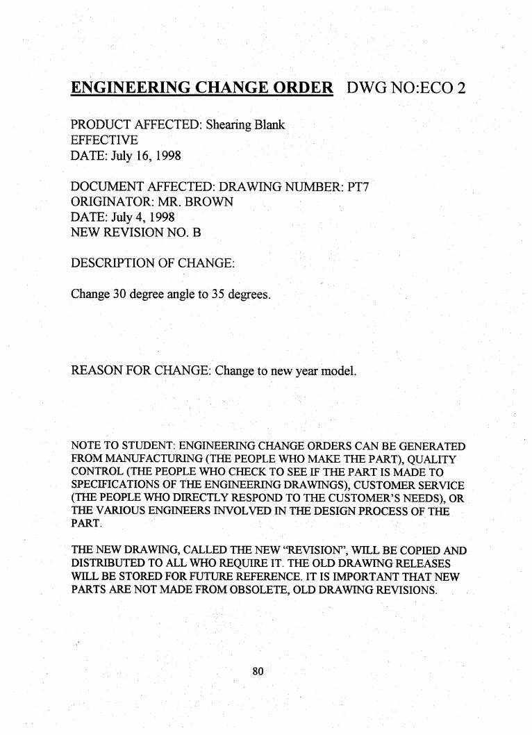
ENGINEERING CHANGE ORDER DWGN0:EC0 2
PRODUCT AFFECTED: Shearing BlankEFFECTIVE
DATEiJuly 16, 1998
DOCUMENT AFFECTED: DRAWING NUMBER: PT7
ORIGINATOR: MR. BROWN
DATE: July 4,1998NEW REVISION NO. B
DESCRIPTION OF CHANGE:
Change 30 degree angle to 35 degrees.
REASON FOR CHANGE: Change to new year model.
NOTE TO STUDENT: ENGMERING CHANGE ORDERS CAN BE GENERATED
FROM MANUFACTURING (THE PEOPLE WHO MAKE THE PART), QUALITYCONTROL (THE PEOPLE WHO CHECK TO SEE IF THE PART IS MADE TOSPECIFICATIONS OF THE ENGINEERING DRAWINGS), CUSTOMER SERVICE(THE PEOPLE WHO DIRECTLY RESPOND TO THE CUSTOMER'S NEEDS), ORTHE VARIOUS ENGINEERS INVOLVED IN THE DESIGN PROCESS OF THE
PART.
THE NEW DRAWING, CALLED THE NEW "REVISION', WILL BE COPIED ANDDISTRIBUTED TO ALL WHO REQUIRE IT. THE OLD DRAWING RELEASESWILL BE STORED FOR FUTURE REFERENCE. IT IS IMPORTANT THAT NEW
PARTS ARE NOT MADE FROM OBSOLETE, OLD DRAWING REVISIONS.
80
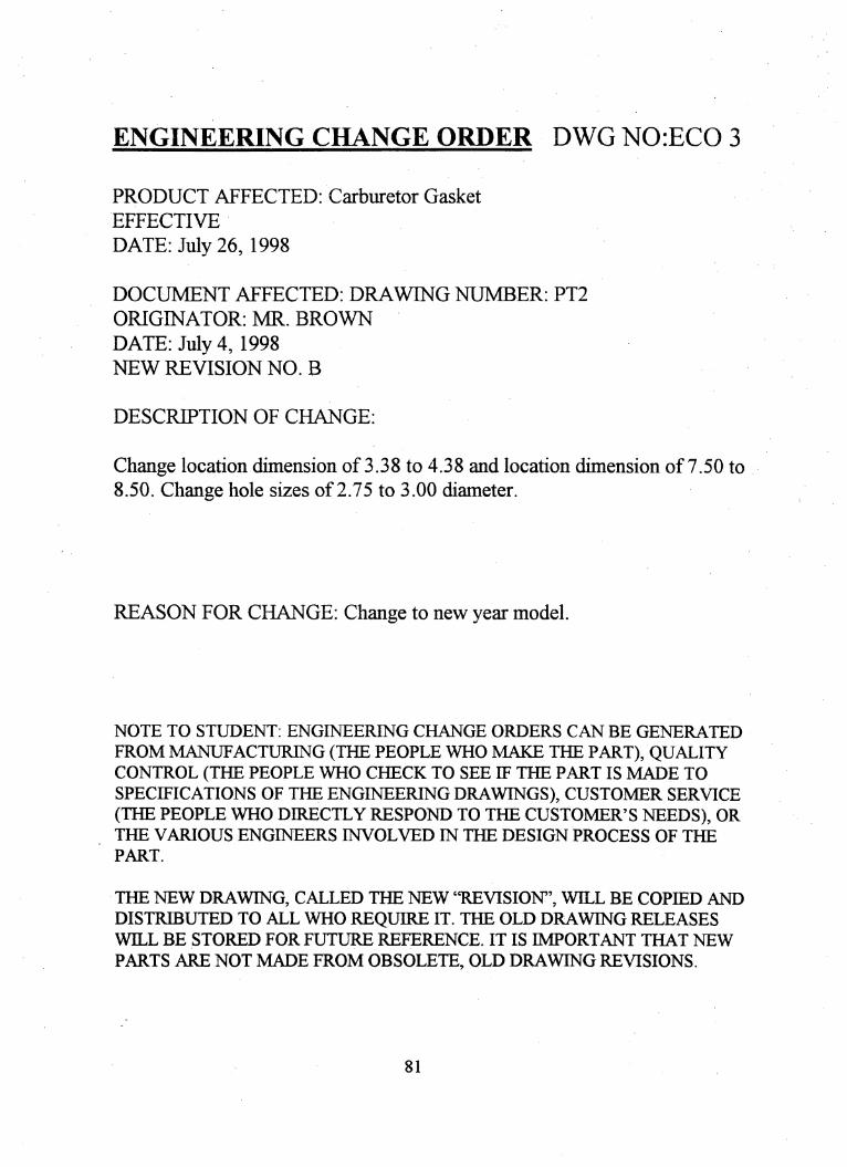
ENGINEERING CHANGE ORDER DWG NOiECO 3
PRODUCT AFFECTED: Carburetor Gasket
EFFECTIVE
DATE: July 26,1998
DOCUMENT AFFECTED: DRAWING NUMBER: PT2
ORIGINATOR: MR. BROWN
DATE: July 4, 1998NEW REVISION NO. B
DESCRIPTION OF CHANGE:
Change location dimension of 3.38 to 4.38 and location dimension of 7.50 to8.50. Change hole sizes of 2.75 to 3.00 diameter.
REASON FOR CHANGE: Change to new year model.
NOTE TO STUDENT: ENGINEERING CHANGE ORDERS CAN BE GENERATED
FROM MANUFACTURING (THE PEOPLE WHO MAKE THE PART), QUALITYCONTROL (THE PEOPLE WHO CHECK TO SEE IF THE PART IS MADE TO
SPECIFICATIONS OF THE ENGINEERING DRAWINGS), CUSTOMER SERVICE(THE PEOPLE WHO DIRECTLY RESPOND TO THE CUSTOMER'S NEEDS), ORTHE VARIOUS ENGINEERS INVOLVED IN THE DESIGN PROCESS OF THE
PART.
THE NEW DRAWING, CALLED THE NEW "REVISION", WILL BE COPIED ANDDISTRIBUTED TO ALL WHO REQUIRE IT. THE OLD DRAWING RELEASESWILL BE STORED FOR FUTURE REFERENCE. IT IS IMPORTANT THAT NEW
PARTS ARE NOT MADE FROM OBSOLETE, OLD DRAWING REVISIONS.
81
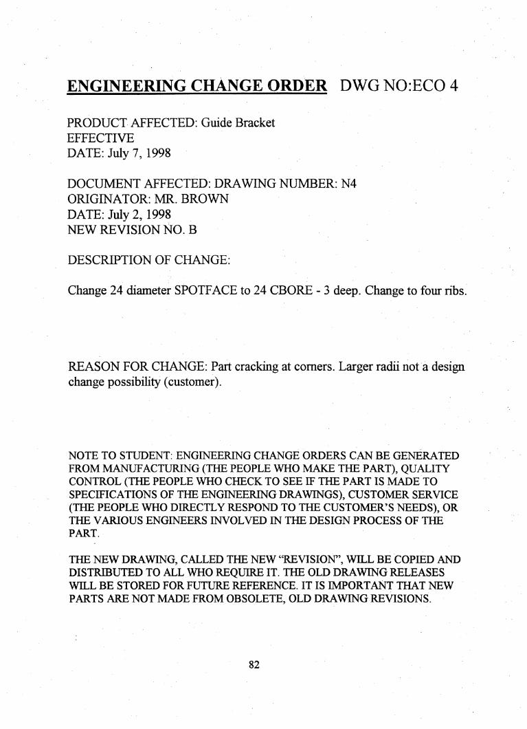
ENGINEERING CHANGE ORDER DWGN0:EC0 4
PRODUCT AFFECTED; Guide Bracket
EFFECTIVE
DATE: July 7, 1998
DOCUMENT AFFECTED: DRAWING NUMBER: N4
ORIGINATOR: MR. BROWN
DATE: July 2,1998NEW REVISION NO. B
DESCRIPTION OF CHANGE:
Change 24 diameter SPOTFACE to 24 CBORE - 3 deep. Change to four ribs.
REASON FOR CHANGE: Part cracking at comers. Larger radii not a designchange possibility (customer).
NOTE TO STUDENT; ENGINEERING CHANGE ORDERS CAN BE GENERATED
FROM MANUFACTURING (THE PEOPLE WHO MAKE THE PART), QUALITYCONTROL (THE PEOPLE WHO CHECK TO SEE IF THE PART IS MADE TO
SPECIFICATIONS OF THE ENGINEERING DRAWINGS), CUSTOMER SERVICE(THE PEOPLE WHO DIRECTLY RESPOND TO THE CUSTOMER'S NEEDS), ORTHE VARIOUS ENGINEERS INVOLVED IN THE DESIGN PROCESS OF THE
PART.
THE NEW DRAWING, CALLED THE NEW "REVISION", WILL BE COPIED ANDDISTRIBUTED TO ALL WHO REQUIRE IT. THE OLD DRAWING RELEASESWILL BE STORED FOR FUTURE REFERENCE. IT IS IMPORTANT THAT NEW
PARTS ARE NOT MADE FROM OBSOLETE, OLD DRAWING REVISIONS
82

CHAPTER TEN
DESIGN ENGINEERING
USING AUTOCAD
83
Chapter Ten
Design Engineering
Using AutoCAD
OBJECTIVES;
Upon completion of this chapter, you will be able to:
• Use AutoCAD as a design tool to solve problems.
• Apply the concept of associative dimensioning.
• Draw interchangeable parts using current drafting-dimensioning
practices.
• Extend your creative attributes in solving engineering problems.
• Effectively communicate your ideas for problem solutions.
84

Container Design Project
Assignment DEI
Design a box to hold 5 "Technical Drawing" textbooks. Packaging material will
be . 12 cardboard. You will create a pattern, complete with allowances for bends and tabs.
You have latitude with tolerance of box, but you must identify the tolerance with a
general note. This is a one-view drawing! Dimensions to .XX. Draw to ANSI standards.
You will have to do a little reading on developments.
85

CAD DRAFTING WORKSTATION
ASSIGNMENT DE2
Your Engineering Design Project is to design a Computer-aided Drafting (CAD)
workstation. What I am looking for is a table that will incorporate a manual elbow type
drafting machine, a CPU, monitor, keyboard, mouse, and printer. I do not want students
to have access to the CPU, but I want to be able to access it easily. (Maybe a key-locked
door or ?). I want the CPU and monitor to be housed so they are difficult to steal, yet get
enough ventilation to work properly. Desktop size should be between 24" X 36" and 36"
X 48". No bigger...no smaller. I want two locking drawers; one to hold drawing supplies
(not paper), and one CD ROMS and diskettes.
Ease of fabrication would be a plus. It must be able to be disassembled to a
reasonable size (for shipping). State what materials and colors you will use.
1. Sketch your idea in isometric or multiview.
2. Keep accurate track of your time (to 15 minute increment s). You will be provided
materials/forms to do this.
3. You may "borrow" parts of other companies designs to integrate into your own,
BUT you may NOT NOT NOT NOT NOT NOT infiinge on someone
else's design! Ask me if you are not sure. This project should represent YOUR
UNIQUE thoughts and ideas!!
4. You will need a Bill of Materials.
86

5. Your finished drawing will be a multiview assembly drawing with basic, overall
dimensions, perhaps sectioned, to show every detail.
6. A "Description Paper" explaining why you designed the table the way you did.
7. Detail drawings of each part, fully dimensioned, will be your last step. After that, a
pictorial drawing can be added.
87
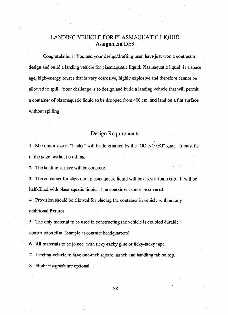
LANDING VEHICLE FOR PLASMAQUATIC LIQUIDAssignment DE3
Congratulations! You and your design/drafting team have just won a contract to
design and build a landing vehicle for plasmaquatic liquid. Plasmaquatic liquid is a space
age, high-energy source that is very corrosive, highly explosive and therefore cannot be
allowed to spill. Your challenge is to design and build a landing vehicle that will permit
a container of plasmaquatic liquid to be dropped from 400 cm. and land on a flat surface
without spilling.
Design Requirements
1. Maximum size of "lander" will be determined by the "GO-NO GO" gage. It must fit
in the gage without crushing.
2. The landing surface will be concrete.
3. The container for classroom plasmaquatic liquid will be a styro-foam cup. It will be
half-filled with plasmaquatic liquid. The container cannot be covered.
4. Provision should be allowed for placing the container in vehicle without any
additional fixtures.
5. The only material to be used in constructing the vehicle is doubled durable
construction film. (Sample at contract headquarters).
6. All materials to be joined with ticky-tacky glue or ticky-tacky tape.
7. Landing vehicle to have one-inch square launch and handling tab on top.
8. Flight insignia's are optional.
88

Evduation;
All entries that pass the drop test without spilling the more than 2 mm of plasmaquatic
liquid will be judged for:
1. Neat appearance.
2. Most innovative design.
3. Accuracy of drawings to finished prototype.
89

BRIDGE DESIGN PROJECT ASSIGNMENT DE4
Congratulations:
You and your design/drafting team have just been awarded a contract to perform
preliminary design activities, to prepare working drawings, and to fabricate and erect a
structure capable of;
Transporting 340 grams of liquid 600 mm across an open span 525 mm. in
distance. The tanker size and shape shall be either a plastic truncated cup with an open
top (size: 48 mm base, 80 mm at the open top, and 88 mm. high with a capacity to hold
340 grams of liquid) or aluminum can (size: 60 mm. diameter, 122 mm. high with the
capacity to hold 340 grams of liquid).
The construction materials for the structure including columns, beams, and/or
girders shall be high strength, durable plastic straws with a size of 196 mm. long and an
outside diameter of 7 mm.
A maximum of 30 straws will be allowed for final construction. The beam
construction methods shall be:
1. Strips of 6 mm wide drafting tape.
2. Strips of 12 mm wide transparent tape.
3. Non-toxic white glue.
4. Model airplane glue.
5. Plastic straw gussets constructed/fabricated with 1,2,3, or 4 above.
90
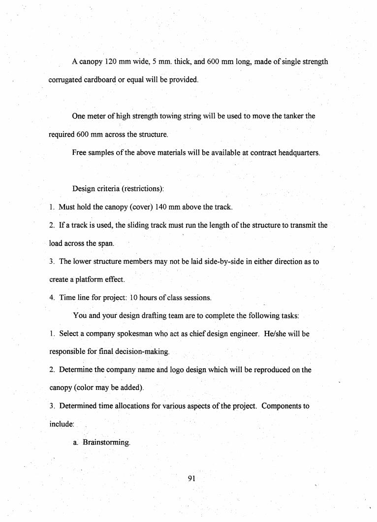
A canopy 120 mm wide, 5 mm. thick, and 600 mm long, made of single strength
corrugated cardboard or equal will be provided.
One meter of high strength towing string will be used to move the tanker the
required 600 mm across the structure.
Free samples of the above materials will be available at contract headquarters.
Design criteria (restrictions):
1. Must hold the canopy (cover) 140 mm above the track.
2. If a track is used, the sliding track must run the length of the structure to transmit the
load across the span.
3. The lower structure members may not be laid side-by-side in either direction as to
create a platform effect.
4. Time line for project: 10 hours of class sessions.
You and your design drafting team are to complete the following tasks:
1. Select a company spokesman who act as chief design engineer. He/she will be
responsible for final decision-making.
2. Determine the company name and logo design which will be reproduced on the
canopy (color may be added).
3. Determined time allocations for various aspects of the project. Components to
include:
a. Brainstorming.
91
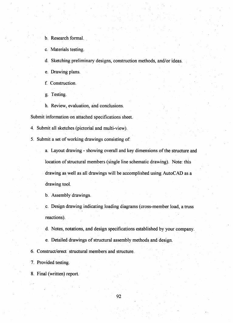
b. Research formal.
c. Materials testing.
d. Sketching preliminary designs, construction methods, and/or ideas.
e. Drawing plans.
f. Construction.
g. Testing.
h. Review, evaluation, and conclusions.
Submit information on attached specifications sheet.
4. Submit all sketches (pictorial and multi-view).
5 . Submit a set of working drawings consisting of;
a. Layout drawing - showing overall and key dimensions of the structure and
location of structural members (single line schematic drawing). Note: this
drawing as well as all drawings will be accomplished using AutoCAD as a
drawing tool.
b. Assembly drawings.
c. Design drawing indicating loading diagrams (cross-member load, a truss
reactions).
d. Notes, notations, and design specifications established by your company.
e. Detailed drawings of structural assembly methods and design.
6. Construct/erect structural members and structure.
7. Provided testing.
8. Final (written) report.
92
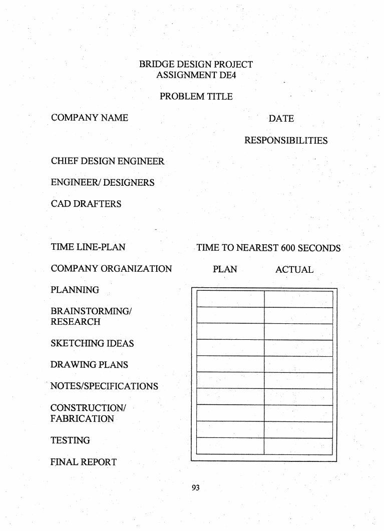
BRIDGE DESIGN PROJECT
ASSIGNMENT DE4
PROBLEM TITLE
COMPANY NAME DATE
CHIEF DESIGN ENGINEER
ENGINEER/ DESIGNERS
CAD DRAFTERS
RESPONSIBILITIES
TIMELINE-PLAN TIME TO NEAREST 600 SECONDS
COMPANY ORGANIZATION PLAN ACTUAL
PLANNING
BRAINSTORMING/
RESEARCH
SKETCHING IDEAS
DRAWING PLANS
NOTES/SPECIFICATIONS
CONSTRUCTION/
FABRICATION
TESTING
FINAL REPORT
93
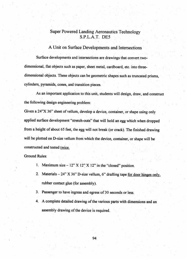
Super Powered Lianding Aeronautics TechnologyS.P.L.A.T. DE5
A Unit on Surface Developments and Intersections
Surface developments and intersections are drawings that convert two-
dimensional, flat objects such as paper, sheet metal, cardboard, etc. into three-
dimensional objects. These objects can be geometric shapes such as truncated prisms,
cylinders, pyramids, cones, and transition pieces.
As an important application to this unit, students will design, draw, and construct
the following design engineering problem:
Given a 24"X 36" sheet of vellum, develop a device, container, or shape using only
applied surface development "stretch-outs" that will hold an egg which when dropped
from a height of about 65 feet, the egg will not break (or crack). The finished drawing
will be plotted on D-size vellum fi-om which the device, container, or shape will be
constructed and tested twice.
GroundRules:
1. Maximum size-12" XI2" XI2" in the "closed" position.
2. Materials - 24" X 36" D-size vellum, 6" drafting tape for door hinges onlv.
rubber contact glue (for assembly).
3. Passenger to have ingress and egress of 30 seconds or less.
4. A complete detailed drawing of the various parts with dimensions and an
assembly drawing of the device is required.
94
5. No crushed paper may be used. All structural items to be drawn and
dimensioned.
6. Time elements; six hours design and layout, color/graphics, and four hours
construction and testing.
Students have the opportunity to try for:
a. Fastest time down.
b. Slowest time down.
c. Closest to target.
d. Furthest from target via: drift or glide
e. Design criteria (functional design). The device, container, or shape will be
released with an underhand thrown motion from a ladder atop of the gym.
f. Each device, container, or shape will be tested a minimum of two flights.
*NOTE: Color and graphics to be added to print prior to construction and testing.
95
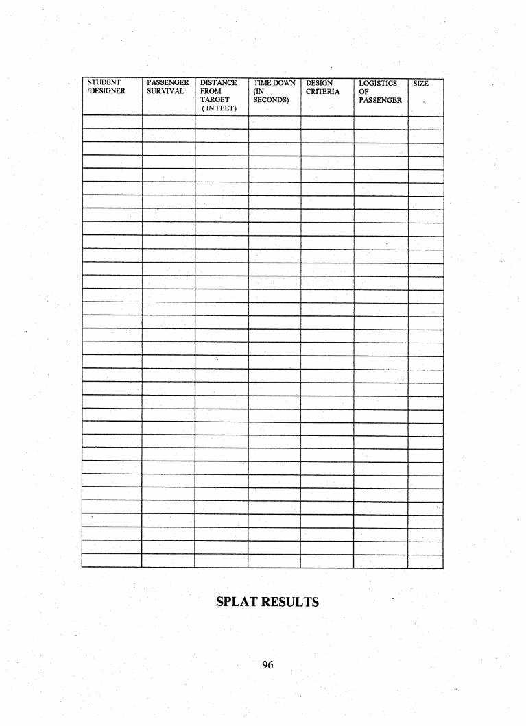
STUDENT
/DESIGNER
PASSENGER
SURVIVAL
DISTANCE
FROM
TARGET
(IN FEET)
TIME DOWN
(INSECONDS)
DESIGN
CRITERIA
LOGISTICS
OF
PASSENGER
SIZE
-
SPLAT RESULTS
96
Free-standing Structure
Assignment DE6
Congratulations! Your design team has been selected to prepare a working model
of a freestanding structure to hold a specific object. The design will involve developing
the tallest structure possible to support the object.
Materials provided:
❖ Three pieces of plain color paper and one piece of plain white paper for experimental
structural development.
❖ One bottle of rubber cement.
Object to be supported:
❖ Ping Pong ball
The design team will involve two members.
Requirements:
❖ No. 1 Develop company name
❖ No. 2 Develop company logo
❖ No. 3 Each design team member is to develop working drawing sketches of the
detailed part and an assembly drawing of the structure. The company name, logo,
and sketches are to be submitted to design headquarters prior to receiving the
materials to construct the structure. Your design team will have 60 minutes to
complete the organizational activities and to experiment with the plain white paper to
determine the best structural members for the structure.
97

❖ No. 4 Construction activities will be limited to 80 minutes.
❖ No. 5 A structure with object in place must be erected in 10 minutes.
❖ No. 6 The structure and object is to be free-standing and is to remain standing for 10
minutes.
Good luck and just as important, good planning, a good design, and goodconstruction!
98
References
Autodesk (1994). AutoCAD release 12 training guide level 1. California:Autodesk.
Cadalyst (March, 1998). Autodesk: Building on 15 years of achievement.Minnesota: Advanstar Communications.
California department of education: Sacramento. (1996). Industrial andtechnology education: career path guide and model curriculum standards.
Erickson, R. (1994). A practical introduction to geometric dimensioning andtolerancing.
Foy, R. (1991). Drafting fundamentals and industrial applications. Minnesota:West.
French, Svenson, Helsel & Urbanick (1990). Mechanical Drawing: CAD-Communications. (11*** Ed.) New York: McGraw Hill.
Garcia & Howe (1992). Learning architectural drafting. New York: Delmar.
Giesecke, F. (1980). Technical drawing, Ed.), New York: Macmillan.
Hepler, D., Wallach, P. (1991). Architecture: drafting and design. (O*** Ed.), NewYork: Glencoe.
Hoffinan, E. (1996). Jig and fixture design. (4*'' Ed.), New York: Delmar.
Jeffries, A., Jones, M. (1994). AutoCad for architecture: covers through release 12.New York: Delmar.
Jeffries, A., Madsen D. (1991). Architectural drafting and design. (2"** Ed.), NewYork: Delmar.
Jeffries, A., Madsen D. (1996). Architectural drafting and design. (3"* Ed.), NewYork: Delmar.
Jensen, C. (1990). Engineering drawing and design. (4*'' Ed.), New York:McGraw-Hill.
Jensen, C., Helsel, J. (1990). Fundamentals of engineering drawing. (3"^ Ed.),New York: McGraw-Hill.
99
Jordan, M. (1993). Engineering drawing problems workbook for autocad release12. New York: Delmar.
Jung, S. (1994). Positional tolerancing training.
Kicklighter, C. (1995). Architecture: residential drawing and design. Illinois:Goodheart-Wilcox. '
Larkin, J. (1996). Practical problems in mathematics for drafting and CAD. (2"^Ed.) New York: Delmar.
Leiblich, J. (1993). Drawing requirements manual. (8*'* Ed.), California: Globalprofessional publications.
Madsen D. (1996). Design dimensioning and tolerancing. Illinois: Goodheart-Wilcox.
Miller, P. (1994). AutoCad for the apparel industry. New York: Delmar.
Olivo, C.T., Olivo, T.P. (1992). Fundamentals of basic technical mathmatics. (6***Ed.), New York: Delmar.
Omura, G. (1993). Mastering autocad: release 12 for windows. California: Sybex.
Ruskin, A. (1996). Drafting by design: design projects and exercises to enhancethe teaching of drafting.
Shumaker, T., Madsen D. (1994). Autocad and its applications: basics rl3 forwindows. Illinois: Goodheart-Wilcox.
Shumaker, T., Madsen D. (1994). Autocad and its applications: rl2 for windows.Illinois: Goodheart-Wilcox.
Spencer, H., Dygdon, J. (1995). Basic technical drawing. (6*** Ed.), New York:Glencoe.
Thomas, T. A. (1991). Technical illustration. (3"* Ed.), Ohio: Glencoe.
Wallach, P. (1989). Drafting in a computer age. New York: Delmar.
Wilson, B. (1992). Design dimensioning and tolerancing. Illinois: Goodheart-Wilcox.
100