Embed Size (px)
Citation preview

California State University, San Bernardino California State University, San Bernardino
CSUSB ScholarWorks CSUSB ScholarWorks
Theses Digitization Project John M. Pfau Library
2002
An effective curriculum for teaching computer numerical control An effective curriculum for teaching computer numerical control
machining machining
Paul Allen Van Hulle
Follow this and additional works at: https://scholarworks.lib.csusb.edu/etd-project
Part of the Vocational Education Commons
Recommended Citation Recommended Citation Van Hulle, Paul Allen, "An effective curriculum for teaching computer numerical control machining" (2002). Theses Digitization Project. 2131. https://scholarworks.lib.csusb.edu/etd-project/2131
This Project is brought to you for free and open access by the John M. Pfau Library at CSUSB ScholarWorks. It has been accepted for inclusion in Theses Digitization Project by an authorized administrator of CSUSB ScholarWorks. For more information, please contact [email protected].

AN EFFECTIVE CURRICULUM FOR TEACHING
COMPUTER NUMERICAL CONTROL MACHINING
A Project
Presented to the
Faculty of
California State University,
San Bernardino
In Partial Fulfillment
of the Requirements for the Degree
Master of Arts
in
Education:
Career and Technical Education
by
Paul Allen Van Hulle
June 2002

AN EFFECTIVE CURRICULUM FOR TEACHING
COMPUTER NUMERICAL CONTROL MACHINING
A Project
Presented to the
Faculty of
California State University,
San Bernardino.
by
Paul Allen Van Hulle
June 2002
Approved by:
S e'cbnd-Re a de r

© 2002 Paul Allen Van Hulle

ABSTRACT
The Access Technology Training Center started out as
a welfare-to-work program funded through a grant from the
Economic Development Agency. In June 2002 the program will
be given to the Mt. San Jacinto College. When the program
is turned over to the College, the center will need to
become self-sufficient by teaching regular for California
State University credit classes to students from the Mt.
San Jacinto College. A curriculum needs to be developed
for teaching students from the college.
The purpose of this project was to develop and
document curricular content for a Computer Numerical
Control education program for Mt. San Jacinto Community
College. The design of the curriculum focuses on showing
students how skills learned in academic classes can be
applied to the workplace.
iii

ACKNOWLEDGMENTS
Wayne Sutter and Family
Mt. San Jacinto College
Economic Development Agency
Michael Conner
Rick Collins
Michael A. De Miranda Ph.D .
Virgil Seaman Ph.D.
Gregory Graham Ph.D.
Don Maurizio Ph.D.
Joseph Scarcella Ph.D.
Ron Pendleton Ph.D.
Timothy Thelander
Society of Manufacturing Engineers
iv

DEDICATION
To my parents and family, for their guidance and
support. Without these things this thesis and my entire
education would not have been possible.

TABLE OF CONTENTS
ABSTRACT..................................................... iii
ACKNOWLEDGMENTS ............................................. iv
LIST OF TABLES.............................................. vii
LIST OF FIGURES..............................................viii
CHAPTER ONE: BACKGROUND
Introduction.................................. 1
Context of the Problem................................ 1
Purpose of the Project........ •..................... 2
Significance of the Project ......................... 2
Assumptions ........................................... 3
Limitations and Delimitations ........... < ......... 3
Limitations ..................................... 4
Delimitation's................................... 4
Definition of Terms .................................. 4
Organization of the Thesis ......................... 9
CHAPTER TWO: REVIEW OF THE LITERATURE
Introduction .......................................... 10
History of Computer Numerical Control ............ 10
The Computer.................................... 11
Societal Impact of Computer AidedMachining........................................ 14
Occupational Outlook........ 15
Skills Defined ........................................ 21
Contextual Learning .................................. 24
v
Occupational Standards for Computer Numerical Control Education ..................................... 27
Summary................................................ 31
CHAPTER THREE: METHODOLOGY
Introduction..................................... 33
Population Served .................................... 33
Handbook Development ................................. 33
Handbook Resources and ContentValidation....................................... 33
Handbook Design ................................. 34
Summary................................................ 35
CHAPTER FOUR: BUDGETARY CONSIDERATIONS
Introduction .......................................... 36
Summary . .................................. 38
CHAPTER FIVE: CONCLUSIONS AND RECOMMENDATIONS
Introduction .......................................... 39
Conclusions........................................... 39
Recommendations ....................................... 40
Summary................................ 41
APPENDIX: COMPUTER AIDED MACHINING...........;......... 42
REFERENCES.................................. 150
vi

LIST OF TABLES
Table 1. Computer Numerical Control CareerOpportunities ..................................... 17
Table 2. Employment Trends................................. 19
Table 3. Employee Supply and Demand Data.............. . 20
Table 4. Directory of California Wages forComputer Numerical Control ...................... 21
Table 5. Directory of California Wages forMachinists......................................... 22
Table 6. Computer Aided Manufacturing and Advanced Computer Numerical Control Technical Workplace Competencies ........................... 28
Table 7. Secretary's Commission on AchievingNecessary Skills Course Competencies .......... 30
vii

LIST OF FIGURES
Figure 1 Industries' need for Skilled, Unskilled, and Professional Workers for Years 1950, 1991, and 2000 ............................. 23
viii

CHAPTER ONE
BACKGROUND
Introduction
The contents of Chapter One presents contents of an
overview of the project. The contexts of the problem are
discussed followed by the purpose, significance of the
project, and assumptions. Next, the limitations and
delimitations that apply to the project are reviewed.
Finally, definitions of terms are presented.
Context of the Problem
There is a significant need for educational
curriculum that will help students not planning on
attending college gain skills that will sustain them for
life. Preparing students to contribute to society
throughout their lives and giving them skills needed for
entry into the workforce are crucial to our economy.
Interest in establishing industry-driven skill standards
is growing. If the United States is to remain competitive'
internationally states must increase the skills and
productivity of the front-line workforce (Illinois
Occupational Skill Standards, 1997).
The manufacturing industry has experienced major
technological changes. Today's production workers need to
1

be trained in higher level skills. "Employers need workers
with a knowledge of robotics, computers, Computer
Numerically Controlled (CNC) machines, and Computer Aided
Drafting [CAD]" (Skilled Occupations, 1994, p. 1) .
Examples of some skills required of employees related to
the Computer Aided Machining field would be the ability to
follow written instructions, interpersonal skills,
computer skills, metalworking skills, manual dexterity,
mathematical skills, and spatial skills (Skilled
Occupations, 1994, p. 1).
Purpose of the Project
The purpose of this project was to develop and
document curricular content for a Computer Numerical
Control education program at Mt. San Jacinto Community
College. The design of the curriculum focuses on showing
students how skills learned in academic classes can be
applied to the workplace.
Significance of the Project
Computer Aided Machining (CAM) is an occupation that
requires workers that are highly competent both in
academic courses such as math, English, and career and
technical education courses. Advancement in the field of
Computer Aided Machining requires that workers understand
2
how skills and theories learned in academic classes are
transferable to the workplace. "Most firms usually accept
training as a substitute for work experience" (San Diego
County 2001 occupational outlook report, 2001, p. 92) .
Assumptions
The following assumptions were made regarding the
proj ect:
1. It was assumed, instructors using the curriculum
would have an understanding of how to do hand or
manual programming and how to use Mastercam.
2. It was also assumed the students were taught
basic operation of the computer and file
management techniques using the Windows
environment, measurement, blueprint reading or
drafting, and basic shop safety before starting
this curriculum.
Limitations and Delimitations
During the development of the project, a number of
limitations and delimitations were noted. These
limitations and delimitations are presented in the next
section.
3

Limitations
The following limitations apply to the project:
1. The curriculum section of the project was
designed for use with Mastercam Computer Aided
Machining Software Version 8.
2. The project was limited to Mt. San Jacinto
Community College's Access Technology Training
Center.
Delimitations
The following delimitations apply to the project:
1. The curriculum may be altered for use in a high
school or technical education program.
2. The documentation and curriculum development
section of the project could assist other
teachers of manufacturing or machining education
to develop their own Computer Aided Machining
education program.
Definition of Terms
The following terms are defined as they apply to the
proj ect.
Absolute Measuring Systems - A method of defining the
coordinate locations of point to which the cutter (or
4

workpiece) is to move based on the fixed machine
point (Oberg, 2000).
Applied or Contextual Learning - A learning strategy
emphasizing the context within which a student might
apply the skills or knowledge derived from the
instruction. It addresses multiple learning styles
among students and is based in learning theory
indicating the impact learning-by-doing (Hutcheson,
1999) .
Cartesian Coordinate System - A coordinate system that
consists of three axes'(X, Y, and Z) that are
perpendicular to each other. A grid is formed
consisting of numerical graduations, representing the
distances from the intersection of the three axes
called origin (Evans, 2001).
Circular Interpolation - A mode that reduces the number of
calculations required on a numerical control machine
to program a curved surface. The circular
interpolator in the machine control unit will
automatically compute the necessary number of
intermediate points to describe the circular cut. It
also generates the electronic signals that will run
the servos and guide the cutting tool in making the
cut (Walker, 2000).
5

Computer Aided Drafting and Design (CADD) - A
computer-based system used to create, modify, and
communicate a plan or product design (Wright, 1996).
Computer Aided Machining (CAM) - A broad term used to
define the use of the computer in many manufacturing
activities such as factory simulation, planning
analyses and part programming (Oberg, 2000) .
Computer Aided Programming - Using CAD/CAM software
systems to generate part programs (Lin, 1998) .
Computer Numerical Control (CNC) - The numerical control
system in which a dedicated, stored computer program
is built into the control to perform basic and
advanced NC functions (Lin, 1998).
Datum - A reference point or plane from which movement or
measurements are made (Krar, 2001) .
G-Code, The Code, or Code - Preparatory functions (G-Code)
are programmed with an address G, typically followed
by two digits, to establish the mode of operation in
which the tool moves (Evans, 2001) .
Hand or Manual Programming A part program is prepared by
manually inputting the coded instructions into the
controller (Lin, 1998).
Incremental Measuring Systems - A method of identifying
the coordinates of a particular location in terms of
6

the distance of the new location from the current
location (Oberg, 2000).
Mastercam - Computer Aided Machining software program used
in schools and industry (Lin, 1998).
Miscellaneous Control Signals - A set of on/off signals to
implement the control of the speed and direction of
the spindle rotation, control of coolant supply,
selection of cutting tool, automatic clamping and
unclamping, etc. (Lin, 1998).
Motion Control Signals - A series of electric pulse trains
that are used to control the position and the speed
of the machine table and spindle (Lin, 1998).
Numerical Control (NC) - A system of control that uses
numerically coded instructions to operate motors and
other devices that run a machine (Repp, 1984).
Origin - A starting point for the coordinate system used
to machine parts; a fixed point on a blueprint from
which dimensions are taken (Evans, 2001).
Polar Coordinate System - Points are defined by their
linear distance’ as measured parallel to the
fundamental axis from the origin. In polar
coordinates, points are defined by their rotational
angular position from the reference axis and by the
radial distance from the origin (Kibbe, 2002).
7
Punch Tape - A rarely-used storage medium made of paper,
plastic, and polyester laminates, that is used for
the permanent storage and loading of CNC part
programs, and on which characters are represented by
combination of holes (Krar, 2001) .
Single step or block - The execution of a single block of
information in the program is initiated by activating
a switch or button on the control panel. While in
this mode, each time to cycle start button is
pressed, only one block of information will be
executed (Evans, 2001).
Technical Education - A term used to identify a level or
sub-set of vocational or occupational education that
involves the preparation for or upgrading within
occupations that lie some place between the skilled
craftsman and the professional. The occupations tend
to involve a heavier reliance upon understanding and
competence in mathematics and science than might be
found in most occupations that require less than
baccalaureate level preparation (as cited in
Scarcella, 2001).

Organization of the Thesis
The thesis portion of the project was divided into
five chapters. Chapter One provides an introduction to the
context of the problem, purpose of the project,
significance of the project, limitations and
delimitations, and definitions of terms. Chapter Two
consists of a review of,relevant literature. Chapter Three
documents the steps used in developing the project.
Chapter Four has the budgetary considerations. Chapter
Five presents conclusions and recommendations drawn from
the development of the project. Project references follow
Chapter Five. Finally, the Appendix consists of the
project: consists of Coordinate Systems for Computer Aided
Machining and Manual Programming; Mastercam Computer Aided
Machining Program; Computer Numerical Control Machine
Programming Using Manual Methods.
9

CHAPTER TWO
REVIEW OF THE LITERATURE
Introduction
Chapter Two consists of a discussion of the relevant
literature. Specifically, history of Computer Numerical
Control, occupational outlook, skills defined, Computer
Aided Manufacturing and advanced Computer Numerical
Control technical workplace competencies, and The
Secretary's Commission on Achieving Necessary Skills
Course Competencies.
History of Computer Numerical Control
Numerical Controlled machines had been associated
with manufacturing industry for many years. In the past,
numerically controlled machines were controlled using
punch tape. Punch tape type numerically controlled
machines of the past worked on similar principles as the
old fashioned player piano (Curran, 2001; Krar, 2001) . The
player piano of the past blew air through holes punched in
a role of paper to control which notes were played. Other
examples of machines that used punch tape control were the
early weaving machines of the 1800s. "Weaving machines
used metal cards with holes punched in them to control the
pattern of the cloth being produced" (Curran, 2001, p. 2) .
10

The Numerically Controlled milling and turning machines of
the past were controlled by punch tape. The holes in the
punch tape would activate switches that sent signals to
accurate stepper motors telling them how much to move at
the desired feed rate. Many of these early NC machines
were non-simultaneous. In other words, only one motor on
the machine could be moved at a time. This made it
impossible to make complex three-dimensional shapes (Krar,
2001).
The Computer
The development of the computer was a critical
turning point for the introduction of CNC. On February 15,
1946 at 7:00 P.M. Eastern Time a press release about the
first computer was published. The press release stated: "A
new machine that is expected to revolutionize the
mathematics of engineering and change many of our
industrial design methods was announced today by the War
Department" (War Department, 1946, p. 1). The machine was
named the ENIAC, which stood for "Electronic Numerical
Integrator and Computer" (War Department, 1946, p. 1). The
ENIAC took up 1800 square feet of floor space and weighed
30 tons (Stern, 1995) . The war department press release
further stated:
11

The ENIAC is capable of computing 1000 times faster than the most advanced general-purpose calculating machine previously built. The electronic methods of computing used in the ENIAC make it possible to solve in hours problems which would take years on a mechanical machine—a time so long as to make such work impractical. (War department, 1946, p. 1)
It can be inferred from the press release that
society of the 1940s was concerned that computers would
replace human thinking.
The new machine does not remove the need for legitimate experimentation, whose purpose it is to discover fundamental principles and factors which affect those principles. Likewise, it was pointed out that the electronic calculator does not replace original human thinking, but rather frees scientific thought from the drudgery of lengthy calculating work. (War Department, 1946, p. 1)
In 1947, the need for more advanced numerically
controlled machines and computer numerically controlled
machines was created by the United States Air Force's need
for complex shaped aircraft parts such as missile
components and helicopter rotor blades. These aircraft
components needed to have high precision and uniformity
and be created quickly with demanding production schedules
that were very hard to meet using manual machining
methods. The_Massachusetts Institute of Technology (MIT),
was contracted by the Airforce to develop Numerical
Control and in turn speed up production (Krar, 2001). The
12

press release about the ENIAC also showed an interest in
using the computer for aerodynamics. It stated: "Although
the machine was originally developed to compute lengthy
and complicated firing and bombing tables for vital
ordnance equipment, it will solve equally complex
peacetime problems such as nuclear physics, aerodynamics
and scientific weather prediction" (War Department, 1946,
p. 1) .
In 1952, the Massachusetts Institute of' Technology
demonstrated a Computer Numerically Controlled machine,
which made parts through simultaneous three-axis cutting
tool movements (Krar, 2001) . Integrated circuits,
introduced in 1959, helped decrease the size of the CNC
machine. An integrated circuit is a tiny electronic
circuit used to perform a specific electronic function.
Research from 1999 (Encarta) suggested that an integrated
circuit measuring the size of a fingernail can contain as
many as 5,000 circuit elements.
During recent years, the functional capability of ICs has steadily increased, and the cost of the functions they perform has steadily decreased. This has produced revolutionary changes in electronic equipment—vastly increasing functional capability and reliability combined with great reductions in size, physical complexity, and power consumption. (Encarta, 2000, Integrated Circuits)
13

Since CNC machines use similar circuitry as a personal
computer the CNC machine benefited from the development of
the integrated circuit. The integrated circuit improved
the functionality, accuracy and size if the CNC machine
(Curran, 2001) .
The first Computer Numerical Control machines with
greater capability than Numerical Control machines were
produced in 1976. The major difference between Numerical
Control machines and Computer Numerical Control is
Numerical Control machines could only read one single step
or block at a time and execute it. However, Computer
Numerical Control machines could store whole programs. CNC
provides greater speed and versatility for making changes
to the program (Curran, 2001; Repp, 1984).
Societal Impact of Computer Aided Machining
The history of the societal impact of computers and
computer aided machining systems has important
implications for the occupational outlook for students
considering a career in computer aided machining. As
mentioned previously when the ENIAC was introduced society
was very concerned that machines would replace human
workers. According to Volti (1992) when people think of
technological change they often think they will lose their
jobs to legions of robots performing work 24 hours per day
14

without assistance of humans. CAM has exasperated this
false assumption. When the product design is completed CAM
can be used to run CNC machines to produce the part. There
are many problems with the theory that the machine can do
all this without the assistance of humans. Humans are
still essential for programming the design of. the part,
machine setup, transporting the part from one operation to
the next, and monitoring and adjusting the machine for
cutter tool wear.
Current trends show that the manufacturing industry
will never become as automated as not to need humans to
intervene when problems arise. Workers will need to
constantly improve their skills to keep up with advancing
technology. The future looks bleak for the mature workers
who have not updated their skills (Volti, 1992) . Volti
suggests this is when well-planned vocational education
programs can help retrain under skilled workers.
Occupational Outlook
Computer Numerical Control operators play a major
role in producing most of the consumer products, which
people rely upon daily (Numerical Control Machine
Operators, 1998, p. 1). Even the plastic parts of a cell
15

phone were molded using a mold that was created on a
numerically controlled machine.
The operations of the manufacturing environment can
be categorized as NC shop management, NC part programming,
tool and fixture design, machine maintenance, and NC
machine operations. The following diagram shows some of
the job responsibilities in each of these categories. Many
of these job responsibilities require people that are
skilled in both academics and technical education and to
have college or vocational education. Table 1 details the
job responsibilities and educational experience of a
Computer Numerical Machine operator and programmer.
According to the occupational outlook handbook the
outlook for careers in manufacturing was predicted to be
excellent; however, to be successful workers must be
highly skilled and well trained. Employers report
difficulties in finding workers with the skills and
knowledge necessary to fill machining and CNC programming
openings. Referring to table 2 on the following pages
Riverside, and San Bernardino employers find difficulty
finding qualified or skilled CNC tool operators and
machinists. The occupational outlook handbook reported
16

Table 1. Computer Numerical Control Career Opportunities
JobTitle
Responsibility Required Job Skills
Education/Experience
NC Oversee NC Management 4-yearmanager operations. Skills. collegeor NC personnel Machining degree withsupervisor hiring, training Knowledge. several
and j ob NC programming years ofassignment. and Operation manufacturi
Coordination with otherdepartments.
Evaluate andacquire new CNC machine tools and CAD/CAM software.
background. ngexperience.
Process Determine what Overall At leastplanner machining knowledge of 2-year
processes to be machining, collegeused with what tooling, and degree,sequence and in capability of 4-yearwhat machines. available college
Select cutting equipment. degreetools and work holding devices and fixtures.
Prepare operation sheets and tooling sheets.
Good background inmanufacturing and CNC.
preferred.
Part Prepare part Good command at 2-yearprogrammer programs. math, geometry college
Prepare NC and degree ordocuments trigonometry. vocationalconcerning setup Sound knowledge technicalinstructions. of machining. school.
Prepare process plan if needed.
Blueprint reading.
Computer skills. Use of CAD/CAM software.
Tool Select standard Good command at At least 2-designer tooling. locating and year college
Design special- clamping degree withpurpose tooling. knowledge.
Knowledge oftool making.
Understanding of
tool and machine experience, 4-year
standard tooling and fixturing.
college degree preferred.
17

JobTitle
Responsibility Required Job Skills
Education/Experience
Toolmaker
Assemble and preset standard tooling.
Make special- purpose tooling.
Repair damaged tooling items.
Highly skilled in machining.
Knowledge inCNC.
Print reading and making.
4-yearapprenticeshipprogram.
Machinesetupperson
Set up fixture and cutting tools on the machine.
Coordinate the machine.Determine and enter offset and compensation values.
Correct errors in tooling and program.
Run the program.
Good knowledge in machining and tooling.
Understanding of part program and machine functions.
MachinistexperiencewithextensiveCNCknowledge.
Machineoperator
Load and Unload work pieces.
Monitor machining in progress.
SPC charting. Regular check-up.
General knowledge of machining.
Technical programs in vocational technical school,areaoccupational school, community college.
(Lin, 1998, p. 1-5) .
slower growth for CNC programmers as compared to
machinists "primarily because the machinist occupation is
larger" (Occupational Outlook Handbook, 2001) . Employment
trends also show (as shown in table 3) Riverside, San
Bernardino, and Orange Counties expect either growth or
stability as opposed to decline in this occupational
field.
18

Table 2. Employment Trends
Employment Development Department Employment Trends
Occupation Title: Numerical Control, Machine-Tool Operators and Tenders (CNC) or Machinists (Machinists) as listed
Employment Levels During the Past Year
Employment Levels Projected Over the Next
two yearsDecline Remain
StableGrow Decline Remain
StableGrow
OrangeCNC, 99 7% 47% 47% • ■ 13% 40% 47%
Riverside Machinists, 98 7% 53% 40% 7% 47% 46%
RiversideCNC, 98 13% 53% 34% 7% 40% 53%
San Bernardino Machinists, 99 6% 56% 38% 6% 75% 19%
Orange County data from: {Orange County 2000 occupational outlook, 2000, p. 104)Riverside County data from: {Labor market information study, 1999, p. 34 & 42)San Bernardino County data from: {County of SanBernardino, 2000, p. 34)
Most employers will substitute two years of training
for experience in the field (San Diego County 2001
occupational outlook report, 2001, p. 92). Students that
complete the Access Technology Training Center courses
offered through the Mt. San Jacinto Community College would
likely fall in the category of experienced but new to the
firm. Referring to tables 4 and 5 the pay range for people
with experience but new to the firm had a median of $9.SO-
12. 80 per hour for CNC operators and a median of $12.00-14.00
19

per hour for machinists. Considering California's minimum
wage as of January 1, 2002 was $6.75 the wages for CNC
operators and Machinists are significantly higher than
minimum wage (Minimum wage laws, 2 001) .
Table 3. Employee Supply and Demand Data
Supply and Demand DataCounty's Employers ability to find Experienced or Inexperienced Employees Occupation Title: Numerical Control, Machine-Tool Operators and Tenders
(CNC) or Machinists (Machinists) as listed
Experienced/Qualified InexperiencedVery
DifficultModerately or Scmewha Difficult
NotDifficult
VeryDifficult
Moderately or Sarewba Difficult
NotDifficult
Los Angeles CNC, 99 X X
Los Angeles Machinists, 98 X X
OrangeCNC, 99 X X
Riverside Machinists, 98 ■ X X
RiversideCNC, 98 X X
San Bernardino Machinists, 99 X X
San Diego Machinists, 98 X X
Los Angeles County Machinists data from: (Occupational outlook Los Angeles - a labor market information study,1998, p. 58)Los Angeles County CNC data from: (Occupational outlook Los Angeles County - a labor market information study,1999, p. 72)Riverside County data from: (Labor market information study, 1999, p. 34 & 42)San Bernardino County data from: (County of San Bernardino - 1999 occupational outlook report, 1999, p. 33)San Diego County data from: (San Diego 2001 Occupational outlook report, 2001, p.93)
20

Skills Defined
Research shows that industries' need for skilled
workers have increased. If a person does not have skills
to offer companies, they will have difficulty gaining
employment working above minimum wage. As shown in the
following three figures, "since the 1950's there has been
a dramatic increase in the need for skilled workers"
(McAlonan, 1999, p. 24).
Table 4. Directory of California Wages for Computer
Numerical Control
Employment Development Department 2000 Directory of California Local Area Wages
Occupation Title: Numerical Control Machine Tool Operators & Tenders-Metal & Plastic
Ehtry levelNo Experience
ExperiencedNew to Elrm
Experienced3 Years with Elrm
low High Mfedian lew High Median Lew High MedianIds Angeles Gcsunty Non Union, 99 6.50 13.35 7.75 7.00 20.00 12.00 10.60 25.00 16.15
los Angeles County Union, 99 13.00 13.00 13.00 11.50 15.32 12.80 12.90 19.00 17.34
Orange County,99 7.50 14.00 9.23 6.14 18.00 10.00 10.50 22.60 15.00
Riverside,98 5.75 7.00 6.25 6.25 20.00 9.50 . 9.00 25.00 15.00
All figures are in dollars/hourSan Diego, and San Bernardino had no data
(California employment development department - Labor market information, Numerical-Control machine-tool operators & tenders-Metal & plastic, 2000, p. 1)
21

Table 5. Directory of California Wages for Machinists
Employment Development Department 2000 Directory of California Local Area Wages
Occupation Title: Machinists
Entry levelNo Experience
ExperiencedNew to Firm
Experienced3 Years with Firm
low High Median low High Median lew High MedianLos Angeles Ctounty 98 5.75 16.20 9.00 7.19 25.59 14.00 9.59 29.83 18.00
Orange County,99 5.75 16.20 9.00 7.19 25.57 14.00 9.59 29.83 18.00
Biversicfe,98 5.50 15.00 7.50 10.00 20.00 15.00 11.00 25.00 18.00
San Bernardino,99 N/A N/A N/A 9.00 17.70 12.00 11.00 19.18 14.50
San Diego, Ncn-Union, 98 5.75 12.00 7.00 6.75 15.00 12.00 8,00 19.00 16.00
San Diego,Union, 98 10.00 10.25 10.13 11.00 16.00 13.50 15.00 22.00 18.50
All figures are in dollars/hour
San Diego, Riverside, San Bernardino, and Los Angeles data from (California employment development department - Labor market information, Machinists, 2000, p. 1)Orange Co. data from: (Orange County 2000 occupational outlook, 2000, p. 104)
22

Figure 1. Industries' need for Skilled, Unskilled, and
Professional Workers for Years 1950, 1991, and 2000
(McAlon, 1999, p. 24)
23

Skills are the things that a person knows that can be
transferred from one field to another (Bolles, 1994,
p. 174). Examples of skills would be the ability to
synthesize and interpret data, manage people, and perform
part or machine setup. According to Dr. Zargari from
Morehead State University technological advancements and
competition abroad have a significant impact on the work
place. Qualification requirements are always changing.
"The danger for the present and future is not lack of
jobs, but lack of technological skills" (Zargari, 1997,
p. 5). People are in danger of having a critical shortage
of workers with the education and training necessary to
handle the jobs that need to be filled (Zargari, 1997) .
Students must be taught how to work with technology
to perform skills. The nature of the work force changed
dramatically. Workers are required to be skill adaptive.
Low-skill jobs are gradually being replaced by jobs
requiring, mathematics, language, technological literacy,
and problem-solving skills (Zargari, 1997).
Contextual Learning
Research in reform of education called into question
the organization and operation of traditional education
systems. This research challenges the validity of the
24

notion basic skills taught using traditional instruction
methods can be applied in context in the real world.
Traditional instruction assumes that:
" (a) competencies can be decomposed intoconstituent parts, or subskills, that can be learned and then put back together and the competency will be acquired,
(b) individual skills can be taught out ofcontext on the assumption that they can then be applied appropriately in context. (Milne, 1998, p. 68)
The research into whether or not traditional
instruction is showing students how subjects taught in the
traditional classroom applies to the real world has
resulted in the theory of contextual learning. The process
of contextual learning helps students understand how
subject matter content relates to real world situations.
This process "motivates students to make connections
between knowledge and its application to their lives as
family members, citizens, and workers" (Blanchard, 2000a).
Blanchard defines contextual instruction that:
• Relies on spatial memory,• Typically integrates multiple subjects,• Value of information is based on individual
need,• Relates information with prior knowledge,• Authentic assessment through practical
application of solving of realistic problem. (Blanchard, 2000a, p. 2)
25

As compared to contextual instruction, traditional
instruction is instruction which:
• Relies on rote memory,• Focuses on a single subject,• Value is determined by the instructor,• Fills student with deposits of information
until needed,• Assessment of learning is only for formal
academic occasions such as exams.(Blanchard, 2000a, p. 2)
As can be seen from the previous section on skills
that employers require of employees in the field of
Computer Numerical Control operation and programming,
Employers require employees that can access information in
technical manuals and that can communicate with others to
solve problems. According to Milne (1998) "Schools place a
large emphasis on the demonstration of student performance
without the assistance of resources, such as books,
calculators, and other people. These resources are
routinely utilized in out of school settings" (p. 72). One
of the emphases of contextual based education is students'
should be encouraged to practice accessing information to
solve real world problems.
The methods proscribed by the research on contextual
instruction delivery (Blanchard, 2000a; Milne, 1998)
involve fewer lectures and more hands on activities. Much
26

of the curriculum presented in the project section is
based on contextual learning.
Occupational Standards for Computer Numerical Control Education
San Diego City College's Center for Applied
Competitive Technologies (CACT) surveyed eight Southern
California companies to determine what technical workplace
competencies they consider important for training of
Computer Numerical Control Programmers/Operators. The
competencies researched by San Diego City College focused
on training of both Electro-discharge machine operators
and CNC operators. The project of this thesis- focused on
CNC operators and machinists. As shown below the research
gives a broad spectrum of the skills required of employees
in the field of CNC operation and programming.
Other competencies that should be considered are the
skill competencies developed by the secretary's commission
on Achieving Necessary Skills (SCANS). The SCANS
competencies detailed in table 8 represent the results of
U.S. Department of Labor's meetings with public employers,
unions, business owners, and workers and supervisors in
shops, plants, and stores. The purpose of these meetings
was to identify the competencies and skills businesses
require of employees. According to the SCANS report
27

students should develop these competencies if they are to
enjoy a productive and satisfying life (What work requires
of schools, 1991, p. 10).
Table 6. Computer Aided Manufacturing and Advanced
Computer Numerical Control Technical Workplace
Competencies
CAM and CNC Technician . . . program, edit, setup, andoperate CNC lathes, mills and grinders to perform machining operations necessary to produce work pieces to reference engineering standards .
A. Practice1. 2 . 3.4 .5 . 6. 7 .
SafetyUse proper safety equipmentIdentify proper clothingState proper attitudes for safetyHandle chemicals properlyIdentify fire hazards in machiningDemonstrate proper personal hygieneDemonstrate proper laboratory cleaning
B. Perform Measurements1. Identify applications and limitations of
measuring instruments2 . Demonstrate use of measuring instruments
C. Apply Mathematical Concepts1. Perform mathematical computations with
calculator2. Calculate fractions and decimals with
calculator3. Convert Metric and US standard units of
measure4. Perform RPM calculations5. Perform feed rate calculations6. Perform depth of cut calculations7. Perform thread cutting calculations8 . Perform tap drill calculations9. Interpret reference tables related to
machining10. Apply Cartesian coordinate system to
machining11. Perform trigonometric calculations12 . Perform Pythagorean Theorem calculations 13. Perform polar trigonometric calculations
28

D. Read Blueprints123
4
Describe types of blueprint drawingsDescribe blueprint dimensionsInterpret title, notes, revision and material informationInterpret blueprint drawings
E. Program CNC machines and EDM1 Demonstrate cutting tool identification and
application2 Identify and describe machine operation
nomenclature3 Identify and describe essentials of CNC
systems4 Identify and describe types of CNC hardware
and software5 Identify and describe machine axes and
coordinate systems6. Describe and interpret CNC coding systems7 Write NC programs8 Plan process for NC operations9 Demonstrate use of electronic discharge
machine (EDM)F. Operate CNC machines & EDM
1 Describe vertical machining process and safety
2 Describe vertical machining functions3 Set-up and program operation of vertical
machine4 Demonstrate machining of objects on vertical
machining center5 Perform CNC turning process, equipment and
safety6 Perform advanced EDM operations7 Describe turning center8 Set-up and program operation of turning
center9 Demonstrate machining of objects on turning
centerG. Use Computers
1 Demonstrate use of computer hardware2 Select/use computer operating system3 Demonstrate use of basic DOS commands4 Demonstrate use of Windows and Windows NT
commands5 Demonstrate use of MACROS in Windows and
Windows NT programs6 Demonstrate use of computer communication
systems
29

H. Use CNC Verification Programs12
3
Identify CNC verification software programs Program and create CNC verification using program iconsProgram CNC verification using pull-down menus
I. Using CAD/CAM Programs1 Demonstrate understanding of CAD/CAM programs2 Access CAD program options3 Create designs with CAD section of CAD/CAM
program4 Demonstrate ability to use program functions5 Process tool path data
(Machine tool advanced skills, 1996, p. 21-22)
Table 7. Secretary's Commission on Achieving Necessary
Skills Course Competencies
Five Competencies:_________________________________Resources: Identifies, organizes, plans, and allocates resources
A. Time - Selects goals-relevant activities, ranks them allocates time, and prepares and follows schedules.
B. Money - Uses or prepares budgets, makes forecasts, keeps records, and makes adjustments to meet objectives.
C. Material and Facilities - Acquires, stores, allocates, and uses materials or space efficiently.
D. Human Resources - Assesses skills and distributes work accordingly, evaluates performance and provides feedback.
Interpersonal: Works with othersA. Participates as a Member of a Team - contributes to
group effort.B. Teaches Others New Skills.C. Serves Clients/Customers - works to satisfy
customers' expectations.D. Exercises Leadership - Communicates ideas to justify
position, persuades and convinces others, responsibly challenges existing procedures and policies.
E. Negotiates - works toward agreements involving exchange of resources, resolves divergent interests.
F. Work with Diversity - works well with men and women from diverse backgrounds.
30

Five Competencies:_________________________________Information: Acquires and uses information
A. Acquires and Evaluates InformationB. Organizes and Maintains InformationC. Interprets and Communicates InformationD. Uses Computers to Process Information
Systems: Understands complex inter-relationshipsA. .Understands Systems - knows how social,
organizational, and technological systems work and operates effectively with them.
B. Monitors and Corrects Performance - distinguishes trends, predicts impacts on system operations, diagnoses deviations in systems' performance and corrects malfunctions.
C. Improves or Designs Systems - suggests modifications to existing systems and develops new or alternative systems to improve performance.
Technology: Works with a variety of technologiesA. Selects Technology - chooses procedures, tools or
equipment including computers and related technologies.
B. Applies Technology to Task - understands overall intent and proper procedures for setup and operation of equipment.
C. Maintains and Troubleshoots Equipment - prevents, identifies, or solves problems with equipment, including computers and other technologies.
(What work requires of schools, 1991, p. 12)
Summary
Many books and articles on the subject of Computer
Numerical Control Programming and the history of computers
have been written. Chapter Two presented the history of
numerical control, including the social implications of
automation and computers. A brief section was offered
about the skills required and the occupational outlook for
CNC programmers and operators. The definition of
31

contextual learning and how it applied to the development
of the project was also presented.
32

CHAPTER 'THREE
METHODOLOGY
Introduction
Chapter Three documents the steps used in developing
the project. Specifically, the population served by the
curriculum is presented. Next, the resources and content
validation is discussed. Finally, the design of the
curriculum is outlined
Population Served
The curriculum was intended for use in a college
level Computer Numerical Control machining class. The
curriculum also suitable for implementation and adoption
by any High School or trade school that possesses the
equipment specified in the budget section of the thesis.
Handbook Development
Handbook Resources and Content Validation
The source of validation for the curriculum was from
many sources including ERIC documents, the Machinery's
Handbook, various textbooks, RANDS Systems Inc. (Ward,
1995), National Institute for Metalworking Skills, Inc.
[NIMS] {Machining skills level 1, 1997), and machine
instruction manuals. A section validating each lesson will
be provided in the handbook.
33

Handbook Design
Research on contextual learning gives a format for
contextual based lesson plans. According to the Horizons
Electronic Lesson Plan Resource web page lesson plans
should including the following:
• The overview should provide the title of the
lesson, recommended grade level, recommended
timeframe, subject areas, and the objectives of
the lesson.
• A. brief introduction of what the lesson is about
and how the lesson relates to students' prior
knowledge.
• The content standards for the lessons presented
in the project section of the thesis will be
from the Secretary's Commission on Achieving
Necessary Skills Course Competencies and
Computer Aided Manufacturing and Advanced
Computer Numerical Control Technical Workplace
Competencies as presented in the literature
review.
• The lesson section included the concepts to be
taught, the procedures for teaching these
concepts the materials needed during the lesson
and how will the students prove that they have
learned the objectives of the lesson (Blanchard,
2000b).
34

Summary
The methodology section of the thesis addressed the
population served and the design of the curriculum
presented in the handbook. The lesson plan format was
based on research on contextual learning.
35

CHAPTER FOUR
BUDGETARY CONSIDERATIONS
Introduction
Costs vary in a Computer Numerical Control classroom
based on the design of the program and the allowable
discretionary funds from the administration. The Access
Technology Training Center started out as a
welfare-to-work program funded through a grant from the
Economic Development Agency. In June 2002 the program will
be given to the Mt. San Jacinto College. In 1998 the
Center's budget plan allocated two million dollars for
equipment costs including computers, machinery, tooling,
and software (Sutter, 2001).
The following provides a cost analysis of equipment
necessary to start a Computer Numerical Control education
program. Quantities may very depending on the amount of
students projected. The Access Technology Training Center
projected 24 students. However, as of this date the
largest class size was 15.
• Dyna EM 3116 Computer Numerical Controlled knee
mill: The Dyna CNC machine is a reasonably
priced (Under $20,000) medium sized knee mill.
The Dyna Pentium® Mill EM 3116 offers the
36
complete package to produce high quality parts,
to precision tolerances using standard G and M
code (F. Paton, personal conversation, November
20, 2001). The director of the Access Technology
Training Center recommends three to' four
students working on this machine. For a class of
24 students, Sutter suggests that a program
considering starting a CNC education program
purchase six of these machines. For a total
cost of $120,000 plus tooling (W. Sutter,
personal conversation, April 10, 2001) .
• For a classroom set of twenty-five educational
copies of Mastercam the total cost will be
approximately $12,800 (F. Paton, personal
conversation, November 20, 2001) .
• Twenty-five computers with the power to run
Mastercam approximated $2,000 each for a total
of $50,000.
• According to Sutter tooling including tool
holders, cutters, for the machines approximated
$60,000 (W. Sutter, personal conversation, April
10, 2001).
37

Summary
The total cost for starting a class on CNC
programming approximated $242,800. Sutter the director of
the Access Technology Training Center suggested an
additional $20,000 yearly for tool maintenance and
replacement.
38

CHAPTER FIVE
CONCLUSIONS AND RECOMMENDATIONS
Introduction
Included in Chapter Five was a presentation of the
conclusions gleamed as a result of completing the project.
Further, the recommendations extracted from the project
are presented. Lastly, the Chapter concludes .with a
summary.
Conclusions
The conclusions extracted from the project follows.
1. Curriculum needs to be developed that helps make
education more contextual so that students
understand how lessons can be applied to the
world of work.
2. According to the occupational outlook handbook
the outlook for careers in manufacturing was
predicted to be excellent; however, to be
successful workers must be highly skilled and
well trained. Employers report difficulties in
finding workers with the skills and knowledge
necessary to fill machining and CNC programming
openings.
39

3. Low-skill jobs are gradually being replaced by
jobs requiring, mathematics, language,
technological literacy, and problem-solving
skills.
4. The process of contextual learning helps
students understand how subject matter content
relates to real world situations. This process
"motivates students to make connections between
knowledge and its application to their lives as
family members, citizens, and workers"
(Blanchard, 2000a, para. 1).
5. Research into CNC education showed what
competencies industry requires of workers
involved in the programming and operation of CNC
machines.
Recommendations
The recommendations resulting from the project
follows.
1. It was recommended that curriculum for Computer
Numerical Control education for the Mt. San
Jacinto College be expended to include other
Computer Aided Machining programs including
Virtual GIBBS®, and Surf CAM®.
40

2. It was also recommended that the curriculum
section of the project be expanded to include
advanced manual programming involving cutter
compensation, incremental programming and CNC
Lathe curriculum.
3. Teachers should strive to produce lessons that
include contextual based learning techniques.
4. Lessons should show students how academic
subjects apply to the workforce "so that
students achieve both academic and occupational
competencies" (Lankard, 1992, p. 1).
Summary
Chapter Five reviewed the conclusions extracted from
the project. Lastly, the recommendations derived from the
project were presented.
41

APPENDIX
COMPUTER AIDED MACHINING
42

Table of Contents
CARTESIAN COORDINATE SYSTEM FOR CNC PROGRAMMING............... 46
Overview........................................................................................................ 46
Introduction.................................................................................................... 46
Handbook Resources and Content Validation................................................ 47
Standards........................................................................................................ 47
Lesson: Teacher Section................................................................................. 49
Coordinate Systems Lesson: Student Handouts............................................. 50
Mill Cartesian Coordinate System Lesson: Answers..................................... 60
Lathe Cartesian Coordinate System Lesson: Answers................................... 61
POLAR COORDINATE SYSTEM FOR CNC PROGRAMMING.......................... 63
Overview........................................................................................................ 63
Introduction.................................................................................................... 63
Handbook Resources and Content Validation................................................ 63
Standards........................................................................................................ 64
Lesson: Teacher Section................................................................................. 65
Polar Coordinate System Lesson: Student Handouts..................................... 66
Polar Coordinate system Lesson: Answers.................................................... 70
ABSOLUTE AND INCREMENTAL (RELATIVE) MEASURINGSYSTEMS FOR CNC PROGRAMMING................................................................. 72
Overview................. 72
Introduction..................... 72
Handbook Resources and Content Validation....................... 73
Standards........................................................................................................ 73
43

Lesson: Teacher Section................................................................................. 74
Absolute and Incremental Measuring Systems Lesson: StudentHandouts......................................................................................................... 76
Absolute and Incremental Measuring Systems Lesson: Answers................. 81
Absolute and Incremental Measuring Systems Lesson: Answers................. 82
COMPUTER AIDED MACHINING USING MASTERCAM ZOOMINGAND MUNIPULATING VIEWS.............................................................................. 84
Overview........................................................................................................ 84
Introduction..................................................................... 84
Handbook Resources and Content Validation................................................ 85
Standards........................................................................................................ 85
Lesson: Teacher Section................................................................................. 86
Zooming and Manipulating Views for Mastercam Lesson: Student Handouts......................................................................................................... 87
COMPUTER AIDED MACHINING USING MASTERCAMCREATING OBJECTS.............................................................................................. 95
Overview........................................................................................................ 95
Introduction......................................................................... 95
Handbook Resources and Content Validation................................................ 95
Standards........................................................................................................ 96
Lesson: Teacher Section....................................................... :........................ 96
Creating Objects using Mastercam Lesson: Student Handouts..................... 97
Overview......................................................................................................... 124
Introduction.....................................................................................................125
Handbook Resources and Content Validation.................................................125
44

Standards.... .................................................................................................... 126
Lesson: Teacher Section..................................................................................127
Absolute Programming Lesson: Student Handouts.........................................132
Absolute Programming Lesson: Answers.......................................................136
CIRCULAR INTERPOLATION FOR MILLING IN THE X-Y AXIS.....................137
Overview......................................................................................................... 137
Introduction............................ 137
Handbook Resources and Content Validation.................................................138
Standards.................. 138
Lesson: Teacher Section..................................................................................139
Circular Interpolation Lesson: Student Handouts...........................................140
Circular Interpolation Lesson: Answers................. >...................................... 143
45

CARTESIAN COORDINATE SYSTEM FOR CNC PROGRAMMING
Overview
Grade Level: College
Time: One Hour
Subjects: Math, Geometry
Objectives:
At the conclusion of these activities the student will be able to:
• Specify points in space using the Cartesian coordinate system.
• Describe the relationship of the Cartesian coordinate system to
Computer Numerical Control and Computer Aided Drafting.
• Complete a diagram of points using Cartesian Coordinates.
Introduction
The key to understanding numerical control is the rectangular coordinate
system. Using the rectangular coordinate system any point in space can be described in
mathematical terms.
Any point on a plane can be located by specifing its distance from each of two
intersecting lines. When locating points on a workplace, take two straight, intersecting
lines, one horizontal and one vertical making right angles with each other. These lines
are called "axes" and their intersection point is called the "origin", "datum", or "zero
point". The vertical axis is called the Y-axis; the horizontal axis is called the X-axis.
The X and Y axis designation can be applied to milling, boring and drilling machines.
46
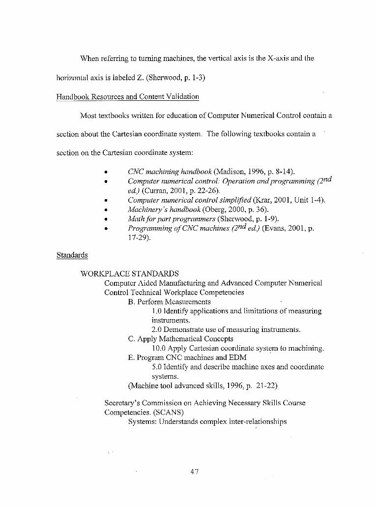
When referring to turning machines, the vertical axis is the X-axis and the
horizontal axis is labeled Z. (Sherwood, p. 1-3)
Handbook Resources and Content Validation
Most textbooks written for education of Computer Numerical Control contain a
section about the Cartesian coordinate system. The following textbooks contain a
section on the Cartesian coordinate system:
• CNC machining handbook (Madison, 1996, p. 8-14).• Computer numerical control: Operation and programming (2nd
ed.) (Curran, 2001, p. 22-26).• Computer numerical control simplified (Krar, 2001, Unit 1-4).• Machinery’s handbook (Oberg, 2000, p. 36).• Math for part programmers (Sherwood, p. 1-9).• Programming of CNC machines (2nd ed.) (Evans, 2001, p.
17-29).
Standards
WORKPLACE STANDARDSComputer Aided Manufacturing and Advanced Computer Numerical Control Technical Workplace Competencies
B. Perform Measurements1.0 Identify applications and limitations of measuring instruments.2.0 Demonstrate use of measuring instruments.
C. Apply Mathematical Concepts10.0 Apply Cartesian coordinate system to machining.
E. Program CNC machines and EDM5.0 Identify and describe machine axes and coordinate systems.
(Machine tool advanced skills, 1996, p. 21-22)
Secretary’s Commission on Achieving Necessary Skills Course Competencies. (SCANS)
Systems: Understands complex inter-relationships
47

A. Understands Systems - knows how social, organizational, and technological systems work and operates effectively with them.
Technology: Works with a variety of technologiesB. Applies Technology to Tasks - understands overall intent and proper procedures for setup and operation of equipment.
(What work requires of schools, 1991, p. 12)
CALIFORNIA CONTENT STANDARDS
MATHEMATICS Grade 4Measurements and Geometry
2.0 Students use two-dimensional coordinate grids to represent points and graph lines and simple figures (Mathematics framework for California public schools, 2000, p. 54).
MATHEMATICS Grade 5Algebra and Functions
1.0 Students use variables in simple expressions, compute the value of the expression for specific values of the variable, and plot and interpret the results (Mathematics framework for California public schools, 2000, p. 61).
MATHEMATICS Grades 8-12 Geometry
1.0 Students demonstrate understanding by identifying and giving examples of undefined terms, axioms, theorems, and reasoning (Mathematics content standards for California public schools, 1997, p. 51).
Mathematical Analysis1.0 Students are familiar with, and can apply, polar coordinates and vectors in the plane. In particular, they can translate between polar and rectangular coordinates and can interpret polar coordinates and vectors graphically (Mathematics content standards for California public schools, 1997, p. 58).
48
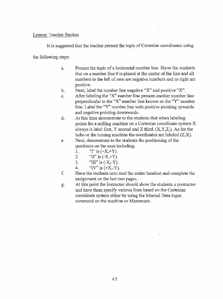
Lesson: Teacher Section
It is suggested that the teacher present the topic of Cartesian coordinates using
the following steps:
a. Present the topic of a horizontal number line. Show the students that on a number line 0 is placed at the center of the line and all numbers to the left of zero are negative numbers and to right are positive.
b. Next, label the number line negative “X” and positive “X”.c. After labeling the “X” number line present another number line
perpendicular to the “X” number line known as the “Y” number line. Label the “Y” number line with positive pointing upwards and negative pointing downwards.
d. At this time demonstrate to the students that when labeling points for a milling machine on a Cartesian coordinate system X always is label first, Y second and Z third. (X,Y,Z,). As for the lathe or the turning machine the coordinates are labeled (Z,X).
e. Next, demonstrate to the students the positioning of the quadrants on the axes including:1. “I” is (+X,+Y).2. “II” is (-X,+Y).3. “Ill” is (-X,-Y).4. “IV” is (+X,-Y).
f. Have the students next read the entire handout and complete the assignment on the last two pages.
g. At this point the instructor should show the students a protractor and have them specify various lines based on the Cartesian coordinate system either by using the Manual Data Input command on the machine or Mastercam.
49
Coordinate Systems Lesson: Student Handouts
Coordinate SystemsBy Paul A. Van Hulle
Cartesian or Rectangular Coordinates
When you have finished this assignment please have your instructor sign this sheet
in your signoff workbook.
Student Name:
Instructor’s signature
Competency achieved Yes or No:______
50

Cartesian or Rectangular Coordinates
The key to understanding numerical control is the rectangular coordinate system. Using the rectangular coordinate system any point in space can be described in mathematical terms.
Any point on a plane can be located by specifying its distance from each of two intersecting lines. When locating points on a workplace, take two straight, intersecting lines, one horizontal and one vertical making right angles with each other. These lines are called "axes" and their intersection point is called the "origin", "datum", or "zero point". The vertical axis is called the Y-axis; the horizontal axis is called the X-axis. The X and Y-axis designation can be applied to milling, boring and drilling machines.
When referring to turning machines, the vertical axis is the X-axis and the horizontal axis is labeled Z (Sherwood, p. 1).
51

Figure 1 - Mill axes(Sherwood, p. 2)
+x
52

Figure 2 - Lathe axes(Sherwood, p. 2)
+z
53

In figure 3, point “A” may be described as being located 3 units to the right of the Y-axis and 2 units above the X-axis. However, in order to avoid saying “to the left of’ and “to the right of’, “below” or “above”. Values to the right of the Y-axis are positive (+) and to the left are negative (-). Distances above the X-axis are positive and below are negative.
Locate B in Figure 3. It is 4 units to the right of the Y-axis and 3 units below the X-axis. Therefore the position of B is X = +4, Y = -3.
As a rule, the distance to the right or left of the Y-axis is given first and the distance above or below the X-axis is given second (Sherwood, p. 3).
+Y
AA
ci:JZ >
--- 1 p--
-Y
+X
Figure 3 - Point location with coordinates
(Sherwood, p. 2)
54

Y
-Y
Mill coordinate
+X
Lathe coordinate system Figure 4 -- Coordinate system quadrants
The graph formed by the intersections of.the two axes can be divided into four parts called quadrants. Quadrant 1 is the upper right section. Quadrants 2, 3 and 4 are located in a counterclock-wise direction from Quadrant 1. (See Figure 4)
When the rectangular coordinate system is shifted from the blue print to the table of a machine tool, we have the necessary dimensions for numerical control.
Simple two axis drilling machines are based on the coordinate system.
55

As an example, assume that the diagram in Figure 5 represents a drilling machine table and that there is a workpiece located in the upper right quadrant. The origin or datum point would be located on the lower left corner of the workpiece. The series of drill holes in the workpiece are specified by locations in the X-Y coordinate values. All values are positive because the points are in the 1st quadrant.
Point 1 in figure 5 is located at:X1.Y1.
Point 2 is located at: XI.Y4.Point 3: X5.Y1.Point 4: X5.Y4.
(Sherwood, p. 4)
+Y
-Y
Figure 5 - Drill table (Sherwood, p. 4)
56

Figure 6 — Mill Coordinates.By using a third plane or dimension called the Z-axis, which is
perpendicular to the plane comprised of the X and Y axes, more complicated work can be. completed.
Using the previous example of drilling holes in a flat workpiece in the X- Y plane, if the hole depth is given as a specific distance along the Z-axis, we have the use of 3 axis programming. For example if the holes in figure 5 are .25 deep and the top of stock is ZO. The 3 axis coordinates would be specified as:
Point 1: XI.Y1.Z-.25 Point2: X1.Y4.Z-.25 Point3: X5.Y1.Z-.25 Point 4: X5.Y4.Z-.25
(Sherwood, p. 5) ■,
57

Exercise 1 -- Mill Coordinate System
Refer to the points plotted on the illustrated Cartesian coordinate plane of a milling machine and determine the values of the corresponding X and Y locations. See Figure 7.
+Y
Figure 7 - Mill coordinate system
A X1.Y3,B ____________C ____________D____________E ____________F ____________G____________H____________
I ____________J ____________K____________L ____________M____________N____________O__________P ___________
Name:______________Date:_______________
58

Exercise 2 — Lathe Coordinate System
Refer to the points plotted on the illustrated Cartesian coordinate plane of a lathe machine and determine the values of the corresponding X and Z locations. See Figure 8.
+x
Figure 8 - Lathe coordinate system
A____________B Z2.X4,C _________ __D____________E ____________F ____________G____________H____________
I ____________J ____________K____________L ____________M____________NO__________P _________ __
Name:_______________Date:________________
59
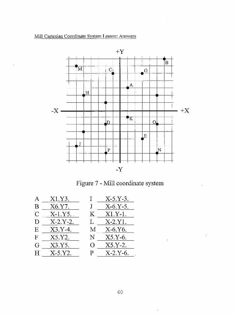
Mill Cartesian Coordinate System Lesson: Answers
+Y
Figure 7 - Mill coordinate system
A XI. Y3. I X-5.Y-3.B X6.Y7. J X-6.Y-5,C X-1.Y5.. K Xl.Y-1.D X-2.Y-2, L X-2.Y1.E X3.Y-4. M X-6.Y6.F X5.Y2. N X5.Y-6.G X3.Y5. O X5.Y-2.H X-5.Y2, P X-2.Y-6.
60

Lathe Cartesian Coordinate System Lesson: Answers
X
-X
Figure 8 - Lathe coordinate system
A Z1.X1. I Z-5.X-3.B Z2.X4, J ZO.X-4.C Z0.X5. K Z4.X0.D Z-2.X-2. L Z-5.X0.E Z5.X-5. M Z-6.X-5.F Z3.X2. N Zl.X-6.G Z6.X4, O Z3.X-4,H Z-2.X1. P Z-4.X-6,
61

Special thanks to Math for part programmers for providing the Cartesian
coordinate system assignment student handout. (Sherwood Media)..
62

POLAR COORDINATE SYSTEM FOR CNC PROGRAMMING
Overview
Grade Level: College
Time: One half Hour
Subjects: Math, Geometry
Objectives:
At the conclusion of these activities the student will be able to:
• Specify points in space using the Polar coordinate system.
• Describe the relationship of the Polar coordinate system to
Computer Numerical Control and Computer Aided Drafting.
• Complete a diagram of points using Polar Coordinates.
Introduction
Some CNC controls, Mastercam, and AutoCAD use polar coordinates to define
the location of points. Polar coordinates define the position of a point by its distance
and angle from a fixed reference point. The distance between points represents a radius
value and the direction refers to the angle between the positive X-axis and the point to
be defined.
Handbook Resources and Content Validation
The polar coordinate system was addressed in many of the textbooks about
Computer Numerical Control programming. The following textbooks contain a section
on the polar coordinate system:
63

• Computer numerical control: Operation and programming (2nd ed.) (Curran, 2001, p. 27).
• Machinery’s handbook (Oberg, 2000, p. 36).• Math for part programmers (Sherwood, p. 20-22).• Programming of CNC machines (2nd ed.) (Evans, 2001, p. 21).
Standards
WORKPLACE STANDARDSComputer Aided Manufacturing and Advanced Computer Numerical Control Technical Workplace Competencies
B. Perform Measurements1.0 Identify applications and limitations of measuring instruments.2.0 Demonstrate use of measuring instruments.
C. Apply Mathematical Concepts13.0 Perform polar trigonometric calculations.
E. Program CNC machines and EDM5.0 Identify and describe machine axes and coordinate systems.
(Machine tool advanced skills, 1996, p. 21-22)
Secretary’s Commission on Achieving Necessary Skills Course Competencies. (SCANS)
Systems: Understands complex inter-relationshipsA. Understands Systems - knows how social, organizational, and technological systems work and operates effectively with them.
Technology: Works with a variety of technologiesB. Applies Technology to Tasks - understands overall intent and proper procedures for setup and operation of equipment.
(What work requires of schools, 1991, p. 12)
CALIFORNIA CONTENT STANDARDS
MATHEMATICS Grades 8-12 Trigonometry
15.0 Students are familiar with polar coordinates. In particular, they can determine polar coordinates of a point given in rectangular coordinates and vice versa.
64

(Mathematics content standards for California public schools, 1997, p. 48).
Geometry1.0 Students demonstrate understanding by identifying and giving examples of undefined terms, axioms, theorems, and reasoning (Mathematics content standards for California public schools, 1997, p. 51).
Mathematical Analysis1.0 Students are familiar with, and can apply, polar coordinates and vectors in the plane. In particular, they can translate between polar and rectangular coordinates and can interpret polar coordinates and vectors graphically (Mathematics content standards for California public schools, 1997, p. 58).
Lesson: Teacher Section
It is suggested that the teacher present the topic of Cartesian coordinates using
the following steps:
a. First explain that the polar coordinate system is based on specifying the length and angle of a line (length of line<angle of line). Demonstrate the topic of a horizontal and a vertical line perpendicular to each other. The location of where the two lines cross represent the start of the desired line. Similar to a protractor, angles are specified based on degrees with 0 degrees pointing horizontally towards the right. One complete circle makes up 360 degrees with 360 divisions. From the crossing point of the two lines pointing to the right is 0 degrees, pointing straight upwards would be 90 degrees, pointing to the left is 180 degrees and pointing downwards represents 270 degrees.
b. Once the students understand the concept of how to specify points using the polar coordinate practice what was taught by completing the last page of the handout.
c. At this point the instructor should show the students a protractor and have them specify various lines based on the Polar coordinate system either by using the Manual Data Input command on the machine or Mastercam.
65
Polar Coordinate System Lesson: Student Handouts
Coordinate SystemsBy Paul A. Van Hulle
Polar CoordinatesWhen you have finished this assignment
please have your instructor sign this sheet in your signoff workbook.
Student Name:
Instructor’s signature
Competency achieved Yes or No:______
66
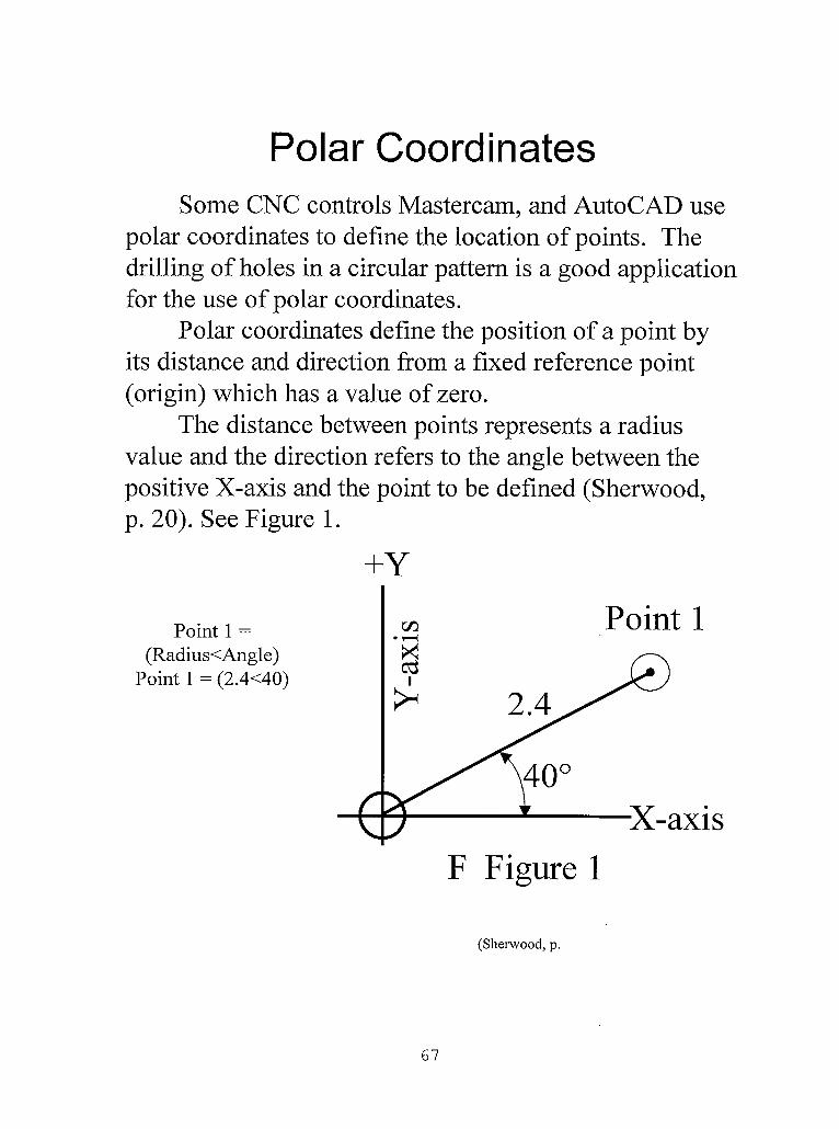
Polar CoordinatesSome CNC controls Mastercam, and AutoCAD use
polar coordinates to define the location of points. The drilling of holes in a circular pattern is a good application for the use of polar coordinates.
Polar coordinates define the position of a point by its distance and direction from a fixed reference point (origin) which has a value of zero.
The distance between points represents a radius value and the direction refers to the angle between the positive X-axis and the point to be defined (Sherwood, p. 20). See Figure 1.
(Sherwood, p.
67
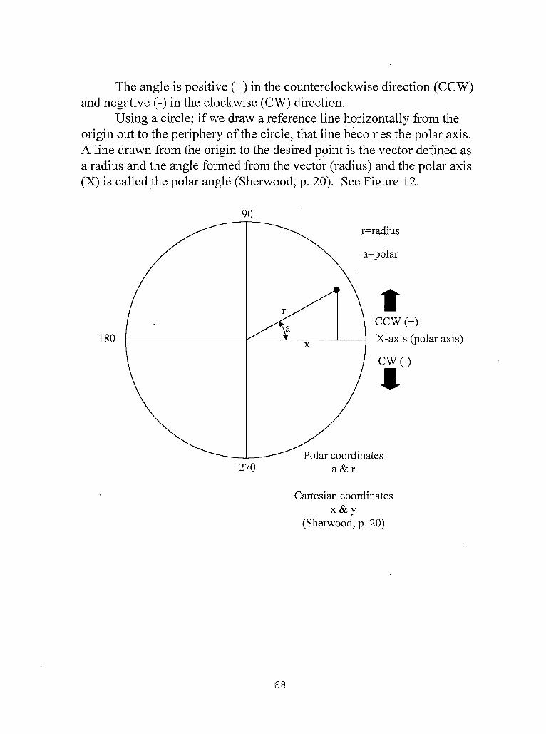
The angle is positive (+) in the counterclockwise direction (CCW) and negative (-) in the clockwise (CW) direction.
Using a circle; if we draw a reference line horizontally from the origin out to the periphery of the circle, that line becomes the polar axis. A line drawn from the origin to the desired point is the vector defined as a radius and the angle formed from the vector (radius) and the polar axis (X) is called the polar angle (Sherwood, p. 20). See Figure 12.
x & y(Sherwood, p. 20)
68

Problem: Give the polar coordinates of the drilled holes in the following example (Sherwood, p. 20).
2._____________3. _____________4. _____________5. _____________ Name:_____________________ _6. _____________ Date:_______________________7. _____________8. _____________
69

Polar Coordinate system Lesson: Answers
1. (2.5<15)2. (2.5<45)3. (2.5<90)4. (2.5<135)5. (2.5<165)6. (2.5<210)7. (2.5<270)8. (2.5<330)
70

Special thanks to Math for part programmers for providing the polar coordinate
system assignment student handout. (Sherwood Media).
71

ABSOLUTE AND INCREMENTAL (RELATIVE) MEASURING SYSTEMS FOR
CNC PROGRAMMING
Overview
Grade Level: College
Time: One hour
Subjects: Math, Geometry
Objectives:
At the conclusion of these activities the student will be able to:
• Describe the difference between incremental and absolute
• Differentiate between the G-codes used for specifying absolute
and incremental.
•
•
Describe the mistakes that can be made when machining in
incremental mode.
Specify locations of point positions and machine movement
using incremental and absolute coordinate systems.
Introduction
Two methods of specifying an endpoint or location are recognized by machine
control units, each dealing with the type of reference coordinate system designated by
the programmer or operator; one is called absolute, the other is called incremental.
Both use the same distance measurement system, whether decimal or metric, but differ
in their point of reference.
72

Handbook Resources and Content Validation
Details for teaching the difference between the absolute and incremental
measuring systems in a Computer Numerical Control education program was
addressed in many of the textbooks about Computer Numerical Control programming.
The following textbooks contain a section on the difference between the absolute and
incremental measuring systems:
• An introduction to CNC machining and programming (Gibbs, 1991, p. 124-125).
• Basic CNC operation. Training workbook (1994, p. 17-19).• CNC machining handbook (Madison, 1996, p. 47-50).• Computer numerical control: Operation and programming (2nd ed.)
(Curran, 2001, p. 27-28).• Computer numerical control simplified (Krar, 2001, Unit 7).• Machinery’s handbook (Oberg, 2000, p. 1248).• Mathfor part programmers (Sherwood, p. 10-19). •• Programming of CNC machines (2nc^ ed.) (Evans, 2001, p. 28, 264).
Standards
WORKPLACE STANDARDSComputer Aided Manufacturing and Advanced Computer Numerical Control Technical Workplace Competencies
B. Perform Measurements1.0 Identify applications and limitations of measuring instruments2.0 Demonstrate use of measuring instruments
C. Apply Mathematical ConceptsI. 0 Perform mathematical computations with calculator Calculate fractions and decimals with calculator10.0 Apply Cartesian coordinate systems to machiningII. 0 Perform trigonometric calculations
D. Read Blueprints2.0 Describe blueprint dimensions 4.0 Interpret blueprint drawings
E. Program CNC machines and EDM
73
2.0 Identify and describe machine operation nomenclature3.0 Identify and describe essentials of CNC systems 5.0 Identify and describe machine axes and coordinate systems.6.0 Describe and interpret CNC coding systems 7.0 Write NC programs
(Machine tool advanced skills, 1996, p. 21-22)
Secretary’s Commission on Achieving Necessary Skills Course Competencies. (SCANS)
Systems: Understands complex inter-relationshipsA. Understands Systems - knows how social, organizational, and technological systems work and operates effectively with them.
Technology: Works with a variety of technologiesB. Applies Technology to Tasks - understands overall intent and proper procedures for setup and operation of equipment.
(What work requires of schools, 1991, p. 12)
Lesson: Teacher Section
It is suggested that the teacher present the topic of incremental and absolute
coordinate systems using the following steps:
a. The first topic that should be presented is absolute coordinate system. Students should understand that in the absolute measuring system (coordinate) uses a fixed reference point (origin). All the locations to which the tool will be moved must be given dimensions relating to that original reference point. In other words in the absolute coordinate system 0,0 or the origin of the part always remains in the same place.
b. Once the students understand the essential concept of absolute coordinates they should complete the assignment on the absolute side of the mill axis assignment in the student handout. In this assignment students are asked to specify points for an actual dimensioned blueprint. Students should have already received instruction on reading a blueprint, subtraction and addition of decimals, and trigonometry.
c. After completing this assignment the instructor should give the details of the incremental coordinate system. The incremental measuring
7 4

system uses a floating reference point. Each new location uses the last location as a reference point each time the tool is moved. ■
d. The students should complete the incremental side of the assignment.e. The students should next be introduced to how to set the machine for
using absolute and incremental coordinates. Than show the students how to manually input coordinates on the machine using both incremental and absolute coordinates.
75
Absolute and Incremental Measuring Systems Lesson: Student Handouts
MeasurementSystems
By Paul A. Van Hulle
Absolute and Incremental
When you have finished this assignment please have your instructor sign this sheet
in your signoff workbook.
Student Name:
Instructor’s signature
Competency achieved: Yes or No:______
76
Measurement Systems
Two methods of specifying an endpoint or location are recognized by machine control units, each dealing with the type of reference coordinate system designated by the programmer or operator; one is called absolute, the other is called incremental. Both use the same distance measurement system, whether decimal or metric, but differ in their point of reference(Sherwood, p. 10).
77
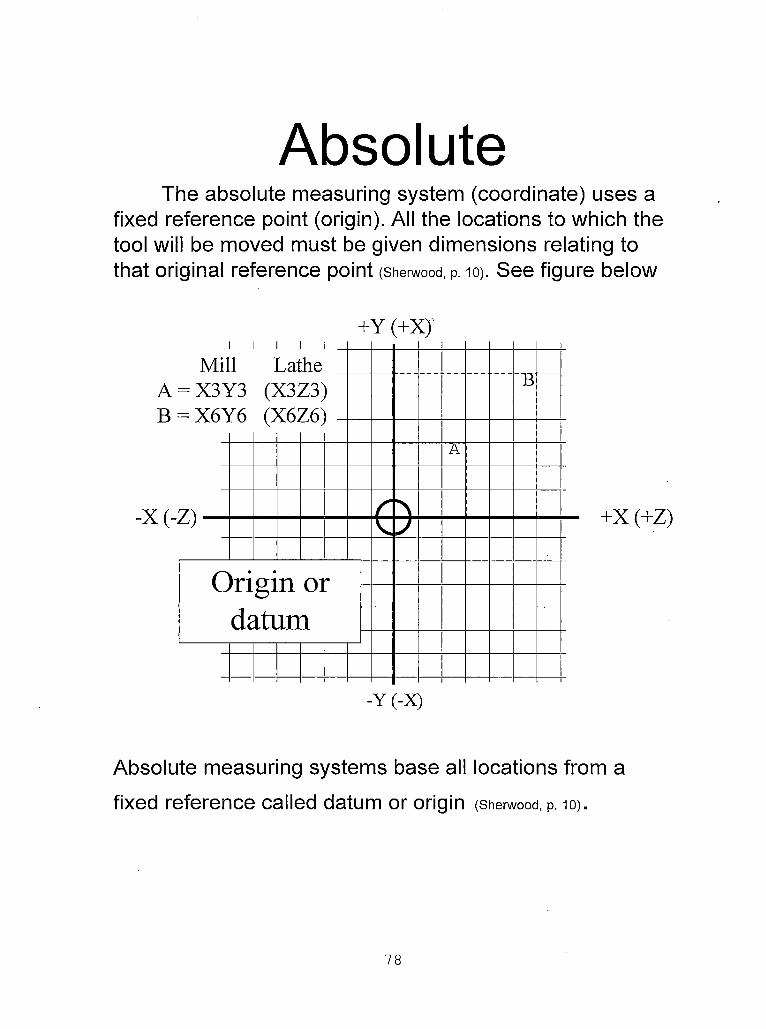
AbsoluteThe absolute measuring system (coordinate) uses a
fixed reference point (origin). All the locations to which the tool will be moved must be given dimensions relating to that original reference point (Sherwood, p. 10). See figure below
+Y (+XJ
Absolute measuring systems base all locations from a fixed reference called datum or origin (Sherwood, p. 10).
78
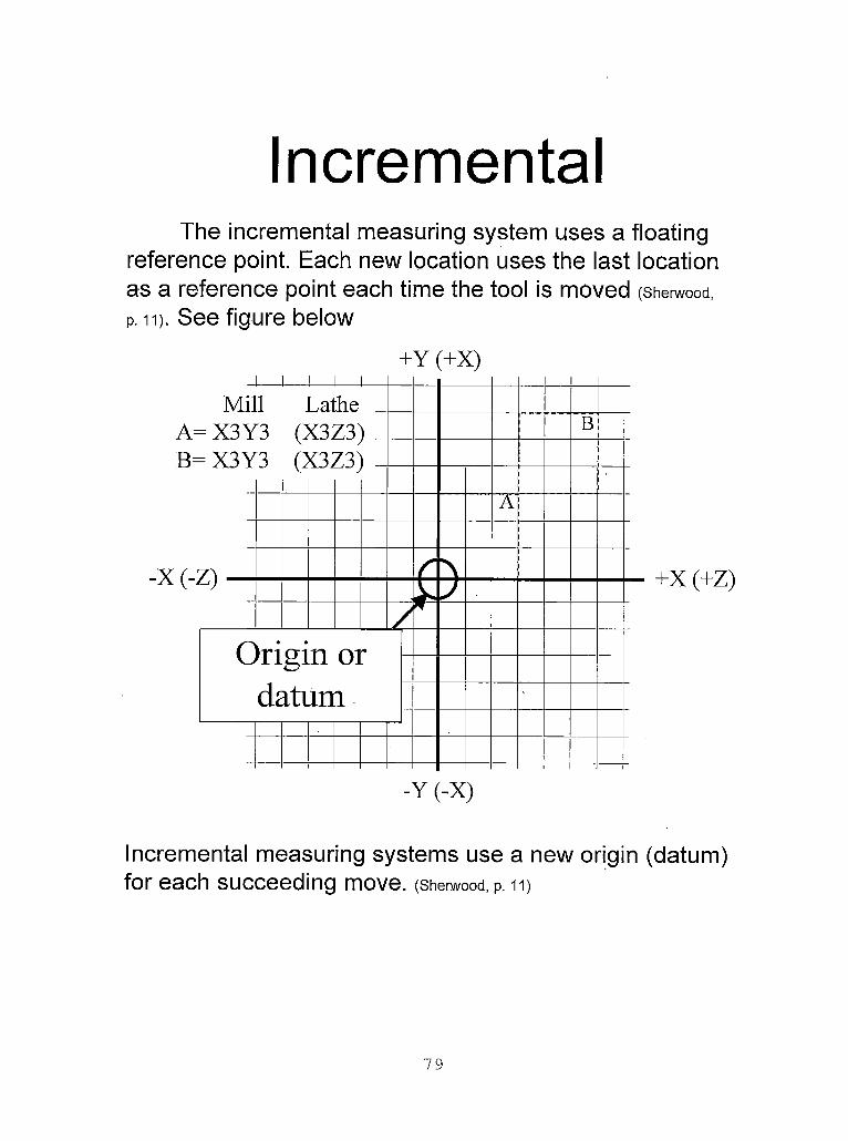
IncrementalThe incremental measuring system uses a floating
reference point. Each new location uses the last location as a reference point each time the tool is moved (Sherwood,
p. it). See figure below
+Y (+X)
+X (+Z)
Incremental measuring systems use a new origin (datum) for each succeeding move. (Sherwood, p. 11)
79

Directions: List X & YName:_________________ coordinates for points 1-20 onDate:___________________ the following drawing in both
absolute and incremental measuring systems (Sherwood, P. 12)
ABSOLUTE INCREMENTALX Y X Y
1
2
3
4
5
6
7
8
9
10
11
12
13
14
15
16
17
18
19
20
80

5 .062
12
4,7500
$,5525

Absolute and Incremental Measuring Systems Lesson: Answers
ABSOLUTE INCREMENTALX Y X Y
1 0 0 0 02 0 1.3125 0 1.31253 0.75 2.0625 0.75 0.754 0 2.8125 -0.75 0.755 0 3.6875 0 0.8756 1.0625 3.6875 1.0625 07 1.0625 4.75 0 1.06258 2.75 4.75 1.6875 09 3 4.5 0.25 -0.25
10 4.1875 4.5 1.1875 011 4.4375 4.75 0.25 0.2512 5.0625 4.75 0.625 013 6.5625 3.25 1.5 -1.514 6.5625 1.3125 0 -1.937515 5.25 1.3125 -1.3125 016 5.25 0 0 -1.312517 3.0625 0 -2.1875 018 3.0625 0.5 0 0.519 1.5 0.5 -1.5625 020 1.5 0 0 -0.5
82

Special thanks to Math for part programmers for providing the absolute and
incremental assignment student handout. (Sherwood Media).
83
COMPUTER AIDED MACHINING USING MASTERCAM
ZOOMING AND MUNIPULATING VIEWS
Overview
Grade Level: College
Time: One Hour
Subjects: Computer Aided Machining/Computer Aided Drafting, Computers
Objectives:
At the conclusion of these activities the student will be able to:
• Apply Mastercam’s zoom commands to zoom in and out of a
drawing in order to produce detailed drawings.
• Apply techniques to manipulate views for navigating in 3- '
deminsional drawings.
• Differentiate between zooming and the scale command.
• Demonstrate the use of the following commands:
■ Zoom’■ Unzoom■ Scale geometry■ Fit geometry■ Repaint
Introduction
When producing detailed drawings for part creation the student must
understand how to zoom into different parts of the drawing.
84
Handbook Resources and Content Validation
Many textbooks about CAD/CAM dedicate a section to teaching how to zoom
into different parts of a drawing. The following textbooks contain a section on
zooming and manipulating views:
• Mastercam Handbook, Volume 1 (Mastercam Handbook, 2001, p. 2-20).
• Mastercam Version 7 (Lin, 1998, p. 3-6).Standards
WORKPLACE STANDARDSComputer Aided Manufacturing and Advanced Computer Numerical Control Technical Workplace Competencies
G. Use Computers1.0 Demonstrate use of computer hardware
I. Using CAD/CAM programs1.0 Demonstrate understanding of CAD/CAM programs2.0 Access CAD program options3.0 Create designs with CAD section of CAD/CAMprogram4.0 Demonstrate ability to use program functions
(Machine tool advanced skills, 1996, p. 21-22)
Secretary’s Commission on Achieving Necessary Skills Course Competencies. (SCANS)
Systems: Understands complex inter-relationshipsA. Understands Systems - knows how social, organizational, and technological systems work and operates effectively with them.
Technology: Works with a variety of technologiesB. Applies Technology to Tasks - understands overall intent and proper procedures for setup and operation of equipment.
(What work requires of schools, 1991, p. 12)
85

Lesson: Teacher Section
The handout provided for the lesson is fairly self-explanatory. The student
should be able to follow the directions of the lesson handouts and perform the
activities virtually without teacher’s assistance.
86

Zooming and Manipulating Views for Mastercam Lesson: Student Handouts
MastercamBy Paul A. Van Hulle
Zooming and Manipulating Views
When you have finished this assignment please have your instructor sign this sheet
in your signoff workbook.
Student Name:
Instructor’s signature
Competency achieved Yes or No:______
87
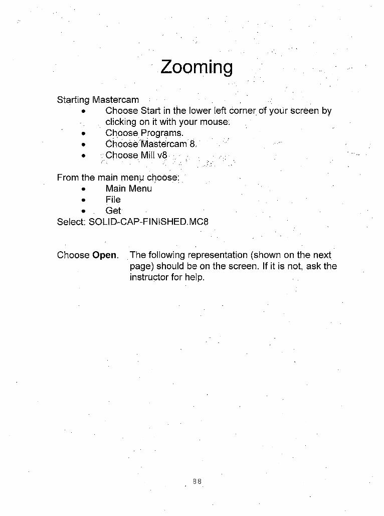
Starting Mastercam• Choose Start in the lower left corner of your Screen by
clicking on it with your mouse:• Choose Programs.• Choose Mastercam 8.• Choose Mill v8
From the main menu choose:• Main Menu• File• Get
Select: SOLID-CAP-FINISHED.MC8
Choose Open. The following representation (shown on the next page) should be on the screen. If it is not, ask the instructor for help.
88

• Refer to your Mastercam Default keyassignments handout (In the middle of Page A- 7) and look up which command makes shading active.
■ i, M.isteicjin MilIV.-i inn U U H II S nnnAHIZI KClfWI I lillX LIDV4JI ll> TAP NMISHFI) MBH
/■'ip i/'Qi Scjhuii:
< iinliqiup Statistics Hulpu lilts Cli luIuis I hq (nliiis
Cluj IpvpIs Cliq .illiilis
Surf fli'ip Kl.-mk lll'Xl IIIPIlll
BACKUP MAIil Ml Nil
/■ lE'idlin Culm: i?
I i;vcI: 1 Style Wiillli
turnips Musk: Oil T|)l(iue:O(-l- Cpluiie: T (iview: I
J^St.ulJ Exploring • pwel bo B Microsoft Pc werPoi | ^CD Player
|, 1226 PM|[ *, <M<isl'*ii,<]in Mill * 1 I ■
The above representation should be on the screen. If it is not, ask the instructor for help. (Note: you may have a black background. I use a white background during presentations to decrease the amount of ink used.)
89
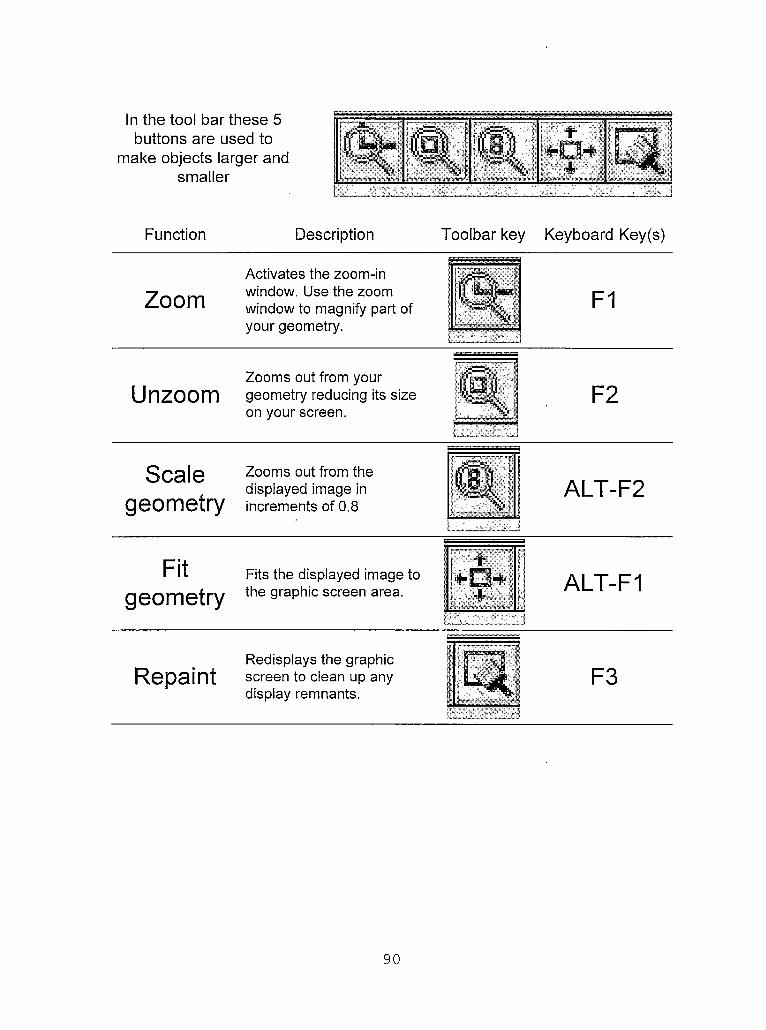
In the tool bar these 5 :buttons are used to
make objects larger and smaller
W tI+O+
.EM,
r - - .
Function Description Toolbar key Keyboard Key(s)
ZoomActivates the zoom-in window. Use the zoom window to magnify part of your geometry.
I
F13
w
Zooms out from yourUnzoom geometry reducing its size F2
on your screen.—
Scale Zooms out from thedisplayed image in ALT-F2geometry increments of 0.8
7“
Fit Fits the displayed image to •fM
3II!
4k
11 ALT-F1
geometry the graphic screen area.
dI
Redisplays the graphicRepaint screen to clean up any F3
display remnants.
90

Try zooming in on the large circle of the solid cap
2. Next, use the Fit command to fit the geometry to the size of the screen.
3. Then, use the scale geometry command to unzoom the geometry by 0.8
4. Next, use the Fit command to fit the geometry to the size of the screen.
5. Then, use the unzoom command to unzoom the geometry by 0.5.
6. Repeat steps 2-5 and compare the difference in size of the geometry between the scale geometry and the unzoom command.
91

Manipulating ViewsStarting Mastercam
• Choose Start in the lower left corner of your screen by clicking on it with your mouse.
• Choose Programs.• Choose Mastercam 8.• Choose Mill v8
From the main menu choose:• Main Menu• File• Get
Select: SOLID-CAP-FINISHED.MC8
Choose Open. The following representation (shown on the next page) should be on the screen. If it is not, ask the instructor for help.
92

Refer to your Mastercam Default key assignments handout (In the middle of Page A-7) and look up which command makes shading active.
Mastercam Mill Version 8.0- H:\PAIII S OBGANIZEDUEWEL BOX I ll)\c.ni ID-CAP-FINISHED.MCH
up ? IT X? <P>. eIgljgI -*
n
Screen: ;= . ‘,Configure Statistics Endpoints Clr colors Chg colors Chg levels Chg attribs Surf (lisp Blank Next menu
'BACKUP MAIN MENU
I Z: -0.5000Moil ,;jh23 j Level:1"‘ j i jStyle/Wiillh
jSroups Mask. Oil
_T|)line:OFF_ Cplaiie: T
r Gview: I L-V''K
;,as7artl » fe] aj ia
i ■ s Exploring-jervei bo |i B Microsoft PowaPci.. [i f‘JCD Player rlMaslercam Mill... r 1 Hicrosott PoweiPci.
12:26 PM
The above representation should be on the screen. If it is not, ask the instructor for help. (Note: you may have a black background. I use a white background during presentations to decrease the amount of ink used.)
93

In the tool bar these 5 buttons are used to
manipulate how the object is viewed.
5. Choose from the tool bar menu
A view of the top of the work piece is shown.
6. Press [Alt] and [F1] at the same time to fit the drawing to the screen, or select the fit screen icon.
7. Choose• Gview (at the bottom of the screen)• Dynamic Gview:
Bring the cursor to the middle of the part and click the mouse. Now slowly move the mouse around and watch the part revolve and move around on the screen.Click the left mouse button again to hold that view.
94

COMPUTER AIDED MACHINING USING MASTERCAM
CREATING OBJECTS
Overview
Grade Level: College
Time: Two Hours
Subjects: Computer Aided Machining/Computer Aided Drafting, Computers
Objectives:
At the conclusion of these activities the student will be able to:
• Apply Mastercam’s creating objects commands to create drawings
• Apply Mastercam’s delete commands to erase objects
• Demonstrate the use of the following commands:■ Create line■ Create arcs and circles■ Create fillets■ Delete and undelete objects
Introduction
When producing detailed drawings for part creation the student must
understand how to create objects.
Handbook Resources and Content Validation
Many textbooks about CAD/CAM dedicate sections to teaching how to create
objects within Mastercam. The following textbooks contain a section on zooming and
manipulating views:
• Mastercam Handbook, Volume 1 (Mastercam Handbook, 2001, Chapters 2-4).
95

Mastercam Version 7 (Lin, 1998, Chapters 3-5).Standards
WORKPLACE STANDARDSComputer Aided Manufacturing and Advanced Computer Numerical Control Technical Workplace Competencies
G. Use Computers1.0 Demonstrate use of computer hardware
I. Using CAD/CAM programs1.0 Demonstrate understanding of CAD/CAM programs2.0 Access CAD program options3.0 Create designs with CAD section of CAD/CAM
program4.0 Demonstrate ability to use program functions
(Machine tool advanced skills, 1996, p. 21-22)
Secretary’s Commission on Achieving Necessary Skills Course Competencies. (SCANS)
Systems: Understands complex inter-relationshipsA. Understands Systems - knows how social, organizational, and technological systems work and operates effectively with them.
Technology: Works with a variety of technologiesB. Applies Technology to Tasks - understands overall intent and proper procedures for setup and operation of equipment.
(What work requires of schools, 1991, p. 12)
Lesson: Teacher Section
The handout provided for the lesson is fairly self-explanatory. The student
should be able to follow the directions of the lesson handouts and perform the
activities virtually without teacher’s assistance.
96

Creating Objects using Mastercam Lesson: Student Handouts
MastercamBy Paul A. Van Hulle
Creating Objects and Deleting Objects
When you have finished this assignment please have your instructor sign this sheet
in your signoff workbook.
Student Name:
Instructor’s signature
Competency achieved Yes or No:______
97

Creating and Deleting ObjectsStarting Mastercam
• Choose Start in the lower left corner of your screen by clicking on it with your mouse.
• Choose Programs.• Choose Mastercam 8.• Choose Mill v8
From the main menu choose:• ’Main Menu• ‘File• *Get
Select: rectang.MC8
Choose Open. The following representation (shown on the next page) should be on the screen. If it is not, ask the instructor for help.
98

DOS ’G'O b® £ /KV•VMastercam HiU Version 8.0 - C:\SAH JACINTO »1 SCHEATING 0BJECTS\RECTANG.MC7
Mam Menu*
1 iii) l’S|0 aiiX.14.13255 Y-7.51773
Analyze Create Filo' *ModifyKtorovQeieteScreenSftlidsToolpathsNC utils
□BACKUP____' MAW MENU
(nil~~T^a?
0.0000r: ’>Fitgrr
IpUm- OHCplanfl: T 'Gvlewn“T''
St.I.'.-.'1(111.
: OFF
Y+
Y=
The above representation should be on the screen. If it is not, ask the instructor for help. (Note: you may have a black background. I use a white background during presentations to decrease the amount of ink used.)
99

In the tool bar these 9 buttons
are used to create objects
'A ■' " tr- *fPI +1<$> f—71 “1
Using the keyboard pressing the underlined letter selects the -
command.
\ Keyboard Key(s)Function Description Toolbar key \From Main Menu
Createline
rActivates the line menu f(Used for making lines). / (glreate’Qine
Create ■ ■ .... 3
arcs and circles
Activates the arc menu (Used for making arcs).
irY
t ’
Create; Arc
Create Activates the fillet menu. =(FILLET rounds or fillets thefillets or edges of two lines, arcs, w Create; Filletrounds circles, or splines with an arc of a specified radius).
r a1 • r. i
r
before FILLET after FILLET
Createsplines
Activates the (A spline is a that is based of points).
spline menu smooth curve on a sequence
Create;Spline
CreateRectangle
Activates the rectangle menu.
Create;Rectangle
100

In the tool bar these 9 buttons
are used to create objects
Function DescriptionKeyboard Key(s)
Toolbar key From Main Menu
In the tool bar these 2 buttons are used to delete and undelete
objects
Deleteobject
The delete menu gives you options for deleting entities.
Delete
Undeleteobject
The undelete operation gives you the ability to restoring deleted entities. Mastercam restores entities in the reverse order in which they were deleted.
Delete;Undelete
101

Creating LinesCreate line Activates the line menu
(Used for making lines).Create;
Line
Line:HorizontalVerticalEndpointsMultiPolarTangentPerpendclrParallelBisectClosest
The line menu contains 10 different methods of creating lines. In this lesson you will learn about the first 6 including:Horizontal - used for creating lines at 0 or 180 degrees.
The command ask for:Enter two points for the endpoints of the line.In the prompt area, enter a value to position the line on the vertical axis.
Vertical - used for creating lines at 0 or 90 degrees.Enter two points for the endpoints of the line.In the prompt area, enter a value to position the line on the horizontal axis.
Endpoints - Creating a line between any two pointsEnter two points for the endpoints of the line.
Multi - Creating multiple lines connected at their endpoints Enter a point for the first endpoint of the first line. Enter a point for the second endpoint of the line. Press [Esc] to exit the function.
Polar - a line based on a distance and angle.Enter a point for the first endpoint of the line. In the prompt area, enter the angle of the line. Enter the length of the line.
Tangent - The Tangent Line menu gives you options for creating lines that are tangent to arcs and splines. Tangent means the line only passes through one point on the arc.
102

Creating Horizontal LinesHorizontal - used for creating lines at 0 or 180 degrees. *The command ask for: T
Enter two points for the endpoints of the line.In the prompt area, enter a value to position the line on the vertical axis.
Try this:Start the horizontal line, command:
MAIN MENUCreateLineHorizontalSpecify the start point at (0,1) by typing 0,1 fEnterl Enter the end point at 4,0(Notice that the line is actually sitting at 0,1 and 4,1. The reason.for this is Mastercam places the horizontal line at the vertical position of first point placement). .
The next prompt will ask you for where the line should be placed along the vertical axis Enter 4.0 Notice that the point is moved from y1 to y4.
Click on ESC or MAIN MENU
Note: Our main objective in drawing objects is to draw them accurately. This objective is obtained by using one of the following methods: entering points by typing their Cartesian coordinates, by using Mastercards AutoCursor or using point entry menu, (see below for more information about AutoCursor)
By entering points you define positions in 3D space.. You can enter point's using one of two methods: Mastercards AutoCursor™ feature or the Point Entry menu.
The AutoCursor™ is a point entry feature that is available whenever Mastercam displays the Point Entry menu and prompts you to enter a point. AutoCursor eliminates menu steps by detecting and snapping to points as you move the cursor over geometry on the screen.
Endpoints and midpoints of curves, arc center points, and point entities are all detected and highlighted by AutoCursor. If AutoCursor doesn’t detect any points, the AutoCursor defaults to the Sketch Point Entry menu option, letting you enter a point at any position.
At any time while AutoCursor is active, you can override the auto-selected point by using the mouse or keyboard shortcut keys to access Point Entry menu options. In complex geometry there may be more than one point that lies within the detection range of the cursor. In these cases, the AutoCursor uses the order shown below to detect and snap to points (Mastercam’s Help Menu, 2000, AutoCursor).
103

Creating Vertical LinesVertical - used for creating lines at 0 or 90 degrees.
Enter two points for the endpoints of the line.In the prompt area, enter a value to position the line on the horizontal axis.
Do this:Start the vertical line command:
MAIN MENU Create Line VerticalEndpoint (on the point entry menu)•Specify the start point at the right endpoint of the horizontal line. •Enter the end point at 4,0•The next prompt will ask you for where the line should be placed along the horizontal axis accept the default: 4.0
Your drawing should look like the above picture if it does not ask for help.
TOT

Creating Lines at EndpointsEndpoints - Creating a line between any two points
Enter two points for the endpoints of the line.tnopoinrIntersec[MidpointPointLastRelative
Do this:Start the endpoints line command:
MAIN MENU Create LineEndpoints Endpoint (on the point entry menu)Click on the left endpoint of the horizontal line■ Move your cursor over the midpoint of the vertical line. Notice the
sticky box comes on when you move over the midpoint. Also notice the midpoint line on the point selection menu turns white. This indicates that you are over the exact midpoint of that line.
■ With the sticky box on click on the midpoint of the vertical line.■ The line is placed at the midpoint of the vertical line.
Your drawing should look like the picture at the right if it does not ask for help.
105

Creating Lines using the Multi Command.
Endpoints - Creating a line between any two points Enter two points for the endpoints of the line.
Do this:Start the multi line command:
MAIN MENU Create Line Multilntersec(on the point entry menu).Click on the angled line and the verticalThe beginning of the multi line starts should start at the intersection of the two lines.
Go back to the main menu when you are finished.
106

Deleting Objects.In the tool bar these 2 buttons
are used to delete and undelete objects
We will revisit the line commands on the next page.
Deleteobject
The delete menu gives you 0 options for deleting entities. H
DeleteJ
gives you the ability to ?Undelete restore deleted entities. jj. Delete;
objectMastercam restoresentities, in the reverse i Undeleteorder in which they were ■"deleted.
Do this:Start the delete command:
MAIN MENUDeleteChainSelect on one of your linesIf you have completed the previous activities all of your lines should be selected for deletion y^Click on Done; all your lines should
disappear.Go back to the main menu when
you are finished
Your drawing should look like the picture at the right.
Y-
107

Creating Lines using the Polar Command.
Polar - a line based on a distance and angle.Enter a point for the first endpoint of the line.. In the prompt area, enter the angle of the line. Enter the length of the line.
Do this:Start the polar line command:
MAIN MENU Create Line Polar First line:
- Start point: 0,0 Angle in Degrees: 0 Distance: 4
Second line:Start point: 0,0 Angle in Degrees: 45 Distance: 4
Compare the difference between the first line and the second. While both the second and first line have the same length, the major difference between the first and second line is the second line is rotated slightly (at 45 degrees from 0 degrees).
Recall the polar coordinate system lesson; any of these angles from that lesson can be used.
Click on ESC when you are finished.
Try these lines:
Start point: 0,0Angle in Degrees: 135 Distance: 4
Start point: 0,0Angle in Degrees: 165 Distance: 4
Start point: 0,0Angle in Degrees: 210 Distance: 4
Start point: 0,0Angle in Degrees: -35Distance: 4
Go back to the main menu when you are finished
108

Deleting Objects.In the tool bar these 2 buttons
are used to delete and undelete objects
We will revisit the line commands on the next page.
Delete The delete menu gives you options for deleting Deleteobject entities. r% JThe undelete operation gives you the ability to
I
Undelete restore deleted entities. liiilli Delete;object
Mastercam restores 1-entities in the reverse order in which they were deleted.
? Undelete
Do this:Start the delete command:
MAIN MENU DeleteSelect all of the entities that you created during the previous screen.Click on Done; all your lines should disappear.Click on ESC when you are finished.
Your drawing should look like the picture at the right.
Y=
109

Uses for Creating Lines using the Polar Command
The create, line, polar (C,L,P) command can be used almost exclusively to rapidly create 2d drawings. For example, consider the rocker beam pictured below.
Do this: Start the polar line command:MAIN MENU Create Line Polar First line:
Start point: 0,0 Angle in degrees: 0 Distance: 2+11/32
Second line:Start point: endpoint of the first line (use the sticky box or the endpoint selection method to select the exact endpoint of the first line)Angle in degrees: 90 Distance: 3/8
Third line:Start point: endpoint of the second line Angle in degrees: 180 Distance: 3/4
-2-11/32 -2-56 x 1/8" deep .187
° L-3/16ream 3/16"
ROCKER BEAM aluminum 1 required
Feel free to zoom in or out as needed.
Continued on the next page
110

Uses for Creating Lines using thePolar Command (Cont.)
Fourth line:Start point: .endpoint of the third lineAngle in degrees: 270 Distance: 1/8
Fifth line:Start point:endpoint of thefourth lineAngle in degrees: 180Distance:
2+11/32-1/4-3/4 Sixth line:
Start point: endpoint of the Fifth lineAngle in degrees: 90 Distance: 3/4
Seventh line:Start point:endpoint of the
ROCKER BEAM aluminum 1 required
Sixth line As you can see, the C,L,P commandAngle in degrees: 180 Distance: 1/4
Eighth line:Start point:endpoint of the
can be used to rapidly create simple 2d drawings!
seventh line: Go back to the Main Menu when are finishedAngle in degrees: 270 Distance: 1
Feel free to zoom in or out as needed.
in

Deleting Objects.In the tool bar these 2 buttons
are used to delete and undelete objects
We will revisit the line commands on the next page.
Delete The delete menu gives you V Deleteobjectoptions for deleting entities.
•1•
---- .The undelete operation ■iigives you the ability to
Undelete restore deleted entities. III ! Delete;
objectMastercam restoresentities in the reverse
J * J Undeleteorder in which they were deleted.
Do this:Start the delete command:
MAIN MENUDeleteChainSelect on one of your linesIf you have completed the previous activities all of your lines should be selected for deletionClick on Done; all your lines Y^
should disappear.Go back to the main menu when
you are finished
Your drawing should look like the picture at the right.
112
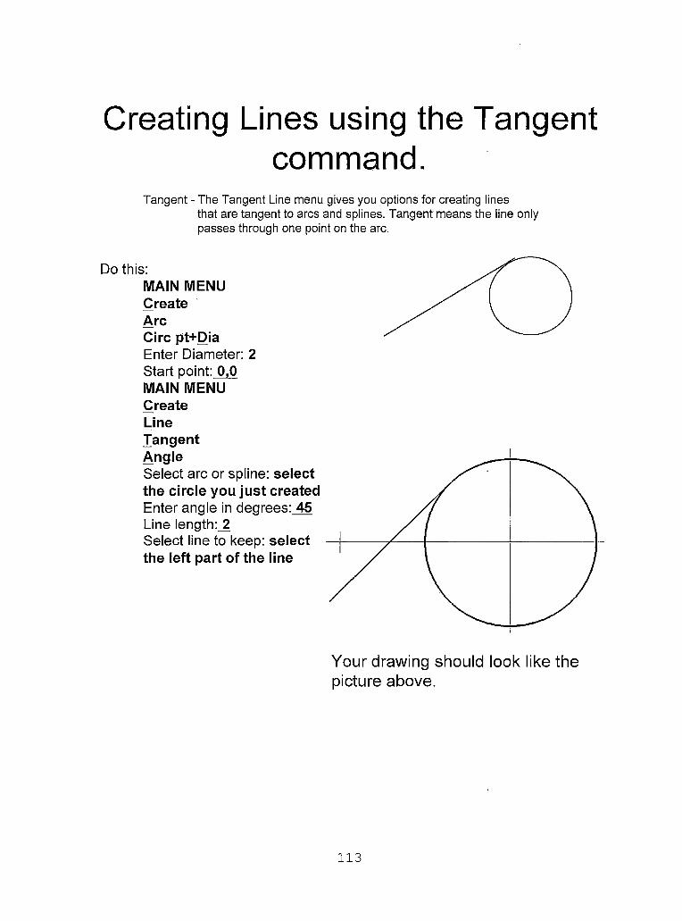
Creating Lines using the Tangent command.
Tangent - The Tangent Line menu gives you options for creating linesthat are tangent to arcs and splines. Tangent means the line only passes through one point on the arc.
Do this:MAIN MENUCreateArcCirc pt+DiaEnter Diameter: 2 Start point: 0,0MAIN MENUCreateLineTangent
Your drawing should look like the picture above.
113

Creating Lines using the Tangent command.
Tangent - The Tangent Line menu gives you options for creating linesthat are tangent to arcs and splines. Tangent means the line only passes through one point on the arc.
Do this:MAIN MENUCreateArcCirc pt+RadiusEnter Radius: 1 Start point: 2,2MAIN MENUCreateLineTangent2 ArcsSelect an arc: select the bottom side of the first circleSelect another arc: Select the bottom side of the second circleNote: Select both entities close to where you want to create the tangent line because multiple solutions may be possible.
Your drawing should look like the picture at the right.
114
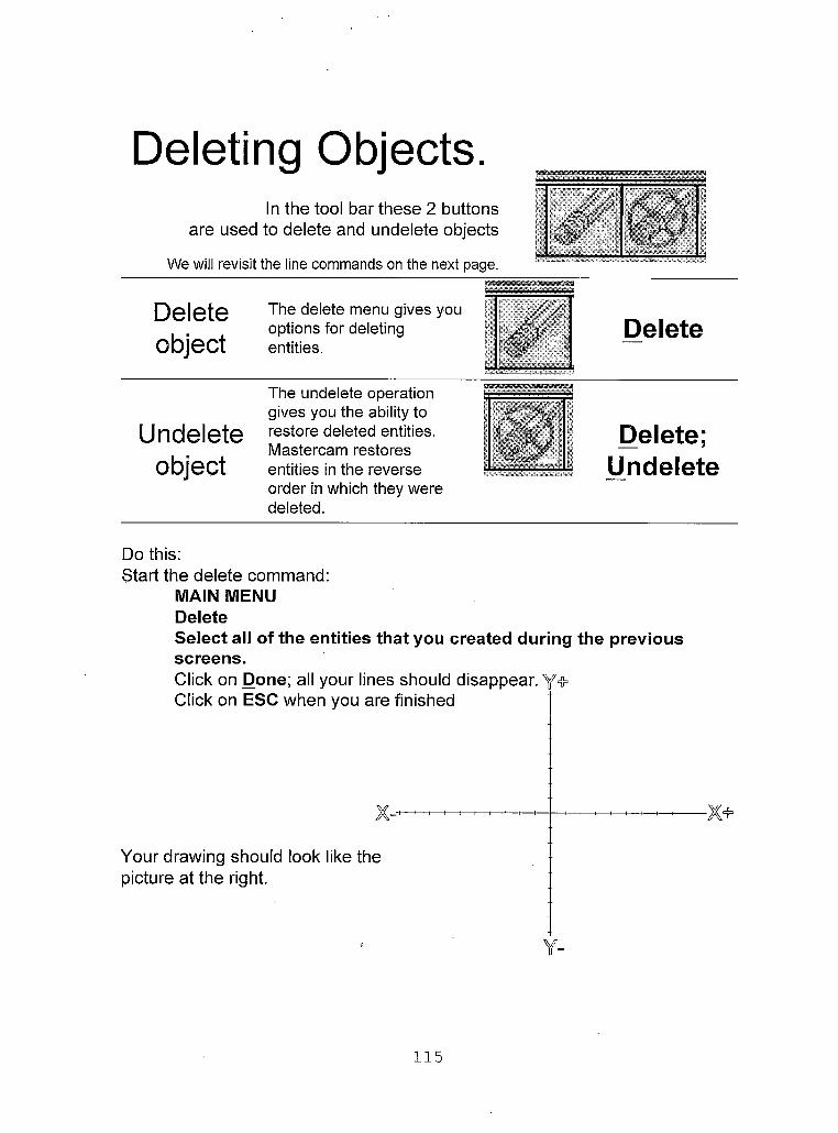
Deleting Objects.In the tool bar these 2 buttons
are used to delete and undelete objects
We will revisit the line commands on the next page.
Delete The delete menu gives youoptions for deleting Deleteobject entities. . J'
Thfi unrlfilfitfi nnpratinn —— ....
gives you the ability toUndelete restore deleted entities. ll^mi Delete;
Mastercam restores *object entities in the reverse y Undelete
order in which they weredeleted.
Do this:Start the delete command:
MAIN MENU DeleteSelect all of the entities that you created during the previous screens.Click on Done; all your lines should disappear. Y#Click on ESC when you are finished
Your drawing should look like the picture at the right.
115

Creating ArcsCreate
arcs and circles
Arc:Polar Endpomts 3 points Tangent Circ 2 pts Ch e 3 pts Circ pt+rad Circ pt+dia Circ pt+ed(j
Activates the arc menu (Used for making arcs). r\ Create; Arc
The line menu contains 9 different methods for creating arcs. Please see the Mastercam help menu if you need to learn more about the other types of arcs. The four that I have detailed on the next few pages are enough to get you started in Mastercam. In this lesson you will learn about the following 4 including:
• Circ pt+dia - Creating a circle with a defined center point and diameter.
0 Circ pt+rad - Creating a circle with a defined center point and radius.
• Polar - The Polar Arc menu gives you options for creating arcs using Polar coordinates.
0 Fillet - The Fillet command (found in the create and the modify menu) gives you options for filleting curves. When you fillet curves, you insert an arc of a defined radius tangent to the curves. You can access the Fillet menu by choosing Main Menu, Modify, Fillet or by choosing Main Menu, Create, Fillet.
0 Tangent - The Tangent Arc menu gives you options for creating arcs that are tangent to curves and points.
116

Creating Arcs using Circ pt+DiaCreating a circle with a
defined center point and diameterConsider the drawing of the Rod Support located at the right; during the next screen you will use the Circ pt+Dia command to add the 3 circles to this drawing.
117
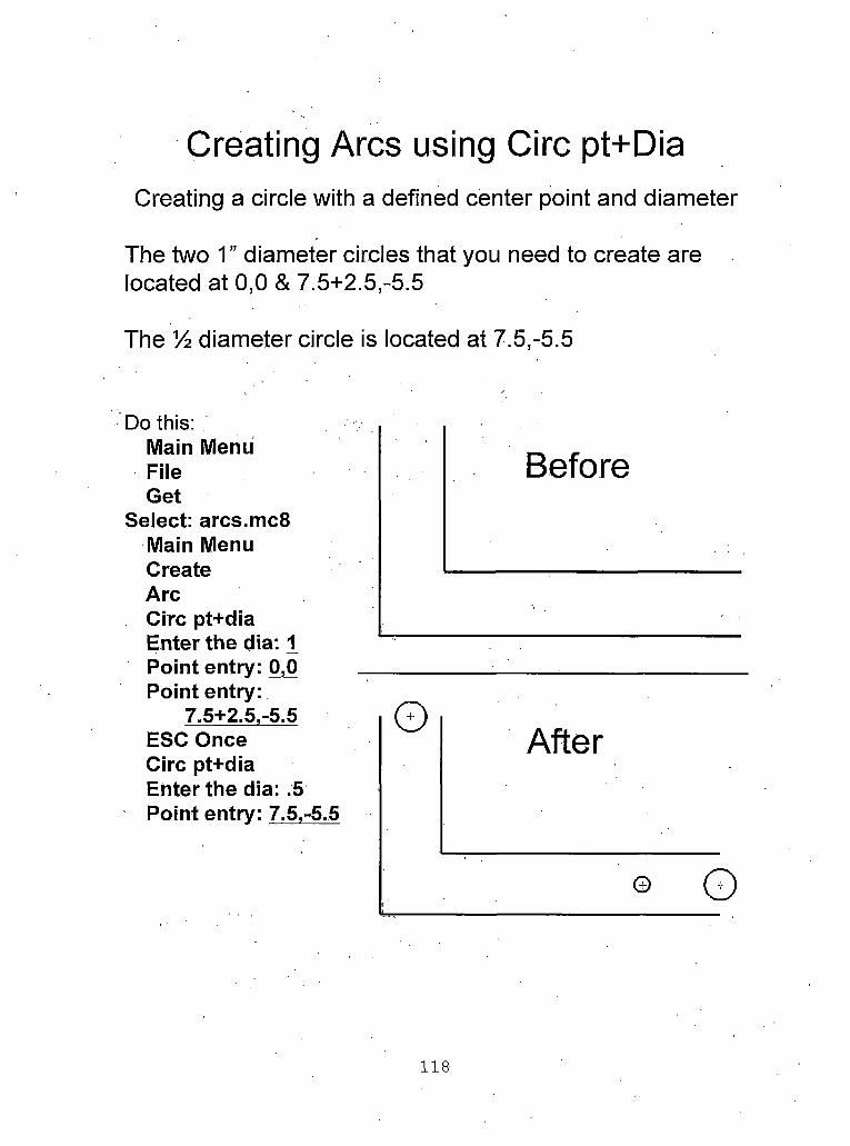
Creating Arcs using Circ pt+DiaCreating a circle with a defined center point and diameter
The two 1 ” diameter circles that you need to create are located at 0,0 & 7.5+2.5,-5.5
The % diameter circle is located at 7.5,-5.5
Do this:Main MenuFileGet
Select: arcs.mc8 Main Menu Create ArcCirc pt+dia Enter the dia: 1 Point entry: 0,0 Point entry:
7.5+2.5,-5.5 ESC Once Circ pt+dia Enter the dia: .5 Point entry: 7.5,-5.5
After
© 0
118
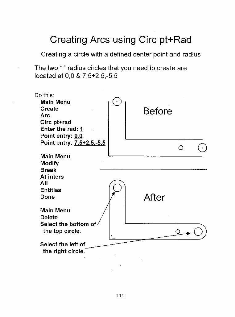
Creating Arcs using Circ pt+RadCreating a circle with a defined center point and radius
The two 1” radius circles that you need to create are located at 0,0 & 7.5+2.5,--5.5
Do this:Main MenuCreateArcCirc pt+rad Enter the rad: 1 Point entry: 0,0 Point entry: 7.5+2.5,-5.5
Main Menu ModifyBreak —
Before
© ©
119
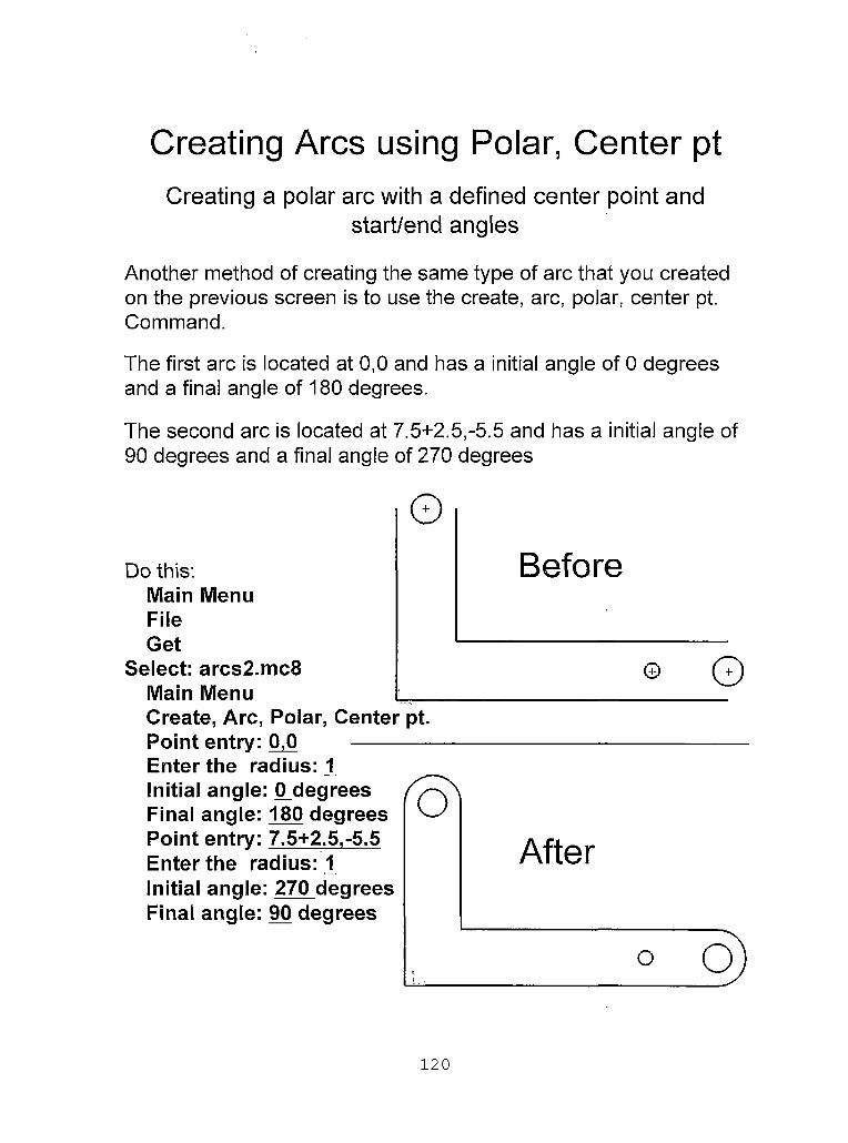
Creating Arcs using Polar, Center ptCreating a polar arc with a defined center point and
start/end angles
Another method of creating the same type of arc that you created on the previous screen is to use the create, arc, polar, center pt. Command.
The first arc is located at 0,0 and has a initial angle of 0 degrees and a final angle of 180 degrees.
The second arc is located at 7.5+2.5,-5.5 and has a initial angle of 90 degrees and a final angle of 270 degrees
Do this:Main MenuFileGet
Select: arcs2.mc8 Main MenuCreate, Arc, Polar, Center pt.Point entry: 0,0 ------------Enter the radius:!Initial angle: 0_degrees Final angle: 180 degrees Point entry: 7.5+2.5,-5.5 Enter the radius:!Initial angle: 270 degrees Final angle: 90 degrees
oAfter
120

Create fillets or rounds
before FILLE after FILLET
Activates the fillet menu. (FILLET rounds or fillets the edges of two lines, arcs, circles, or splines with an arc of a specified radius).
Create;Fillet
Fillet - The Fillet command (found in the create and the modify menu) gives you options for filleting curves. When you fillet curves, you insert an arc of a defined radius tangent to the curves. You can access the Fillet menu by choosing Main Menu, Modify, Fillet or by choosing Main Menu, Create, Fillet You will need to put a fillet between two lines of the Rod support.One of the fillets is 3” and the other is 5”
Do this:Main MenuCreateFillet
121

Creating Arcs using the Tangent command
•Tangent - The Tangent Arc menu gives you options for creating arcs that are tangent to curves and points.
Do this:MAIN MENU File GetSelect: Tangent.mc8 Main Menu Create ArcTangent 2 entities Radius: 2Select the two arcsIt now gives you the option of picking the arc that you would like to keep.
Select this arc
122

Creating a RectangleCreate Activates the
jctanqle menu.Rectangle rectangle—J Create; L-*■ i Rectangle
The Rectangular Shape menu gives you options for creating rectangles
The first method uses one point to position the rectangle in the graphics window. The method requires you to select point placement either in one of 9 corners and the width and height of the rectangle.
The second method uses two point to position the rectangle in the graphics window. The two points that you enter are from opposite corners of the rectangle.
One last note:
This document talked about many of the different ways that objects can be created. There are many other issues about creating objects that still need to be addressed. For example, how to create splines, etc. You can use the help menu at any time within Mastercam. Help (hitting on the question mark in the tool menu) will usually give you instant access to information about whatever command you are currently using.
123

ABSOLUTE PROGRAMMING
Overview
Grade Level: College
Time: Fourteen Hours
Subjects: Math, Geometry
Objectives:
At the conclusion of these activities the student will be able to:
• Create toolpaths using manual programming methods.
• Demonstrate use of many types of G-Codes movements
including rapid movements (GO) and feedrate movements (Gl)
without concern for cutter diameter compensation.
• Demonstrate correct use of cutter height compensation
commands.
• Setting machine preparatory functions including:
1. Reference planes (G54, G55, G56, G57, G58 and G59).
2. X-Y Plane selection (Gl7).
3. Codes that cancel previous commands (G40, G49, G50
and G80).
4. Rapid movement setting.
5. Inch or Metric.
6. Absolute or incremental.
124

Differentiate between modal and non-modal commands.
• Demonstrate the correct use of human notes within the code.
• Demonstrate correct use of the tool change command.
Introduction
Before starting the assignments contained in this section the student should
have already completed the first three assignments located in appendix A. These first
three assignments are titled:
1. Cartesian coordinate system for CNC Programming
2. Polar coordinate system for CNC programming
3. Absolute and incremental (Relative) measuring system for CNC
programming
The first three assignments are required for understanding both manual and computer
aided programming methods. Using manual programming methods “a part program is
prepared by manually inputting the coded instructions into the controller” (Lin, 1998).
During this assignment the student will write a CNC program using absolute
programming methods.
Handbook Resources and Content Validation
Many textbooks dedicate a section to teaching how to make the machine write
code using manual programming methods. The following textbooks contain a section
on manual programming:
• CNC machining handbook (Madison, 1996, p. Chapters 3-4).• CNC mill master (Ward, 1995, p. 1-11).
125

• The CNC workbook (Nanfara, 1995, Chapters 3-5).• Machinery’s handbook (Oberg, 2000, p. 1225-1286).• Mastercam Version 7 (Lin, 1998, Chapter 1).• Programming of CNC machines (2nd ed.) (Evans, 2001, p. 212
241,263, 104-108,214-222).
Standards
WORKPLACE STANDARDSComputer Aided Manufacturing and Advanced Computer Numerical Control Technical Workplace Competencies
C. Apply Mathematical Concepts10.0 Apply Cartesian coordinate system to machining.
D. Read blueprints4.0 Iterpret blueprint drawings
E. Program CNC machines and EDM1.0 Demonstrate cutting tool identification and application2.0 Identify and describe machine operation nomenclature.3.0 Identify and describe essentials of CNC systems 4.0 Identify and describe types of CNC hardware and software5.0 Identify and describe machine axes and coordinate systems.6.0 Describe and interpret CNC coding systems7.0 Write NC programs8.0 Plan process for NC operations
(Machine tool advanced skills, 1996, p. 21-22)
Secretary’s Commission on Achieving Necessary Skills Course Competencies. (SCANS)
Systems: Understands complex inter-relationshipsA. Understands Systems - knows how social, organizational, and technological systems work and operates effectively with them.
Technology: Works with a variety of technologiesB. Applies Technology to Tasks - understands overall intent and proper procedures for setup and operation of equipment.
(What work requires of schools, 1991, p. 12)
126

MATHEMATICS Grades 8-12 ' Geometry
1.0 Students demonstrate understanding by identifying and giving examples of undefined terms, axioms, theorems, and reasoning (Mathematics content standards for California public schools, 1997, p. 51).
Lesson: Teacher Section
Before the students start this lesson they should have been taught how to
designate feed and speeds for cutting aluminum.
During the presentation of manual programming students will need a list of all
of the G and M codes usually provided in the instructions for the machine. Some
machine controllers use slightly different codes so it is a good idea to give the students
a copy of the G-code lists for the particular machine being presented. If presenting the
Dyna EM 3116 Computer Numerical Controlled knee mill as suggested in Chapter
four, the students should be given the entire chapter six of the machine manual (Dyna
4M Machine Control and program manual, p. 79-121). This chapter of the Dyna
machine manual provides a detailed description of how each G and M code is used on
the machine.
It is suggested that the teacher present the topic of Manual programming using
manual methods using the following steps:
a. Present to the students the part that will be programmed during this assignment. Have the students refer to the handout for a drawing. This part is a simple part containing a contour with an arc.
b. Next, explain the difference between the number zero and the letter “O” and when each is used. The students should also be given a brief presentation of the importance of placing a decimal point (.) after each whole number point positions.
127
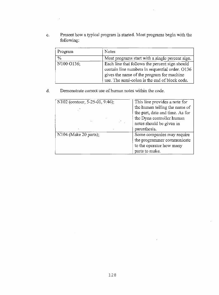
c. Present how a typical program is started. Most programs begin with the following:
Program Notes% Most programs start with a single percent sign.N100 0136; Each line that follows the percent sign should
contain line numbers in sequential order. 0136 gives the name of the program for machine use. The semi-colon is the end of block code.
d. Demonstrate correct use of human notes within the code.
N102 (contour, 5-25-01, 9:46); This line provides a note for the human telling the name of the part, date and time. As for the Dyna controller human notes should be given in parenthesis.
N104 (Make 20 parts); Some companies may require the programmer communicate to the operator how many parts to make.
128
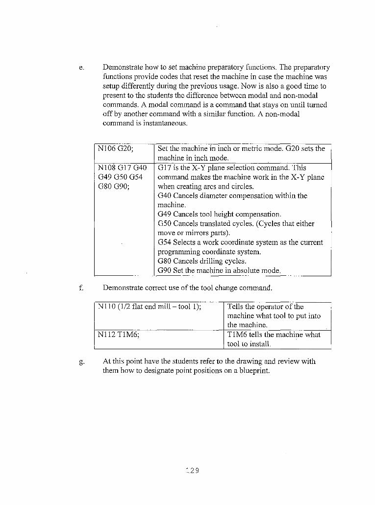
e. Demonstrate how to set machine preparatory functions. The preparatory functions provide codes that reset the machine in case the machine was setup differently during the previous usage. Now is also a good time to present to the students the difference between modal and non-modal commands. A modal command is a command that stays on until turned off by another command with a similar function. A non-modal command is instantaneous.
N106 G20; Set the machine in inch or metric mode. G20 sets the machine in inch mode.
N108 G17G40 G49 G50 G54 G80 G90;
G17 is the X-Y plane selection command. This command makes the machine work in the X-Y plane when creating arcs and circles.G40 Cancels diameter compensation within the machine.G49 Cancels tool height compensation.G50 Cancels translated cycles. (Cycles that either move or mirrors parts).G54 Selects a work coordinate system as the current programming coordinate system.G80 Cancels drilling cycles.G90 Set the machine in absolute mode.
f. Demonstrate correct use of the tool change command.
N110 (1/2 flat end mill - tool 1); Tells the operator of the machine what tool to put into the machine.
N112T1M6; T1M6 tells the machine what tool to install.
g. At this point have the students refer to the drawing and review with them how to designate point positions on a blueprint.
129

h. Next, give the first machine movement in order to move to the point position for starting the cut. Also demonstrate the difference between rapid movements (GO) and feedrate movements (Gl).
N114G0 XO. YO.; Makes the machine move rapidly to 0,0 or the origin of the part. Keep in mind that the cutter is still above the part.
i. Demonstrate the correct use of cutter height compensation commands.
N116G43 Hl; Forces the machine to look at its tool table for the height of tool number one.
j. Show the students how to turn on the spindle and coolant using m- codes and move the machine to positive . 1 inches above the part.
Nil8 M3 M8 S2800; M3 Turns on spindle in the forward direction at a spindle speed of 2800 RPM.
N120 Z.l; Rapidly moves the tool. 1 inches above the part.
k. Move the cutter down slowly at a feedrate of 6 inches per minute into the part to start cutting the part.
N122 Gl Z-.25 F6.; Move the tool -.25 deep at a feedrate and 6 inches per minute.
1. Show the students how to make the next two cuts at feedrate.
N124 Y2. F12.; Move the tool 2 inches forward.
N126X1.; Move the tool to the left until it gets to the beginning of the arc.
m. At this point the students should complete the next assignment about how to create an arc within a tool path. Come back to this lesson after presenting the circular interpolation lesson.
130

n. As detailed in the circular interpolation lesson an arc is made using either the G2 command or the G3 command depending on the arcs direction. G2 command creates a clockwise arc or circle and the G3 command creates a counter-clockwise arc or circle. In the case of this part the arc will be created using the G3 command.
N'128 G3 X2. Y1.R1.; The G3 command requires the end point of the arc (X2. Yl.) and the radius of the arc R1.
o. Finish the first contour by performing the last two cuts.
N130G1Y0.; Move the tool backwards toYO.
N132X0. Move the tool the origin of the part.
p. Move down another % inch and perform the contour again to finish the first two cuts of the part.
N134 Z-.5F6.; Move the tool down to -.5 in the Z direction.
N136 Y2. F12.N138X1.;N140 G3X2. Y1.R1.;N142 G1 YO.;N144 XO.;N146 G0Z1.; Moves the tool up 1 inch above
the part.N148 M5 M9; Turns off spindle and coolant.N150M30; Indicates program end.% The program should end with
two percent signs.%
131

Absolute Programming Lesson: Student Handouts
CNCManual Programming
By Paul A. Van Hulle & Wayne Sutter
Absolute Programming
When you have finished this assignment please have your instructor sign this sheet
in your signoff workbook.
Student Name:
Instructor’s signature
Competency achieved Yes or No:______
132

Absolute Programming
During this assignment you will be writing a CNC Program using absolute programming methods. The drawing provided (on the next page) includes all necessary instructions and dimensions.
Please submit your finished code as (1) printed copy, Remember the helpful steps of generating the setup codes first and then creating a geometry table giving the coordinates of each point required to create the desired program. Identify each point using a, b, c, d,... as necessary and then determine the desired direction and path and create the necessary code.
133
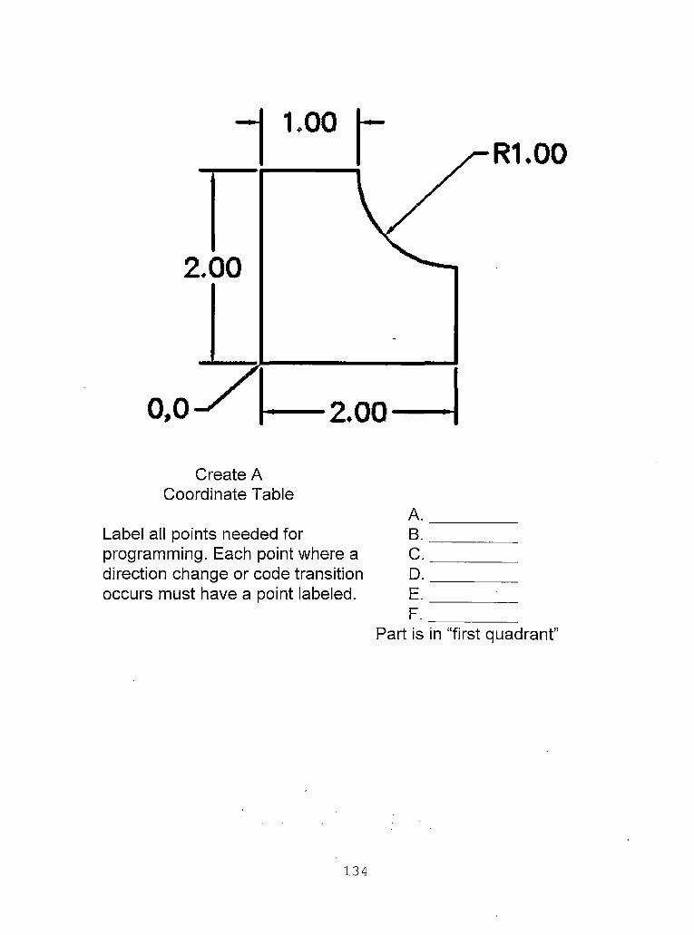
R1.00
Create ACoordinate Table
A.Label all points needed for B.programming. Each point where a Cdirection change or code transition Doccurs must have a point labeled. E.
F.Part is in “first quadrant”
134

R1.00
CNCAbsolute programming
Without CAM software, write a CNC program using a 1/2” 2 flute flat end mill. Perform 2 depth cuts of >2 depth. Machine the material as if it were aluminum 6061 alloy. You will need to apply feed and speed concepts as instructed.
Do not compensate for tool diameter. Program for center of toolto travel on the contour and profile.
Name the file “1” followed by your first initial and last name.
Example “1jsmith.xls”
135
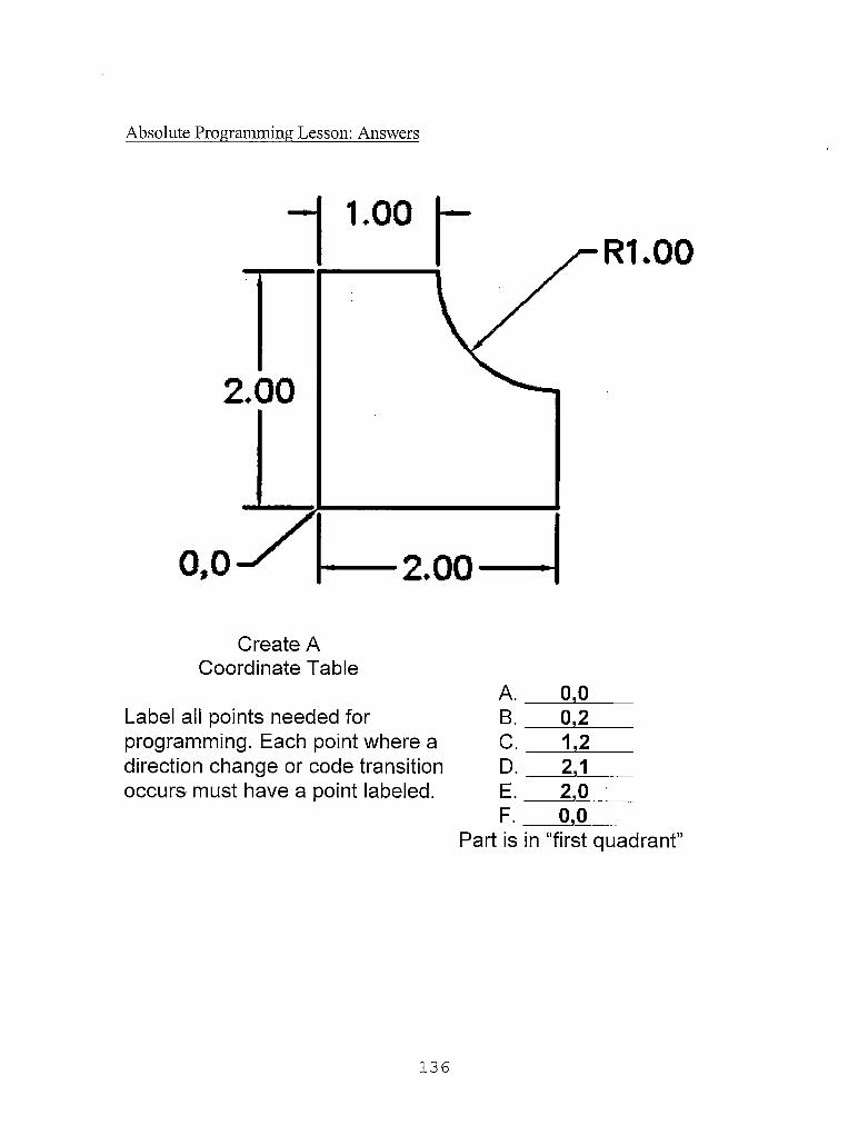
Absolute Programming Lesson: Answers
Create A Coordinate Table
Label all points needed for programming. Each point where a direction change or code transition occurs must have a point labeled.
A. 0,0B. 0,2C. 1,2D. 2,1E. 2,0F. 0,0
Part is in “first quadrant”
136
CIRCULAR INTERPOLATION FOR MILLING IN THE X-Y AXIS
Overview
Grade Level: College
Time: Two Hours
Subjects: Math, Geometry
Objectives:
At the conclusion of these activities the student will be able to
•
•
•
•
Introduction
Specify g-codes for programming circles for contours and
pockets.
Describe the difference between G02 (Clockwise) and G03
(counter-clockwise).
Demonstrate use of Radius or R’s for specifying circle
coordinates and dimensions.
Demonstrate use of circular interpolation on the CNC machine
using Manual data input.
CIRCULAR INTERPOLATION is the ability for any two axes of either a
CNC milling machine or lathe to work together in generating a programmed arc of any
degree up to 360 degrees.
137

Handbook Resources and Content Validation
When creating a contour understanding how to make a milling machine move
circularly is vital to understand how to program a machine. Many textbooks dedicate a
section to teaching how to make the machine move circularly. The following
textbooks contain a section on circular interpolation:
• CNC machining handbook (Madison, 1996, p. 128-136).• CNC mill master (Ward, 1995, p. 12-17).• Computer numerical control: Operation and programming (2nd
ed.) (Curran, 2001, p. 45-48, 253-260).• Machinery’s handbook (Oberg, 2000, p. 1254-1256).• Programming of CNC machines (2nd ed.) (Evans, 2001, p.
104-108,214-222).
Standards
WORKPLACE STANDARDSComputer Aided Manufacturing and Advanced Computer Numerical Control Technical Workplace Competencies
C. Apply Mathematical Concepts10.0 Apply Cartesian coordinate system to machining.
E. Program CNC machines and EDM2.0 Identify and describe machine operation nomenclature.3.0 Identify and describe essentials of CNC systems 4.0 Identify and describe types of CNC hardware and software5.0 Identify and describe machine axes and coordinate systems.6.0 Describe and interpret CNC coding systems7.0 Write NC programs8.0 Plan process forNC operations
(Machine tool advanced skills, 1996, p. 21-22)
138

Secretary’s Commission on Achieving Necessary Skills Course Competencies. (SCANS)
Systems: Understands complex inter-relationshipsA. Understands Systems - knows how social, organizational, and technological systems work and operates effectively with them.
Technology: Works with a variety of technologiesB. Applies Technology to Tasks - understands overall intent and proper procedures for setup and operation of equipment.
(What work requires of schools, 1991, p. 12)
CALIFORNIA CONTENT STANDARDS
MATHEMATICS Grades 8-12 Geometry
1.0 Students demonstrate understanding by identifying and giving examples of undefined terms, axioms, theorems, and reasoning (Mathematics content standards for California public schools, 1997, p. 51).
Lesson: Teacher Section
It is suggested that the teacher present the topic of Circular interpolation using
the following steps:
a. It is suggested that the topic of circular interpolation be presented after the students start the first hand programming assignment. The first hand programming assignment requires the students to define a contour with one arc.
b. When presenting the topic of circular interpolation the teacher should first instruct the students on the difference between clockwise (G2) and counter-clockwise (G3) arcs.
c. The teacher should next present what it means for the arc to end at a certain point. The arc command requires the programmer to specify the endpoint of the arc.
d. Next, the teacher should now explain how to find a radius on the drawing and how to specify that radius within the G2 or G3 command.
e. Students should now be given many examples through guided practice.
139

Circular Interpolation Lesson: Student Handouts
CNCManual Programming
By Paul A. Van Hulle
Circular Interpolation
When you have finished this assignment please have your instructor sign this sheet
in your signoff workbook.
Student Name:
Instructor’s signature
Competency achieved Yes or No:______
140

Circular Interpolation for Milling in the X-Y axis
CIRCULAR INTERPOLATION is the ability for any two axes of either a CNC milling machine or lathe to work together in generating a programmed arc of any degree up to 360 degrees.
Every block of X-Y CIRCULAR INTERPOLATION must contain the following:
#1. The arc is to be cut in what direction?G2 (Clockwise direction)
or G3 (Counterclockwise direction)
141
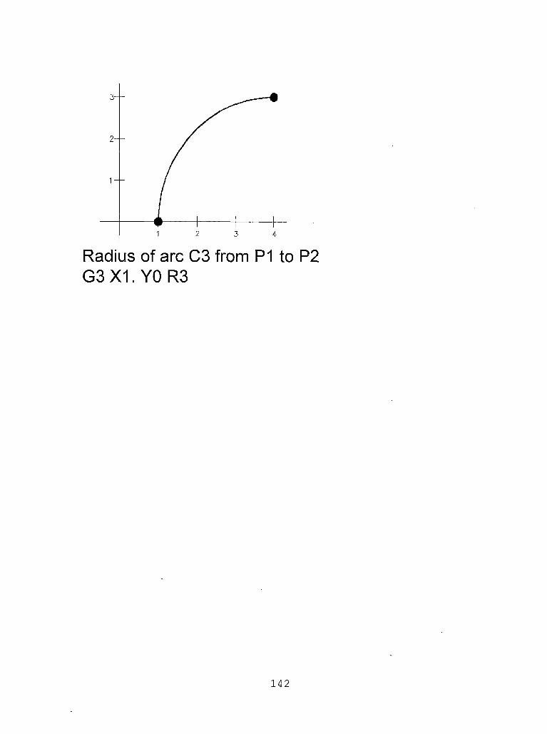
G3 X1. YO R3
142

Circular Interpolation Lesson: Answers
90 Degree Arcs Using R’s.
Write the correct NC block for each of the following arcs. G90 is in effect. Use R’s, not I’s and J’s.
143

45 Degree Arcs Using R’s.
Write the correct NC block for each of the following arcs. G90 is in effect. Use R’s, not I’s and J’s.
144

90 Degree Arcs using R’s. Answers
Write the correct NC block for each of the following arcs. G90 is in effect. Use R’s, not I’s and J’s.
145

45 Degree Arcs . Using R’s.
AnswersWrite the correct NC block for each of the following arcs. G90 is in effect.
Use R’s, not I’s and J’s
146

Special thanks to D. Ward from the Rands corporation for providing the idea
for the assignment for 90 degree arcs using R’s and 45 degree arcs using R’s. (Ward,
1995).
147
REFERENCES FOR HANDBOOK
Basic CNC operation [Training Workbook]. (1994).Minneapolis, MN: Anoka-Hennepin Technical Coll. (ERIC Document Reproduction Service No. ED391901)
Curran, K., & Stenerson, J. (2001) . Computer numerical control: operation and programming (2nd ed.). Columbus, OH: Prentice Hall.
Dyna 4M machine control and program manual Version 2.2. (n.d.). Santa Clara, CA: Dyna Mechtronics Inc.
Evans, K., Polywka, J., & Gabrel, S. (2001) . Programmingof CNC machines (2nd ed.). New York: Industrial Press Inc.
Gibbs, D. (1991). An introduction to CNC machining and programming,. New York: Industrial Press Inc.
Krar, S., Gill, A., & Smid, P. (2001). Computer numerical control simplified. New York: Industrial Press Inc.
Lin, S. J., & Shiue, T. (1998) . Mastercam version 7. Ann Arbor, MI: Scholars International Publishing Corp.
Mastercam Handbook, Volume 1. (2001). Poway, CA: San DiegoCAD/CAM.
Machine tool advanced skills (MAST). (1996). Waco, TX:Taxas State Technical College. (ERIC Document Reproduction Service No. ED401441)
Madison, J. (1996). CNC machining handbook. New York: Industrial Press inc.
Mathematics content standards for California publicschools. Kindergarten though grade twelve. (1997). Sacramento, CA: California Department of Education. Retrieved November 25, 2001 from,http://www.cde.ca.gov/board/pdf/math.pdf
Mathematics framework for California public schools. Kindergarten through grade twelve. (2000).Sacramento, CA: California Department of Education. Retrieved November 25, 2001 from,http://www.cde.ca.gov/cdepress/math.pdf
148

Oberg, E., Jones, F. D., Horton, H., & Ryffell, H. H.(2000). 26th edition machinery's handbook. New York: Industrial Press Inc.
Sherwood Media. Math for part programmers.
What work requires of schools - A SCANS report for America 2000. (1991) . The Secretary's Commission' on AchievingNecessary Skills. U.S. Department of Labor. Retrieved November 6, 2001 from, http://wdr.doleta.gov/SCANS/ whatwork/whatwork.html
149

REFERENCES
Blanchard, A. (2000a). Contextual teaching and learning. Retrived November 3, 2001 from,http://www.horizonshelpr.org/contextual/contextual.htm
Blanchard, A. (2000b). Horizons Electronic Lesson Plan Resource. Retrived November 20, 2001 from, http://www.horizonshelpr.org/home/home.html
Bolles, R. N. (1994). The 1994 what color is your parachute. Berkeley, CA: Ten Speed Press.
California employment development department - Labor market information, Machinists. (2000). RetrivedOctober 30, 2001 from, http://www.calmis.cahwnet.gov/ file/occup$/DCLAW2000/Machinists-ws2000.htm
California employment development department - Labormarket information, Numerical-Control machine-tool operators & tenders-Metal & plastic. (2000). RetrivedOctober 30, 2001 from, http://www.calmis.cahwnet.gov/ file/occup$/DCLAW2 000/NetworkControl-ws2000.htm
Curran, K., & Stenerson, J. (2001). Computer numerical control: operation and programming (2nd ed.). Columbus, OH: Prentice Hall.
County of San Bernardino - 1999 Occupational outlook report. (1999). San Bernardino CA: Workforce Investment Board of San Bernardino County. Retrived October 30, 2001 from, http://www.calmis.calwnet.gov/ htmlfile/ccois/199900R/SanBernardino99.pdf
Evans, K., Polywka, J., & Gabrel, S. (2001). Programmingof CNC machines (2nd ed.). New York: Industrial Press Inc.
Ward, D. B. (1995). CNC mill master. Santa Clara, CA:Rands System, Inc.
Hutcheson, P. (1999). Educating a globally productive citizenry: the role of higher educaiton in the integration of learning and work. A monograph for college leaders. Boston, MA: National Commission for Cooperative Education. (ERIC Document Reproduction Service No. ED428609)
150

Illinois occupational skill standards: machining skills cluster. (1997). Macomb II: Illinois Occupational Skill Standards and Credentialing Council,Carbondale. (ERIC Document Reproduction Service No. ED443027)
Kibbe, R. R., Neely, J. E., Meyer, R. 0., & White, W. T.(2002). Machine tool practices, (7th, ed.) . Columbus, OH: Prentice Hall.
Krar, S., Gill, A., & Smid, P. (2001). Computer numerical control simplified. New York: Industrial Press Inc.
Landmarks in digital computer - 1945 ENIAC. (1995). NMAH Collections. Obtained October 25, 2001 from, http://www.nasm.edu/nasm/dsh/LDC/ldc_part4.html
Lankard, B. A., (1992). Integrating academic andvoactional education: strategies for implementation. (ERIC Document Reproduction Service No. ED346317)
Lin, S. J., & Shiue, T. (1998) . Mastercam version 7. Ann Arbor, MI: Scholars International Publishing Corp.
Labor market information study. (1999) . Riverside CA: Riverside County Workforce Development Board.Retrived October 30, 2001 from,http://www.calmis.calwnet.gov/htmlfile/ccois/1999OOR/ Riverside99.pdf
Machine tool advanced skills (MAST) . (1996) . Waco, TX:Taxas State Technical College. (ERIC Document Reproduction Service No. ED401441)
Machining skills level 1. (1997). National Institute forMetalworking Skills, Inc. (NIMS). Retrived November 20, 2001 from, http://www.nims-skills.org/pages/ standards.htm
McAlonan, S., Hotchkiss, H., & Urich, L., Bringingstandards to life. A "how to" guide to contextual learning and curriculum integration. (ERIC Document Reproduction Service No. ED434885)
151

Milne, A. M. (1998). Educational reform and vocational education. Washington DC: National Assessment of Vocational Education. (ERIC Document Reproduction Service No. ED421659)
Minimum wage laws in the states. (2001). United StatesDepartment of Labor. Retrived October 31, 2001 from, http://www.dol.gov/dol/esa/public/minwage/america.htm
Numerical Control machine operators. - CaliforniaOccupational guide number 548. (1998) . State ofCalifornia, Employment Development Department, Labor Market Information Division. Retrived November 10, 2001 from, http://158.96.231.221/calmis/file/ occguide/numcont.htm
Oberg, E., Jones, F. D., Horton, H., & Ryffell, H. H.(2000) . 26th edition machinery's handbook. New York: Industrial Press Inc.
Occupational Outlook Handbook, 2000-01 Edition. (2001) .U.S. Department of Labor. Http://www.bis.gov/oco/ home.html
Occupational outlook Los Angeles - A labor marketinformation study. (1998). Long Beach CA: The City of Long Beach Economic Development Bureau. Retrived October 30, 2001 from, http://www.calmis.cahwnet.gov/ htmlfile/ccois/LosAngeles98.pdf
Occupational outlook Los Angeles - A labor marketinformation study. (1999). Long Beach CA: The City of Long Beach Economic Development Bureau. Retrived October 30, 2001 from, http://www.calmis.cahwnet.gov/ htmlfile/ccois/199900R/LosAngeles99.pdf
Orange County 2000 occupational outlook. (2000). OrangeCA: Orange County Workforce Investment Boards. Retrived October 30, 2001 from,http://www.calmis.calwnet.gov/htmlfile/ccois/200000R/ OrangeOO.pdf
Repp, V., & McCarthy, W. (1984). Machine tool technology. Peoria, II: Glencoe/McGraw-Hill.
152
San Diego County 2001 occupational outlook report. (2001) . San Diego CA: The San Diego Workforce Partnership, Inc. Retrived October 30, 2001 from,http://www.calmis.calwnet.gov/htmlfile/ccois/200000R/ SanDiego00.pdf
Scarcella, J.. (2001) . San Bernardino CA: Cal State San Bernardino. Retrived November 10, 2001 from, http://www.etext.net/etexts/Sca637/quiz_l.html
Skilled occupations in robotics/automated systems.California Occupational Guide Number 2004-D. (1994).State of California, Employment DevelopmentDepartment, Labor Market Information Division, Information Services Group. Retrived November 2, 2001 from, http://158.96.231.221/calmis/file/occguide/ robotics.htm
Volti, R. (1992). Society & technological change(2nd ed.). New York: St. Martin's Press, Inc.
Walker, J. R. (2000). Machining fundamentals. From basic to advanced techniques. Tinely Park, II: The Goodheart-Wilcox Company, Inc.
War Department. Bureau of public relations, Press branch. (1946). Retrived November 10, 2001 from, http://americanhistory.si.edu/csr/comphist/prl.pdf
Ward, D. B. (1995). CNC mill master. Santa Clara, CA:Rands System, Inc.
What work requires of schools - A SCANS report for America 2000. (1991). The Secretary's Commission on AchievingNecessary Skills. U.S. Department of Labor. Retreived November 6, 2001 from, http ://wdr . doleta. gov/SCANS/ whatwork/whatwork.html
Wright, T. (1996). Technology systems. South Holland, IL: The Goodheart-Willcox Company, Inc.
Zargari, A. (1997). Vocational-technical education's role in welfare reform: Providing employability skills for welfare recipients [Electronic version]. Journal of Industrial Teacher Education, 34(3).
153