Embed Size (px)
Citation preview
AN EFFICIENCY METER FOR ELECTRIC INCANDESCENTLAMPS.
By Edward P. Hyde and H. B. Brooks.
1. INTRODUCTION.
The life of a normal incandescent lamp depends primarily on the
temperature at which the lamp is operated, and the temperature of
the filament is a function, not of the watts or of the candlepower
simply, but of the ratio, watts per candle; that is, of the so-called
efficiency1at which the lamp is operated. For lamps of the same
type, the higher the efficiency the shorter the life, and vice versa;
and since uniformity in life is one of the first qualifications of a good
lot of lamps, uniformity in efficiency is of great importance.
There is at present no direct reading ''efficiency meter" on the
market, so far as the writers know, and it may be that this is partly
the reason for the present custom of specifying limits of watts and
candlepower, and not limits of efficiency. In order to meet the
need for an efficiency meter in the photometric work of the Bureau
of Standards, the writers have recently designed and constructed
such an instrument, the theory and operation of which will be
described in this paper.
1 In the following paper the term '
' efficiency '
' will be used to designate the watts
per mean horizontal candle, in accordance with the more common use of the term in
industrial practice. The proper definition of the word '
' efficiency '
' would be lumens
per watt, which gives a much more significant constant for a radiating source than
watts per mean horizontal candle. For incandescent lamps of the same type, how-ever, in which the ratio of mean spherical to mean horizontal intensity is approxi-
mately constant for different lamps, the watts per mean horizontal candle gives an
approximate idea of the relative temperatures of the filaments. Moreover, all that
is said here in regard to watts per mean horizontal candle would apply equally well
to watts per mean spherical candle, if the photometer gave readings of mean spher-
ical instead of mean horizontal intensity, and by adding a new scale to the wattmeter
direct readings in lumens per watt could be made.
145
146 Bulletin of the Bureau ofStandards. [Vol. 2, No. 1.
The problem to be solved consisted in devising some method by
which the readings of a wattmeter would be made to vary inversely
as the candlepower. Two general methods suggested themselves,
a mechanical method and an electrical one. According to the
former either the scale of the wattmeter would be moved by the
motion of the photometer carriage, or the motion of the latter
would vary the counterforce opposed to the moving coil, as, for
example, by increasing or decreasing the effective length of the
spring. Either of these methods would require the wattmeter to
be specially constructed, and to be fixed in position relative to the
photometer, and would present other serious practical difficulties,
so that the mechanical method was abandoned for the more promis-
ing electrical method.
According to the latter there are three possible ways of decreas-
ing- the wattmeter reading: in the ratio of -=—^: (a) bv
Candlepower v 7 J
placing a variable resistance in parallel with the current coil of the
wattmeter; (b) by placing a variable resistance in parallel with the
moving coil ; and (c) by placing a variable resistance in series with
the pressure circuit in the wattmeter. Before discussing these
methods it should be pointed out that in every case this variable
resistance must be controlled by the motion of the photometer, as
by the use of a sliding contact moving over a coil, so that for all
positions of the photometer the reading of the instrument shall be
~ . WattsConstant X ~ r,Candlepower
where the candlepower is given by the index on the photometer
carriage. If we should make the constant equal to unity the read-
ing on the instrument would be so small compared with the full
scale deflection that only a relatively low accuracy could be obtained,
so that it seemed desirable to make the constant 10, since then the
reading would come at a good point on the scale and at the same
time the scale reading would give the true watts per candle by
moving the decimal point. To take an example, suppose that a
16-cp lamp requires 64 watts at normal voltage. In order to makethe instrument read watts per candle directly we must so alter the
resistance of the instrument by one of the above methods, or by
*g^-ks
~\ Efficiency Meterfor Incandescent Lamps. 147
some combination of them, that the instrument shall indicate 1 16
of its original reading; that is, 64 '16= 4. If, however, instead of
reducing the reading to 1 16 we reduce it to 10 16 of its original
value, it will now give a reading of 10 16x64= 40, which will be
ten times the watts per candle, but which will come at a much more
desirable part of the scale of the instrument. At 10 cp the instru-
ment will read 10/10 X watts, or watts directly, at 20 cp 10 20 X watts
or one-half the watts, and so on for other candlepower values.
To return to the three electrical methods suggested for the reduc-
tion of the wattmeter reading, case (a) is objectionable because of
the low resistance of the series coil in a wattmeter of the required
range. It would necessitate a low resistance in the shunt circuit
controlled by the moving screen, and hence would be liable to error
due to variations in the contact resistance. In case (b) this objec-
tion will not arise, since the resistance of the moving coil will be
about 50 ohms, and hence the shunt controlled by the movement of
the screen will not, in general, be less than 50 ohms, in comparison
with which variations in the resistance of well made sliding contacts
will be negligible. This method requires that an extra lead be
brought out to an extra binding post on the wattmeter, as both
terminals of the moving coil are not directly accessible.
In both the shunt methods the range of the efficiency meter, in
case the instrument is to read 10 times the efficiency, will have as
its lower limit 10 cp, for at 10 cp the resistance of the external shunt
must be infinite, or, in other words, the shunt circuit must be open.
Moreover, in case (b) if the instrument is to be used for candle-power
values above 20 cp the shunt resistance would become smaller than
50 ohms, and hence care must be exercised to have the contact
resistance sufficiently constant to produce no appreciable error. In
general practice, however, in reading 1 6-cp lamps the range is seldom
greater than from 10 to 20 cp, so that these difficulties are not serious.
Method (c) is more nearly free from errors and limitations than
either of the other two methods. iVccording to this method a varia-
ble resistance is placed in series with the pressure circuit in the watt-
meter, and since the latter will have a resistance of several thousand
ohms, the contact resistance is of much less importance than in the
other cases. Moreover there are practically no limits to the range
of the instrument, if we take out of the wattmeter part of the resist-

148 Bulletin of the Bureau ofStandards. [Vol. 2, jvo. 1.
ance in series with the moving coil. This becomes necessary only
in case we desire to use the efficiency meter below 10 cp; otherwise
the wattmeter can be used without any modification. Method (c)
therefore seemed more promising than either of the other two
methods, and was hence adopted.
2. THEORY OF METHOD.
Assuming that the wattmeter to be used reads correctly as a watt-
meter, the resistance in series with it should be zero at 10 cp, since
the reading at 10 cp should be total watts. At 20 cp the reading
should be one-half the total watts; that is, the added resistance for
the position of the photometer corresponding to 20 cp should equal
the resistance of the wattmeter. It only remains, therefore, to deter-
mine the relation between the candle-power reading and the resist-
ance for other points on the bar, and to find some convenient practi-
cal way of introducing the additional resistance.
Let 2a be the distance (supposed to be constant) between the two
lamps, Ixthe intensity of the comparison lamp, / the intensity of
the test lamp, and x the distance from the test lamp to the photo-
meter screen when in a position of balance. Then by the inverse
square law,
/=/* (^b) «
Moreover, if W is the total watts supplied to the lamp, and E the
efficiency or watts per candle,
WE=T (2)
and if ,5 denote the scale reading of the instrument when the exter-
nal resistance r is in series with the wattmeter pressure winding of
resistance rX)and K the factor of proportionality between the scale
reading and the efficiency, we get
S=—J- W=KE=K^ (3)
or

Brooks~\ Efficiency Meter for Incandescent Lamps. 149
from which
r= r»(?- 1
)(5)
Substituting for / its value as given in equation (1),
-#(i^y- x
](6
)r=r.
which gives the resistance r, which must be added to the resistance
rxfor any position x on the bar.
The method which seemed most desirable for the construction of
a rheostat to follow this law consisted in winding closely a fine silk-
covered resistance wire on a
EMW\H\J
block of insulating material.
After coating with shellac var-
nish and drying, the insulation
was removed along a strip over
which travels a contact brush
attached to the photometer car-
riage. The variable rheostat
thus formed is connected in the
pressure circuit of the wattmeter,
so that the resistance of this cir-
cuit varies with the position of
the photometer. The electrical
connections are shown diagram-
matically in Fig. 1. The top of the block, along which the contact
is made, is straight, and the bottom of the block must have what-
ever form is necessary to give the proper increments dr to the
resistance as the contact moves over successive small distances dx.
By differentiating equation (6) with respect to x we get the equation,
Diagram of Connections.
dr_ \arxI
xx
dx K (2a-xJ (7)
If we let h be the thickness of the block, y the height of the block
at any point—that is, the ordinate of the curve measured downward
—
p the specific resistance of the wire, 2b the diameter of the bare wire,
150 Bulletin of the Bureau ofStandards. [voi. 2,No.i.
and 11 the number of turns of the covered wire per unit distance on
the block, then the resistance dr contained in a small distance dx is
dr=<ypp^ ndx (8)
or
£=>+*> (9)
drEquating this value of -j- to that obtained in equation (7)
^+*)=^7^ Mfrom which
irbJ K (2a—xf
2irab%r1L x 7 , .
-y=^f^(2^)^' (")
which relation determines the form of the bottom of the block. In
this equation a, rv Ix , K, and h may be taken as constants, while b,
n, and p depend on the wire that is used. We may introduce the
resistance per unit length, pv instead of the specific resistance p y
using the relation
*=^Combining this with equation (11) we get the more convenient form
2arxL x . f v
J Knp! (2a— x)3 '
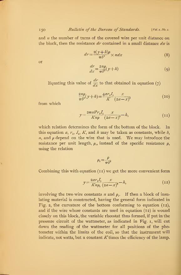
involving the two wire constants n and jOr If then a block of insu-
lating material is constructed, having the general form indicated in
Fig. 2, the curvature of the bottom conforming to equation (12),
and if the wire whose constants are used in equation (12) is woundclosely on this block, the variable rheostat thus formed, if put in the
pressure circuit of the wattmeter, as indicated in Fig. 1, will cut
down the reading of the wattmeter for all positions of the pho-
tometer within the limits of the coil, so that the instrument will
indicate, not watts, but a constantK times the efficiency of the lamp.

Brooks^] Efficiency Meterfor Incandescent Lamps. 151
3. CONSTRUCTION OF INSTRUMENT.
It has been shown that it is desirable to give the constant K the
value 10, since then the wattmeter reads watts per candle directly,
by moving the decimal point. We will assume that the apparatus
is to be designed for 16-cp lamps. In adjusting a photometer for
the measurement of 16-cp lamps the voltage on the comparison
lamp is adjusted until the reading on a 16-cp standard lamp placed
in the test-lamp socket comes at 16 cp, the middle point on the bar.
Then the intensity of the comparison lamp, Ix , is 16 cp. The dis-
tance between the two lamps in commercial photometry is always
constant and equal to some standard length, such as 100 or 200
inches, or 250 cm. Hence a, which is one-half this distance, is the
constant distance from either lamp to the center of the bar. In the
commercial photometer at the Bureau of Standards a— 125 cm. AWeston wattmeter was used having a resistance of 2,630 ohms. Theother constants entering into equation (12) are h
)the thickness of
the block, which was made 1 cm, and the two wire constants n and pv
In designing the resistance block it is necessary to work both ways
from equation (12). First having decided what the approximate
dimensions of the block shall be, put in equation (12) the value of yfor some value of x, preferably that corresponding to 20 cp, and
from this equation determine the product npx
. Then select some
wire having approximately this value of npx ,put the exact values,
as obtained from measurements of a sample of the wire, back into
equation (12), and plot the desired curve.
It may be well to say a word at this point in regard to the limits
of the efficiency meter in practice. As stated, if we make K— 10
there will be no resistance in series with the wattmeter when the
photometer is at 10 cp. Hence the coil begins at this point unless
it is desired to read efficiencies for points below 10 cp, in which case
some of the resistance in series with the moving coil can be taken
out of the wattmeter and placed in the external coil. This can be
accomplished without unfitting the wattmeter for other uses, by
bringing to an extra binding post on the instrument a tap from some
point in the resistance depending on how far below 10 cp the meter
is to be used. While there is no difficulty in doing this, there is
also no need generally of having the meter read below 10 cp on a 16
152 Bulletin ofthe Bureau ofStandards. [Vol. 2, No. 1.
cp bench. The upper limit can be as high as desired, although the
ordinates of the block increase very rapidly as we reach higher
candle-power positions, so that unless there is some particular reason
to the contrary it will be found desirable to take as the upper limit
20 or 25 cp. The meter at the Bureau reads watts per candle for a
range of from 10 to 20 cp.
We have spoken thus far of a single block wound with wire; wehave found it very desirable, however, to have two blocks instead of
one. First, for any wire large enough for mechanical strength the
slope of the curve at 20 cp is so great that it not only makes an awk-
ward-looking device, but also introduces difficulties in the winding.
By using two blocks side by side, equal in every way, the curvature
of each is much less than that of the single block. Secondly, with
the single block the sliding contact that moves with the photometer
must carry with it a flexible wire, which is objectionable. If two
blocks are used, however, the photometer merely carries a brush
which spans the gap between the two coils. In this arrangement
the ends of the wire at the 20-cp point are joined together, keeping
the wattmeter circuit closed in case the contact between the brush
and the coil should be momentarily broken.
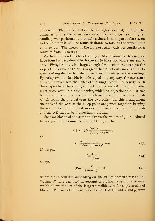
For two blocks of the same thickness the values of y-\-h deduced
from equation (12) must be divided by 2, so that
, 7 t2ar, I. x
or
If we put
we get
Knpx (2a— x)
3
y=a*)
Ix,
Xx 3-h (13)* Knp
x(2a— xf
v 0J
C=^Ii (14)
>= c (^*f-k w
where C is a constant depending on the values chosen for n and px.
" Climax" wire was used on account of its high specific resistance,
which allows the use of the largest possible wire for a given size of
block. The size of the wire was No. 30 B. & S., and n and pxwere
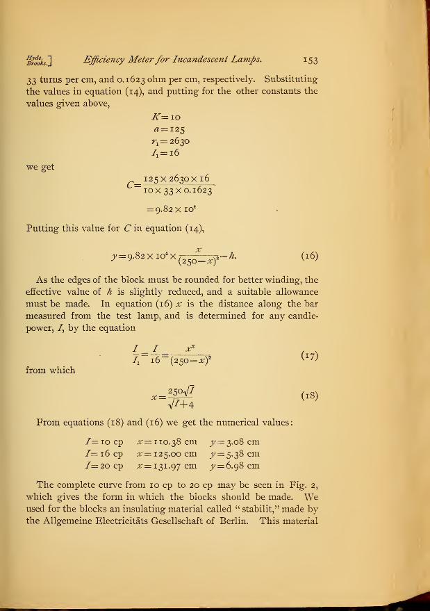
Brooks ] Efficiency Meterfor Incandescent Lamps. 153
$$ turns per cm, and 0.1623 ohm per cm, respectively. Substituting
the values in equation (14), and putting for the other constants the
values given above,
iT=io^=125r
x= 2630
71= i6
we get
125X 2630X 16—10x33x0.1623
= 9.82X io4
Putting this value for C in equation (14),
y= 9.82Xio>x{25
*_xy -k. (16)
As the edges of the block must be rounded for better winding, the
effective value of h is slightly reduced, and a suitable allowance
must be made. In equation (16) x is the distance along the bar
measured from the test lamp, and is determined for any candle-
power, 7, by the equation
I, i6~{2So-xf ^from which
^^ (18)
From equations (18) and (16) we get the numerical values:
7=iocp ^=110.38 cm y = 3.08 cm7=i6cp x— 125.00 cm y — 5.38 cm7=20 cp ^=131.97 cm y= 6.g8 cm
The complete curve from 10 cp to 20 cp may be seen in Fig. 2,
which gives the form in which the blocks should be made. Weused for the blocks an insulating material called " stabilit," made by
the Allgemeine Electricitats Gesellschaft of Berlin. This material
154 Bulletin of the Bureau ofStandards. [Voi.2,No.i.
is said to possess high insulation resistance combined with the ability
to resist heat and moisture. It was used in preference to fiber
because of the hygroscopic nature of the latter. Hard rubber would
no doubt answer the purpose as well as stabilit.
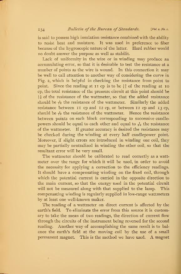
Lack of uniformity in the wire or in winding may produce an
accumulating error, so that it is desirable to test the resistance at a
number of points as the wire is wound. In this connection it maybe well to call attention to another way of considering the curve in
Fig. 2, which is helpful in checking the resistance from point to
point. Since the reading at n cp is to be {{ of the reading at 10
cp, the total resistance of the pressure circuit at this point should be
H of the resistance of the wattmeter, so that the added resistance
should be to the resistance of the wattmeter. Similarly the added
resistance between 1 1 cp and 1 2 cp, or between 1 2 cp and 1 3 cp,
should be to the resistance of the wattmeter. Hence the resistance
between points on each block corresponding to successive candle-
powers should be equal to each other and equal to £0 the resistance
of the wattmeter. If greater accuracy is desired the resistance maybe checked during the winding at every half candlepower point.
Moreover, if slight errors are introduced in winding one coil, they
may be partially neutralized in winding the other coil, so that the
resultant error will be very small.
The wattmeter should be calibrated to read correctly as a watt-
meter over the range for which it will be used, in order to avoid
the necessity for applying a correction to the efficiency readings.
It should have a compensating winding on the fixed coil, through
which the potential current is carried in the opposite direction to
the main current, so that the energy used in the potential circuit
will not be measured along with that supplied to the lamp. This
compensating winding is regularly supplied in low-range wattmeters
by at least one well-known maker.
The reading of a wattmeter on direct current is affected by the
earth's field. To eliminate the error from this source it is custom-
ary to take the mean of two readings, the direction of current flow
through the circuits of the instrument being reversed for the second
reading. Another way of accomplishing the same result is to bal-
ance the earth's field at the moving coil by the use of a small
permanent magnet. This is the method we have used. A magnet
Hyde. ~]
Brooks.J Efficiency Meterfor Incandescent Lamps. J 55
10 cm long and 1.3 cm diameter, when placed north and south at
about five or six cm under the bottom of the wattmeter case bal-
anced the earth's field almost exactly for all points of the scale that
are used (see below), the wattmeter being placed with its longer
dimension approximately north and south. Another way of elimi-
nating the effect of the earth's field is to use an astatic wattmeter.
Such instruments are not on the market in portable form, but they
can doubtless be had from instrument makers if required. If the
instrument is to be used in a location subject to strong and variable
stray fields the use of an astatic wattmeter might be necessary, but
in most cases the ordinary wattmeter with a compensating magnet
will doubtless answer all requirements.
±j
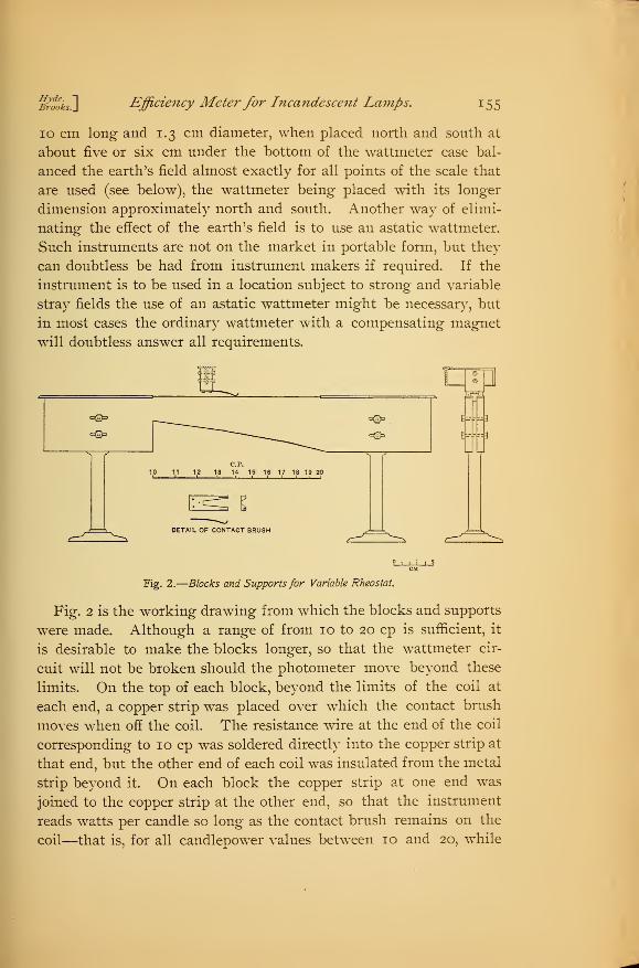
Fig. 2.
—
Blocks and Supports for Variable Rheostat.
Fig. 2 is the working drawing from which the blocks and supports
were made. Although a range of from 10 to 20 cp is sufficient, it
is desirable to make the blocks longer, so that the wattmeter cir-
cuit will not be broken should the photometer move beyond these
limits. On the top of each block, beyond the limits of the coil at
each end, a copper strip was placed over which the contact brush
moves when off the coil. The resistance wire at the end of the coil
corresponding to 10 cp was soldered directly into the copper strip at
that end, but the other end of each coil was insulated from the metal
strip beyond it. On each block the copper strip at one end was
joined to the copper strip at the other end, so that the instrument
reads watts per candle so long as the contact brush remains on the
coil—that is, for all candlepower values between 10 and 20, while
156 Bulletin ofthe Bureau ofStandards. [ Vol. 2, No. i.
beyond these limits the instrument reads watts. In order that
for any position of the photometer the watts can be read directly,
a switch is used by means of which the resistance external to the
wattmeter can be short-circuited, so that either watts or efficiency
can be read.
The blocks were mounted on stands with the tops of the coils at
a convenient distance below the photometer carriage. On the latter
was mounted a hard-rubber block carrying the phosphor bronze
contact brush which completes the circuit from one coil to the other.
The blocks were slotted to receive bolts holding them in place on
the stands. Thus a linear adjustment of each coil independently
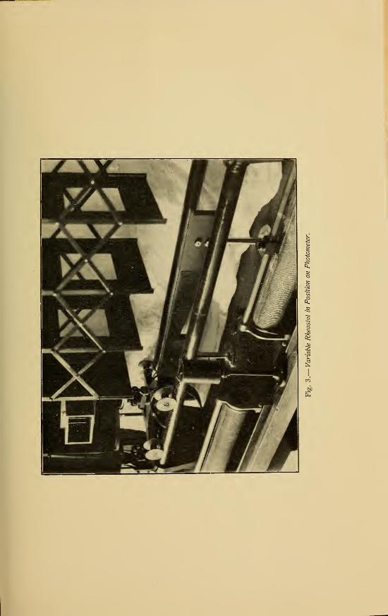
can be made, which is desirable. Fig. 3, which was made from a
photograph, shows the blocks in position on the photometer, the
wattmeter not being shown.
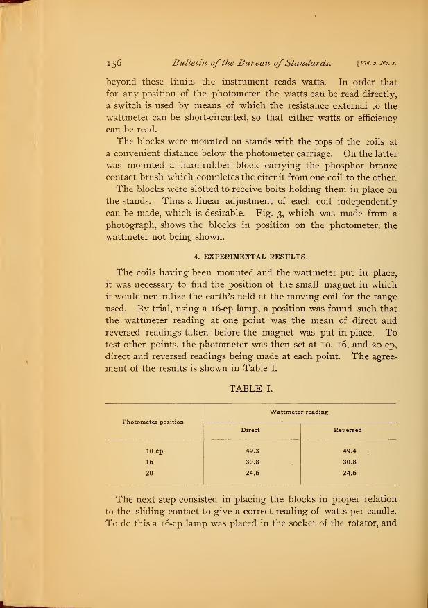
4. EXPERIMENTAL RESULTS.
The coils having been mounted and the wattmeter put in place,
it was necessary to find the position of the small magnet in which
it would neutralize the earth's field at the moving coil for the range
used. By trial, using a 16-cp lamp, a position was found such that
the wattmeter reading at one point was the mean of direct and
reversed readings taken before the magnet was put in place. Totest other points, the photometer was then set at 10, 16, and 20 cp,
direct and reversed readings being made at each point. The agree-
ment of the results is shown in Table I.
TABLE I.
Photometer position
Wattmeter reading
Direct Reversed
10 cp
16
20
49.3
30.8
24.6
49.4
30.8
24.6
The next step consisted in placing the blocks in proper relation
to the sliding contact to give a correct reading of watts per candle.
To do this a 16-cp lamp was placed in the socket of the rotator, and
Hyde.Brooks. Efficiency Meterfor Incandescent Lamps. 157
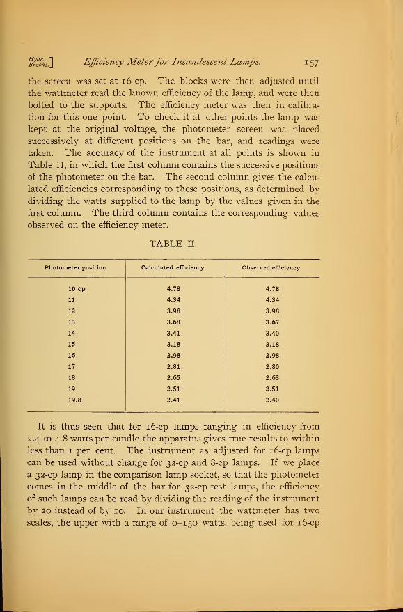
the screen was set at 16 cp. The blocks were then adjusted until
the wattmeter read the known efficiency of the lamp, and were then
bolted to the supports. The efficiency meter was then in calibra-
tion for this one point. To check it at other points the lamp was
kept at the original voltage, the photometer screen was placed
successively at different positions on the bar, and readings were
taken. The accuracy of the instrument at all points is shown in
Table II, in which the first column contains the successive positions
of the photometer on the bar. The second column gives the calcu-
lated efficiencies corresponding to these positions, as determined by
dividing the watts supplied to the lamp by the values given in the
first column. The third column contains the corresponding values
observed on the efficiency meter.
TABLE II.
Photometer position Calculated efficiency Observed efficiency
10 cp 4.78 4.78
11 4.34 4.34
12 3.98 3.98
13 3.68 3.67
14 3.41 3.40
15 3.18 3.18
16 2.98 2.98
17 2.81 2.80
18 2.65 2.63
19 2.51 2.51
19.8 2.41 2.40
It is thus seen that for 16-cp lamps ranging in efficiency from
2.4 to 4.8 watts per candle the apparatus gives true results to within
less than 1 per cent. The instrument as adjusted for 16-cp lamps
can be used without change for 32-cp and 8-cp lamps. If we place
a 32-cp lamp in the comparison lamp socket, so that the photometer
comes in the middle of the bar for 32-cp test lamps, the efficiency
of such lamps can be read by dividing the reading of the instrument
by 20 instead of by 10. In our instrument the wattmeter has two
scales, the upper with a range of 0-150 watts, being used for 16-cp
158 Bulletin of the Bureau ofStandards. [ Vol. 2, No. i.
lamps. By using the lower scale of 0-75 watts when measuring 32-
cp lamps the instrument is still direct reading. This refers only
to the reading of the deflection ; the electrical connections are the
same for 16 and for 32-cp lamps.
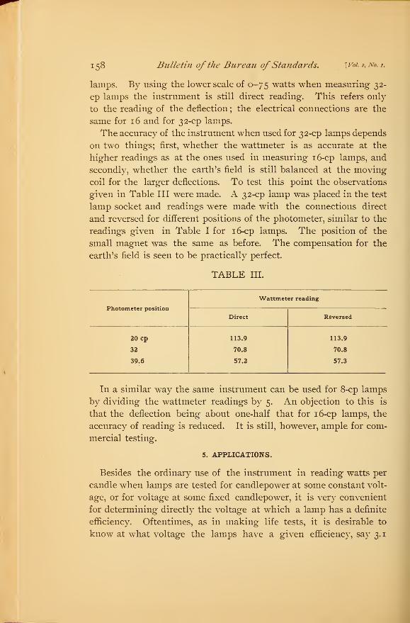
The accuracy of the instrument when used for 32-cp lamps depends
on two things; first, whether the wattmeter is as accurate at the
higher readings as at the ones used in measuring 16-cp lamps, and
secondly, whether the earth's field is still balanced at the moving
coil for the larger deflections. To test this point the observations
given in Table III were made. A 32-cp lamp was placed in the test
lamp socket and readings were made with the connections direct
and reversed for different positions of the photometer, similar to the
readings given in Table I for 16-cp lamps. The position of the
small magnet was the same as before. The compensation for the
earth's field is seen to be practically perfect.
TABLE III.
Photometer position
Wattmeter reading
Direct Reversed
20 Cp
32
39.6
113.9
70.8
57.2
113.9
70.8
57.3
In a similar way the same instrument can be used for 8-cp lamps
by dividing the wattmeter readings by 5. An objection to this is
that the deflection being about one-half that for 16-cp lamps, the
accuracy of reading is reduced. It is still, however, ample for com-
mercial testing.
5. APPLICATIONS.
Besides the ordinary use of the instrument in reading watts per
candle when lamps are tested for candlepower at some constant volt-
age, or for voltage at some fixed candlepower, it is very convenient
for determining directly the voltage at which a lamp has a definite
efficiency. Oftentimes, as in making life tests, it is desirable to
know at what voltage the lamps have a given efficiency, say 3.1
j$o*zs~\ Efficiency Meter for Incandescent Lamps. 159
watts per candle. The only way to do this at present is to estimate
the approximate voltage, and from the candlepower and wattage
readings at that voltage to calculate the voltage corresponding to the
required efficiency. This computation involves the use of the law of
variation of efficiency with voltage, and is hence both tedious and
unreliable. By the use of the efficiency meter, on the other hand, one
operator gradually raises the voltage and observes the efficiency
meter, while the other observer follows the change in candlepower
with the photometer. When the instrument indicates the proper
efficiency, the corresponding voltage is read. This method is not
only quicker, but much more accurate and satisfactory.
If the utmost accuracy is desired, certain precautions must be
taken. If the line voltage is considerably higher than the voltage
at the lamp—that is, if there is a large drop through the rheostats
—
any change in the current will cause a relatively large change in the
voltage on the lamp. Hence if the voltage at the lamp is adjusted
when the photometer carriage is at 10 cp, the voltmeter will show a
slight rise when the photometer is moved to 20 cp, due to the increase
of resistance of the pressure circuit, and the consequent decrease in
the pressure current. With the extreme travel of the carriage just
given, this rise would be a few tenths of a volt, if the drop in the
rheostats is 10 volts and 16-cp lamps are being tested. In practice,
however, there is almost never any occasion to move the photometer
over more than three or four candlepower after the voltage has been
adjusted, and moreover the effect of a motion of three or four can-
dlepower at 16 cp is not so great as at 10 cp, because of the higher
resistance in the pressure circuit. A motion of the photometer from
14 to 18 cp would cause a rise in the voltage of about one-tenth of a
volt, with 10 volts drop through the rheostats. In the second place,
the observer at the photometer would bring the screen to a position
of approximate balance immediately and the second observer could
correct for any small initial change, such initial change being rather
common for other reasons. Finally, if the line voltage is kept but
slightly above the lamp voltage, as may be done when a storage bat-
tery is used, the error becomes entirely negligible in ordinary cases.
If the tests are made on a generator circuit where the voltage is
unsteady it will usually be found desirable to use the "same circuit"
method, in which case both lamps are changed about the same by
24353—No -1—°6 :I
160 Bulletin ofthe Bureau ofStandards. Woi. z, No. /.]
the motion of the photometer, so that the error is negligible. This
is the only source of error peculiar to the efficiency meter. Theother sources of error are those which must be guarded against in
any case. For example, whether we are measuring the current on
an ammeter, the watts on a wattmeter, or the watts per candle on an
efficiency meter, we must guard against errors due to the voltmeter
current. If we read with the voltmeter in circuit we must correct
the ammeter or wattmeter reading. In the case of the efficiency
meter, either a correction can be applied, as for the other two instru-
ments, or, if the meter is to be used for testing some one type of
lamp, as 16-cp, no-volt, 3.5-watt-per-candle lamps, the coils can be
moved slightly on the supports until the instrument reads correctly
at 16 cp with the voltmeter in circuit. The differential errors at
other points on the scale will be negligibly small in commercial
testing, and the efficiency of a lamp under test may be read at once,
no corrections being necessary. This gives the efficiency meter an
advantage over the ammeter or wattmeter as ordinarily used.
If we should set the voltage and then open the voltmeter switch,
the voltage on the lamp would rise if there is any drop through the
rheostats, so that the error in the efficiency, due to the change in
current in the current circuit, would be much less important than
the error in the intensity of the lamp, due to the rise in voltage.
If the drop through the rheostats is small, so that the photometer
error, due to opening the voltmeter switch, becomes negligible, the
error in the efficiency can be eliminated by adjusting the coils with
the voltmeter switch open, and then always reading the efficiency
under the same conditions. It is necessary to make readings under
the same conditions in any case, for even if the photometer error is
eliminated by having the line voltage approximately equal to the
lamp voltage, the reading of the ammeter or the wattmeter depends
on whether the voltmeter is thrown on the test lamp or on the
comparison lamp. Hence, to avoid errors, a routine must be
followed, allowing proper corrections in case the voltmeter is left
on the test lamp while the ammeter or the wattmeter is read.
We thus see that the efficiency meter, while subject to no greater
errors than the ammeter or the wattmeter, is more flexible than
either, and gives by a direct reading one of the most important
constants of the incandescent lamp.
O