Embed Size (px)
Citation preview
An Efficient Method of Computation for Jammer
to Radar Signal Ratio in Monopulse Receivers
with Higher Order Loop Harmonics
Harikrishna Paik V R Siddhartha Engg College, Vijayawada, India
Email: [email protected]
N. N. Sastry and I. SantiPrabha V R Siddhartha Engg College, Vijayawada, India
J N T University, Kakinada, India
Email: [email protected], [email protected]
Abstract—Monopulse radar receivers are the most advanced
tracking receivers which often employ phase locked loop
(PLL) for coherent detection of the received echo signal to
become jam resistance and clutter rejection. In this paper,
the loop error in the monopulse receiver is characterized
analytically taking several higher order harmonics of input
signal phase into account. The effects of these harmonics in
breaking the frequency lock in the receiver are studied. The
phasor diagram is used as an index to determine input
signal phase for the given voltage controlled oscillator (VCO)
phase and loop phase error at different values of frequency
separation between radar echo signal and interference
signal. This allows in computing additional phase error and
jammer to radar echo signal amplitude (J/S) ratio required
for jamming the receiver. The result shows that for the
given phase error, the receiver requires large J/S ratio for
break-lock when several higher order harmonics are taken
into account. It is also shown that the error results due to
higher order harmonics is positive and linear. Thus, the
additional J/S ratio required for break-lock can be
predicted from the error when fundamental harmonics is
considered alone. This reduces the complex computation of
J/S ratio required for break-lock when higher order
harmonics are considered in the loop analysis. The analysis
of the loop taking higher order harmonics into account is
carried out for typical loop damping ratio of 0.707 and 1.0.
Index Terms—monopulse receiver, loop phase error, phasor
diagram, radar echo, tracking receivers
I. INTRODUCTION
There are several types of receivers which are in vogue
for missile seeker applications. Missile borne monopulse
radar receivers employing phase locked loop (PLL) are
mainly used to determine the positional resolution of
single target based upon Doppler frequency drift relative
to the PLL bandwidth and relative amplitude of the radar
echo and interference signal [1]. These monopulse
receivers track the target in frequency, angle and range
Manuscript received September 16, 2013; revised May 9, 2014.
domains. Particularly, in the frequency domain, so long
as the missile receiver tracks the target, the missile
maintains its course and the receiver locks onto the
received radar echo frequency. The break-lock in the PLL
occurs when continuous wave (CW) sinusoidal signal in
the form of deliberate noise or interference signal is
injected into the radar receiver along with the desired
radar echo signal [2]. This leads to instability in the
receiver in tracking the target and thus the missile lose
the frequency track of the target and is miss guided.
Several studies have been carried out on jamming the
missile radar receivers earlier [3]-[5]. It is observed that
carrier synchronization system performance is degraded
by both additive noise and interference signal due to
crowding of useful and unwanted frequency spectrum [6].
The critical interference to signal power ratio beyond
which the loop loses lock has been studied in [7], [8]. In a
specific case study, the received signal is analyzed by
expanding its time varying phase in Fourier series using
Describing function method by considering fundamental
harmonic component only [9]. In this paper, several
higher order harmonics of the loop input signal phase
have been considered and their effects on break-lock
conditions in the receiver have been studied. The phasor
diagram that relates the input signal phase (), output
phase of voltage controlled oscillator () and loop phase
error () is plotted for different values of frequency
separation () between the radar echo and the
interference signal taking several higher order harmonics
into account. The frequency separation between the two
signals is expressed in terms of loop bandwidth. From the
phasor diagram, the jammer to radar echo signal
amplitude (J/S) ratio is computed for a given loop phase
error when several higher order harmonics are taken into
account. This allows in predicting additional J/S ratio
required for break-lock in the receiver when the
fundamental harmonics is considered alone. Hence, it
eliminates the complex computation of loop phase error
and additional J/S ratio when higher order harmonics are
included in the analysis. It is shown that for a given loop
International Journal of Electronics and Electrical Engineering Vol. 3, No. 2, April, 2015
©2015 Engineering and Technology Publishing 100doi: 10.12720/ijeee.3.2.100-104
phase error, the receiver requires large J/S ratio to break
the frequency lock. It is also seen that the loop phase
error depends upon frequency separation between the
radar echo and interference signal. The phase error in the
loop is more when the frequency separation between the
two signals is large.
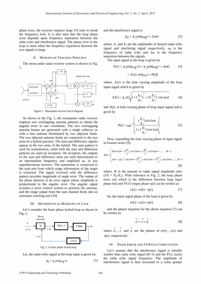
II. MONOPULSE TRACKING PRINCIPLE
The mono pulse radar receiver system is shown in Fig.
1.
Figure 1. Monopulse receiver block diagram
As shown in the Fig. 1, the monopulse radar receiver
employs two overlapping antenna patterns to obtain the
angular error in one coordinate. The two overlapping
antenna beams are generated with a single reflector or
with a lens antenna illuminated by two adjacent feeds.
The two adjacent antenna feeds are connected to the two
arms of a hybrid junction. The sum and difference signals
appear at the two arms of the hybrid. The sum pattern is
used for transmission, while both the sum and difference
patterns are used on reception. On reception, the outputs
of the sum and difference arms are each heterodyned to
an intermediate frequency and amplified as, in any
superhetrodyne receiver. The transmitter is connected to
the sum arm from which range information of the target
is extracted. The signal received with the difference
pattern provides magnitude of angle error. The output of
the phase detector is an error signal whose amplitude is
proportional to the angular error. The angular signal
actuates a servo control system to position the antenna,
and the range output from the sum channel feeds into an
automatic tracking unit [10].
III. MATHEMATICAL MODELING OF LOOP
Let’s consider the basic phase locked loop as shown in
Fig. 2.
Fig. 2. A basic phase locked loop
Let, the radar echo signal at the loop input is given by:
)sin(11 tifXA (1)
and the interference signal is
)sin(22 ttifXA (2)
where, X1 and X2 are the amplitudes of desired radar echo
signal and interfering signal respectively, if is the
frequency of radar echo and is the frequency
separation between the signals.
The input signal to the loop is given by
)sin(2)sin(1)( ttifXtifXtY (3)
)](sin[)( tttX if
where, )(tX is the time varying amplitude of the loop
input signal which is given by
tX
X
X
XtXtX cos)(2)(1)()(
1
2
1
22
1 (4)
and )(t is time varying phase of loop input signal and is
given by
tX
X
tX
X
t
cos)(1
sin)(
tan)(
1
2
1
2
1 (5)
Now, expanding the time varying phase of input signal
in Fourier series [9]:
1........,3sin)3
(2sin)2
(sin)(
1........,3sin)3
(2sin)2
(sin
)(32
32
1 RtRtRtRt
RtRtRtR
t
(6)
where, R is the jammer to radar signal amplitude ratio
(J/S = X2/X1). With reference to Fig. 2, the loop phase
error (t) which is the difference between loop input
phase (t) and VCO output phase (t) can be written as:
)()()( ttt (7)
So, the input signal phase of the loop is given by
)()()( ttt (8)
and the phasor equation for the above equation (7) can
be written as:
(9)
where
,
and
are the phasor of )(t , )(t and
)(t respectively.
IV. PHASE ERROR AND J/S RATIO COMPUTATION
Let’s assume that the interference signal is initially
smaller than radar echo signal (R<1) and the PLL tracks
the radar echo signal frequency. The amplitude of
interference signal is then increased to a value greater
International Journal of Electronics and Electrical Engineering Vol. 3, No. 2, April, 2015
©2015 Engineering and Technology Publishing 101
than radar echo signal. For R>1, the mathematical
analysis shows that, the phase detector output is written
as:
180sin)( 0 ttt (10)
where, is the phase of (t) and is dc phase of VCO.
So, the VCO output which is the filtered version of (t) is
given by
)180sinsin()( 0 ttt (11)
Expanding )(t in terms of fundamental harmonics,
second and higher order harmonics, it is given by
equations (12), (13) and (14) respectively as:
tJJt sin][)( 20 (12)
tJtJJt 2sinsin][)( 120 (13)
.....3sin32sinsin][)( 1120 tJtJtJJt
(14)
So, the input phasor equation (from equation (9)) for
fundamental harmonics, second and higher order
harmonics are obtained and are given in equation (15),
(16) and (17) respectively as:
)(][ 20 jGJJ
(15)
)2()(][ 120
jGJjGJJ (16)
.....)3(3sin)2()(][ 2120
jtGJjGJjGJJ
(17)
where, J 0 , J1 and J 2 is zero order, first and second
order Bessel function respectively and )( jG is the loop
transfer function and is given by:
)]()(2
)2( 2
1[)(
Bj
BjG (18)
where, is loop damping ratio and B is loop bandwidth.
So, from these phasor equations, the input signal phase is
determined for a given loop phase error and then J/S ratio
is obtained. From the equation (15), (16) and (17), the
phasor diagram for = 0.707 & 1.0 and = 1.4B, 2B
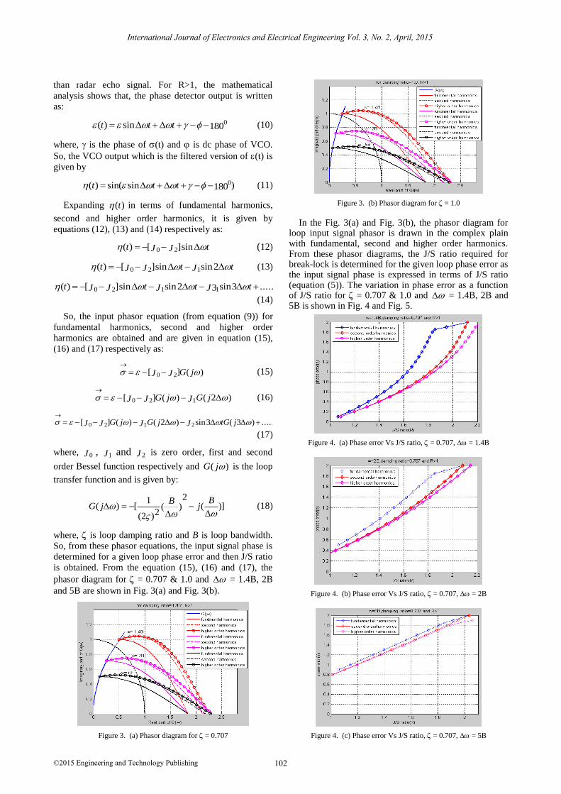
and 5B are shown in Fig. 3(a) and Fig. 3(b).
Figure 3. (a) Phasor diagram for = 0.707
Figure 3. (b) Phasor diagram for = 1.0
In the Fig. 3(a) and Fig. 3(b), the phasor diagram for loop input signal phasor is drawn in the complex plain with fundamental, second and higher order harmonics. From these phasor diagrams, the J/S ratio required for break-lock is determined for the given loop phase error as the input signal phase is expressed in terms of J/S ratio (equation (5)). The variation in phase error as a function of J/S ratio for = 0.707 & 1.0 and = 1.4B, 2B and 5B is shown in Fig. 4 and Fig. 5.
Figure 4. (a) Phase error Vs J/S ratio, = 0.707, = 1.4B
Figure 4. (b) Phase error Vs J/S ratio, = 0.707, = 2B
Figure 4. (c) Phase error Vs J/S ratio, = 0.707, = 5B
International Journal of Electronics and Electrical Engineering Vol. 3, No. 2, April, 2015
©2015 Engineering and Technology Publishing 102
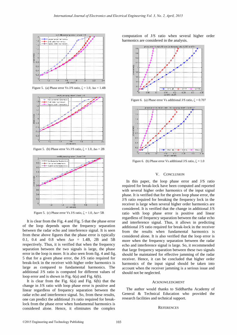
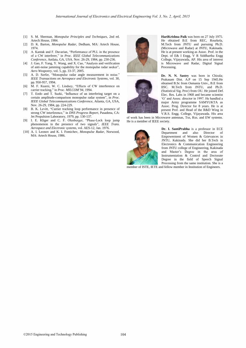
Figure 5. (a) Phase error Vs J/S ratio, = 1.0, = 1.4B
Figure 5. (b) Phase error Vs J/S ratio, = 1.0, = 2B
Figure 5. (c) Phase error Vs J/S ratio, = 1.0, = 5B
It is clear from the Fig. 4 and Fig. 5 that the phase error
of the loop depends upon the frequency separation
between the radar echo and interference signal. It is seen
from these above figures that the phase error is typically
0.1, 0.4 and 0.8 when = 1.4B, 2B and 5B
respectively. Thus, it is verified that when the frequency
separation between the two signals is large, the phase
error in the loop is more. It is also seen from fig. 4 and fig.
5 that for a given phase error, the J/S ratio required for
break-lock in the receiver with higher order harmonics is
large as compared to fundamental harmonics. The
additional J/S ratio is computed for different values of
loop error and is shown in Fig. 6(a) and Fig. 6(b).
It is clear from the Fig. 6(a) and Fig. 6(b) that the
change in J/S ratio with loop phase error is positive and
linear regardless of frequency separation between the
radar echo and interference signal. So, from these results,
one can predict the additional J/s ratio required for break-
lock from the phase error when fundamental harmonics is
considered alone. Hence, it eliminates the complex
computation of J/S ratio when several higher order
harmonics are considered in the analysis.
Figure 6. (a) Phase error Vs additional J/S ratio, = 0.707
Figure 6. (b) Phase error Vs additional J/S ratio, = 1.0
V. CONCLUSION
In this paper, the loop phase error and J/S ratio
required for break-lock have been computed and reported
with several higher order harmonics of the input signal
phase. It is verified that for the given loop phase error, the
J/S ratio required for breaking the frequency lock in the
receiver is large when several higher order harmonics are
considered. It is verified that the change in additional J/S
ratio with loop phase error is positive and linear
regardless of frequency separation between the radar echo
and interference signal. Thus, it allows in predicting
additional J/S ratio required for break-lock in the receiver
from the results when fundamental harmonics is
considered alone. It is also verified that the loop error is
more when the frequency separation between the radar
echo and interference signal is large. So, it recommended
that large frequency separation between these two signals
should be maintained for effective jamming of the radar
receiver. Hence, it can be concluded that higher order
harmonics of the input signal should be taken into
account when the receiver jamming is a serious issue and
should not be neglected.
ACKNOWLEDGMENT
The author would thanks to Siddhartha Academy of
General & Technical Education who provided the
research facilities and technical support.
REFERENCES
International Journal of Electronics and Electrical Engineering Vol. 3, No. 2, April, 2015
©2015 Engineering and Technology Publishing 103
[1] S. M. Sherman, Monopulse Principles and Techniques, 2nd ed. Artech House, 1984.
[2] D. K. Barton, Monopulse Radar, Dedham, MA: Artech House,
1974. [3] A. Kantak and F. Davarian, “Performance of PLL in the presence
of a CW interferer,” in Proc. IEEE Global Telecommunications Conference, Antlata, GA, USA. Nov. 26-29, 1984, pp. 230-236.
[4] J. Gao, F. Yang, Y. Wang, and X. Cao, “Analysis and verification
of anti-noise jamming capability for the monopulse radar seeker”, Aero Weaponry, vol. 5, pp. 33-37, 2005.
[5] A. D. Serfer, “Monopulse radar angle measurement in noise.” IEEE Transactions on Aerospace and Electronic Systems, vol. 30,
pp. 950-957, 1994.
[6] M. F. Kuarsi, W. C. Lindsey, “Effects of CW interference on carrier tracking,” in Proc. MILCOM’94, 1994.
[7] T. Endo and T. Suzki, “Influence of an interfering target on a certain amplitude-comparison monopulse radar system”, in Proc.
IEEE Global Telecommunications Conference, Atlanta, GA, USA,
Nov. 26-29, 1984, pp. 224-229. [8] B. K. Levitt, “Carrier tracking loop performance in presence of
strong CW interference,” in DNS Progress Report, Pasadena, CA: Jet Propulsion Laboratory, 1979, pp. 130-137.
[9] I. E. Kliger and C. F. Olenberger, “Phase-Lock loop jump
phenomenon in the presence of two signals”, IEEE Trans. Aerospace and Electronic systems, vol. AES-12, Jan. 1976.
[10] A. I. Leonov and K. I. Fomichev, Monopulse Radar, Norwood, MA: Artech House, 1986.
HariKrishna Paik was born on 27 July 1975. He obtained B.E from REC, Rourkela,
M.Tech from JNTU and pursuing Ph.D.
(Microwave and Radar) at JNTU, Kakinada. He is at present working as Assoc. Prof. in the
Dept. of E& I Engg, V R Siddhartha Engg College, Vijayawada, AP. His area of interest
is Microwave and Radar, Digital Signal
Processing.
Dr. N. N. Sastry was born in Chirala;
Prakasam Dist. A.P on 15 Sep 1945.He obtained B.Sc from Osmania Univ., B.E from
IISC. M.Tech from JNTU, and Ph.D. (Statistical Sig. Proc) from OU. He joined Def.
Elec. Res. Labs in 1968 and became scientist
‘G’ and Assoc. director in 1997. He handled a
major Army programme SAMYUKTA as
Assoc. Prog. Director for 8 years. He is at present Prof. and Head of the R&D Wing in
V.R.S. Engg. College, Vijayawada. His area
of work has been in Microwave antennas, Txs, Rxs. and EW systems. He is a member of IEEE society.
Dr. I. SantiPrabha is a professor in ECE
Department and also Director of
Empowerment of Women & Grievances in JNTU, Kakinada. She did her B.Tech in
Electronics & Communication Engineering from JNTU college of Engineering, Kakinada
and Master’s Degree in the area of
Instrumentation & Control and Doctorate Degree in the field of Speech Signal
Processing from the same institution. She is a member of ISTE, IETE and fellow member in Institution of Engineers.
International Journal of Electronics and Electrical Engineering Vol. 3, No. 2, April, 2015
©2015 Engineering and Technology Publishing 104