Embed Size (px)
Citation preview
An elastic interface model of the mixed bending-tension (MBT) test
Stefano Bennati1, Paolo Fisicaro1, Luca Taglialegne1, Paolo S. Valvo1
1Department of Civil and Industrial Engineering, University of Pisa, Italy
E-mail: [email protected], [email protected],
[email protected], [email protected]
Keywords: Composite laminates, delamination, interface model, experimental testing.
SUMMARY. The mixed bending-tension (MBT) test has been introduced by Macedo et al. to
assess the interlaminar fracture toughness of laminates with low bending stiffness and strength in
the longitudinal direction. In the experimental setup, the delaminated specimen is adhesively
bonded to two pin-loaded metal beams. We have developed a mechanical model of the test, where
the specimen is modelled as an assemblage of two beams connected by an elastic interface, while
the metal beams are modelled as rigid beams. An analytical solution has been obtained by
applying classical beam theory. Furthermore, to better describe the experimental results, we have
developed also a cohesive zone model based on a bilinear traction-separation law.
1 INTRODUCTION
Delamination is a major failure mode for fibre-reinforced composite laminates. Within the
context of linear elastic fracture mechanics (LEFM), the propagation of delaminations is
commonly predicted based on the energy release rate, G. Several experimental procedures and
testing setups have been developed to assess delamination toughness under pure and mixed
fracture modes [1]. However, while standard testing procedures exist for unidirectional (UD)
laminated specimens with 0°-oriented fibres, the development of new testing procedures for
multidirectional laminates is still an open issue [2, 3].
The double cantilever beam (DCB) test is the simplest and most commonly used testing
method to determine the delamination toughness of laminated specimens under mode I. For UD
laminates the DCB test has been standardised by ISO [4] and other standards development
organisations. Nevertheless, its use turns out to be problematic – or impossible at all – when
applied to materials with very low bending stiffness and strength, as the failure of the arms in
bending may anticipate delamination growth [5]. To overcome this drawback – in particular, for
specimens with 90°-oriented fibres – Macedo et al. [6] have proposed a mixed bending-tension
(MBT) test, where the specimen is adhesively bonded to two pin-loaded metal beams (Fig. 1).
Following the same approach used for the asymmetric double cantilever beam (ADCB) [7] and
mixed mode bending (MMB) tests [8], we have developed a mechanical model of the MBT test,
where the specimen is modelled as an assemblage of two beams connected by an elastic interface.
The metal beams that transfer the load to the specimen are instead modelled as rigid beams. An
analytical solution has been obtained by applying classical beam theory. The elastic interface
model is able to predict the initial linearly elastic response, but not delamination growth. To this
aim, we have developed also a cohesive zone model based on a bilinear traction-separation law,
which turns out to be effective in reproducing some experimental results of the literature.
2 LINEAR ELASTIC INTERFACE MODEL
2.1 Mechanical model
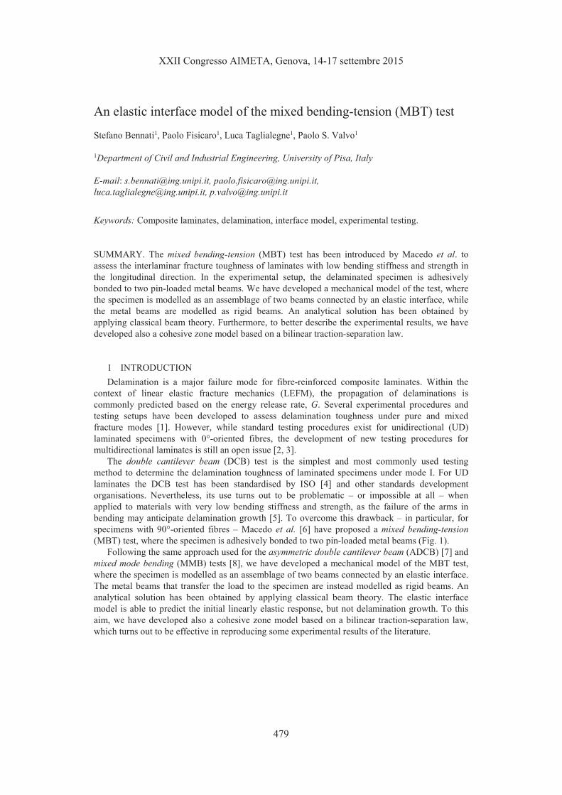
In the MBT test, a laminated specimen with a pre-implanted delamination of length a0 is
adhesively bonded to two equal metal beams, each of thickness t. The beams transfer the load, P,
applied by the testing machine, to the specimen (Fig. 1). We denote with l, b, and 2h the
specimen’s length, width, and thickness, respectively. The loading pins are placed at a distance d
from the left-hand end section of the specimen. A global reference system, Oxyz, is defined with
its origin at the centre of the specimen’s left-hand end section, and the x- and z-axes aligned with
the specimen’s longitudinal and transverse directions, respectively.
Figure 1: The MBT test specimen.
The delamination divides the specimen into two sublaminates of same thickness and
mechanical properties. In our mechanical model, we assume that the sublaminates are connected
by an interface of negligible thickness, regarded as a continuous distribution of linearly elastic
springs. Given the symmetry of the system with respect to the specimen’s mid-plane, no shear
stresses are transmitted through the interface. Hence, we consider that the distributed springs act
along the normal direction to the interface plane only. Accordingly, the normal interfacial stress is
( ) ( ) [ ]0, ,= ∆ ∈zx k w x x a lσ , (1)
where kz is the springs’ elastic constant and ∆w is the corresponding transverse relative
displacement.
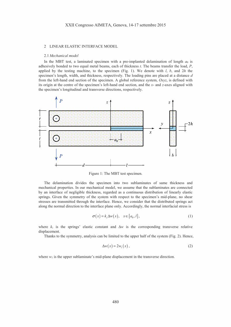
Thanks to the symmetry, analysis can be limited to the upper half of the system (Fig. 2). Hence,
( ) ( )12∆ =w x w x , (2)
where w1 is the upper sublaminate’s mid-plane displacement in the transverse direction.
We assume that the displacement of the specimen is led by that of the rigid beam, so that it can
be expressed as follows:
( ) ( )12
w x d xδ
θ= − + , (3)
where θ and δ respectively represent the rigid rotation and translation of the beam. In particular,
2δ is the displacement of the load application point (at x = −d).
Figure 2: Schematics of the upper half of the system.
Static equilibrium of the system requires that
( ) dσ= �l
a
P b x x (4)
( ) dσ= −�l
a
Pd b x x x . (5)
By substituting Eq. (3) into (1) and (2), and the result into (4) and (5), a linear equation set is
obtained, whose solution yields θ and δ. As a final result, we obtain the expressions of the
transverse displacement,
( )( )
( )
( )
2 2
1 3 3
2 3 2 3 23 2 + + + ++ += − +
− −z z
a d l a dl lP a d l Pw x x
bk bkl a l a(6)
and normal interfacial stress,
( )( )
( )
( )
2 2
3 3
2 3 2 3 226 2
a d l a dl lP a d l Px x
b bl a l aσ
+ + + ++ += − +
− −. (7)
2.2 Specimen’s compliance and energy release rate
Within the linearly elastic load-deflection response, the specimen’s compliance is defined as
δ=C P , where P is the applied load and � is the displacement of the load application point [1].
For the MBT test, δ = 2w1(−d) and the specimen’s compliance results
( )
( )
2 2 2
3
3 3 34 + + + + +=
−z
a d l a d dl lC
bk l a. (8)
Within LEFM, the energy release rate is defined as d d= −G V A , where V is the total potential
energy of the system and d d=A b a is the area of the new surface created by crack advancement
[1]. In this case, the well-known Irwin-Kies [9] relationship yields
2d
2 d=
P CG
b a. (9)
By substituting Eq. (8) into (9), the following expression is obtained
( )
( )
22
I 2 4
3 22 + +=
−z
d l aPG
b k l a, (10)
where the subscript I highlights the fact that the fracture propagates in pure mode I during the test.
3 COHESIVE ZONE MODEL
The linear elastic interface model presented in the previous section can be used successfully to
predict the experimental response in the initial linear elastic stage prior to the onset and
propagation of the delamination crack. The latter phenomena involve material damage and fracture,
which both can be taken into account by the assumption of a cohesive zone model [10].
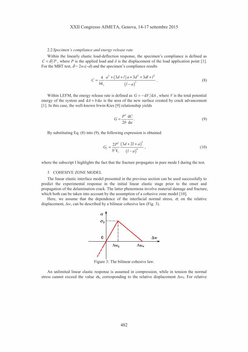
Here, we assume that the dependence of the interfacial normal stress, σ, on the relative
displacement, ∆w, can be described by a bilinear cohesive law (Fig. 3).
Figure 3: The bilinear cohesive law.
An unlimited linear elastic response is assumed in compression, while in tension the normal
stress cannot exceed the value σ0, corresponding to the relative displacement ∆w0. For relative

displacements included between ∆w0 and ∆wu, a softening behaviour is assumed, corresponding to
progressive material damage. For a relative displacement greater than ∆wu, fracture occurs.
According to the above, Eq. (1) is modified as follows:
( )
( )( )
( )( )
( )
[ ]
0 0
0
0 0 0
0
,
, , ,
0,
∆�∆ ≤ ∆�
∆�� ∆ − ∆�
= ∆ < ∆ ≤ ∆ ∈�∆ − ∆�
� ∆ < ∆���
u
u
u
u
w xw x w
w
w w xx w w x w x a l
w w
w w x
σ
σ σ , (11)
Eqs. (2) through (5) still hold and can be used to determine the response of the specimen
beyond the linearly elastic behaviour. For the sake of brevity, we omit here the details of the
calculations that involve substitution of Eq. (11) into the static equilibrium Eqs. (4) and (5) to
determine the values of δ and θ during the various stages of response. Actually, three stages can be
individualised in the specimen’s response:
- Stage I – Linearly elastic behaviour. As long as the opening displacement at the crack tip,
∆w(a), is less than ∆w0, the specimen’s response is linearly elastic. Neither material damage,
nor crack propagation occur during this stage;
- Stage II – Progressive material damage. When the opening displacement at the crack tip
attains the value ∆w0, damage of the material begins. As the test proceeds further, a damaged
zone of increasing length, c, develops ahead of the crack tip, while the delamination length is
constantly equal to a0 (Fig. 4). Correspondingly, the length of the zone where the material is
still linearly elastic decreases;
- Stage III – Crack propagation. When the opening displacement at the crack tip equals ∆wu,
fracture occurs. Then, the delamination length, a, increases and the damaged zone changes its
length accordingly, until complete delamination of the specimen is reached.
Figure 4: Stage II: the development of the damaged zone at the crack tip.
4 COMPARISON WITH EXPERIMENTAL RESULTS
By way of illustration, we consider an experimental study by Macedo et al. [6], who report on
the results of MBT tests on carbon/epoxy unidirectional [0] 26 and [90]26 laminated specimens. The
considered specimen had span l = 40 mm, width b = 20 mm, and thickness 2h = 4 mm; the initial
delamination length was a0 = 25 mm, obtained by inserting a 13 µm PTFE film at laminate half-
thickness during lamination. The metal beams were made of S235 structural steel and had
thickness t = 19 mm. The loading pins were placed at a distance d = 100 mm from the left-hand
end section of the specimen. The tests were conducted under imposed displacement conditions.
The main objective of the study was to obtain fracture initiation values, GIc, so that the albeit small
crack propagation length did not represent a problem.
The parameters characterising our mechanical model can all be determined from the
experimental results presented in [6]. In what follows we limit to the 0° unidirectional laminated
specimens, but the same procedure can be applied for the 90° laminated specimens. Firstly, the
value of the interface elastic constant, kz = σ0/∆w0 is obtained by applying a compliance calibration
strategy [11]. By inverting Eq. (8), we obtain
( )
( )
2 2 2
3
3 3 34 1z
a d l a d dl lk
b Cl a
+ + + + +=
−. (12)
By using in Eq. (12) the value of compliance, Cexp, measured during the experimental test (in
particular, at the end of the apparent linear elastic response), we obtain kz = 1275.8 N/mm3. This
value also corresponds to σ0 = 32.3 MPa and ∆w0 = 0.025 mm. The ultimate relative displacement
was determined as ∆wu = 0.045 mm by matching the theoretical and experimental values of
displacement that correspond to the maximum applied load.
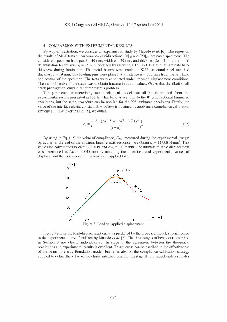
Figure 5: Load vs. applied displacement.
Figure 5 shows the load-displacement curve as predicted by the proposed model, superimposed
to the experimental curve furnished by Macedo et al. [6]. The three stages of behaviour described
in Section 3 are clearly individualised. In stage I, the agreement between the theoretical
predictions and experimental results is excellent. This success can be ascribed to the effectiveness
of the beam on elastic foundation model, but relies also on the compliance calibration strategy
adopted to define the value of the elastic interface constant. In stage II, our model underestimates
somehow the maximum value of the load, although gathering the correct trend of the curve. Due to
the shortness of the crack propagation length, the experimental tests did not reach stage III and we
have no elements for comparison.
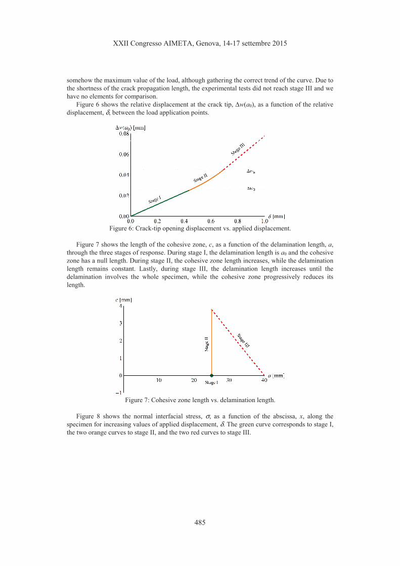
Figure 6 shows the relative displacement at the crack tip, ∆w(a0), as a function of the relative
displacement, δ, between the load application points.
Figure 6: Crack-tip opening displacement vs. applied displacement.
Figure 7 shows the length of the cohesive zone, c, as a function of the delamination length, a,
through the three stages of response. During stage I, the delamination length is a0 and the cohesive
zone has a null length. During stage II, the cohesive zone length increases, while the delamination
length remains constant. Lastly, during stage III, the delamination length increases until the
delamination involves the whole specimen, while the cohesive zone progressively reduces its
length.
Figure 7: Cohesive zone length vs. delamination length.
Figure 8 shows the normal interfacial stress, σ, as a function of the abscissa, x, along the
specimen for increasing values of applied displacement, δ. The green curve corresponds to stage I,
the two orange curves to stage II, and the two red curves to stage III.
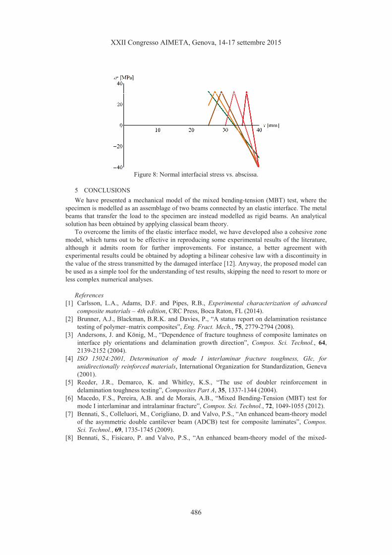
Figure 8: Normal interfacial stress vs. abscissa.
5 CONCLUSIONS
We have presented a mechanical model of the mixed bending-tension (MBT) test, where the
specimen is modelled as an assemblage of two beams connected by an elastic interface. The metal
beams that transfer the load to the specimen are instead modelled as rigid beams. An analytical
solution has been obtained by applying classical beam theory.
To overcome the limits of the elastic interface model, we have developed also a cohesive zone
model, which turns out to be effective in reproducing some experimental results of the literature,
although it admits room for further improvements. For instance, a better agreement with
experimental results could be obtained by adopting a bilinear cohesive law with a discontinuity in
the value of the stress transmitted by the damaged interface [12]. Anyway, the proposed model can
be used as a simple tool for the understanding of test results, skipping the need to resort to more or
less complex numerical analyses.
References
[1] Carlsson, L.A., Adams, D.F. and Pipes, R.B., Experimental characterization of advanced
composite materials – 4th edition, CRC Press, Boca Raton, FL (2014).
[2] Brunner, A.J., Blackman, B.R.K. and Davies, P., “A status report on delamination resistance
testing of polymer–matrix composites”, Eng. Fract. Mech., 75, 2779-2794 (2008).
[3] Andersons, J. and König, M., “Dependence of fracture toughness of composite laminates on
interface ply orientations and delamination growth direction”, Compos. Sci. Technol., 64,
2139-2152 (2004).
[4] ISO 15024:2001, Determination of mode I interlaminar fracture toughness, GIc, for
unidirectionally reinforced materials, International Organization for Standardization, Geneva
(2001).
[5] Reeder, J.R., Demarco, K. and Whitley, K.S., “The use of doubler reinforcement in
delamination toughness testing”, Composites Part A, 35, 1337-1344 (2004).
[6] Macedo, F.S., Pereira, A.B. and de Morais, A.B., “Mixed Bending-Tension (MBT) test for
mode I interlaminar and intralaminar fracture”, Compos. Sci. Technol., 72, 1049-1055 (2012).
[7] Bennati, S., Colleluori, M., Corigliano, D. and Valvo, P.S., “An enhanced beam-theory model
of the asymmetric double cantilever beam (ADCB) test for composite laminates”, Compos.
Sci. Technol., 69, 1735-1745 (2009).
[8] Bennati, S., Fisicaro, P. and Valvo, P.S., “An enhanced beam-theory model of the mixed-
mode bending (MMB) test – Part I: literature review and mechanical model”, Meccanica, 48,
443-462 (2013).
[9] Irwin, G.R. and Kies, J.A., “Critical energy release rate analysis of fracture strength”, Weld. J.
Res. Suppl., 33, 193-198 (1954).
[10] Yang, Q. and Cox, B., “Cohesive models for damage evolution in laminated composites”, Int.
J. Fract., 133, 107-137 (2005).
[11] Bennati, S. and Valvo, P.S., “An experimental compliance calibration strategy for mixed-
mode bending tests”, Proc. Mater. Sci., 3, 1988-1993 (2014).
[12] Valvo, P.S., Sørensen, B.F. and Toftegaard, H.L., “Modelling the double cantilever beam test
with bending moments by using bilinear discontinuous cohesive laws”, in Proc. 20th
International Conference on Composite Materials – ICCM 20, Copenhagen, Denmark, July
19-24, 2015 (2015).