Embed Size (px)
Citation preview
N A S A TECHNICAL NOTE N A S A TN D-5817 --- e, /
A N EVALUATION TWO GUIDANCE FOR A MANNED
OF SCHEMES
1. Repon No. ~- -
. . -
1 2. Government Accession NO.
NASA TN D-5817 I 4. Title and Subtitle
AN EVALUATION OF TWO GUIDANCE SCHEMES FOR A MANNED LUNAR LANDING
I 3. Recipient's
TECH LIBRARY KAFB, NM
5. Report Date May 1970
6. Performing Organization Code .
7. Author(s) 1 8. Performing Organization Report No.
George J. Hurt, Jr., Hugh P. Bergeron, and James J. Adams
9. Performing Organization Name and Address
NASA Langley Research Center Hampton, Va. 23365
L-676 1 10. Work Unit No.
125-19-11-05-23
"-I.
13. Type of Report and Period Covered 2. Sponsoring Agency Name and Address Technical Note
National Aeronautics and Space Administration 14. Sponsoring ATncy Code
Washington, D.C. 20546
. .
5. Supplementary Notes . . ..
~- -. . - . . "
6. Abstract
A fixed-base simulation of a lunar descent has been performed. The simulation, using instruments only, was conducted to compare two vehicle attitude programs: a single pitch-angle change and a multiple pitch-angle change. The comparison was made to determine a pilot's ability to complete a lunar descent from a 50 000-foot (15 240 meters) circular orbit to a hover altitude of approximately 1000 feet (305 meters) after a malfunction had forced the pilot to take control. System failures which would have caused a disaster if the pilot had not assumed control were randomly introduced during the simulated descents. Either of the two letdown profiles could be handled by the pilots. However, the multiple pitch-angle profile appeared to afford the pilot greater chance for success than did the single pitch-angle profile.
17. Key Words (Suggested by Authork))
Guidance schemes Man-machine relationship
. ~- - 18. Distribution Statement
. . ~ ". ~
Unclassified - Unlimited
19. Security Classif. (of this report) I. -
20. Security Classif. (of this page)
[ 21. ~ 0 ~ ; Unclassified Unclassified $3.00
P& 22. Rice*
-_______
*For sale by the Clearinghouse for Federal Scientific and Technical Information Springfield, Virginia 22151

AN EVALUATION OF TWO GUIDANCE SCHEMES
FOR A MANNED LUNAR LANDING
By George J. Hurt, Jr., Hugh P. Bergeron, and James J. Adams
Langley Research Center
SUMMARY
A fixed-base simulation of a lunar descent has been performed. The simulation, using instruments only, was conducted to compare two vehicle attitude programs. The comparison was made to determine a pilot's ability to complete a lunar descent from a 50 000-foot (15 240 meters) circular orbit to a hover altitude of approximately 1000 feet (305 meters) after a malfunction had forced the pilot to take control.
In the first attitude program, a single pitch-angle change was used. In the second program, a multiple pitch-angle change was used; this initially involved many small pitch-angle changes followed by a larger step change in pitch angle and a simultaneous change in thrust. After a descent was initiated in the automatic mode, the pilot could, if he so desired, take over and manually f ly the vehicle by controlling attitude and thrust magnitude. System failures were randomly introduced which, in a real situation, would have caused a disaster if the descent had been allowed to continue in the automatic mode. A reasonable approximation of the proper corrective procedure was usually sufficient to enable the pilot to take over and attain a satisfactory hover. However, terminal hover directly over the prime site could not be guaranteed. The multiple pitch-angle scheme appeared to afford the pilot the greater chance for success. For both guidance schemes, more accuracy was required in the altitude information than for the attitude or thrust information.
INTRODUCTION
Satisfactory termination of a powered descent and landing from a lunar orbit involves many factors which must be assessed for their effect on the outcome of the mission. Reference 1 is an example of a study of simplified guidance techniques. Knowledge of how to use the astronaut to best advantage in a complex space system is also necessary in order to determine reasonable alternatives which the crew must have available to allow them to cope with malfunctions that may occur during the descent.
A fixed-base simulation of a lunar descent from 50 000 feet (15 240 meters) to hover at 1000 feet (305 meters) has been conducted to determine the effect of the control program to be used on the letdown. Control information was presented on instruments. NASA test pilots served as test subjects. Two nominal attitude programs were studied: a simplified single pitch-angle change and a multiple pitch-angle change that initially involved many small changes in pitch angle followed by a final larger step change in pitch angle with a simultaneous reduction in thrust.
Beginning with the assumption that the pilot could not initiate an abort once a descent had commenced, a program was set up to evaluate a pilot's ability to accomplish a satisfactory descent with parts of the system being subject to malfunction. The pilot was instructed to make the best possible descent and to establish a hover, not necessarily over the prime target.
A descent was usually initiated in the automatic mode. During an automatic descent sequence, the pilot could, if he so desired, take over and manually fly the vehicle by con- trolling attitude and thrust magnitude in an attempt either to follow the descent profile that had been defined for the automatic run or to deviate from it as circumstances required. In all descents the pilot was required to establish hover by the manual mode of vehicle
SYMBOLS
matrix components of Euler transformation
universal gravitational constant, feet3/slug-second 2 (meters3/kilogram-second2)
magnitude of gravitational acceleration at earth's surface, feet/second 2 (rneters/second2)
magnitude of gravitational acceleration at moon's surface, feedsecond 2 (meters/second2)
altitude above moon's surface, feet (meters)
specific impulse, seconds
gain or arbitrary value
mass of moon, slugs (kilograms)
m mass of vehicle and fuel at any time, slugs (kilograms)
p,q,r vehicle rates, radians/second
R radial distance from vehicle to center of moon, feet (meters)
r M radius of moon, feet (meters)
S Laplace operator, per second
T thrust, pounds force (newtons)
t time, seconds
W earth weight of vehicle and fuel at any time, pounds force (newtons)
W O initial earth weight of vehicle and fuel, pounds force (newtons)
Xg,Yg, ZB vehicle body axes
XI, YI, ZI vehicle reference axes
Y central angle, radians
6 stick displacement (for pitch, roll, or yaw)
0, G, Q Euler angles, radians
dt differential with respect to time, per second
A single dot over a symbol denotes a derivative with respect to time. Double dots over a symbol denote a second derivative.
SIMULATION PROGRAM
Lunar Letdown Profile
The simulated lunar letdown was initiated from a 50 000-foot (15 240 meters) cir- cular orbit. The vehicle was oriented so that it was braking with maximum thrust in the direction of local horizontal. Since the central angle y transversed during descent did
3
not change greatly, the resultant change in vehicle attitude from the local horizontal, due to this angle change, was not considered (i.e., the surface of the moon was assumed to be flat, the XI-axis and the local horizontal being the same). A diagram of the axis-system orientation is presented in the following sketch:
path
Moon surface
In the single pitch-angle descent the initial pitch attitude was maintained until a predetermined time at which the vehicle was pitched down with the thrust oriented 20° below the local horizontal. This pitch attitude was maintained until a near-zero hori- zontal and vertical velocity was reached. At that point the pilot took over manually and established a hover. For the multiple pitch-angle descent several small attitude changes to approximate a continuous change were made at prescheduled intervals with a final large (35') change. Simultaneous with the final change in pitch angle was a reduction in braking thrust to 40 percent. This combination of pitch attitude and braking thrust level was maintained until a near-zero horizontal and vertical velocity was reached. Appro- priate equations of motion are given in appendix A.
A descent was usually initiated in the automatic mode. During some descents it was necessary for the pilot to take over control to correct for a programed malfunction. Typical programed malfunctions a r e as follows:
Damper failure on selected rotational axes
Attitude command meter failure (meter pegged to end of scale)
Attitude command meter failure (meter centered on scale)
4

f
Late automatic step-pitch initiation
Early automatic step-pitch initiation
Low thrust, 90 percent nominal
High thrust, 110 percent nominal
Misalined thrust: Oo, 5O, loo, 15' or 20'
Untrimmed 8-ball and attitude command meter (vehicle pitched up 5' when 8-ball and command meter read nominal (OO) pitch)
Rate bias in pitch, - second
Misalinement in initial attitude, 2' pitch-up 2 '7
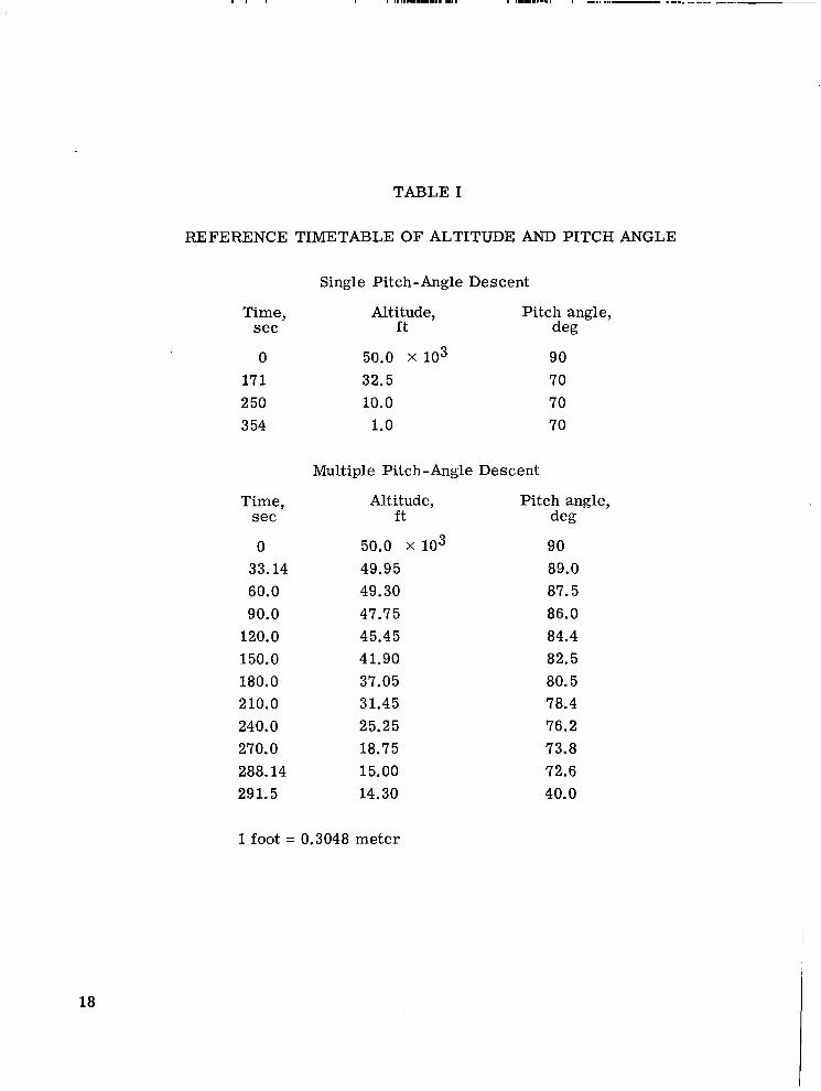
Since the pilot could expect failures, it was necessary that he monitor those instruments from which he could determine whether the letdown was following the nominal profile. The altimeter, clock, and 8-ball (three-axis attitude indicator), for example, could be used for an accurate check on the desired profile during the descent. A timetable of altitude and pitch angle is shown in table I for both profiles.
At the completion of the descent maneuver, that is, when a near-zero horizontal and vertical velocity was reached, the pilot normally took over control and established a hover condition (a pitch attitude of 0' and a reduced throttle setting to maintain the vertical and horizontal velocity components near zero). The hover was generally at an altitude of approximately 1000 feet (305 meters) with the vehicle over the landing site. Tests were usually terminated when hover was established.
Both descent maneuvers were programed so that an imaginary aiming point was located approximately 10 statute miles (16 090 meters) beyond the landing site. This value was used to insure that the reference point would always be in front of the vehicle and would in an actual descent provide a visual reference for the pilot. For this simula- tion program this visual reference was not used. However, all horizontal data presented in figures 2 to 14 are referenced to this point.
Vehicle
Pilot control was exercised from inside the capsule of a modified Mercury proce- dures trainer originally used in the astronaut training program. Figure 1 shows the capsule and the operator's console. The attitude (8-ball) of the vehicle was controlled by the three-axis sidearm controller integral to the procedures trainer. A small dead band was inserted in the controller to insure zero output signal for a hand's-off configuration. Maximum controller deflection provided a maximum angular acceleration of 8'/second2,
5

a maximum angular velocity of 8O/second, and a theoretically unlimited rotational capa- bility. These values are in the range specified in the lunar module design. When the rate feedback signal is taken out (i.e., the equivalent of a damper failure), the theoretical maximum angular velocity also becomes unlimited. The attitude control system created pure couples and the translational thrust was assumed to be directly through the center of gravity. The center of gravity is always considered to be the center of the vehicle reference axis system. The amount and mass of the attitude fuel and the change in vehi- cle rotational dynamics due to fuel usage by the main engine was not considered in the computations.
Translation was accomplished by the appropriate rotation of the vehicle and thrust vector. The thrust-mass ratio was 12.88 feet/second2 (3.9 meters/second2) initially, with the total mass of vehicle and main-engine fuel being slugs - that is, 815.2 slugs (11 897 kilograms). As the fuel mass decreased, the thrust-mass ratio correspondingly increased. The comparable thrust-weight ratio which was 0.4 at the beginning of the letdown increased to 0.827 at the instant before fuel exhaustion. A spe- cific impulse of 310 seconds was used.
32.2
Instrumentation
A three-axis 8-ball was used to supply attitude information to the pilot. A zero- center vertical-scale pitch-error command meter was used to indicate when the desired pitch attitude was being maintained. The altimeter was a single-needle di.al instrument on which the complete span of the dial (320O) represented 50 000 feet (15 240 meters). However, when 5000 feet (1524 meters) was indicated, the scaling was automatically changed so that the 320' span represented the final 5000 feet. A dial meter was used to indicate horizontal velocity, with zero horizontal velocity indicated when the needle was centered. The needle movement was proportional to the horizontal velocity up to the maximum meter reading of 570 feet/second (174 meters/second). The direction of needle motion indicated the direction of vehicle translation along the XI-axis. The needle position gave the pilot a crude estimation of the horizontal motion, somewhat comparable to the accuracy he might obtain by looking out of a window. A fuel meter indicated the percentage of fuel remaining. The thrust was throttlable from 100 percent of programed thrust to a minimum of 10 percent. The position of the thrust lever gave the pilot a gen- eral idea of the percent of available thrust he was commanding. For the multiple pitch- angle letdown, a retractable stop on the throttle quadrant allowed the pilot to position accurately the thrust lever for the programed thrust change. With the stop retracted, he could manually command the thrust level he desired in order to cope with possible pro- gramed malfunctions.
6
RESULTS AND DISCUSSION
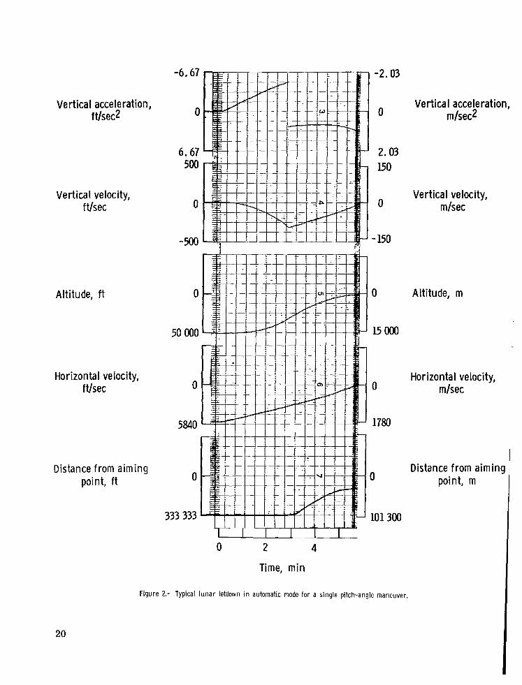
A typical time history of the single pitch-angle lunar letdown maneuver in the auto- matic mode is shown in figure 2. The simulated letdown was initiated from a 50 000-foot (15 240 meters) circular orbit. The vehicle was oriented so that it was braking with maximum thrust in the direction of horizontal translation. The initial pitch angle was nominally maintained for an elapsed time of 171.0 seconds. At that time the vehicle was pitched down until the thrust vector was 20° below the local horizontal. Themaltitude at that point was approximately 32 500 feet (9906 meters) and the horizontal distance from the target site was approximately 52 nautical miles (96 304 meters). The 70° pitch atti- tude was maintained until a near-zero horizontal and vertical velocity was reached; the pilot then took over and manually established a hover. For the single pitch-angle descent, the total elapsed time was nominally about 354 seconds.
All descents began in the automatic mode. The pilot could, if he so desired, over- ride the automatic control and manually fly the vehicle by controlling attitude and thrust magnitude in an attempt either to follow the same profile defined for the automatic descent or to deviate from it. Because the pilot could expect failures, he was required to monitor those instruments from which he could determine if the automatic letdown was following the nominal profile.
For the single pitch-angle descent, the pilot would monitor time and altitude as an indication of how well the vehicle was following the desired profile. The pilot was able to use the altimeter and clock for an accurate check on the profile, for example, at onset of altimeter motion (nominally 1 minute), at the 20° pitch-down point, and again at hover. The pilot learned from experience to interpolate the progress from point to point and was able to predict how well the descent was progressing and what, if any, corrective action was necessary.
A typical time history of a manually controlled single pitch-angle descent performed by an experienced National Aeronautics and Space Administration test pilot is shown in figure 3. The pilot was readily able to control the vertical acceleration so that for the manually controlled descent the vertical velocity did not have any large variations and, therefore, the altitude trace was correspondingly smooth down to and through the hover period. The primary information cue for this descent was obtained from a clock, an . 8-ball, an altimeter, and a horizontal velocity meter.
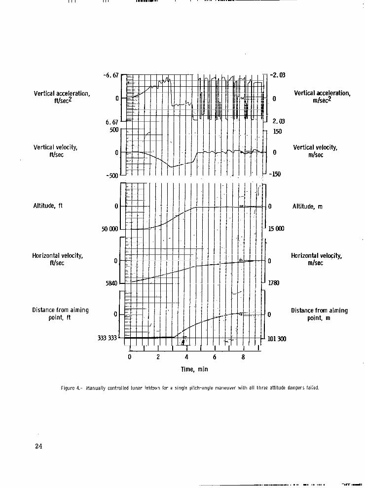
The effect of a programed malfunction, such as an attitude damper failure (all three axes), is illustrated in figure 4. The deterioration of the maneuvers is minor. However, if the pilot workload was increased by adding a side task in the form of system failures (appendix B), the deterioration was significant (ref. 2).
7
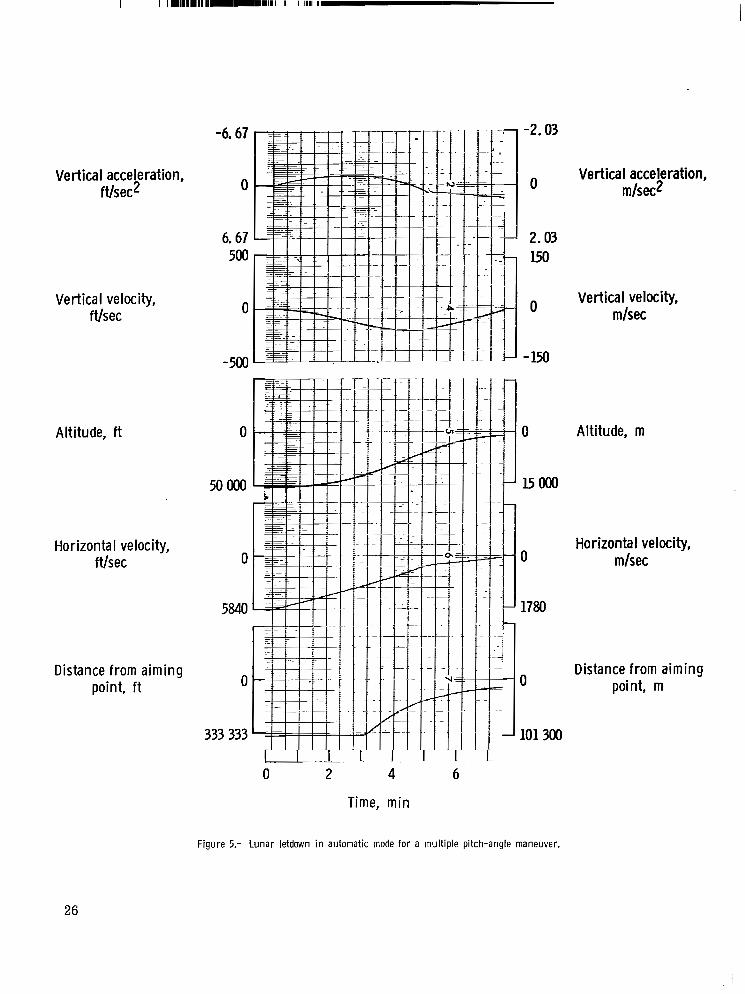
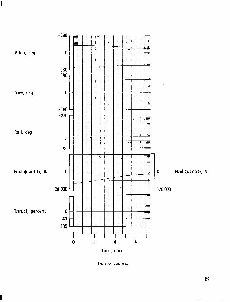
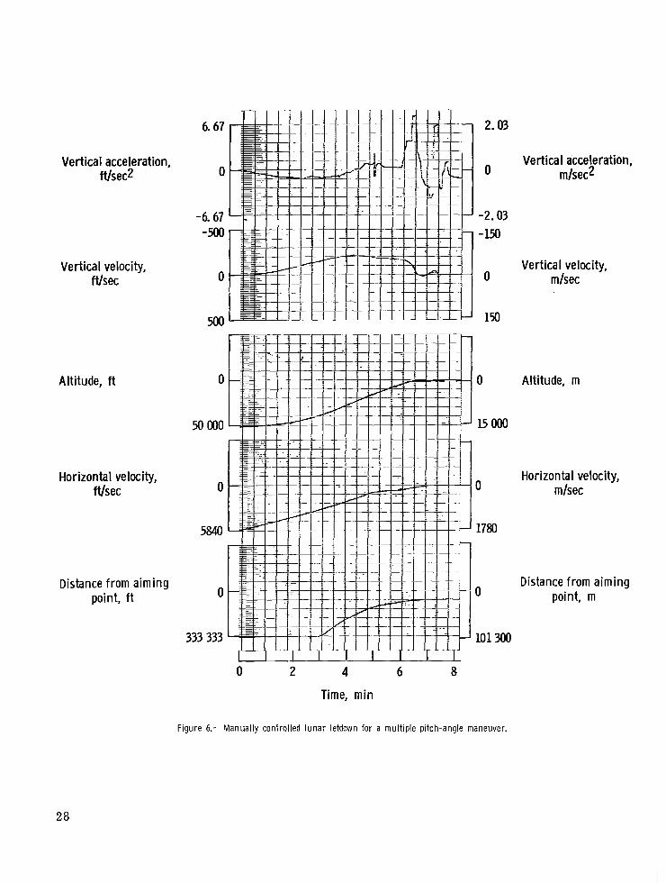
An example of the multiple pitch-angle letdown maneuver in the automatic mode is presented in figure 5. The initial pitch angle of 90° was maintained for 33.14 seconds. From that time, programed changes (table I) were automatically initiated in pitch until 288.14 seconds had elapsed and then a rapid change in pitch from 72.6' to 40.0' was per- formed. Simultaneous with this pitch change the throttle was reduced to 40 percent of available thrust. These two changes were accomplished between the elapsed times of 288.14 seconds and 291.5 seconds. At the completion of this maneuver the altitude was approximately 14 300 feet (4359 meters) and the horizontal distance from the target was approximately 20 nautical miles (37 040 meters). This combination of pitch angle and thrust level was maintained until the vertical and horizontal velocity components were near zero, at which time the pilot would switch to manual control and establish a hover. The scheduled elapsed time for a multiple pitch-angle descent was 420 seconds. A piloted multiple pitch-angle descent is illustrated by figure 6. The terminal conditions are typ- ical of a "successful" test.
A comparison of figures 4 and 7 indicates that the pilot was able to handle more efficiently a damper failure in a multiple pitch-angle descent than that in a single pitch- angle descent. The oscillations in the vertical time histories were reduced.
With few exceptions the pilots were able to cope with the programed malfunctions and with the imposed system failures. A reduction of initial braking appeared to be potentially the most critical situation. The first altitude-time checkpoint was reached at approximately 1 minute after the initial braking had begun. If the programed malfunc- tion is a reduction in braking thrust, then the pilot must take immediate corrective mea- sures. A delay in assuming command or a misinterpretation of the malfunction could cause the descent to terminate below the lunar surface (that is, in a crash). A typical example of a crash due to pilot delay in assuming control is illustrated in figure 8. In this descent maneuver, the pilot did not correctly interpret the situation until it was too late to prevent a crash.
The normal corrective procedure in the event of reduced thrust called for the pilot to assume manual control and pitch down to increase vertical braking. This action would of course result in a further reduction of the braking in the horizontal direction and cause an overshoot of the primary landing site. A typical example of reduced thrust leading to an overshoot of the landing site is presented in figure 9. Correct analysis by the pilot enabled him to successfully terminate the flight. These data suggest that the time inter- val of 1 minute before the first altitude-time checkpoint is too long. Earlier knowledge of a thrust malfunction would enable the pilot to more readily adjust his descent pattern and, therefore, be able to terminate the descent nearer the predicted site. This infor- mation would also reduce the probability of impact with the surface. Accurate indicators
8

for changes in vertical velocity and horizontal velocity would be essential for this early. detection (less than 1 minute into the descent) of a thrust malfunction.
A second potentially critical malfunction was an early (or late) pitch change initi- ation. The programed pitch step change was normally scheduled to occur at an elapsed time of 171.0 seconds for the single pitch-angle profile and 288.14 seconds for the mul- tiple pitch-angle profile. If the elapsed time and the corresponding altitude (as predicted for the profile) were progressing satisfactorily, then the pilot would assume command if the vehicle attempted to pitch prior to the programed time or if a pitch did not occur at the programed time. Either version of the malfunction could be programed. As may be seen in figures 10 and 11, the pilot was able to compensate for the effect of an incorrect time of pitch initiation by adjusting his pitch (thrust) attitude. The pilot was generally able to compensate for this malfunction in such a manner as to approximate closely the predicted termination of a normal automatic descent. However, some spread could be predicted for the final horizontal distance from the landing site. The spread in horizontal and vertical hover for the termination of several descents is shown in figure 12.
An untrimmed condition that,produced a rate bias in pitch attitude was not a diffi- cult problem for the pilot to solve. An illustration of the pilot's ability to cope with this situation is presented in figure 13.
Initially it was assumed that the inclusion of a zero-center pitch error command meter would save scan time and assist the pilot in maintaining surveillance of the nominal pitch attitude during a descent. However, it was found that this command meter was not a requirement and the pilot could obtain adequate pitch information directly from the 8-ball.
A test descent was usually terminated when the pilot had established a hover. The display instruments and their scaling as used in this study were considered below the accuracy and readability required to complete the maneuver from hover altitude (usually about 1000 feet (305 meters)) to touchdown. However, as a matter of interest the pilots were frequently allowed to continue the maneuver and attempt a touchdown. It was found that a successful touchdown at an alternate site could be made and still have 2 to 3 per- cent of the budgeted fuel remaining if horizontal translation to the initial target was not required. Figure 14 is an example of such a touchdown. Altitude and horizontal-velocity cues were considered by the test pilots to be "must have" items. Some descents were made under failure sequences that included a failure of the cockpit altimeter. Most of these descents were unsuccessful. The failed altimeter situation as used w a s unrealistic and was abandoned eariy in the test program. In the simulation, the only source of alti- tude information to the pilot was the cockpit altimeter. Under actual conditions with the lunar module at 0' pitch and roll attitude, it is assumed that the pilot will have out-of- the-window capability that will give him sufficient horizontal and vertical situation
9
I
information that would permit a satisfactory touchdown. However, one subject, an expe- rienced helicopter test pilot, commented that with a complete loss of altitude instrumenta- tion a touchdown would be uncertain on smooth terrain without nearby objects of known size. He further commented that the situation would be more critical if ,coupled with a minimum fuel supply.
A combination of system failures (appendix B), including life support, with malfunc- tions of thrust and control damping was not observed to have a significant effect if these malfunctions and failures occurred during the first or the middle portion of the letdown. However, if a combination of failures occurred during establishment of hover, the pilots would frequently be on the verge of losing control. In this situation, attitude control and altitude control are of prime importance, and life support corrections (where possible to postpone) a r e secondary. Although the pilot was generally able to cope with this set of conditions, it was usually at the risk of reducing his fuel supply to a submarginal amount. Under these conditions the multiple pitch-change profile appeared to afford the pilot greater leeway. The transition maneuvers for the multiple pitch-angle descent were less abrupt. The oscillations that were incurred were usually of a lesser magnitude and more readily controlled than those for the single pitch-angle descent.
CONCLUDING REMARKS
Results of a fixed-base piloted simulation of a lunar descent, conducted to evaluate astronauts' ability to monitor and supplement the automatic lunar module control system, led to the following comments.
The manually controlled lunar-module letdown from 50 000 feet (15 240 meters) to 1000 feet (305 meters) can be performed with a reasonable guarantee of success if a hard requirement is not made on the astronaut to accomplish a hover immediately over the prime landing site.
Failures were introduced that would have caused a disaster if the flight had been allowed to continue in the automatic mode. It appears therefore that an automatic-manual relation between vehicle and pilot would afford the best chance for a successful termina- tion of the flight, A reasonable approximation of the proper corrective procedure by the pilot was usually sufficient to allow him to accomplish a satisfactory hover.
il.
Either the single pitch-angle-change or the multiple pitch-angle-change letdown profile could be handled by the pilots. However, the multiple pitch-angle profile appar- ently afforded the pilot greater chance for success than the single pitch-angle profile.
Time, altitude, and attitude information were of critical importance to the pilot. Time might be estimated, vehicle attitude could possibly be established from some exter- nal visual reference, but altitude information was believed to be of utmost importance.
10

Accurate indicators for changes in vertical and horizontal velocity would be essen- tial for the early detection (less than 1 minute into the descent) of a thrust malfunction.
Langley Research Center, National Aeronautics and Space Administration,
Hampton, Va., February 17, 1970.
11
APPENDIX A
EQUATIONS USED IN LUNAR LETDOWN SIMULATION
Equations of Motion
The translation equations of motion used in this simulation were those for a point source mass moving in a planar force field. The equations are
YI = a2 *. T
where "1, a2, and a3 are matrix components of the Euler angle transformation which a r e defined by equations subsequently in the appendix. The YI-axis translation was part of the control problem even though it was not considered in the orbital computations. As long as R - 'M is relatively small, equation (1) can be simplified as follows:
Furthermore,
where K is a small number (-1.84 X 10⁻⁶) which gives the best linear approximation. Equation (1) now becomes
Also,
12

APPENDIX A
with
and
W = mgE
Attitude Equations
The attitude equations were written in transfer function form and were scaled to provide a maximum angular acceleration of 8O/second and a maximum angular velocity of 8O/second. The equations are
2
"- P - K 6 s + l
! I = - K 6 s + l
Euler Angle Transformation
The Euler angle transformation used was of the yaw-pitch-roll order and is written in matrix form as follows:
(COS + COS e) (sin J/ cos e) + sin e sin + - sin
The corresponding rate transformation equations are
6 = q cos 4 - r sin 4
l i /= r cos 4 + q sin 4 COS e
13
APPENDIX A
Since it was necessary to pitch the vehicle greater than 90' and since a 90' pitch angle produced a singularity point, a 90° roll was inserted for the initial or zero condi- tion. As a result, the yaw and pitch motions on the 8-ball were interchanged, and the vector relation of the body and inertial axes was changed to
and
fQr the initial conditions.
The axis transformation was also used to vector the thrust in the orbital equations. Thrust was defined to be in the YB-axis. The following equations (with the initial condi- tion of +90° in roll) were used for thrust alinement in the equations of motion:
-(sin + cos e) = a1
(cos + cos @ - sin + sin e sin @) = a2
14

APPENDIX B
SYSTEM-FAILURES TASK
The system failures were obtained from those systems present in the Mercury procedures trainer. However, because of the different requirements of the present sim- ulation, several of the systems could not be used. With the systems chosen, several lists of quasi-random arrangements were formed. These lists were then used to present the system failures to the test subjects. A typical list of failures, the corresponding indica- tions, and the required responses is presented in this appendix. It can be noted that sev- eral responses are required for certain failures because of the hierarchy of response predetermined for particular failure indications. This hierarchy of response was neces- sary since several failures generated the same indication.
Failure
1. c 0 2
2. Normal suit fan
3. Automatic-stabilization-and- control-systems inverter
4. No. 1 standby battery
5. No. 2 standby battery
6. No. 1 pitch fuse
I. No. 2 suit-fan fuse
8. Fan inverter
9. All main batteries
LO. No. 2 suit-fan fuse returned to operation
11. No. 1 yaw fuse
2. ac voltmeter
L3. Main and standby batteries returned to normal operation
Indication
Slow increase in reading of C02 partial pressure meter
Fan motor stops; dc ammeter drops from 20 to 15 amperes
Standby-inverter automatic warning light comes on
None yet
(See no. 4) ; dome temperature warning light and out-of-orbit-mode warning light go off
When pitch control not used, verbal indi- cation from experimenter only
When pitch control used, indication i s no response from the stick in pitch
Fan motor stops; dc ammeter drops from 20 to 15 amperes
Light dims, then returns to normal; ac voltmeter decreases, then returns to normal
Apparent failure of the following components: Fan motor, cabin lights, right side of con- trol fuel meter, dc voltmeter, dc ammeter, ac voltmeter, 8-bal1, emergency 02 meter, partial-pressure meter, suit- environment meter, and out-of-orbit-mode warning light
None yet
When yaw control not used, verbal indication from experimenter only
When yaw control used, indication is no response from the stick in yaw
Loose ac voltmeter
Verbal indication from experimenter
Response
Reach with left hand and pull decompression lever; after 2 to 3 seconds, return decompression lever and pull recompression lever; after 2 to 3 seconds, return recompression lever and make verbal notifica- tion of decompression to experimenter.
Switch to no. 2 suit-fan fuse and then switch to no. 1 suit fan.
Switch standby-inverter automatic tone switch off.
None yet.
Switch standby battery to on position.
Switch to no. 2 pitch fuse.
Switch to no. 2 pitch fuse.
Switch to no. 1 suit-fan fuse.
None yet.
Switch ammeter to bypass; switch ammeter back to normal; since standby-battery switch already on, switch isolated battery to standby position.
None yet.
Switch to no. 2 yaw fuse.
Switch to no. 2 yaw fuse.
Verbal response to experimenter.
Switch isolated battery to normal and switch standby battery to off.
15
APPENDIX B
r Failure
14. Automatic transfer of standby inverter
17. Normal suit fan returned to operation
19. Automatic-stabilization-and control-systems inverter returned to operation
20. dc voltmeter
21. All main batteries
i 22. Fan inverter returned to
normal "
23. No. 1 suit fan
24. Standby inverter
25. No. 1 roll fuse
26. Nos. 1 and 2 standby batteries
Indication
(See no. 3); 8-ball tumbles; (see no. 8); fan motor stops; cabin lights go off; failure of ac voltmeter; dc ammeter drops f rom 20 to 8 amperes
Fan motor stops; dc ammeter drops from 20 to 15 amperes
Apparent failure of the following components: Right side of control fuel meter; emer- gency 02 meter, suit-environment meter, and partial-pressure meter
None yet
Same indication a s f o r no. 9 (partial-pressur meter is already failed (see no. 16))
Tone (see no. 14)
Failure of dc voltmeter
Same indication as for no. 9 (partial-pressur meter is already failed (see nos. 16 and 18)); ammeter is already failed (see no. 18)
Tone yet
Fan motor stops
Fan motor stops; cabin lights go off; ac voltmeter fails
Nhen roll control not used, verbal indication from experimenter only
When roll control used, indication is no response from stick in roll
iame indication a s f o r no. 21
?an motor stops
. ..
Response
Switch fan inverter to standby.
Switch to no. 2 suit fuse (see no. 10).
hitch to 3-volt supply.
gone yet.
hitch ammeter to bypass (ammeter stays failed).
Vone.
Verbal response to experimenter.
jince ammeter already switched to bypass (see no. 18), switch standby battery to on position.
Tone yet.
h i t c h t o no. 1 suit fuse, next switch to normal suit fan, and then switch to no. 2 suit fuse (see nos. 1 5 and 17).
h i t c h fan inverter to normal.
jwitch to no. 2 roll fuse.
jwitch to no. 2 roll fuse.
iince ammeter already switched to bypass (see no. 18) and standby battery already switched on (see no. 21), Switch isolated battery to standby.
iwitch to no. 1 suit fuse, next switch to no. 1 suit fan, then switch to no. 2 suit fuse, and finally switch to no. 2 suit fan.
16

REFERENCES
1. Miller, G. Kimball, Jr.; and Fletcher, Herman S.: Fixed-Base-Simulator Study of Ability of Pilots To Perform Soft Lunar Landings by Using a Simplified Guidance Technique. NASA TN D-2993, 1965.
2. Bergeron, Hugh P.; Adams, James J.; and Hurt, George J., Jr.: Analysis of Human Response in Combined Control Tasks. NASA TN D-4356, 1968.
17
I 1 I
TABLE I
REFERENCE TIMETABLE OF ALTITUDE AND PITCH ANGLE
Single Pitch-Angle Descent
Time, Altitude, Pitch angle, sec f t deg
0 50.0 X 10³ 90 17 1 32.5 70 2 50 10.0 70 3 54 1.0 70
Multiple Pitch-Angle Descent
Time, Altitude, Pitch angle, sec f t deg
0 33.14 60.0 90.0
120.0 150.0 180.0 210.0 240.0 270.0 288.14 291.5
50.0 X 10³ 49.95 49.30 47.75 45.45 41.90 37.05 31.45 25.25 18.75 15.00 14.30
90 89.0 87.5 86.0 84.4 82.5 80.5 78.4 76.2 73.8 72.6 40.0
1 foot = 0.3048 meter
18
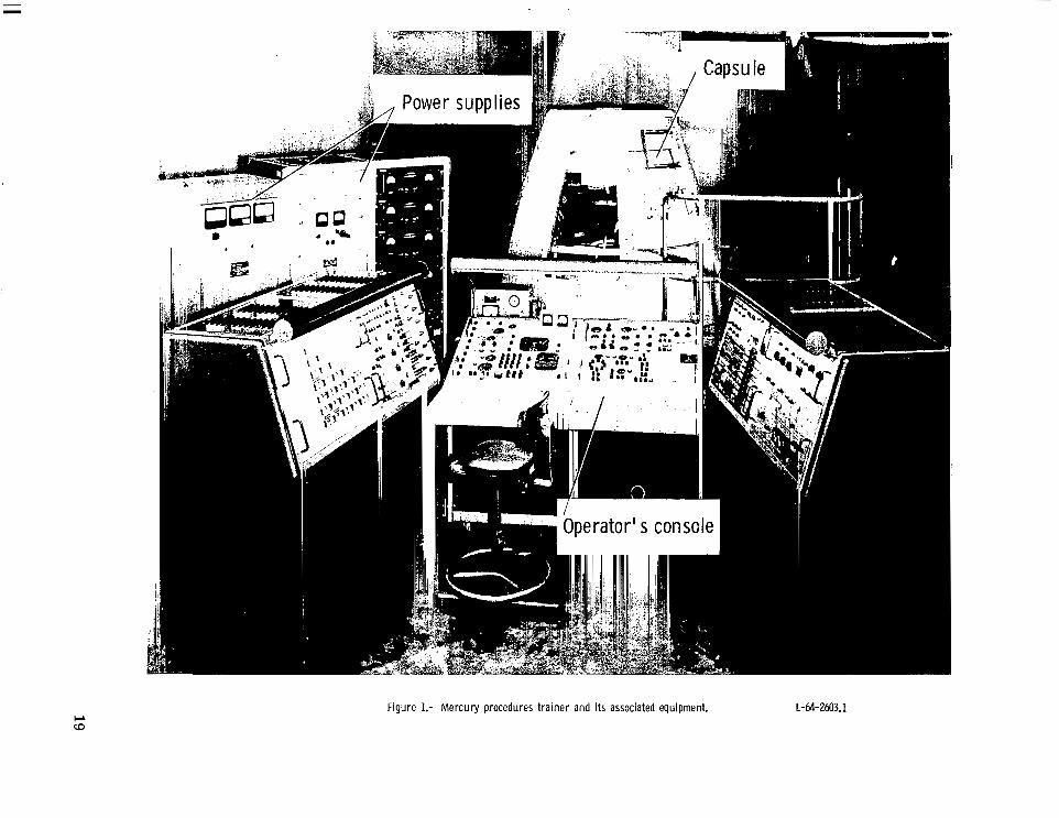
Figure 1.- Mercury procedures trainer and its associated equipment. L-64-2603.1
-6.67
Vertical acceleration, ft/sec2 0
Vertical velocity, ft/sec
Altitude, ft
Horizontal velocity, ft/sec
Dis dance from aiming point, ft
6.67 500
0
-500
0
50 000
0
5840
0
333 333
0 2 4
Time, m i n
-2.03
0 Vertical acceleration,
m/sec2
2.03
1 I5O Vertical velocity,
0 m/sec
-150
io Altitude, m
15000
1 Horizontal velocity,
m/sec
Distance from aimin! point, m
101 300
Figure 2.- Typical l u n a r letdown in automatic mode for a single pitch-angle maneuver
20

Pitch, deg
Yaw, deg
Roll, deg
180 -
0 1 L1
- 180
T 0 :
- 180 I
Fuel quantity, Ib
26000
Thrust, percent
2 4
Time, rnin
0 Fuel quantity, N
120 000
Figure 2.- Concluded.
21

Vertical acceleration, ftlsec2
Vertical velocity, ftlsec
-6.67
0
6.67 500
0
-500
Altitude, ft
Horizontal velocity, ftlsec
Distance from aiming point, ft
0
5oooo
0
5840
0
333 333
0 2 4
Time, min
6
I -1 i 1 1 I c
-r
1 -2.03 Vertical acceleration, l o m/sec2
7 I 2.03
Vertical velocity, m/sec
1 - 1 9
Altitude, m
J l5OOo 1
Horizontal velocity, mlsec
Distance from aiming point, m
Figure 3.- Typical manually controlled lunar letdown for a single pitch-angle maneuver.
22

Pitch, deg
Yaw, deg
Roll, deg
Fuel quantity, Ib
Thrust, percent
I I
0 Fuel quantity, N
120 000
0 2 4 6
Time, min
Figure 3.- Concluded.
23
I I I 1 1 1 1.111.1m.11 I I I .I I, I ... I., . "... ..-.."
Vertical acceleration, ftJsec2
Vertical velocity, ftlsec
Altitude, ft
Horizontal velocity, ftlsec
Distance from aiming point, ft
0 2 4 6
Time, min
T T
i I I I I I
-1 I 1
- 8
Vertical acceleration, m/sec*
Vertical velocity, mlsec
~
Altitude, m
0 Horizontal velocity,
m/sec
1780
1 0 Distance from aiming
point, rn
101 300
Figure 4.- Manually controlled lunar letdown for a single pitch-angle maneuver with all three attitude dampers failed.
24

Pitch, deg
Yaw, deg
Roll, deg
Fuel quantity, Ib
Thrust, percent
-180. L 1
180
26 Ooo
100 -
0 Fuel quantity, N
120 Ooo
4 6 8
Time, min
Figure 4.- Concluded.
25
Vertical acceleration, fttsec2
-6.67
0
6.67
Vertical velocity, ftlsec
Altitude, ft
Horizontal velocity, ftlsec
Distance from aiming point, ft
0
50 OOO
0
5840
0
333 333
t I
0 2 4
Time, min
6
t F I I I I .
I"
43 -I
1- l -
-2.03
0
2.03 HI
0
- 1%
0
101 300
Vertical acceleration, m/sec*
Vertical velocity, mlsec
Altitude, m
Horizontal velocity, mlsec
Distance from aiming point, m
Figure 5.- Lunar letdown in automatic mode for a multiple pitch-angle maneuver.
26
Pitch, deg -180 F 180 o [ 180 r
Yaw, deg 0
Roll, deg
Fuel quantity, Ib
-180 L - 270
0
90
0
26 000
Thrust, percent 0 40 100
i I 2
0 Fuel quantity, N
120 000
4 6
Time, min
Figure 5.- Concluded.
6.67 2.03
Vertical acceleration, tVsec2
Vertical velocity, ft/sec
Altitude, ft
Horizontal velocity, ft/sec
Distance from aiming point, ft
0
-6.67 -500
0
0
No00
0
5840
0
333 333
0
-2.03 - 1%
0
150
0
Eo00
0
1780
0
101 300
0 2 4 6 8
Time, min
Vertical acceleration, rn/sec*
Vertical velocity, m/sec
Altitude, m
Horizontal velocity, mlsec
Distance from aiming point, m
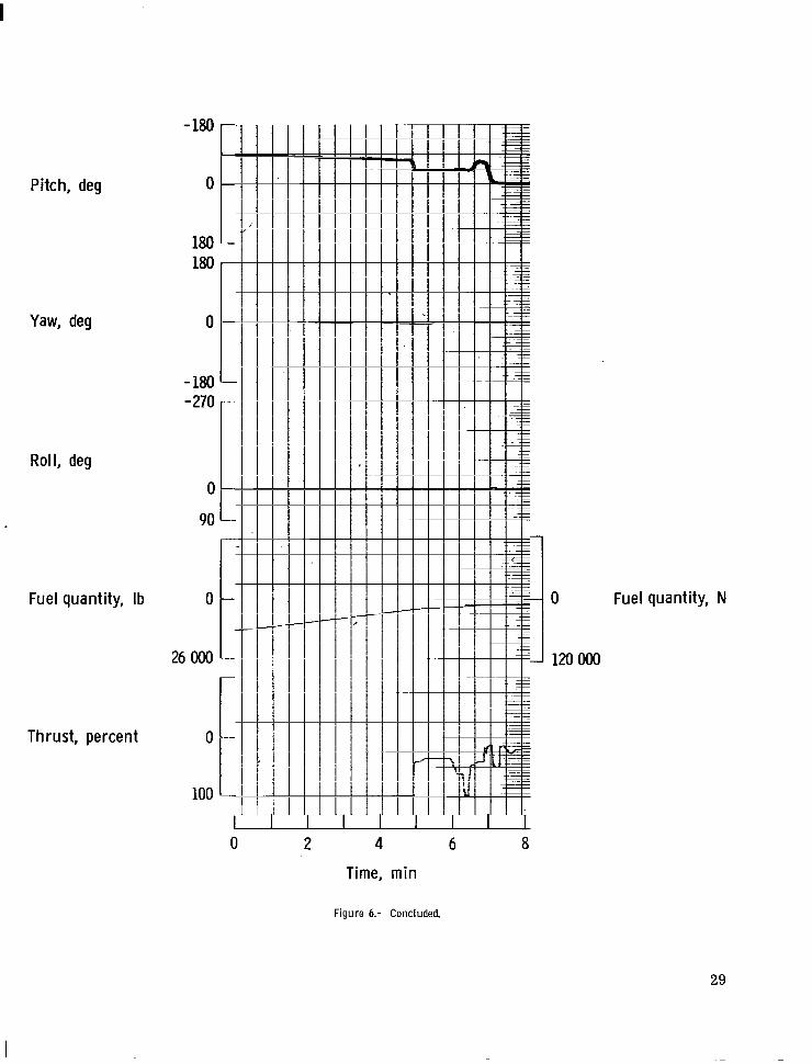
Figure 6.- Manually controlled lunar letdown for a multiple pitch-angle maneuver.
28
Pitch, deg
Yaw, deg
Roll, deg
Fuel quantity, Ib
Thrust, percent 0
100
2 4
0 Fuel quantity, N
120 OOO
Time, min
Figure 6.- Concluded.
6 8
-6.67 1- I
f I I
I
I
I I I
-I- I I I I I I I
I I I I
I I
1" I
I I I I I
I I I
I I I
% I
Vertical acceleration, rn/sec2
Vertical acceleration, ft/sec2 0
6.67 500
Vert ical velocity, mlsec
Vertical velocity ft/sec 0
-500
I I I I I I .
i I
I i I I I
I I I
I I
I
Y - 1 !
I
t I
I " I I I
Altitude, m Altitude, ft 0
15 OOO
0
5oOOO
Horizontal velocity, rn/sec
Horizontal velocity, ft/sec 0
1780
0
5840
Distance from aiming point, m
Distance from aiming point, ft 0 0
333 333 101 300
6 0 2 4
Time, m i n
Figure 7.- Typical example of pilot ability to safely control a multiple pitch-angle descent under abnormal conditions which included damper failures. Pilot assumed control when the scheduled pitch change at 288.14 seconds did not occur.
30
Pitch, deg
Yaw, deg
Roll, deg
- 180
0
180 180
0
- 180 - 270
0
90
Thrust, percent 0
100
0 2 4
Time, min
Figure 7.- Concluded.
8
0 Fuel quantity, N
120 OOO

I
-2.03
Vertical acceleration, ftlsec2
Vertical velocity, ft/sec
Altitude, ft
Horizontal velocity, ft/sec
Distance from aiming point, ft
2 4 6 a Time, min
0
0
-150
0
15 OOO
0
1788
Vertical acce eration, m/sec !!
Vertical velocity, mlsec
Altitude, m
0
101 300
Horizontal velocity, m/sec
Distance From aiming point, m
Figure 8.- Example of a crash due to pilot delay i n assuming manual control during a multiple pitch-angle descent. Pilot assumed command at final scheduled pitch initiation time.
32

Pitch, deg
Yaw, deg
- 180
0
180 180
0
- 180 - 270
Roll, deg
0
90
Fuel quantity, Ib 0
26OOo
Thrust, percent 0
100
0 2 4 6 8
Time, min
Figure 8.- Concluded.
0 Fuel quantity, N
120 OOO

-6.67 '-2.03
Vertical acceleration, ft/sec2
Vertical velocity, ft/SeC
Altitude, ft
Horizontal velocity, ft/SeC
Distance from aiming point, ft
0
6.67 500
0
-500
0
5840
0
333 333
0 2 4 6 8 10
Time, min
0
2.03 150
0
- 150
0
15 OOo
0
1780
0
101 m
Vertical acceleration, m/sec2
Vertical velocity, m/sec
Altitude, m
Horizontal velocity, m/sec
Distance from aiming point, m
Figure 9.- A typical example of site overshoot due to reduced th rus t dur ing a multiple pitch-angle descent. Pilot assumed command approximately 20 seconds before the scheduled pitch initiation.
34

Pitch, deg
Roll, deg
- 180
0
- 180 180
0
- 180 -270
Yaw, deg
0
90
Fuel quantity, Ib 0
26 OOO
Fuel quantity, N
Thrust, percent 0
100
0 2 4 6 8 10
Time, min
Figure 9.- Concluded.
3 5

Vertical acce eration, ft/sec 1
Vertical velocity, ft/sec
Altitude, ft
Horizontal velocity, ft/sec
Distance from aiming point, ft
6.67
0
-6.67 -500
0
2.03
0
-2.03 - 150
0
150
0
15 OOO
0
1780
Vertical acceleration, m/sec2
Vertical velocity, mlsec
Altitude, m
Horizontal velocity, m/sec
0 Distance from aiming
point, m
101 300
0 2 4 6 a Time, m i n
Figure 10.- An example of manual correction of an early pitch initiation during multiple pitch-angle descent in the automatic mode. The pilot assumed control approximately 5 seconds after the early pitch initiation occurred.
36
Pitch, deg
Yaw, deg
Roll, deg
Fuel quantity, Ib
Thrust, percent
180
0
- 180
0 2 4 6 a Time, min
Figure 10.- Concluded.
37

I 1 I . . .
I
Vertical acceleration, ft/sec2
Vertical velocity, ftlsec
Altitude, ft
Horizontal velocity, ftlsec
Distance from aiming point, ft
0
5oOOO
0
5840
0
333 333 I I I I I I I
0 2 4 6 8
Time, min
2.03
0
-2.03 - 150
0
150
0
15 OOO
0
1780
0
101 300
Vertical acceleration, mIsec2
Vertical velocity, mlsec
Altitude, m
Horizontal veiocity, mlsec
Distance from aiming point, m
Figure 11.- A n example of manual correction of a late pitch init iation during multiple pitch-angle descent in the automatic mode. The pilot assumed command instantly when the pitch initiation did not occur at the proper time.
38
Pitch, deg
Yaw, deg
Roll, deg
Fuel quantity, Ib
Thrust, percent
180 -
-180 -=
7
90 -
100 - I
2 4 6
Time, min
Figure 11.- Concluded.
0 Fuel quantity, N
120 OOO
8
39
cp 0 100 x 10
80 I - 28
24
60 - "-
40 I-
20 -
o Multiple pitch angle Single pitch angle
. o
16 -
12 'i c - W W
-0 W-
c I3
= a
a -
4 r
0 10 ,"-Landing site
/ ,-Aiming point
-20 -16 -12 -8 -4 0 4 8 12 16 20 24 28
Range, statute miles -40 -
I I I I I I I I - 40 - 30 - 20 - 10 0 10 ' 20 30 40
Range, meters
Figure 12.- Spread in horizontal and vertical hover for termination of several descents.
Vertical acceleration, ft/sec2
Vertical velocity, ft/sec
Altitude, ft >
Horizontal velocity, ft/sec
Distance from aiming point, f t
6.67
0
-6.67 -500
0
500
0 2 4 6 8
Time, min
2.03
0
-2.03 - 150
0
M
Q
0
1780
0
101 300
Vertical acceleration, m/sec2
Vertical velocity, m/sec
Altitude, m
Horizontal velocity, m/sec
Distance from aiming point, m
Figure l3.- A n example of the effect of an untr immed rate (f/second) in pi tch dur ing a multiple pitch-angle descent. The pilot assumed command approximately 25 seconds after descent began.
41
Pitch, deg
Yaw, deg
Roll, deg
Fuel quantity, Ib
Thrust, percent
- 180
0
180 180
0
- 180 - 270
0
90
0
26OOo
0
100
-]lam Fuel quantity, N
0 2 4 6 8
Time, min
Figure 13.- Concluded.
42
Vertical acceleration, ft/sec2
Vertical velocity, Wsec
. ..
2.03
0
-2.03 -1u)
0
150
Vertical acceleration, misec2
Vertical velocity, misec
~ Altitude, ft
Horizontal velocity, Wsec
Distance from aiming point, ft
0
MOOO
0
5840
0
333 333
0 2 4 6 8
Time, min
0
Eo00
0
1780
0
101 300
Altitude, m
Horizontal velocity, misec
Distance from aiming point, m
Figure 14.- A n example of a manually controlled descent from a hover to touchdown. The pilot assumed command at the end of a normal multiple pitch-angle descent. A hover was established and subsequently a descent was made to the surface.
43

Pitch, deg
Yaw, deg
Roil, deg
Fuel quantity, Ib
Thrust, percent
44
0 Fuel quantity, N
120 OOO
0 2 4 6 8
Time, min
Figure 14.- Concluded.
NASA-Langley, 1970 - 21 L-6761
NATIONAL AERONAUTICS AND SPACE ADMINISTRATION WASHINGTON, D. C. 20546
OFFICIAL BUSINESS FIRST CLASS MAIL
NATIONAL AERONAUTICS A- POSTAGE A N D FEES PAID
SPACE ADMINISTRATION
POSTMASTER: If Undeliverable (Section 15: Portal Manual) Do Not Retu
NASA SCIENTIFIC A N D TECHNICAL PUBLICATIONS
TECHNICAL REPORTS: Scientific and technical information considered important, complete, and a lasting contribution to existing knowledge.
TECHNICAL NOTES: Information less broad in scope but nevertheless of importance as a contribution to existing knowledge.
TECHNICAL idEMORANDUMS: Information receiving limited distribution because of preliminary data, security classifica- tion, or other reasons.
1
TECHNICAL TRANSLATIONS: Information published in a foreign language considered to merit NASA distribution in English.
SPECIAL PUBLICATIONS: Information derived from or of value to NASA activities. Publications include conference proceedings, monographs, data compilations, handbooks, sourcebooks, and special bibliographies.
TECHNOLOGY UTILIZATION PUBLICATIOh'S: Information on technology used by NASA that may be of particular
CONTRACTOR REPORTS: Scientific and technical information generated under a NASA Tec~,nology utilization R~~~~~~ and N ~ ~ ~ ~ , contract or grant and considered an important contribution to existing knowledge.
interest in commercial and other non-aerospace applications. Publications include Tech Briefs,
and Technology Surveys.
Details on the availability of these publications may be obtained from:
SCIENTIFIC AND TECHNICAL INFORMATION DIVISION
NATIONAL AERONAUTICS AND SPACE ADMINISTRATION Washington, D.C. 20546