Embed Size (px)
DESCRIPTION
wind load analysis
Citation preview
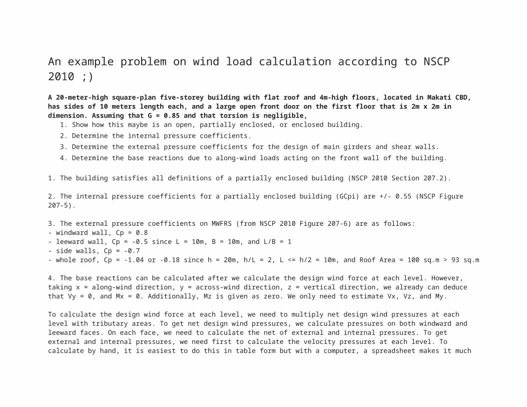
An example problem on wind load calculation according to NSCP 2010 ;)
A 20-meter-high square-plan five-storey building with flat roof and 4m-high floors, located in Makati CBD, has sides of 10 meters length each, and a large open front door on the first floor that is 2m x 2m in dimension. Assuming that G = 0.85 and that torsion is negligible,
1. Show how this maybe is an open, partially enclosed, or enclosed building.
2. Determine the internal pressure coefficients.
3. Determine the external pressure coefficients for the design of main girders and shear walls.
4. Determine the base reactions due to along-wind loads acting on the front wall of the building.
1. The building satisfies all definitions of a partially enclosed building (NSCP 2010 Section 207.2).
2. The internal pressure coefficients for a partially enclosed building (GCpi) are +/- 0.55 (NSCP Figure 207-5).
3. The external pressure coefficients on MWFRS (from NSCP 2010 Figure 207-6) are as follows:- windward wall, Cp = 0.8- leeward wall, Cp = -0.5 since L = 10m, B = 10m, and L/B = 1- side walls, Cp = -0.7- whole roof, Cp = -1.04 or -0.18 since h = 20m, h/L = 2, L <= h/2 = 10m, and Roof Area = 100 sq.m > 93 sq.m
4. The base reactions can be calculated after we calculate the design wind force at each level. However, taking x = along-wind direction, y = across-wind direction, z = vertical direction, we already can deduce that Vy = 0, and Mx = 0. Additionally, Mz is given as zero. We only need to estimate Vx, Vz, and My.
To calculate the design wind force at each level, we need to multiply net design wind pressures at each level with tributary areas. To get net design wind pressures, we calculate pressures on both windward and leeward faces. On each face, we need to calculate the net of external and internal pressures. To get external and internal pressures, we need first to calculate the velocity pressures at each level. To calculate by hand, it is easiest to do this in table form but with a computer, a spreadsheet makes it much easier:
Assume: Exposure Terrain Category B Case 2, Iw = 1.0, Kd = 0.85, Kzt = 1.0, V = 200 kph
Windward wall pz (kPa) Leeward wall pz (kPa)z (m) Kz qz (kPa) with +Gcpi with -Gcpi with +Gcpi with -Gcpi
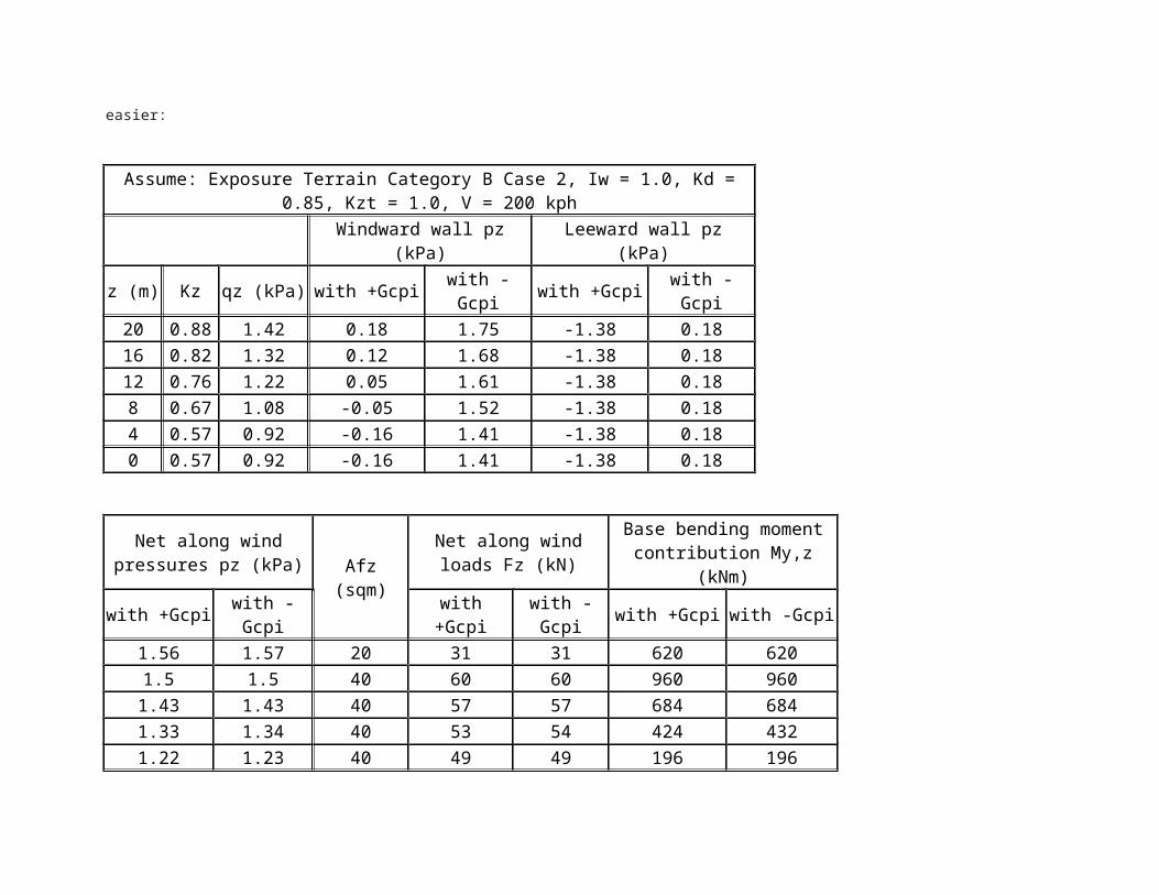
20 0.88 1.42 0.18 1.75 -1.38 0.1816 0.82 1.32 0.12 1.68 -1.38 0.1812 0.76 1.22 0.05 1.61 -1.38 0.188 0.67 1.08 -0.05 1.52 -1.38 0.184 0.57 0.92 -0.16 1.41 -1.38 0.180 0.57 0.92 -0.16 1.41 -1.38 0.18
Net along wind pressures pz (kPa) Afz (sqm)
Net along wind loads Fz (kN)
Base bending moment contribution My,z (kNm)
with +Gcpi with -Gcpi with +Gcpi with -Gcpi with +Gcpi with -Gcpi1.56 1.57 20 31 31 620 6201.5 1.5 40 60 60 960 9601.43 1.43 40 57 57 684 6841.33 1.34 40 53 54 424 4321.22 1.23 40 49 49 196 1961.22 1.23 20 24 25 0 0
Vx (kN) = 274 2762884 2892
My (kNm) =
Af,roof (sqm)
Roof loads 1, p (kPa)
Roof loads 2, p (kPa)
Vz = Roof loads 1 (kN)
Vz = Roof loads 2 (kN)
with +Gcpi
with -Gcpi
with +Gcpi
with -Gcpi
with +Gcpi
with -Gcpi
with +Gcpi
with -Gcpi
100 -2.04 -0.47 -1 0.56 -204 -47 -100 56Vz (kN) = -204 56
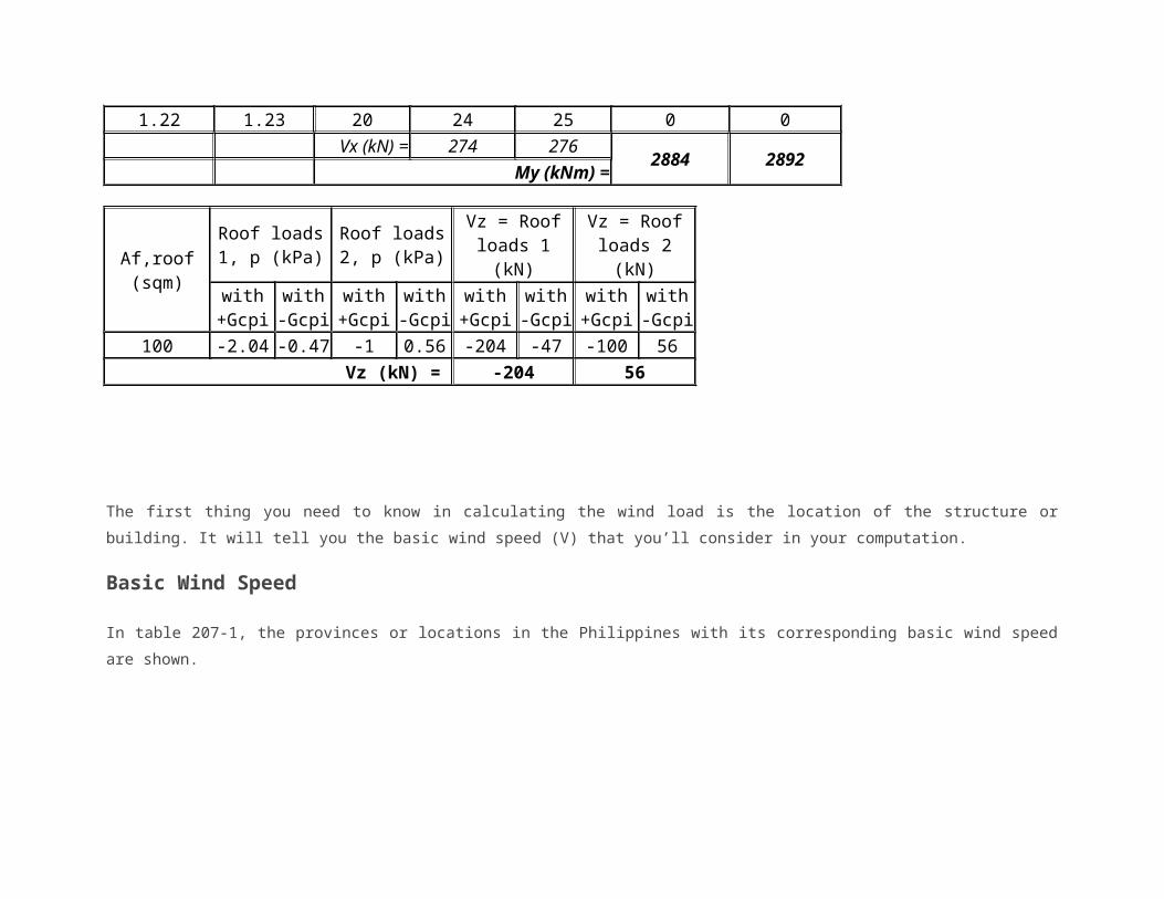
The first thing you need to know in calculating the wind load is the location of the structure or building. It will tell you the basic wind speed
(V) that you’ll consider in your computation.
Basic Wind Speed
In table 207-1, the provinces or locations in the Philippines with its corresponding basic wind speed are shown.
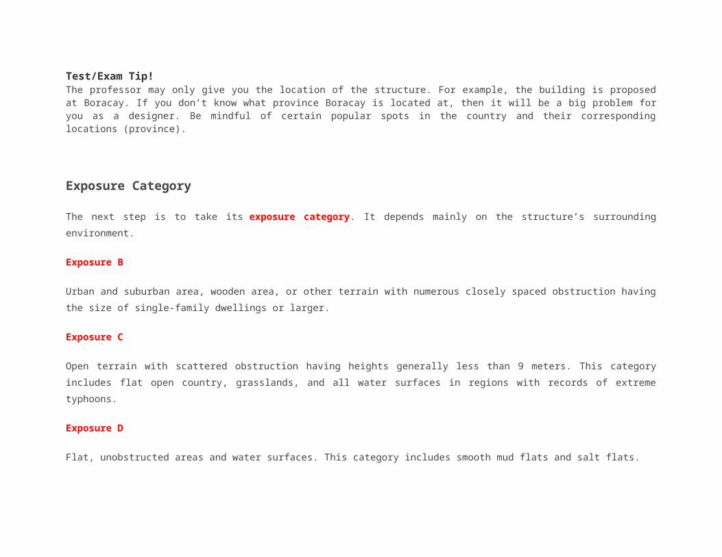
Test/Exam Tip!The professor may only give you the location of the structure. For example, the building is proposed at Boracay. If you don’t know what province Boracay is located at, then it will be a big problem for you as a designer. Be mindful of certain popular spots in the country and their corresponding locations (province).
Exposure Category
The next step is to take its exposure category. It depends mainly on the structure’s surrounding environment.
Exposure B
Urban and suburban area, wooden area, or other terrain with numerous closely spaced obstruction having the size of single-family
dwellings or larger.
Exposure C
Open terrain with scattered obstruction having heights generally less than 9 meters. This category includes flat open country, grasslands,
and all water surfaces in regions with records of extreme typhoons.
Exposure D
Flat, unobstructed areas and water surfaces. This category includes smooth mud flats and salt flats.
Importance Factor
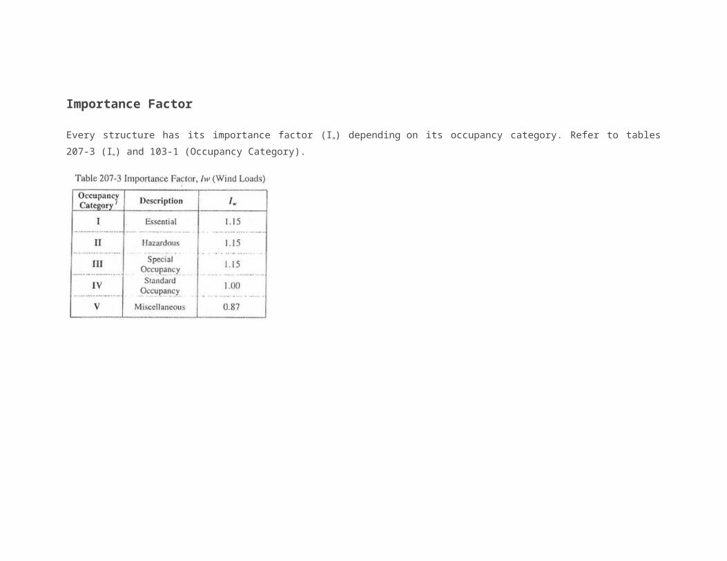
Every structure has its importance factor (Iw) depending on its occupancy category. Refer to tables 207-3 (Iw) and 103-1 (Occupancy
Category).
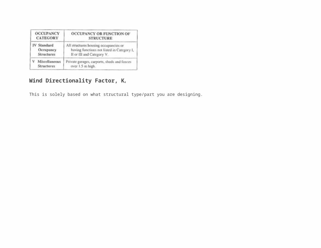
Wind Directionality Factor, Kd
This is solely based on what structural type/part you are designing.
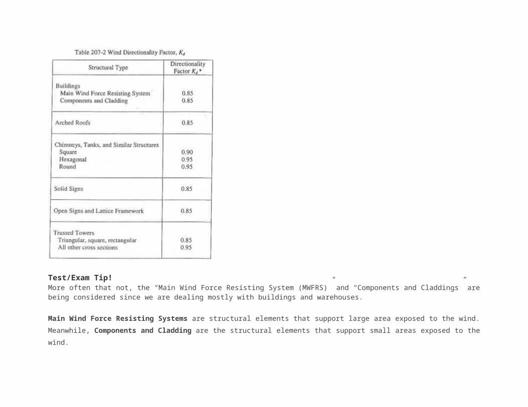
Test/Exam Tip!More often that not, the “Main Wind Force Resisting System (MWFRS)” and “Components and Claddings” are being considered since we are dealing mostly with buildings and warehouses.
Main Wind Force Resisting Systems are structural elements that support large area exposed to the wind. Meanwhile, Components and
Cladding are the structural elements that support small areas exposed to the wind.
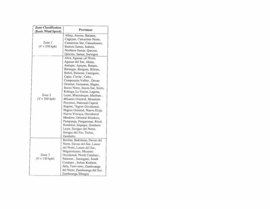
Exposure Coefficient, Kz/Kh
The velocity pressure exposure coefficients (Kz or Kh) goes larger as the height above the ground increases. All possible or
applicable values of “height above ground level” should be taken into consideration. When your structure lands in exposure B, consider two
cases (Case 1 and Case 2).
Interpolate the desired value if the height falls between two known values. Click here if you don’t know how to interpolate.
Topographic Factor, Kzt
For simplicity purposes, Kzt is usually equals to 1.
NOTE: For more detailed computation of Kzt, read 207.5.7.2 and 207.5.7.1.
Gust Factor, G
For stiff buildings and structures, use G = 0.85. (used most of the time)
For rigid buildings, read 207.5.8.1.
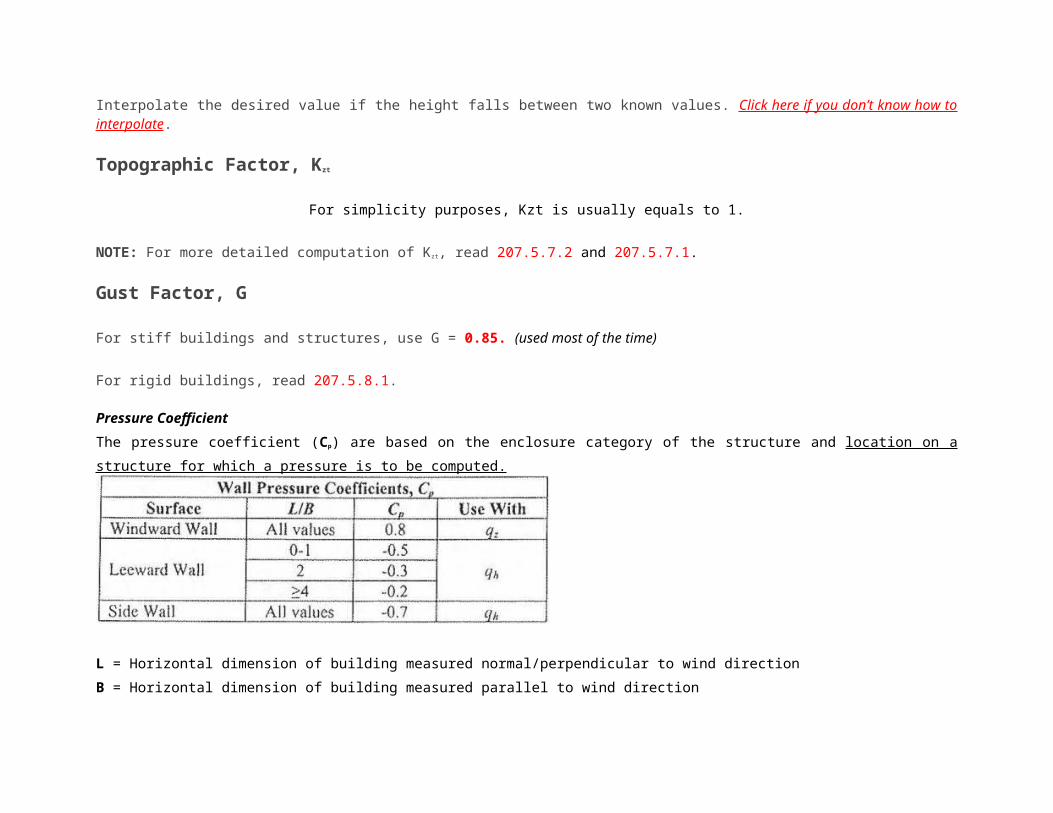
Pressure Coefficient
The pressure coefficient (Cp) are based on the enclosure category of the structure and location on a structure for which a pressure is to be
computed.
L = Horizontal dimension of building measured normal/perpendicular to wind direction
B = Horizontal dimension of building measured parallel to wind direction
H = Mean Roof Height (Height from the ground to the middle part of the roof)
*If angle is less than or equals to 10 degrees, use eave height (height of the structure excluding the roof)

For roof slopes greater than 80 degrees, use Cp=0.8
*Interpolate the desired coefficient if angle is between two known values.Windward, Leeward, Side Wall
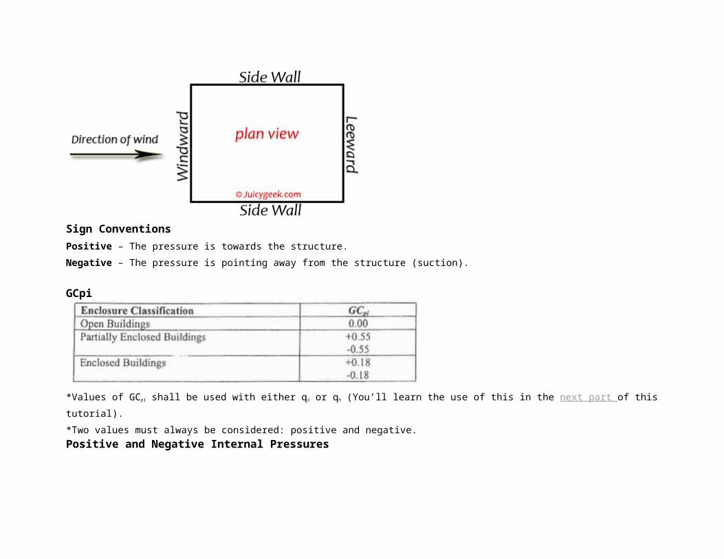
Sign Conventions
Positive – The pressure is towards the structure.
Negative – The pressure is pointing away from the structure (suction).
GCpi
*Values of GCpi shall be used with either qz or qh (You’ll learn the use of this in the next part of this tutorial).
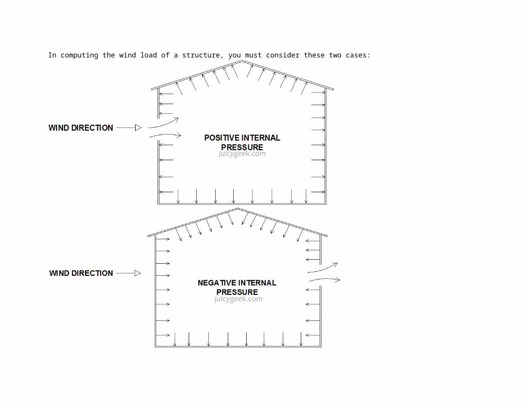
*Two values must always be considered: positive and negative.Positive and Negative Internal Pressures
In computing the wind load of a structure, you must consider these two cases:
Let’s now go straight to the computation process. We’ll be talking about the working formulas and how to apply it.
Take note that you MUST read part 1 and part 2 of this tutorial in order to fully understand this topic.
P = Wind pressure (this is what we want to get at the end)
P = qGCp – q(GCpi) – – – formula 1
q = 47.3 x 10⁻⁶ Kz Kzt Kd V2 Iw – – – formula 2
Eave height = height of wall (excluding the roof)
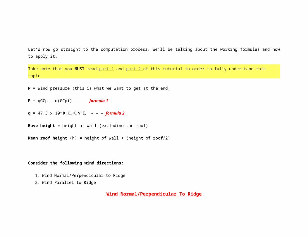
Mean roof height (h) = height of wall + (height of roof/2)
Consider the following wind directions:
1. Wind Normal/Perpendicular to Ridge
2. Wind Parallel to Ridge
Wind Normal/Perpendicular To Ridge
Windward Wall
P = qzGCp – qh(GCpi)
P = qzGCp – qh(-GCpi)
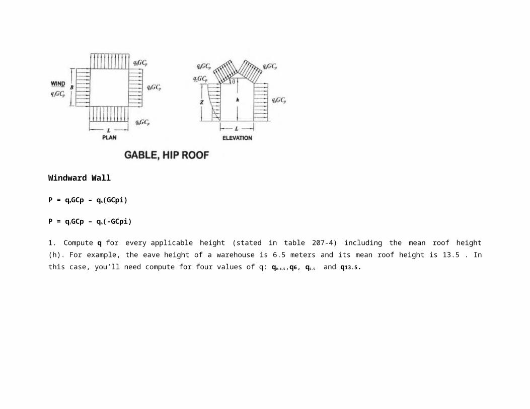
1. Compute q for every applicable height (stated in table 207-4) including the mean roof height (h). For example, the eave height of a
warehouse is 6.5 meters and its mean roof height is 13.5 . In this case, you’ll need compute for four values of q: q0-4.5,q6, q6.5 and q13.5.
2. The value of Cp for windward wall is 0.8.
3. G is usually equals to 0.85 unless otherwise stated.
4. Compute two values of P considering the positive and negative values of GCpi (i.e. +0.18 and -0.18).
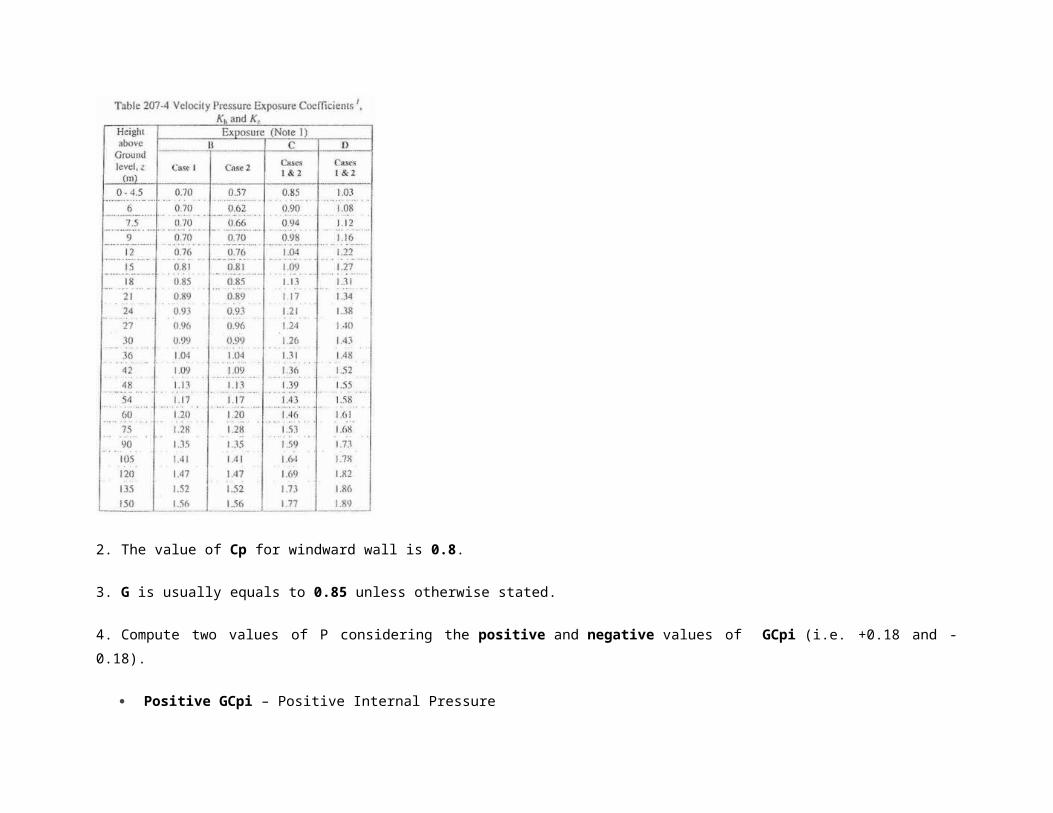
Positive GCpi – Positive Internal Pressure
Negative GCpi – Negative Internal Pressure
Leeward Wall
P = qhGCp – qh(GCpi)
P = qhGCp – qh(-GCpi)
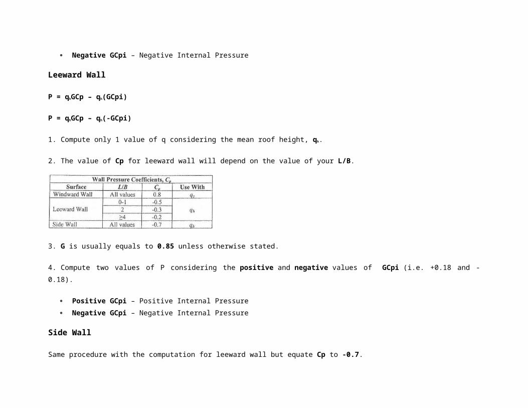
1. Compute only 1 value of q considering the mean roof height, qh.
2. The value of Cp for leeward wall will depend on the value of your L/B.
3. G is usually equals to 0.85 unless otherwise stated.
4. Compute two values of P considering the positive and negative values of GCpi (i.e. +0.18 and -0.18).
Positive GCpi – Positive Internal Pressure
Negative GCpi – Negative Internal Pressure
Side Wall
Same procedure with the computation for leeward wall but equate Cp to -0.7.
Roof
Use the table above for the values of Cp for both windward and leeward.
For enclosed buildings
P = qhGCp – qh(GCpi)
P = qhGCp – qh(-GCpi)
For partially enclosed buildings
Positive Internal Pressure:
P = qhGCp – qz(GCpi)
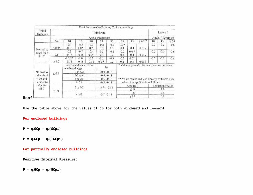
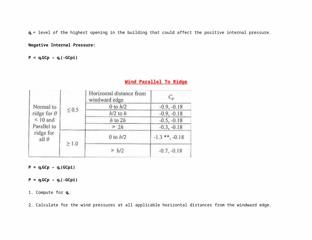
qz = level of the highest opening in the building that could affect the positive internal pressure.
Negative Internal Pressure:
P = qhGCp – qh(-GCpi)
Wind Parallel To Ridge
P = qhGCp – qh(GCpi)
P = qhGCp – qh(-GCpi)
1. Compute for qh.
2. Calculate for the wind pressures at all applicable horizontal distances from the windward edge.
3. As you have noticed, all the values are negative. It means all the forces will be suction or pointing away from the structure.
4. Wind pressures at the windward and leeward walls will be dealt the same way as above.
Given: The enclosed office building shown in Figure 7.4.1.1. The building is located in a region with a wind speed (3-sec gust) of 120 mph. The exposure is Exposure C. The building is on flat terrain.
Figure 7.4.1.1Building Definition
Wanted: The wind pressures applied to the surfaces and the net forces applied to the building.
Solution: To solve this problem, we need to independently look at two different wind directions, but first we will define a few parameters.
Determine critical elevations:
Mean Roof Height: h = 2*11' + (3/12)*25'/2 = 25.1 ft
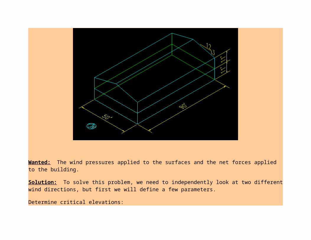
Mean 2nd Floor Height: h = 11' + 11'/2 = 16.5 ft Mean 1st Floor Height: h = 11'/2 = 5.5 ft
Compute the Velocity Pressures, qz = .00256 Kz Kzt Kd V2 I (ASCE 7-05 Equation 6-15)
Kzt = 1 (Flat Terrain) Kd = .85 (ASCE 7-05 Table 6-4, Buildings) I = 1.0 (ASCE 7-05 Table 6-1, Category II building) Kz = varies with elevation = 2.01(max(h,15)/900)(2/9.5), (ASCE 7-05 Tables 6-2 and 6-3)
h Kz qz
(ft) (psf)Roof 25.125 0.946 29.72nd flr 16.5 0.866 27.11st flr 5.5 0.849 26.6
Compute the Internal Pressures, qhGCpi:
GCpi = + 0.18 (ASCE 7-05 Figure 6-5) qh = 29.7 psf qhGCpi = + 5.34 psf
Determine the Gust Factor, G
G = 0.85 (ASCE 7-05, 6.5.8.1)
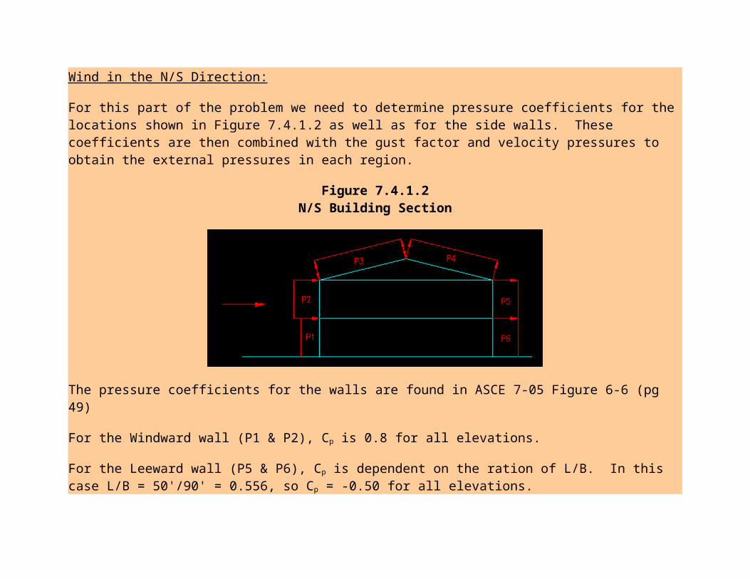
Wind in the N/S Direction:
For this part of the problem we need to determine pressure coefficients for the locations shown in Figure 7.4.1.2 as well as for the side walls. These coefficients are then combined with the gust factor and velocity pressures to obtain the external pressures in each region.
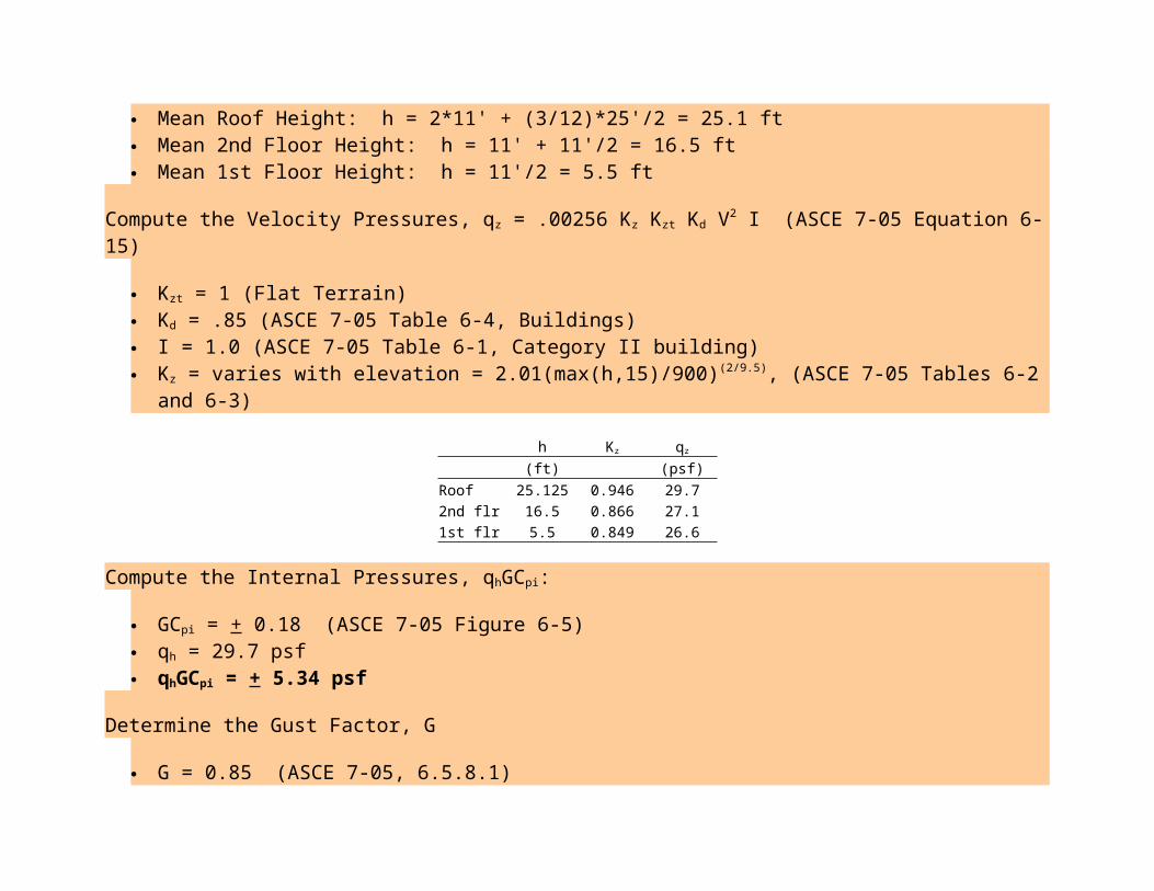
Figure 7.4.1.2N/S Building Section
The pressure coefficients for the walls are found in ASCE 7-05 Figure 6-6 (pg 49)
For the Windward wall (P1 & P2), Cp is 0.8 for all elevations.
For the Leeward wall (P5 & P6), Cp is dependent on the ration of L/B. In this case L/B = 50'/90' = 0.556, so Cp = -0.50 for all elevations.
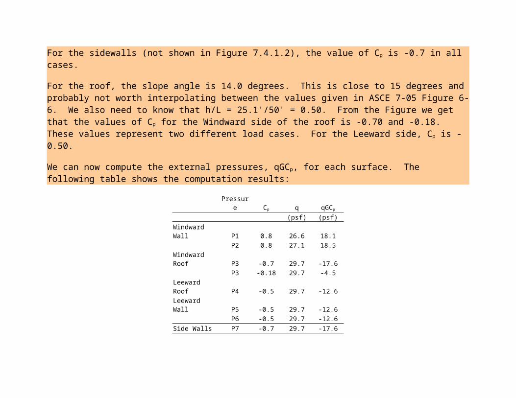
For the sidewalls (not shown in Figure 7.4.1.2), the value of Cp is -0.7 in all cases.
For the roof, the slope angle is 14.0 degrees. This is close to 15 degrees and probably not worth interpolating between the values given in ASCE 7-05 Figure 6-6. We also need to know that h/L = 25.1'/50' = 0.50. From the Figure we get that the values of Cp for the Windward side of the roof is -0.70 and -0.18. These values represent two different load cases. For the Leeward side, Cp is -0.50.
We can now compute the external pressures, qGCp, for each surface. The following table shows the computation results:
Pressure Cp q qGCp
(psf) (psf)Windward Wall P1 0.8 26.6 18.1
P2 0.8 27.1 18.5Windward Roof P3 -0.7 29.7 -17.6
P3 -0.18 29.7 -4.5Leeward Roof P4 -0.5 29.7 -12.6Leeward Wall P5 -0.5 29.7 -12.6 P6 -0.5 29.7 -12.6Side Walls P7 -0.7 29.7 -17.6
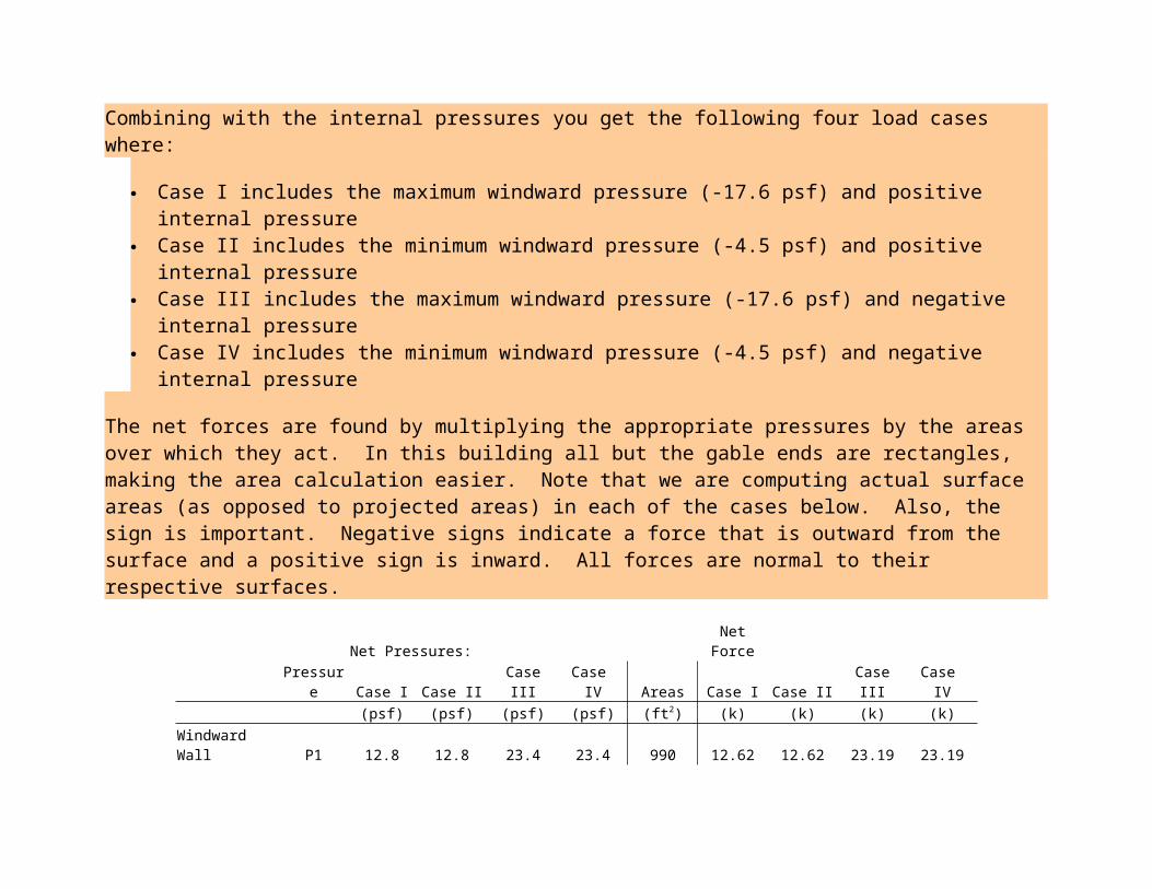
Combining with the internal pressures you get the following four load cases where:
Case I includes the maximum windward pressure (-17.6 psf) and positive internal pressure
Case II includes the minimum windward pressure (-4.5 psf) and positive internal pressure Case III includes the maximum windward pressure (-17.6 psf) and negative internal
pressure Case IV includes the minimum windward pressure (-4.5 psf) and negative internal
pressure
The net forces are found by multiplying the appropriate pressures by the areas over which they act. In this building all but the gable ends are rectangles, making the area calculation easier. Note that we are computing actual surface areas (as opposed to projected areas) in each of the cases below. Also, the sign is important. Negative signs indicate a force that is outward from the surface and a positive sign is inward. All forces are normal to their respective surfaces.
Net Pressures: Net Force Pressure Case I Case II Case III Case IV Areas Case I Case II Case III Case IV
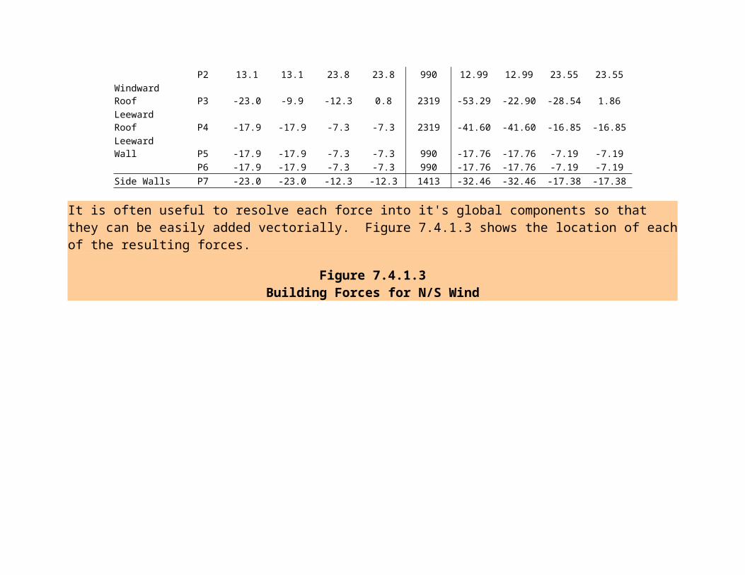
(psf) (psf) (psf) (psf) (ft2) (k) (k) (k) (k)Windward Wall P1 12.8 12.8 23.4 23.4 990 12.62 12.62 23.19 23.19
P2 13.1 13.1 23.8 23.8 990 12.99 12.99 23.55 23.55Windward Roof P3 -23.0 -9.9 -12.3 0.8 2319 -53.29 -22.90 -28.54 1.86Leeward Roof P4 -17.9 -17.9 -7.3 -7.3 2319 -41.60 -41.60 -16.85 -16.85Leeward Wall P5 -17.9 -17.9 -7.3 -7.3 990 -17.76 -17.76 -7.19 -7.19 P6 -17.9 -17.9 -7.3 -7.3 990 -17.76 -17.76 -7.19 -7.19Side Walls P7 -23.0 -23.0 -12.3 -12.3 1413 -32.46 -32.46 -17.38 -17.38
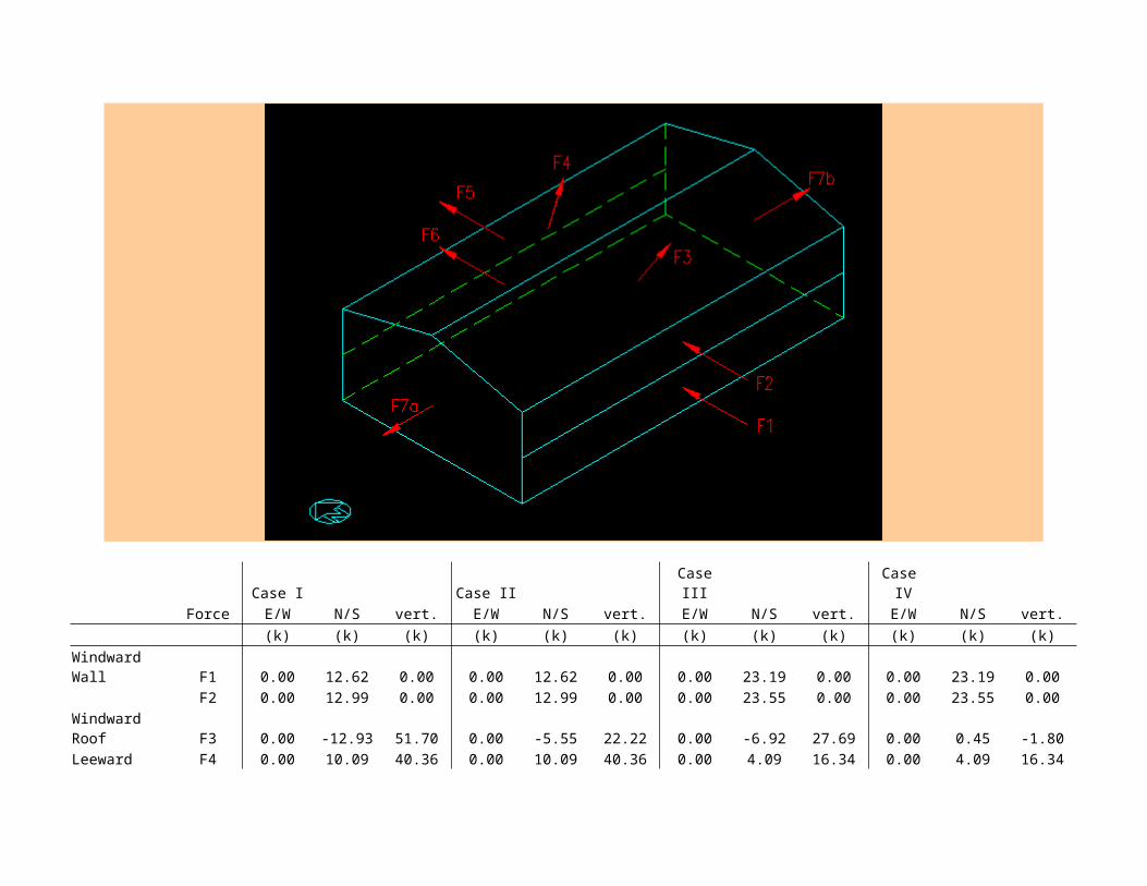
It is often useful to resolve each force into it's global components so that they can be easily added vectorially. Figure 7.4.1.3 shows the location of each of the resulting forces.
Figure 7.4.1.3Building Forces for N/S Wind
Case I Case II Case III Case IV Force E/W N/S vert. E/W N/S vert. E/W N/S vert. E/W N/S vert.
(k) (k) (k) (k) (k) (k) (k) (k) (k) (k) (k) (k)Windward Wall F1 0.00 12.62 0.00 0.00 12.62 0.00 0.00 23.19 0.00 0.00 23.19 0.00
F2 0.00 12.99 0.00 0.00 12.99 0.00 0.00 23.55 0.00 0.00 23.55 0.00Windward Roof F3 0.00 -12.93 51.70 0.00 -5.55 22.22 0.00 -6.92 27.69 0.00 0.45 -1.80Leeward Roof F4 0.00 10.09 40.36 0.00 10.09 40.36 0.00 4.09 16.34 0.00 4.09 16.34Leeward Wall F5 0.00 17.76 0.00 0.00 17.76 0.00 0.00 7.19 0.00 0.00 7.19 0.00
F6 0.00 17.76 0.00 0.00 17.76 0.00 0.00 7.19 0.00 0.00 7.19 0.00Side Walls F7a -32.46 0.00 0.00 -32.46 0.00 0.00 -17.38 0.00 0.00 -17.38 0.00 0.00 F7b 32.46 0.00 0.00 32.46 0.00 0.00 17.38 0.00 0.00 17.38 0.00 0.00
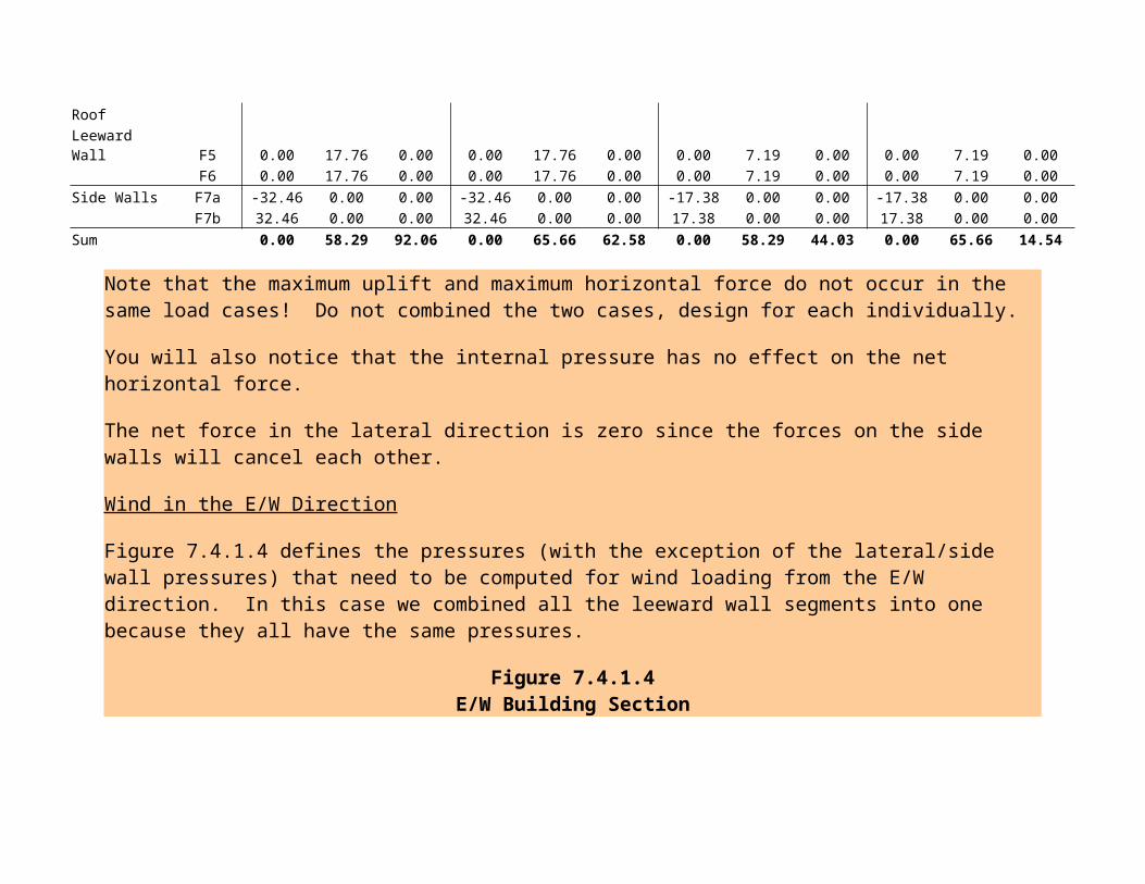
Sum 0.00 58.29 92.06 0.00 65.66 62.58 0.00 58.29 44.03 0.00 65.66 14.54
Note that the maximum uplift and maximum horizontal force do not occur in the same load cases! Do not combined the two cases, design for each individually.
You will also notice that the internal pressure has no effect on the net horizontal force.
The net force in the lateral direction is zero since the forces on the side walls will cancel each other.
Wind in the E/W Direction
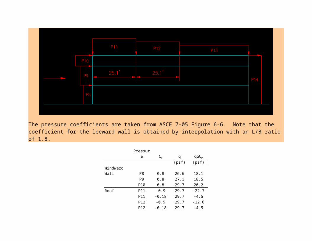
Figure 7.4.1.4 defines the pressures (with the exception of the lateral/side wall pressures) that need to be computed for wind loading from the E/W direction. In this case we combined all the leeward wall segments into one because they all have the same pressures.
Figure 7.4.1.4E/W Building Section
The pressure coefficients are taken from ASCE 7-05 Figure 6-6. Note that the coefficient for the leeward wall is obtained by interpolation with an L/B ratio of 1.8.
Pressure Cp q qGCp
(psf) (psf)Windward Wall P8 0.8 26.6 18.1
P9 0.8 27.1 18.5P10 0.8 29.7 20.2
Roof P11 -0.9 29.7 -22.7P11 -0.18 29.7 -4.5P12 -0.5 29.7 -12.6P12 -0.18 29.7 -4.5P13 -0.3 29.7 -7.6
P13 -0.18 29.7 -4.5Leeward Wall P14 -0.34 29.7 -8.6Side Walls P15 -0.7 29.7 -17.6
Note that some of the pressures are applied to differently oriented surfaces. When the same pressure is applied to a different surface, we have chosen to label on as "a" and the other as "b". See Figure 7.4.1.5 for force applications. Four cases are computed, based on combinations of maximum/minimum roof pressures and +internal pressures.
Figure 7.4.1.5Building Forces for E/W Wind
The net forces on each surface, in terms of direction relative the surface, are as follows:
Pressure Case I Case II Case III Case IV Area Case I Case II Case III Case IV
(psf) (psf) (psf) (psf) (ft2) (k) (k) (k) (k)Windward Wall P8 12.8 12.8 23.4 23.4 550 7.01 7.01 12.88 12.88
P9 13.1 13.1 23.8 23.8 550 7.21 7.21 13.09 13.09P10 14.8 14.8 25.5 25.5 156 2.32 2.32 3.98 3.98
Roof P11a -28.0 -9.9 -17.3 0.8 647 -18.12 -6.39 -11.22 0.52P11b -28.0 -9.9 -17.3 0.8 647 -18.12 -6.39 -11.22 0.52P12a -17.9 -9.9 -7.3 0.8 647 -11.60 -6.39 -4.70 0.52P12b -17.9 -9.9 -7.3 0.8 647 -11.60 -6.39 -4.70 0.52P13a -12.9 -9.9 -2.2 0.8 1026 -13.23 -10.13 -2.28 0.82
P13b -12.9 -9.9 -2.2 0.8 1026 -13.23 -10.13 -2.28 0.82Leeward Wall P14 -13.9 -13.9 -3.2 -3.2 1256 -17.47 -17.47 -4.06 -4.06Side Walls P15a -23.0 -23.0 -12.3 -12.3 1980 -45.50 -45.50 -24.36 -24.36 P15b -23.0 -23.0 -12.3 -12.3 1980 -45.50 -45.50 -24.36 -24.36
Restating the forces in terms of the global coordinate system we get:
Case I Case II Case III Case IV Pressure E/W N/S vert. E/W N/S vert. E/W N/S vert. E/W N/S vert.
(k) (k) (k) (k) (k) (k) (k) (k) (k) (k) (k) (k)Windward Wall F8 7.01 0.00 0.00 7.01 0.00 0.00 12.88 0.00 0.00 12.88 0.00 0.00
F9 7.21 0.00 0.00 7.21 0.00 0.00 13.09 0.00 0.00 13.09 0.00 0.00F10 2.32 0.00 0.00 2.32 0.00 0.00 3.98 0.00 0.00 3.98 0.00 0.00
Roof F11a 0.00 4.40 17.58 0.00 1.55 6.20 0.00 2.72 10.88 0.00 -0.13 -0.50F11b 0.00 -4.40 17.58 0.00 -1.55 6.20 0.00 -2.72 10.88 0.00 0.13 -0.50F12a 0.00 2.81 11.26 0.00 1.55 6.20 0.00 1.14 4.56 0.00 -0.13 -0.50F12b 0.00 -2.81 11.26 0.00 -1.55 6.20 0.00 -1.14 4.56 0.00 0.13 -0.50F13a 0.00 3.21 12.83 0.00 2.46 9.82 0.00 0.55 2.21 0.00 -0.20 -0.80
F13b 0.00 -3.21 12.83 0.00 -2.46 9.82 0.00 -0.55 2.21 0.00 0.20 -0.80Leeward Wall F14 17.47 0.00 0.00 17.47 0.00 0.00 4.06 0.00 0.00 4.06 0.00 0.00Side Walls F15a 0.00 45.50 0.00 0.00 45.50 0.00 0.00 24.36 0.00 0.00 24.36 0.00 F15b 0.00 -45.50 0.00 0.00 -45.50 0.00 0.00 -24.36 0.00 0.00 -24.36 0.00Sum 34.01 0.00 83.34 34.01 0.00 44.43 34.01 0.00 35.31 34.01 0.00 -3.60