Embed Size (px)
Citation preview

International Research Journal of Applied and Basic Sciences. Vol., 3 (8), 1726-1734, 2012
Available online at http:// www. irjabs.com ISSN 2251-838X ©2012
An experimental interface design for a single-link elastic manipulator system
M. Doosthoseini
1, M. H. Korayem
2*, A. M. Shafei
3, B. Kadkhodaei
4
1- M.Sc. Student of Mechatronic Engineering Department, Islamic Azad University, Science and Research
Branch, Tehran, Iran
2- Professor of Mechanical Engineering Department, Iran University of Science and Technology, Narmak, Tehran, Iran.
3- Ph.D. Candidate of Mechanical Engineering Department, Iran University of Science and Technology,
Tehran, Iran 4- M.Sc. Student of Mechatronic Engineering Department, Islamic Azad University, Science and Research
Branch, Tehran, Iran
*Corresponding Author Email: [email protected]
Abstract
The high speed vibration of a flexible robotic arm compared to the low speed of software and hardware interface between the computer and experimental setup is one of the most important obstacles for measuring and control of such a systems. In this paper, a combination of using high speed digital to analog convertor (DAC) components on an electrical interface board and using National Instrument’s LABVIEW software package is proposed as a solution for this problem. Dynamic modeling of the system is developed based on Gibbs-Appell (G-A) formulation and Assumed Mode Method (AMM). The accuracy and completeness of the dynamical model of the system is dependent on the number of modes used to describe the system. An experimental setup of a single-link elastic robotic arm is prepared and the electrical interface board works between this experimental setup, user and computer. The input data by the electrical interface board are the number of mode shapes up to 4 and the profile of the input torque via time. Then these data transferred to the manipulator system. Finally user can see the vibration of the elastic link in graphical interface environment and model validation carried out by comparing both experimental and theoretical results. Keywords: Elastic manipulator, Interface, Labview, Vibration, Gibbs-Appell
Introduction
Designing the interface for various systems is done based on different requirements. But creating the
interface between the user and machine is the main reason. The designed interface should contain all system components as much as possible, and completely govern the system performance, and allow the user to obtain sufficient knowledge of the system in the same simulated environment and can apply the desired changes to the system model.
Educational aspects are one of the extensive applications of simulation environments that are used in interfaces. Software packages provided in educational products for training various systems, devices and experimental set-ups, enable the user to have a laboratory and get familiar with various system components and work with the model of the system, and examine the effects of parameters' variations. (Marín et al., 2005) used Java programming and Tele-lab software program for creating an interface environment for a robotic arm. (Khaisongkram et al., 2002) designed a graphical simulator environment and the required interface for communicating with the device and controlling it using Matlab-GUI. (Hasanul and Basher, 2007) modeled a flexible manipulator and represented the results of the model. He used Euler-Bernoulli beam theory (EBBT) for extracting the equation of motion.
The problem of dynamic modeling of flexible links in robotic systems has been a major problem in recent years. Accurate modeling of the link is an essential step for successful controlling of such systems. It
Intl. Res. J. Appl. Basic. Sci. Vol., 3 (8), 1726-1734, 2012
1727
is well known that flexible multi-body systems have many applications in many practical engineering, such as aeronautics, aerospace and robotics. So, a good dynamic model for these kinds of robots is important in many engineering applications.
Finite Element Method (FEM) and Assume Mode Method (AMM) are two important approaches for modeling elastic robotic manipulators. In AMM, the link flexibility is usually represented by a truncated modal series, in terms of spatial mode Eigenfunctions and time-varying mode amplitudes. If the benefits associated with the lightness of flexible robotic manipulators are not to be sacrificed, accurate dynamical models have to be developed. To include the effects of shear and rotational inertia the assumption of Timoshenko beam theory (TBT) can be used. TBT and AMM have been used by (Loudini, 2010, Ouyang et al., 2007, and Zheng et al., 2002) for deriving the equation of motion of flexible robotic manipulators.
There are many choices for writing the governing equation of motion of elastic robotic manipulators. Motion equation by G-A formulation has been used the least for deriving the dynamic equations of robotics manipulators. In the field of robotics, more recent investigations can be found in the investigation of (Vossoughi et al., 2008) where G-A formulation is used for motion equations of snake-like robots; in the work of (Mata et al., 2002) where inverse and forward dynamics equations of motion of N-rigid links are presented in recursive form; and in the research of (Korayem and shafei 2009) where motion equations of elastic link manipulators are presented.
Most of the work in the field of elastic robotic manipulator confined to theoretical investigations. For validation the theoretical results by experimental test-bed it can be pointed out to the works of (Cannon, 1984, Rovner, 1987, and Shaheed and tokhi 2002) where in their investigations a setup for single link elastic robotic manipulator is prepared.
The main goal of this paper is designing an interface for a model of elastic single-link manipulator system that its equations have been extracted based on G-A method. The interface is designed with LABVIEW software. Therefore, in the following, kinematic and dynamic equations of manipulator robot with elastic link are described. Also the simulator and interface model is designed and the prepared experimental set-up is introduced and the results of interface connection with the system are also provided. Kinematics of a Single-Link Elastic Manipulator System
The single-link flexible manipulator system considered in this work is shown in Fig. 1, where XYZ and xyz represent the stationary and moving coordinate’s frames, respectively.
Figure 1. Single Link Elastic Robotic Manipulator
The position vector of arbitrary differential element Q with respect to the local reference system
xyz is shown by Q/or�
. The approach of modal analysis is used to incorporate the deflection of the link. So,
{ }T
Q/o wvu�r +=��
(1)
where { }T00�� =
� is the position vector of differential element Q with respect to o , when the elastic
link is undeformed; u , v and w are small displacements in ox , oy and oz directions, respectively. To
express these small displacements, the approach of assumed mode method is used as,
{ } ( ) ( )� ==
m
1i ii
T�rt�wvu
� (2)
Intl. Res. J. Appl. Basic. Sci. Vol., 3 (8), 1726-1734, 2012
1728
where { }T
iiii zyxr =�
is the Eigenfunction vector whose components ix , iy and iz are i -th
longitudinal and transverse mode shapes of the link; i� is the i -th time dependent modal generalized
coordinate of the link; and m is the number of modes used to define the deflection of the link.
The total transverse displacement of the centerline of differential element Q is due to bending and
shear. So the total slopes of the deflected centerline about oy and oz directions due to the bending and
shear deformation can be represented as
yy ��
w+=
∂
∂− ϕ (3)
zz ��
v+=
∂
∂ϕ (4)
where yϕ and zϕ are the slope of the deflected centerline due to shear and y� , z� are the slope of the
deflected centerline due to bending. Shear has no influence on rotating the differential element Q ; and this
differential element undertakes rotations only due to bending and torsion. So the rotation of this element in
ox , oy and oz directions can be considered as x� , y� and z� , respectively. These small angles can be
represented by truncated modal expansion as
{ } ( ) ( )��t����� i
m
1i i
T
zyx
��
� === (5)
where { }T
ziyixii ���� =�
is the Eigenfunction vector whose components xi� , yi� and zi� are i -th
rotational mode shapes of the link in ox , oy and oz directions, respectively.
Gibbs-Appell Method
In this section the system’s acceleration energy and its derivatives with respect to quasi-accelerations are developed for construction the G-A formulation. With the assumption of TBT, the acceleration energy of the system can be represented as
( )( ) ( )� ⋅+⋅=l
0
T
Q
T
Q d���J�2
1d�rr��
2
1S
������������ (6)
But with the assumption of EBBT only the first term of Eq. (6) should be preserved. Also ( )�� and ( )�J are
mass per unit length and mass moment of inertia matrix per unit length, respectively. Note that Qr��� and �
���
are
linear and angular acceleration of differential element Q . These two terms can be stated as,
( )Q/oQ/oQ/oQ/oQ r��r�r�2rr��������������� ××+×+×+= (7)
( ) ( )��t�� j
m
1j j
������
� == (8)
In above expressions, ��
and ���
are angular velocity and angular acceleration of the link, respectively; Also
Q/or��
and Q/or���
are velocity and acceleration of differential element Q with respect to the origin of the local
reference system, respectively. Dynamic Equations of Flexible Link Manipulator System
Motion equation of viscoelastic robotic manipulators will be completed by considering the generalized forces which are caused by the remaining external force terms. Let us assume that there is no external load on the links of the considered robotic manipulator. So, the generalized forces in the deflection equations will be zero. The generalized force in the joint equations is the torque � that applies to the joint. With this
assumption, the dynamic equations of motion in the G-A formulation will be completed as follows:
• The joint equations of motion
�q
V
q
D
q
S e =∂
∂+
∂
∂+
∂
∂
��� (9)
• The deflection equations of motion
Intl. Res. J. Appl. Basic. Sci. Vol., 3 (8), 1726-1734, 2012
1729
0�
V
�
D
�
S
j
e
jj
=∂
∂+
∂
∂+
∂
∂���
m,1,2,......j = (10)
Results
In this paper, a computer program called Virtual Instruments (VI), is developed using the LABVIEW
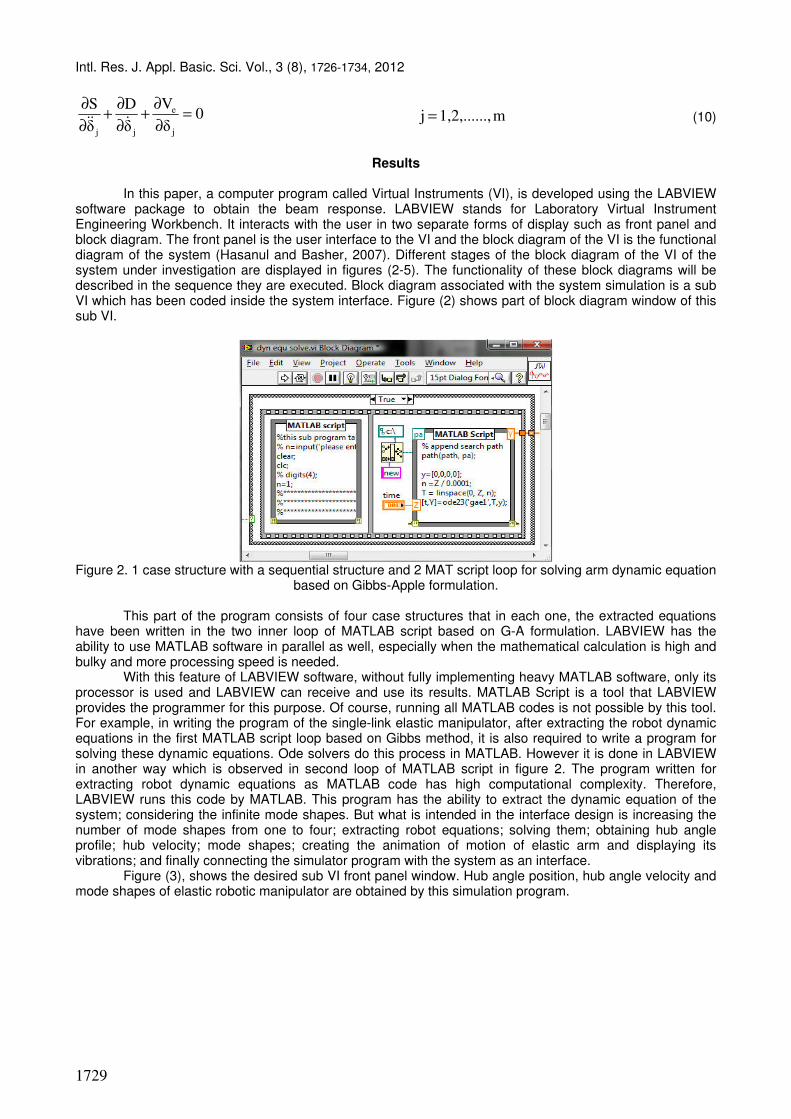
software package to obtain the beam response. LABVIEW stands for Laboratory Virtual Instrument Engineering Workbench. It interacts with the user in two separate forms of display such as front panel and block diagram. The front panel is the user interface to the VI and the block diagram of the VI is the functional diagram of the system (Hasanul and Basher, 2007). Different stages of the block diagram of the VI of the system under investigation are displayed in figures (2-5). The functionality of these block diagrams will be described in the sequence they are executed. Block diagram associated with the system simulation is a sub VI which has been coded inside the system interface. Figure (2) shows part of block diagram window of this sub VI.
Figure 2. 1 case structure with a sequential structure and 2 MAT script loop for solving arm dynamic equation
based on Gibbs-Apple formulation.
This part of the program consists of four case structures that in each one, the extracted equations have been written in the two inner loop of MATLAB script based on G-A formulation. LABVIEW has the ability to use MATLAB software in parallel as well, especially when the mathematical calculation is high and bulky and more processing speed is needed.
With this feature of LABVIEW software, without fully implementing heavy MATLAB software, only its processor is used and LABVIEW can receive and use its results. MATLAB Script is a tool that LABVIEW provides the programmer for this purpose. Of course, running all MATLAB codes is not possible by this tool. For example, in writing the program of the single-link elastic manipulator, after extracting the robot dynamic equations in the first MATLAB script loop based on Gibbs method, it is also required to write a program for solving these dynamic equations. Ode solvers do this process in MATLAB. However it is done in LABVIEW in another way which is observed in second loop of MATLAB script in figure 2. The program written for extracting robot dynamic equations as MATLAB code has high computational complexity. Therefore, LABVIEW runs this code by MATLAB. This program has the ability to extract the dynamic equation of the system; considering the infinite mode shapes. But what is intended in the interface design is increasing the number of mode shapes from one to four; extracting robot equations; solving them; obtaining hub angle profile; hub velocity; mode shapes; creating the animation of motion of elastic arm and displaying its vibrations; and finally connecting the simulator program with the system as an interface.
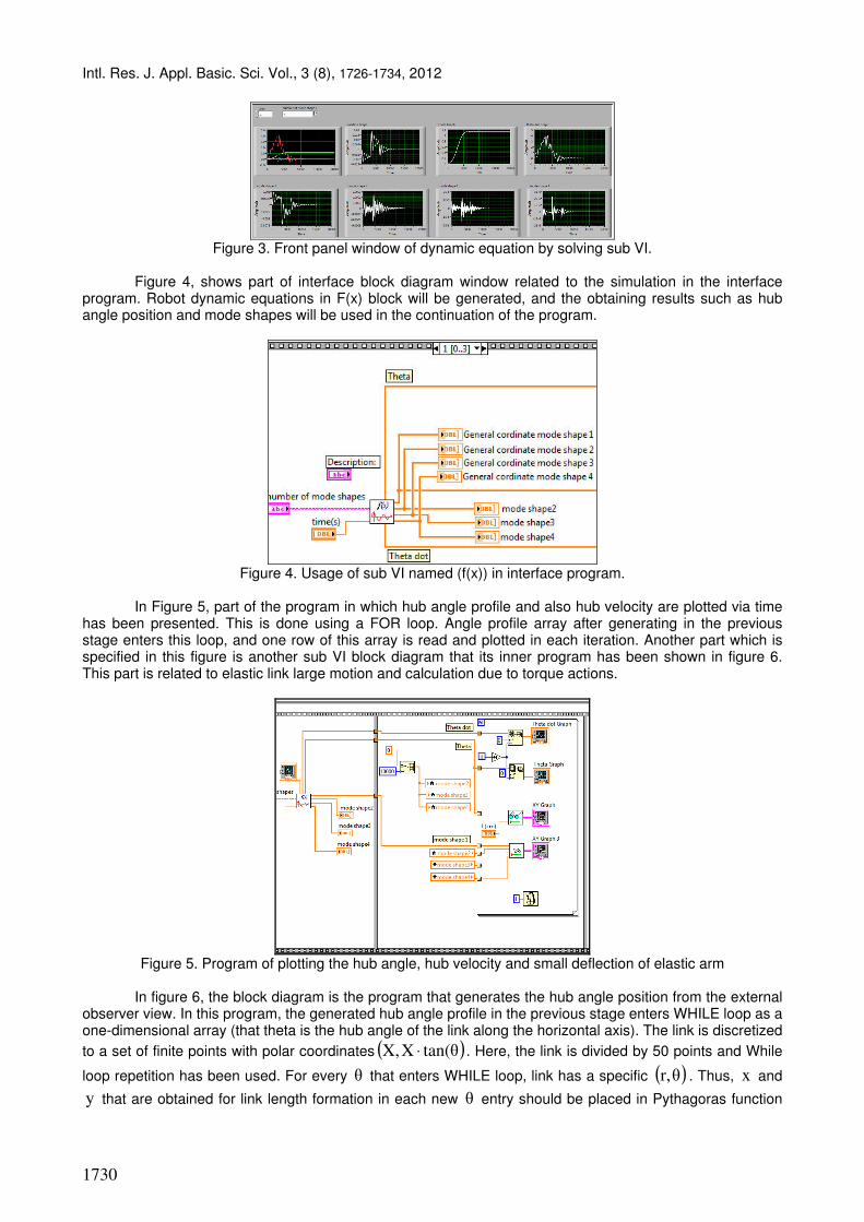
Figure (3), shows the desired sub VI front panel window. Hub angle position, hub angle velocity and mode shapes of elastic robotic manipulator are obtained by this simulation program.
Intl. Res. J. Appl. Basic. Sci. Vol., 3 (8), 1726-1734, 2012
1730
Figure 3. Front panel window of dynamic equation by solving sub VI.
Figure 4, shows part of interface block diagram window related to the simulation in the interface
program. Robot dynamic equations in F(x) block will be generated, and the obtaining results such as hub angle position and mode shapes will be used in the continuation of the program.
Figure 4. Usage of sub VI named (f(x)) in interface program.
In Figure 5, part of the program in which hub angle profile and also hub velocity are plotted via time
has been presented. This is done using a FOR loop. Angle profile array after generating in the previous stage enters this loop, and one row of this array is read and plotted in each iteration. Another part which is specified in this figure is another sub VI block diagram that its inner program has been shown in figure 6. This part is related to elastic link large motion and calculation due to torque actions.
Figure 5. Program of plotting the hub angle, hub velocity and small deflection of elastic arm
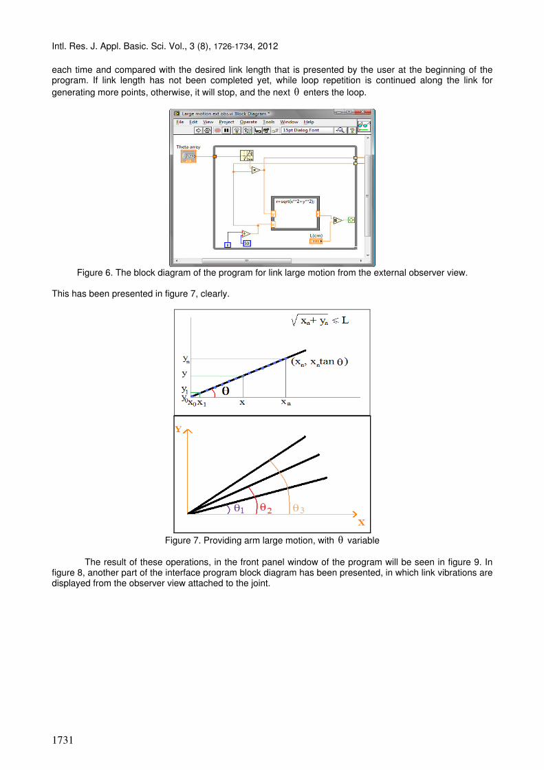
In figure 6, the block diagram is the program that generates the hub angle position from the external
observer view. In this program, the generated hub angle profile in the previous stage enters WHILE loop as a one-dimensional array (that theta is the hub angle of the link along the horizontal axis). The link is discretized
to a set of finite points with polar coordinates ( )tan(�XX, ⋅ . Here, the link is divided by 50 points and While
loop repetition has been used. For every � that enters WHILE loop, link has a specific ( )�r, . Thus, x and
y that are obtained for link length formation in each new � entry should be placed in Pythagoras function
Intl. Res. J. Appl. Basic. Sci. Vol., 3 (8), 1726-1734, 2012
1731
each time and compared with the desired link length that is presented by the user at the beginning of the program. If link length has not been completed yet, while loop repetition is continued along the link for
generating more points, otherwise, it will stop, and the next � enters the loop.
Figure 6. The block diagram of the program for link large motion from the external observer view.
This has been presented in figure 7, clearly.
Figure 7. Providing arm large motion, with � variable
The result of these operations, in the front panel window of the program will be seen in figure 9. In
figure 8, another part of the interface program block diagram has been presented, in which link vibrations are displayed from the observer view attached to the joint.
Intl. Res. J. Appl. Basic. Sci. Vol., 3 (8), 1726-1734, 2012
1732
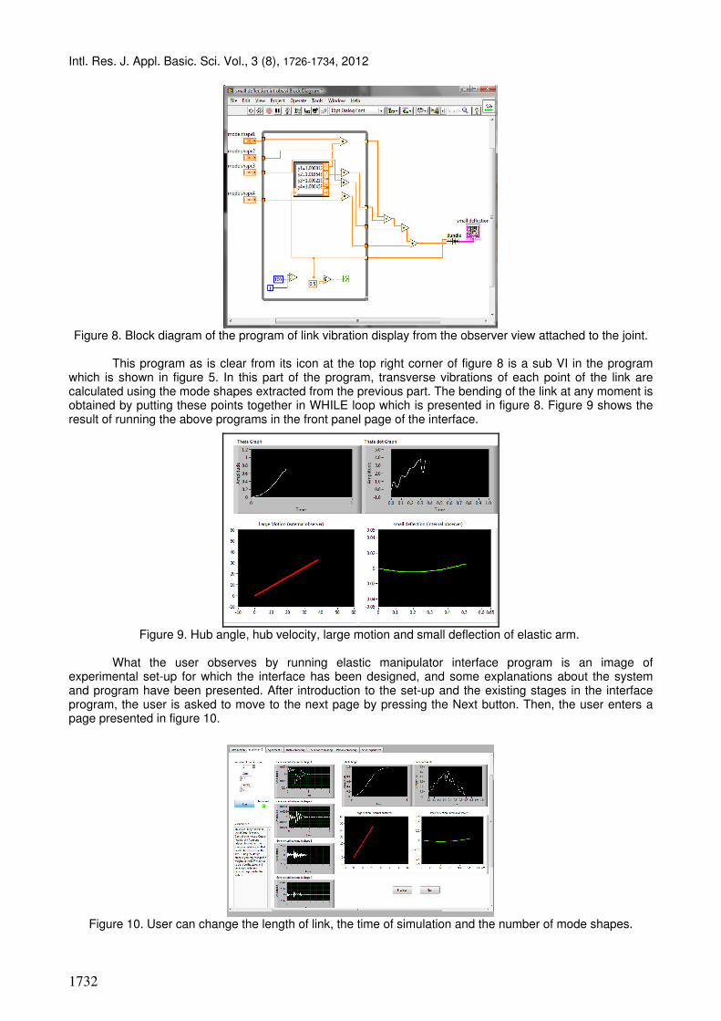
Figure 8. Block diagram of the program of link vibration display from the observer view attached to the joint.
This program as is clear from its icon at the top right corner of figure 8 is a sub VI in the program
which is shown in figure 5. In this part of the program, transverse vibrations of each point of the link are calculated using the mode shapes extracted from the previous part. The bending of the link at any moment is obtained by putting these points together in WHILE loop which is presented in figure 8. Figure 9 shows the result of running the above programs in the front panel page of the interface.
Figure 9. Hub angle, hub velocity, large motion and small deflection of elastic arm.
What the user observes by running elastic manipulator interface program is an image of
experimental set-up for which the interface has been designed, and some explanations about the system and program have been presented. After introduction to the set-up and the existing stages in the interface program, the user is asked to move to the next page by pressing the Next button. Then, the user enters a page presented in figure 10.
Figure 10. User can change the length of link, the time of simulation and the number of mode shapes.
Intl. Res. J. Appl. Basic. Sci. Vol., 3 (8), 1726-1734, 2012
1733
In the explanations of this page, the user will be asked to press Run button by determining the arbitrary values for the link length, time duration and number of mode shapes (one to four has been considered as the default in this program) and wait for generating robot dynamic equations and then the results of simulation.
Finally, time profile of mode shapes, link's hub angle, hub velocity, link's large motion from the external observer view and the link's small vibrations from the internal observer view will be displayed. The effect of increase in the link length and other parameters can be observed comparatively in the next pages of the program.
Eventually, there is the page of connecting to the system, in which the user set type of input torque from several default torques, then sends motion order through the serial port to the designed interface board. Experimental Set up Interface Section
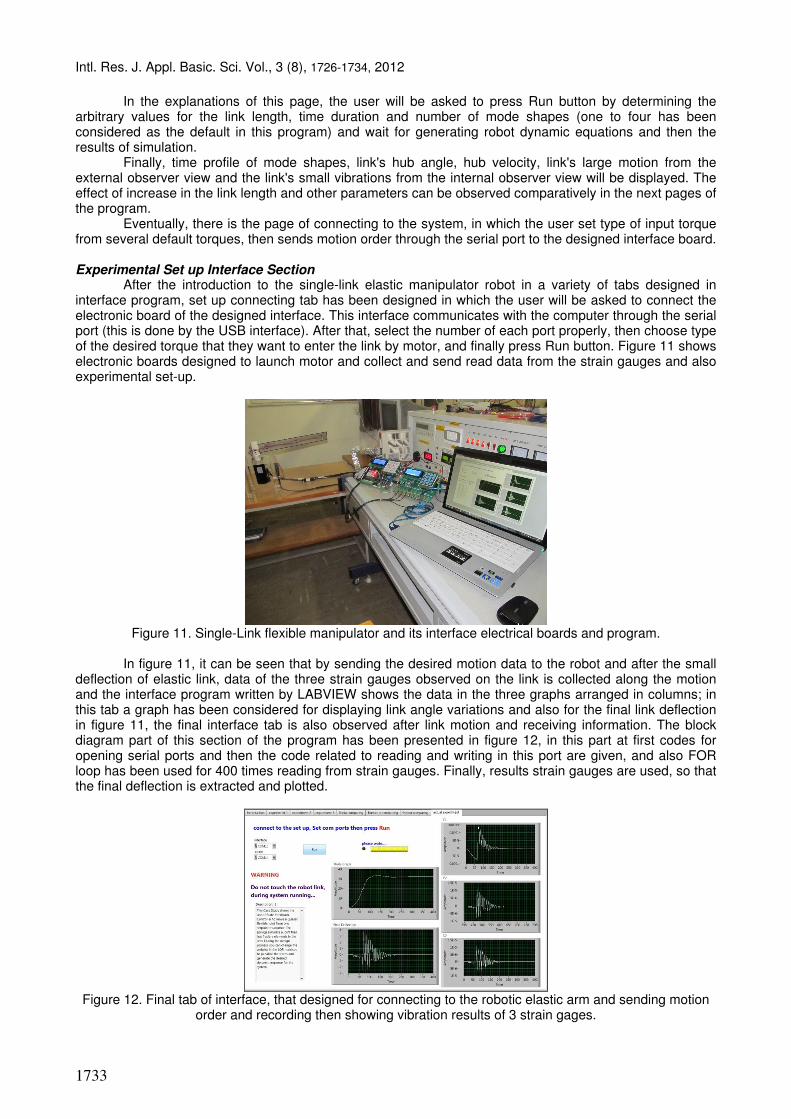
After the introduction to the single-link elastic manipulator robot in a variety of tabs designed in interface program, set up connecting tab has been designed in which the user will be asked to connect the electronic board of the designed interface. This interface communicates with the computer through the serial port (this is done by the USB interface). After that, select the number of each port properly, then choose type of the desired torque that they want to enter the link by motor, and finally press Run button. Figure 11 shows electronic boards designed to launch motor and collect and send read data from the strain gauges and also experimental set-up.
Figure 11. Single-Link flexible manipulator and its interface electrical boards and program.
In figure 11, it can be seen that by sending the desired motion data to the robot and after the small
deflection of elastic link, data of the three strain gauges observed on the link is collected along the motion and the interface program written by LABVIEW shows the data in the three graphs arranged in columns; in this tab a graph has been considered for displaying link angle variations and also for the final link deflection in figure 11, the final interface tab is also observed after link motion and receiving information. The block diagram part of this section of the program has been presented in figure 12, in this part at first codes for opening serial ports and then the code related to reading and writing in this port are given, and also FOR loop has been used for 400 times reading from strain gauges. Finally, results strain gauges are used, so that the final deflection is extracted and plotted.
Figure 12. Final tab of interface, that designed for connecting to the robotic elastic arm and sending motion
order and recording then showing vibration results of 3 strain gages.

Intl. Res. J. Appl. Basic. Sci. Vol., 3 (8), 1726-1734, 2012
1734
Figure 13. Block diagram of final tab of interface program, for connecting to the robot
Conclusions
In this paper, designing a research-educational software package for elastic robot was introduced by
LABVIEW software in which at first the link large motion and vibration motion are modeled, then the effect of link parameters variation such as length, thickness and the air damping, etc. are examined on the system response, at the end, interface creates a direct connection with set up, and the user can move elastic arm of the robot through sending torque order, and show results of strain gauges placed on the link for recording vibrations.
References Cannon RH, Schmitz E, 1984. Initial experiments on end-point control of a flexible one-link robot. The
International Journal of Robotics Research.3 (3): 62-75. Hasanul A, Basher 2007. Modeling and Simulation of Flexible Robot Manipulator with a Prismatic Joint. IEEE
SOUTHEASTCON. art. no. 4147428: 255-260. Khaisongkram W, BanjerdpongchaiD, 2002. MATLAB Based GUIs for Linear Controller Design via Convex
Optimization. Computer Applications in Engineering Education.11 (1): 13-24. Korayem MH, Shafei AM, 2009. Motion Equations Proper for Forward Dynamic of Robotic manipulators with
flexible links by using Recursive Gibbs-Appell Formulation. Scientia Iranica Transaction B-mechanical engineering.16 (6): 479-495.
Loudini M, 2010. Elastic link robot dynamics modeling based on beam theories. International Review on Modelling and Simulations, 3 (6): 1298-1307.
Marín R, Sanz PJ, Nebot P, Wirz R, 2005. A Multimodal Interface to Control a Robot Arm via the Web: A Case Study on Remote Programming. IEEE Transactions on Industrial Electronics, 52 (6): 1506-1520.
Mata V, Provenzano S, Cuadrado J.I, Valero F, 2002. Serial-robot dynamics algorithms for moderately large number of joints. Mechanism and machine Theory, No. 37: 739-755.
Ouyang H, Wang M, 2007. A dynamic model for a rotating beam subjected to axially moving forces. Journal of Sound and Vibration. 308 (3-5): 674-682.
Rovner DM, Cannon RH, 1987. Experiments toward on-line identification and control of a very flexible one-link manipulator. The International Journal of Robotics Research.6 (4): 3–19.
Shaheed M.H, Tokhi M.O, 2002. Dynamic modelling of a single-link flexible manipulator: parametric and non-parametric approaches.Robotica. No. 20: 93–109.
Vossoughi G, Pendar H, Heidari Z, Mohammadi S,2008. Assisted Passive Snake-Like Robots: Conception and Dynamic Modeling using Gibbs-Appell Method.Robotica, 26 (3): 267-276.
Zheng-You Z, Gen-Guo L, Chang-Jun C, 2002. Quasi-static and dynamical analysis for viscoelastic Timoshenko beam with fractional derivative constitutive relation. Applied Mathematics and Mechanics (English Edition).23 (1): 1-12.


![Cis TelePresenCo Ce isDn link...ISDN PRI Interface 1 testShutdown ISDN BRI Interface [1..4] testLoopmode ISDN BRI Interface [1..4] testPattern Cisco telePresence ISDN Link Administrator](https://img.pdfslide.net/doc/110x75/6131c5191ecc51586944f1c2/cis-telepresenco-ce-isdn-link-isdn-pri-interface-1-testshutdown-isdn-bri-interface.jpg)