Embed Size (px)
Citation preview

Purdue University Purdue University
Purdue e-Pubs Purdue e-Pubs
CTRC Research Publications Cooling Technologies Research Center
2021
An experimental investigation of the effect of thermal coupling An experimental investigation of the effect of thermal coupling
between parallel microchannels undergoing boiling on the between parallel microchannels undergoing boiling on the
Ledinegg instability-induced flow maldistribution Ledinegg instability-induced flow maldistribution
A. Miglani Purdue University
J. A. Weibel Purdue University, [email protected]
S V. Garimella University of Vermont, [email protected]
Follow this and additional works at: https://docs.lib.purdue.edu/coolingpubs
Miglani, A.; Weibel, J. A.; and Garimella, S V., "An experimental investigation of the effect of thermal coupling between parallel microchannels undergoing boiling on the Ledinegg instability-induced flow maldistribution" (2021). CTRC Research Publications. Paper 374. http://dx.doi.org/https://doi.org/10.1016/j.ijmultiphaseflow.2020.103536
This document has been made available through Purdue e-Pubs, a service of the Purdue University Libraries. Please contact [email protected] for additional information.
Corresponding author: [email protected]
**Currently President, University of Vermont
An experimental investigation of the effect of thermal coupling
between parallel microchannels undergoing boiling on the Ledinegg
instability-induced flow maldistribution
Ankur Miglania,b, Justin A. Weibela* and Suresh V. Garimellaa**
Abstract
Two-phase flow boiling is susceptible to the Ledinegg instability, which can result in non-uniform
flow distribution between parallel channels and thereby adversely impact the heat transfer
performance. This study experimentally assesses the effect of thermal coupling between the
parallel channels on flow maldistribution caused by the Ledinegg instability and compares the
results to our prior theoretical predictions. A system with two parallel microchannels is
investigated using water as the working fluid. The channels are hydrodynamically connected via
common inlet/outlet plenums and supplied with a constant total flow rate. The channels are
uniformly subjected to the same input power (which is increased in steps). Two separate
configurations are evaluated to assess drastically different levels of thermal coupling between the
channels, namely thermally isolated and thermally coupled channels. Synchronized measurements
of the flow rate in each individual channel, wall temperature, and pressure drop are performed
along with flow visualization to compare the thermal-hydraulic characteristics of these two
configurations. Thermal coupling is shown to reduce the wall temperature difference between the
channels and dampen flow maldistribution. Specifically, the range of input power over which flow
aSchool of Mechanical Engineering, Purdue University, West Lafayette, IN 47907 USA
bDepartment of Mechanical Engineering, Indian Institute of Technology, Indore, Madhya Pradesh 453552, India
2
maldistribution occurs is noticeably smaller and the maximum severity of flow maldistribution is
reduced in thermally coupled channels. The data provide a quantitative account of the effect of
lateral thermal coupling in moderating flow maldistribution, which is corroborated by comparison
to predictions from our two-phase flow distribution model. This combined experimental and
theoretical evidence demonstrates that, under extreme conditions when one channel is significantly
starved of flow rate and risks dryout, channel-to-channel thermal coupling can redistribute the heat
load from the flow-starved channel to the channel with excess flow. Due to such a possibility of
heat redistribution, the coupled channels are significantly less prone to flow maldistribution
compared to thermally isolated channels.
Keywords: Flow boiling; Ledinegg instability; maldistribution; parallel microchannels; thermal
coupling
Nomenclature
𝐴𝑤𝑎𝑙𝑙 total area of the walls of a single channel (2𝐻𝑐𝐿ℎ + 𝑊𝑐)
𝐴𝑏 cross-sectional area of the channel block (𝐻𝑏𝑊𝑏 − 𝐻𝑐𝑊𝑐)
𝐶𝑙𝑎𝑡 lateral thermal conductance
𝐻 height
𝐼 electric current
𝑘 thermal conductivity
𝐿 length
𝑃 power applied to each channel block
𝑃𝑖𝑛 heating power going into the channel
𝑃𝑙𝑜𝑠𝑠 power loss to ambient
𝑃𝑇 total power applied to the test section (2𝑃)
𝑃𝑇,𝑖𝑛 total power going into the channels (2𝑃𝑖𝑛)
𝑝𝑜𝑢𝑡 outlet pressure

3
∆𝑝𝑢ℎ pressure drop across the unheated channel length
∆𝑝ℎ pressure drop across the heated channel length
∆𝑝𝑜 overall pressure drop across the channels
𝑄 volumetric flow rate
𝑞𝑖𝑛" heat flux into the channel (𝑞𝑖𝑛
" = 𝑃𝑖𝑛 𝐴𝑤𝑎𝑙𝑙⁄ )
𝑆 pitch
𝑇 temperature
𝑇𝑓𝑙,𝑖𝑛 inlet fluid temperature
𝑇𝑓𝑙,𝑜𝑢𝑡 outlet fluid temperature
𝑇𝑠𝑎𝑡 saturation fluid temperature
𝑇𝑤𝑎𝑙𝑙,𝑖 wall temperature of the 𝑖𝑡ℎ channel
𝑉 voltage
𝑊 width
𝑦 vertical coordinate
𝑧 streamwise coordinate
Subscripts
𝑎𝑖𝑟 air gap
𝑏 channel block
𝑐 channel
𝑒𝑥𝑝 experiment
ℎ heated
𝑖 channel index (𝑖 = 1 or 2)
𝑚𝑜𝑑 model
wall channel wall
Greek Letters
𝜀𝑖 fraction of the total flow rate going into channel i (𝑄𝑖 𝑄𝑇⁄ )

4
1. Introduction
Over the last three decades, microscale two-phase heat sinks and cold plates have been
explored for low-pumping-power cooling of power-dense electronics in applications such as data
centers [1-2], traction inverters of hybrid and electric vehicles [3-4], and radars [5]. The coolant
flow is typically routed through multiple parallel channels to maximize the heat transfer area. Such
two-phase flow cooling strategies are attractive because they improve the heat transfer
performance and reduce the working temperatures and temperature gradients by utilizing the latent
heat of vaporization, while requiring a lower coolant flow rate (compared to single-phase cooling).
However, boiling flows are inherently prone to instabilities which may adversely impact the heat
sink performance, and in some cases, even lead to a premature dry-out at heat fluxes lower than
the predicted critical heat flux (CHF) [6, 7]. Flow boiling instabilities are commonly categorized
as either dynamic or static instabilities [8-12]. Static instabilities, the focus of the current work,
occur when a small disturbance causes the system to suddenly transition to a new stable operating
point that is significantly different from the initial condition.
One static instability of significant interest is the Ledinegg instability [13] because it
induces flow maldistribution even under steady and uniform heating conditions. The Ledinegg
instability is a consequence of the non-monotonic channel demand curve (channel pressure drop
versus flow rate) and the supply pump curve in flow boiling systems. For a single channel, the
Ledinegg instability occurs when the slope of the supply pump curve is greater than that of the
channel demand curve and is characterized by a drastic reduction in the flow through the channel.
In a system with multiple parallel channels, the Ledinegg instability results in non-uniform flow
distribution between the channels. This is detrimental to heat sink performance because the
channels that are starved of flow relative to a uniform flow distribution may undergo dry-out. This
5
may trigger an apparent premature critical heat flux and limit the heat sink performance
predictability. Several methods have been proposed to dampen the flow maldistribution caused by
the Ledinegg instability, including inlet orifices and throttle valves [7, 14-15], active control of the
flow at the channel inlet through pumps and valves [16-18], and increasing the system pressure
[19]. However, these measures have an associated penalty of significantly increasing either the
system complexity or pressure drop (i.e., pumping power), thereby reducing the attractiveness of
two-phase heat sinks.
Several studies have characterized the flow maldistribution caused by the Ledinegg
instability. For instance, Akagawa et al. [20] investigated the flow maldistribution in multiple large
evaporator tubes (4 mm inner diameter; 40 m long). They obtained the demand curves for each
tube undergoing flow boiling and measured the flow rate distribution in a system with up to three
parallel tubes. It was demonstrated that the flow rate distribution in a multiple-tube system could
be estimated from the individual tube load curves. A modeling approach was developed to generate
a stability criterion by performing a Laplace transformation on the linearized momentum and
continuity equations for a system of parallel tubes, which yielded predictions consistent with their
experimental observations. Minzer et al. [21-22] investigated the flow distribution behavior in a
system with two heated parallel tubes (5 mm inner diameter; 6 m long). In these studies, the flow
rate measurements in individual tubes were obtained either through a pressure drop element (such
as an inlet restrictor, throttle valve, or flow meter) at the inlet of each channel or by collecting and
measuring the fluid volume exiting each channel. Notably, these studies also focused on large
separate tubes that are thermally isolated from each other, differing drastically from parallel
microchannel heat sinks used in electronics cooling applications, where channels are thermally
connected via a common substrate. Kingston et al. [23] experimentally investigated the

6
temperature non-uniformity caused by the Ledinegg instability in two thermally isolated, parallel
channels. Two cylindrical microchannels were uniformly subjected to the same power which was
increased in steps. With increasing power, when boiling occurred in one of the channels, the
Ledinegg instability triggered a temperature difference between the channels, which grew with
increasing power. The wall temperature and heat flux measurements were used to attribute the
observed behavior to the increasing severity of flow maldistribution between the channels. In our
recent study [24], we extended the approach presented in Ref. [23] by enabling a direct
measurement of the flow rate in each channel synchronized with the wall temperature and overall
pressure drop measurements to characterize the thermal and hydrodynamic effects of the Ledinegg
instability on thermally isolated channels. It was demonstrated that once flow maldistribution is
triggered by the Ledinegg instability, its severity grows with increasing power. This causes the
temperature of the flow-starved channel to increase continuously and the wall temperature
difference to grow with increasing power.
The severity of the flow maldistribution encountered in the studies reviewed above, which
considered a special case of thermally isolated parallel channels, is exaggerated compared to
experimental experience [25-28]. In actual microchannel heat sinks, however, the high thermal
conductivity of the fins and substrate results in strong lateral thermal coupling between
neighboring channels and allows for heat redistribution. This contrasts with most past studies on
the Ledinegg instability which used parallel pipes that are physically isolated from one another
[20-22].
A few studies have considered the effect of lateral thermal coupling on dampening the flow
maldistribution between parallel channels. Flynn et al. [25, 29] studied the thermal implications of
flow maldistribution between two parallel microchannels (etched in a silicon substrate) that were

7
either thermally coupled or thermally isolated. The heat input to each of the channels could be
varied independently and they were tested under both uniform and non-uniform heating conditions.
In the thermally isolated configuration, the channel subjected to a higher heat load underwent
boiling, while the other channel remained a single-phase liquid, leading to a noticeable channel-
to-channel temperature difference. Based on the observed temperature difference it was inferred
that flow maldistribution existed between the channels (as no direct measurement could be made
of the flow rate to each channel). In contrast, in the thermally coupled configuration, the flow in
both channels either remained a single-phase liquid or they both underwent boiling, even under
severe non-uniform heating. No significant wall temperature difference existed between the
channels, from which it was inferred that the flow distribution was uniform. Van Oevelen et al.
[30] were the first to theroretically investigate the effect of channel-to-channel thermal coupling
on flow distribution by accounting for axial and lateral wall conduction. They predicted that
increasing the strength of thermal coupling between the channels reduced the severity of flow
maldistribution via redistribution of heat from the flow-starved channel to the adjacent channels
with excess flow. Additionally, they identified a threshold heat flux below which the flow
maldistribution can be completely suppressed by this mechanism. This threshold heat flux
increases with an increase in thermal coupling and eventually asymptotes to a constant value in
the limit of very strong thermal coupling. These past efforts have identified the critical implications
of channel-to-channel thermal coupling on determining the Ledinegg-instability-induced flow
maldistribution in boiling parallel microchannels. However, experimental characterization of the
Ledinegg instability in thermally coupled channels has been lacking. In particular, the
measurement of flow rates in individual channels is needed to corroborate past theoretical
predictions. Consideration of the role of lateral thermal coupling in moderating flow

8
maldistribution will allow other mitigation techniques such as inlet throttling to be more sparingly
employed.
In this study, the experiments are designed to incorporate and study the effect of thermal
wall conductance on the flow distribution between two parallel microchannels undergoing boiling.
Experiments are performed under thermally isolated and thermally coupled conditions that
represent two extreme levels of thermal connectivity between the channels. Comparison between
the thermally isolated case and the thermally coupled case allows any change in the flow
distribution behavior, as well as the measured wall temperature difference and overall pressure
drop, to be attributed solely to the mechanism of heat transfer between the channels. Synchronized
measurements of the wall temperature, the flow rate in each channel, and the overall pressure drop
are presented to illustrate the differences between the isolated and coupled cases. The experiments
demonstrate that channel-to-channel thermal coupling (via heat conduction through the wall) plays
a critical role in moderating flow maldistribution between the channels by allowing redistribution
of the heat flux. In the last section, these experimental results are directly compared with
predictions from our two-phase flow distribution model [30, 31] and are shown to have an excellent
match, thereby confirming the mitigating influence of thermal coupling on flow maldistribution.
2. Experimental methods
2.1. Test facility
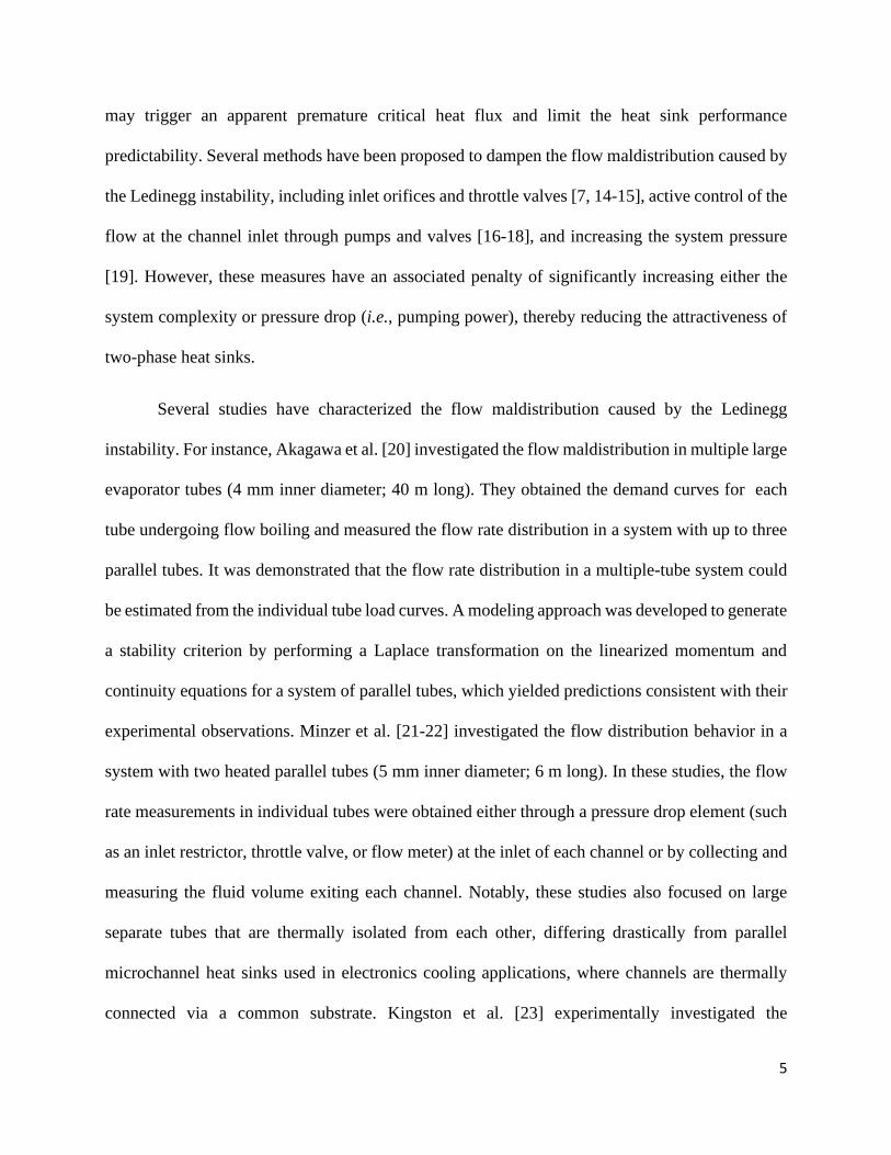
A photograph of the custom-built experimental facility for investigating the effect of
thermal coupling between boiling parallel microchannels on the flow maldistribution caused by
the Ledinegg instability is shown in Fig. 1. The flow loop components, aside from the test section,
are identical to the facility presented in Ref. [24] and are summarized here. A magnetically-

9
coupled gear pump (GA V21, Micropump) circulates the degassed DI water through a closed loop.
The water flow rate is measured using a liquid flow meter (LC-10CCM, Alicat; accuracy of ±1%
full scale), and tuned to a constant set-point value by controlling a metering valve placed in the
recirculation line. The fluid temperature at the test section inlet is controlled using an inline heater
(120 V AC, 468 W). The inlet and outlet fluid temperatures are measured using calibrated T-
type thermocouples (TMTSS-020E-6, Omega Engineering; ±0.3°C) located immediately
upstream and downstream of the test section, respectively.
Pressure drop across the test-section (∆𝑝𝑜) is measured with a differential pressure
transducer (PX154-005DI Wet-Wet, Omega; 0 - 1250 Pa; ±2% full scale). The pressure sensing
ports for the overall pressure drop measurement are in the test-section inlet and outlet plenums.
Fluid exiting the test section returns to the reservoir and then enters a liquid-to-air heat exchanger
where it is cooled before entering the pump inlet. The reservoir contains excess fluid and has an
adjustable volume which allows the system pressure to be set to a desired value of 104.4 kPa,
which is measured at the test-section outlet using an absolute pressure transducer (PX309-
030G5V, Omega Engineering; ±1%). The entire experimental facility is mounted on a vibration-
isolated optical table (VIS3672-PG2-325A, Newport Corp.) to ensure that external vibrations are
not transmitted to the components.
10
Fig. 1. A photograph of the experimental test facility with key components labeled. [1.5
columns]
2.2. Test section
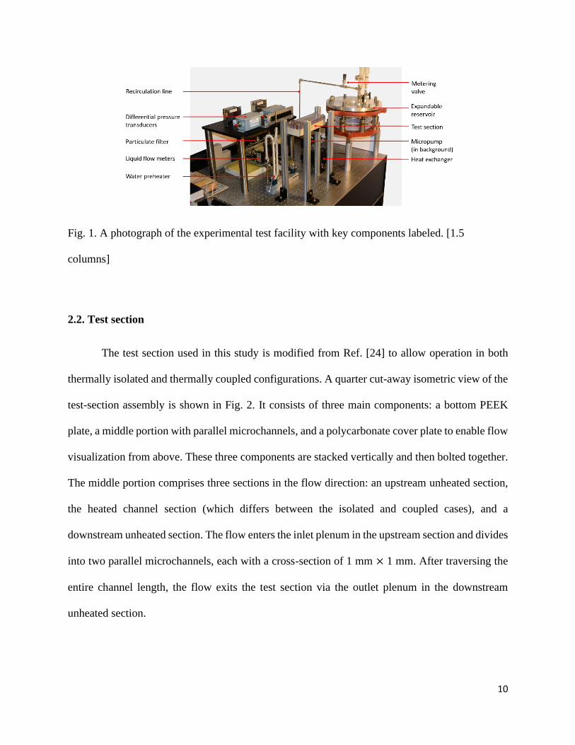
The test section used in this study is modified from Ref. [24] to allow operation in both
thermally isolated and thermally coupled configurations. A quarter cut-away isometric view of the
test-section assembly is shown in Fig. 2. It consists of three main components: a bottom PEEK
plate, a middle portion with parallel microchannels, and a polycarbonate cover plate to enable flow
visualization from above. These three components are stacked vertically and then bolted together.
The middle portion comprises three sections in the flow direction: an upstream unheated section,
the heated channel section (which differs between the isolated and coupled cases), and a
downstream unheated section. The flow enters the inlet plenum in the upstream section and divides
into two parallel microchannels, each with a cross-section of 1 mm × 1 mm. After traversing the
entire channel length, the flow exits the test section via the outlet plenum in the downstream
unheated section.

11
Fig. 2. A quarter cut-away isometric view of the test-section assembly drawing, with important
components and the flow inlet and outlet pathways indicated. An air gap is maintained between
the channel blocks in the thermally isolated configuration, whereas it is replaced by solid
copper in the thermally coupled configuration. [1.5 columns]
The total channel length is divided into two equal parts in the flow direction. The first
unheated half of the channel length (𝐿𝑢ℎ = 55 mm) lies in the upstream unheated section and is
used as a flow rate sensor. Throughout this channel length, the fluid is always single-phase liquid.
The flow rate is measured individually in the unheated section of each channel using differential
pressure transducers (0-249 Pa PX154-001DI Wet-Wet type, Omega Engineering; ±2% full scale),
as shown in Fig. 2. Due to the low operating pressures (0 - 249 Pa) of the transducer, the output
response is sensitive to transient events such as bubble nucleation. Therefore, pressure snubbers

12
(PS-8E, Omega) are installed at the pressure-sensing ports of the transducers to suppress
fluctuations in the output signal and enable the flow rate in each channel to be measured accurately.
Transparent tubing is used to connect the pressure taps on the test-section with the transducer ports
(pressure sensing lines) to visually detect trapped air bubbles or vapor pockets, which can be
removed by bleeding the line prior to testing. The heated second half of the channel length (𝐿ℎ =
55 mm) lies in the heated section in which the wall temperature measurements and flow
visualization are performed.
The copper blocks that form the heated section consist of two parallel microchannels
situated in close proximity, as shown in Fig. 3. The geometric parameters of the heated section are
presented Table 1. Both thermally isolated (Fig. 3a) and thermally coupled (Fig. 3b) configurations
are considered. In the thermally isolated configuration (Fig. 3a), the channels are milled into
individual copper blocks that are separated from each other by a 1 mm thick air gap, significantly
increasing the lateral channel-to-channel thermal resistance. This air gap between the channels
runs through the entire height of the test-section assembly (Fig. 2). In the thermally coupled
configuration (Fig. 3b), the channels are milled into a single copper block that allows channel-to-
channel heat redistribution via conduction through the solid copper. The overall width of the heated
section (31 mm) and the channel-to-channel pitch (16 mm) are identical for both the isolated and
coupled cases. A quantitative measure of the lateral thermal coupling between the channels for the
isolated versus coupled configurations, which are found to differ by two orders of magnitude, is
provided later in Section 3.2. It is important to note that, aside from the air gap, the thermally
isolated and coupled flow configurations are identical, allowing any effect on the flow
maldistribution between the parallel channels to be attributed solely to the differing levels of lateral
thermal coupling.

13
In both isolated and coupled configurations, two adjustable power supplies (XG 50A-60V,
Sorensen) are used to supply power to the heated channel section via two separate aluminum
nitride heaters (582 W CER-1-01-00003, Watlow) that are mounted in rectangular recesses in the
bottom of the channel blocks. Six thermocouples (TMTSS-020E-6, Omega Engineering) are used
to measure the temperature along the block length and height. The locations of these thermocouple
ports are marked by red arrows in Fig. 3(b). However, due to their high thermal conductivity
(copper) and thick cross-section, the channel blocks attain a near-uniform temperature at steady
state in all experiments. Therefore, all thermocouple readings are equal within the sensor accuracy
and a single channel wall temperature is reported.
As described in Ref. [24], differential pressures, the overall pressure drop, channel wall
temperatures, and power to each channel are recorded using a data acquisition (DAQ) unit
(34970A, Agilent) at a rate of one sample every 15 s. The total power applied to each channel
(including the power loss to the ambient) is quantified by measuring the voltage drop and current
flow through shunt resistors (HA 5 100, Empro). Flow is visualized from the top using a high-
speed camera (VEO710L, Phantom) coupled with a macro lens (Makro-Planar T*2/100, Zeiss),
with the lens focused on the top surface of the channel blocks in the field of view. The field of
view (1000 × 620 pixels) covers approximately 90% of the heated channel length. It is uniformly
top-lit using a fiber-optic light source (Titan 300, Sunoptic Technologies) to aid visualization. The
images are acquired at 200 fps (exposure time of 5000 µs) at an optical resolution of 50 µm/pixel.

14
Fig. 3. Photograph of the channel blocks with key features and dimensions labelled: (a) for the
thermally isolated case, individual copper blocks have an air gap maintained between them and
(b) for the thermally coupled case, a single solid copper block is used. Thermocouple ports used
for temperature measurements are indicated by red arrows. [2 columns]
2.3. Sensor calibration and data reduction
2.3.1. Heat loss calibration
A portion of the total power supplied to the test section is not absorbed by the fluid but is
instead lost to the ambient. This power loss Ploss is determined by draining water from the test
section and then applying the power to each heater independently. Different power combinations
are applied to span all possible combinations of the block temperatures that are experienced during
the experiments. At each combination of applied power, the system is allowed to achieve a steady-
state condition, where the temperature at any location on the block changes by less than 0.1°C over

15
0.5 h. In this condition, all of the power supplied to the test section is lost to the ambient and the
average block temperatures are recorded. Note that the thermally isolated configuration has two
separate blocks, and therefore, each block will have different average temperature values, 𝑇1 and
𝑇2, when they have different powers applied to them. In contrast, the thermally coupled
configuration has a single block and it attains a single, near-uniform temperature (𝑇1 = 𝑇2 = 𝑇)
due to lateral wall conduction. A best-fit surface (𝑅2 = 0.99) to the temperature data gives the
equation for determining the power loss. For thermally isolated case it is given by 𝑃𝑙𝑜𝑠𝑠,1 (W) =
0.092𝑇1(°𝐶) − 0.049𝑇2(°𝐶) − 1.16. Note that the power loss for channel 2 can be calculated
simply by swapping 𝑇1and 𝑇2 as the channel blocks are identical.For the thermally coupled case it
is given by 𝑃𝑙𝑜𝑠𝑠 (𝑊) = 0.088𝑇 (°𝐶) − 2.018. The equation for the isolated case confirms a high
degree of thermal isolation between channels as power loss from a individual channel has strong
dependence on its own temperature and a weak dependence on the temperature of the other
channel. However, in the equation for the coupled case, the power loss is observed to be a function
of a single, uniform temperature value (𝑇 = 𝑇1 = 𝑇2) that is attained by walls of both the channels
and the single copper block, thus indicating a strong thermal coupling.
The actual heating power being absorbed by the fluid flowing inside each channel is calculated by
subtracting the power loss from the total electric power supplied using 𝑃𝑖𝑛 = 𝑃 − 𝑃𝑙𝑜𝑠𝑠. At a given
test condition, the same power 𝑃 is supplied to each channel block such that total power supplied
to the test section is 𝑃𝑇 = 2𝑃. However, depending on the temperatures of the channels, 𝑃𝑙𝑜𝑠𝑠 may
be different for each channel, resulting in a different 𝑃𝑖𝑛. The heat flux into the fluid is calculated
using 𝑞𝑖𝑛" = 𝑃𝑖𝑛 𝐴𝑤𝑎𝑙𝑙⁄ , where 𝐴𝑤𝑎𝑙𝑙 = 2𝐻𝑐𝐿ℎ + 𝑊𝑐 is the wetted area of the channel walls.
16
2.3.2. Differential pressure transducer calibration
The approach for calibrating the differential pressure transducers and measuring the flow
rate in each channel is adopted from our previous study [24]. The key details of this approach are
summarized here. For flow rate measurement in each channel, the current output from the
differential pressure transducers is converted to a flow rate via a calibration against the liquid flow
meter that measures the total flow rate 𝑄𝑇 (= 𝑄1 + 𝑄2). Fluid entering the test section as single-
phase liquid is preheated to a fixed value of 88.5°C (the same as in the experiments) and the flow
rate is increased in steps from 1 to 25 ml/min. For the single-phase liquid, the total flow is divided
equally between the channels by the inlet plenum. The characteristic flow rate versus current
output curves are obtained for both the transducers, which are found to be identical. Therefore a
single, combined linear fit is used to convert the measured signal to the channel flow rate for both
the differential pressure transducers. This linear fit is given by 𝑄𝑖 = 2.108𝐼𝑖 − 8.433, where 𝑄𝑖 is
the flow rate in ml/min and 𝐼𝑖 is the measured transducer output current in milliamperes (mA) for
a given channel. The coefficient of determination for this linear fit is 𝑅2 ≈1. For all tests, the flow
distribution is represented as the fraction of the total flow rate going into each individual channel
𝜀𝑖 = 𝑄𝑖 𝑄𝑇⁄ such that the sum of the flow rate fractions is unity, i.e., 𝜀1 + 𝜀2 = 1. The flow is
uniformly distributed when 𝜀𝑖 = 0.5 and maldistributed otherwise. In the maldistributed state one
channel receives excess flow (e.g., channel 1 with 𝜀1 > 0.5) while the other channel is starved of
the flow (channel 2 with 𝜀2 < 0.5).
To determine the flow distribution in the experiments, the flow rate is measured for the
channel that is in the single-phase liquid regime (say channel 1 with a higher flow rate 𝑄1). The
flow rate in the boiling channel (channel 2 with lower flow rate 𝑄2 in this case) is then calculated
by subtracting the channel 1 flow rate from the total flow rate (𝑄2 = 𝑄𝑇 − 𝑄1, where the total flow
17
rate 𝑄𝑇 is obtained from the liquid flow meter located upstream of the test section). The overall
pressure drop across the channels is determined using the manufacturer-supplied calibration of the
differential pressure transducer.
3. Results and discussion
This section presents a comparison of the flow distribution behavior of a two-channel
system in thermally isolated versus thermally coupled configurations. The effect of thermal
coupling on the flow distribution is analyzed as a function of increasing input power through
synchronized measurements of flow rate in each channel, wall temperature difference, and heat
dissipated into each channel. These results allow the key differences between the thermally
isolated and coupled configurations to be observed and interpreted, specifically, in terms of the
range of input powers with maldistributed flow, the severity of flow maldistribution, and the heat
flux distribution between channels. This is followed by a comparison of the experimental results
with the predictions from our two-phase flow distribution model.
The experimental procedure for characterizing the flow maldistribution is identical to that
reported in our previous study [24]. Experiments are conducted at a single mass flow rate of ~10
ml/min. DI water is circulated through the flow loop at this constant flow rate and preheated to
~88.5 °C, which corresponds to an inlet subcooling of ~11.6 °C based on the test section outlet
pressure (104.4 kPa). The flow rate and the inlet sub-cooling are maintained constant throughout
the tests. The channels in both the thermally isolated and coupled configurations are heated
uniformly and subjected to the same power. To study the effect of increasing total power on the
flow maldistribution, the power input is increased in steps from 2.6 W to 17 W, and the flow
distribution is measured at each power level. This input power is the power absorbed by the fluid

18
flowing in the channel and is obtained after accounting for heat loss to the ambient i.e., by
subtracting the power loss to the ambient from the power applied to the heaters.
3.1. Flow distribution behavior of thermally isolated versus thermally coupled channels
Fig. 4. shows the (a) relative flow rate distribution, (b) wall temperature, and (c) heat flux
for each of the two parallel channels as a function of the total input power. The thermally isolated
case is shown on the left and the thermally coupled case on the right. Three regions are observed
with increasing power in both configurations: in region (I), the flow in both channels is single-
phase liquid and they receive equal flow rates; in region (II), boiling is observed in one channel
while the other channel remains in a single-phase liquid flow regime and they receive unequal
flow rates, i.e., flow maldistribution exists; in region (III) both the channels undergo boiling and
they again receive equal flow rates. The following paragraphs will further discuss the behavior in
each region, with emphasis on comparing and contrasting the thermally isolated versus coupled
cases. Note that we have arbitrarily designated channel 1 as having the higher flow rate and channel
2 as having the lower flow rate in Fig. 4. However, from test to test, boiling can first occur in either
channel, which would then receive the lower flow rate.
In region (I), from 𝑃𝑇,𝑖𝑛 = 0 – 5 W, it is clear that the behavior is not impacted by thermal
coupling. Single-phase liquid flow is observed in both the channels and the total flow is evenly
distributed between the channels by the inlet plenum, i.e., 𝜀𝑖 = 0.5 (Fig. 4a1 and Fig. 4a2). Under
single-phase and uniform flow conditions, the wall temperatures (Fig. 4b) of the two channels are
equal (within measurement uncertainty) and increase linearly with increasing power input as
expected. The channels receive the same heat flux (Fig. 4c1 and Fig. 4c2) and thus share the total
heat load equally.

19
Fig. 4. Comparison of the thermal and hydrodynamic characteristics of thermally isolated (left)
and thermally coupled (right) cases: (a) fraction of the total flow rate going into each channel, (b)
channel wall temperature, and (c) heat flux into the fluid, all as a function of total input power.
The black horizontal line in (a) represents an even flow distribution between the channels. The
black diagonal line in (c) represents an equal heat flux going into both channels. The flow regime
in each channel is denoted by marker type: open circles (○) for single-phase liquid flow and filled

20
circles (●) for two-phase flow. Three labeled regions indicate the operating conditions where: (I)
flow through both the channels is single-phase, (II) there is single-phase flow in channel 1 and
boiling in channel 2, and (III) boiling occurs in both the channels. Note that the data reported in
Fig. c2 is obtained from the model because the thermally coupled channels attain the same
temperature as that of the channel block, and therefore it is not possible to determine the heat loss
separately for each channel from the experimental data. [1.5 columns]
At a total input power of 𝑃𝑇,𝑖𝑛 = 7.4 W, the start of region II, boiling is observed in channel
2 while channel 1 remains in the single-phase liquid regime (in both configurations). Once boiling
incipience occurs in channel 2, the Ledinegg instability is triggered and causes non-uniform flow
distribution between the two channels (i.e., more flow through channel 1 than channel 2) and the
severity of flow maldistribution increases with increasing power. A detailed discussion of this
transient excursion event at the onset of boiling is provided in our previous work for the thermally
isolated case [24]. The range of total input power over which flow maldistribution exists between
the channels defines region II (shaded yellow in Fig. 4) for both configurations. There are clear
differences between the thermally isolated and thermally coupled configurations within this region
of maldistributed flow.
In thermally isolated channels, flow maldistribution occurs over the total input power
range, 𝑃𝑇,𝑖𝑛, of 7.4 W to 11.8 W. This range is noticeably narrower for the thermally coupled
channels, which goes from 7.4 W to 8.5 W. Further, the maximum severity of flow maldistribution
is lesser in the thermally coupled case. Specifically, the flow rate fraction in the thermally isolated
case can be as low as 𝜀𝑖 ≅ 3.5% (at 𝑃𝑇,𝑖𝑛 = 11.8 W) in the starved channel, compared to a minimum
of 𝜀𝑖 ≅ 10% (at 𝑃𝑇,𝑖𝑛 = 8.5 W) in the thermally coupled case. The deleterious effect of the

21
maldistribution on the wall temperature is also much more severe in the isolated case.
Maldistribution causes the flow-starved channel to have a large increase in temperature (from 𝑇2 =
102.3°C at 𝑃𝑇,𝑖𝑛 = 7.4 W to 𝑇2 = 109.5°C at 𝑃𝑇,𝑖𝑛 = 11.8 W) and increasing maldistribution with
power induces an increase in the wall temperature difference between the channels (as seen in Fig.
4b1). The wall temperature of channel 1 remains at a lower temperature, with an increase from 𝑇1=
97.6°C at 𝑃𝑇,𝑖𝑛 = 7.4 W to 𝑇1= 101.2°C at 𝑃𝑇,𝑖𝑛 = 11.8 W; this behavior is commensurate with a
large increase in the flow rate of ~20% initially, followed by single-phase operation at higher input
powers.
In stark contrast with the large wall temperature difference observed for the thermally
isolated channel, the thermally coupled case sees the wall temperatures of both channels remain
nearly equal throughout region II despite the flow maldistribution. Further, this wall temperature
value of ~102.5°C is much lower than the maximum wall temperature of ~109.5°C observed in
the thermally isolated case. This clearly demonstrates that thermal coupling reduces the severity
of flow maldistribution, wall temperature difference between the channels, and maximum wall
temperature of the flow-starved channel.
The different behavior exhibited by the thermally isolated and coupled channels can be
attributed to the mechanism of heat redistribution between the two channels. In the isolated case,
once flow maldistribution occurs at 𝑃𝑇,𝑖𝑛 = 7.4 W, the heat flux into both the channels increases
linearly with increasing power (Fig. 4c1) and, at any given power level, the two channels receive
approximately the same heat flux. Slight differences between the heat flux values and the black
diagonal line (denoting an equal heat flux into each channel) are due to the differences in power
loss caused by the large difference in wall temperatures. Nevertheless, even when the flow rate
between the two channels is severely maldistributed, each channel must independently dissipate

22
its share of the total heat load to the coolant, as no channel-to-channel heat exchange is possible.
In comparison, strong thermal coupling between the channels by lateral heat conduction, indicated
by the isothermal block temperature, allows for redistribution of the total input heat load and large
differences in the heat flux going into each channel. For example, in the coupled case (Fig. 4c2),
once flow maldistribution is triggered at 𝑃𝑇,𝑖𝑛 = 7.4 W, the heat flux in channel 1 increases with
increasing power, while the heat flux decreases in channel 2. In other words, channel 1 tends to
dissipate an increasingly larger share of the heat load as the flow maldistribution worsens with
increasing power. Under the most severe flow maldistribution (at 𝑃𝑇,𝑖𝑛 = 8.5 W), channel 1
receives ~90% of total flow rate and dissipates ~66% of 𝑃𝑇,𝑖𝑛, while channel 2 dissipates the
remaining 34%.
At some maximum total power input in region (II), the wall temperature of channel 1
becomes large enough to trigger boiling incipience, marking the transition to region (III), as shown
in Fig. 4 where both channels experience boiling. For the tested power levels, this occurred at 𝑃𝑇,𝑖𝑛
= 15 W in the thermally isolated case and at 𝑃𝑇,𝑖𝑛 = 10.3 W in the coupled case. For the isolated
case, the onset of boiling in channel 1 caused an associated reduction in the wall temperature of
channel 2 from 𝑇2 = 109.5°C at 𝑃𝑇,𝑖𝑛 = 11.8 W to 𝑇2 = 104°C at 𝑃𝑇,𝑖𝑛 = 15 W (Fig. 4b1), a result
of the dramatic increase in flow rate relative to a uniform flow distribution (Fig. 4a1). For the
thermally coupled case, the reduction in the wall temperature of channel 2 at the transition to region
(III) is less dramatic because, for reasons discussed above, its temperature was not elevated due to
maldistribution in region (II). Following the transition to region (III), the thermally isolated and
coupled cases follow a similar trend. The flow resistances of the two channels become
approximately equal again once they are boiling and the flow maldistribution caused by the
23
Ledinegg instability is suppressed. The heat fluxes to each channel are again equal at each power
level (Fig. 4c1 and Fig. 4c2) and they attain the same temperature (Fig. 4b1 and Fig. 4b2).
The flow in both microchannels was visualized at each power level to corroborate the flow
regimes inferred for each channel in the discussion above. Fig. 5 shows selected flow visualization
and an accompanying schematic for the case of thermally coupled parallel microchannels. The
flow direction is from left to right and the entire heated length of the channels is shown in the
images. The flow rate to each channel in each of the three regimes is qualitatively represented by
the length of the arrows near the channel inlets. The flow visualizations captured at each power
level enable the two-phase morphology to be identified and support the trends shown in Fig. 4.
That is, different regions of operation exist, where (I) both channels are in the single-phase flow
regime, (II) boiling is observed in channel 1 and single-phase flow is observed in channel 2, or
(III) both channels undergo boiling. It clear from Fig. 5 that the flow is evenly distributed between
the channels when they both are in the single-phase liquid regime (I) or they both undergo boiling
(III), while the flow is maldistributed when only one of the channels undergoes boiling (regime
II). In regime II, the flow maldistribution increases with increasing input power.

24
Fig. 5. Flow visualization images and accompanying schematic representations of the flow regimes
observed in each channel: (I) single-phase liquid flow in both channels, (II) boiling in channel 2
and single-phase flow in channel 1, and (III) boiling in both the channels. Note that these
characteristic regimes were the same for both thermally isolated and coupled cases; the

25
representative images above are extracted from the thermally coupled case visualizations. The flow
direction is from left to right. [1.5 columns]
3.2. Pressure drop characteristics of thermally isolated versus thermally coupled channels
Even though the two parallel microchannels can be thermally isolated or coupled, recall
that they are hydrodynamically coupled via the same inlet and outlet plenums, and therefore, have
a common pressure drop. Even as boiling occurs in one or both of the channels, and the overall
pressure drop across them increases (due to an increase in flow resistance), the pressure drop
remains the same across both the channels. This is the mechanism by which the flow rate in each
individual channel readjusts to satisfy the constant total flow rate boundary condition that is set by
the pump. The stable, maldistributed flows described above are possible due to the non-monotonic
nature of the channel demand curve, which allows flow rates through the channels to be drastically
different at the same pressure drop [20, 30-32]. We emphasize here that the system boundary
conditions in the current experiments (uniform pressure drop across the channels at a constant total
flow rate) are the same as would be encountered by individual channels in a heat sink having an
array of multiple parallel channels.
With this understanding, the flow resistance characteristics of the two parallel channels, in
the thermally isolated and the coupled configurations, are compared in Fig. 6, which shows the
pressure drop across the channels as a function of 𝑃𝑇,𝑖𝑛. Both the isolated and coupled
configurations exhibit the same general trend of increasing pressure drop with increasing power,
as would be expected. In region (I), when flow through both channels is single-phase liquid and
uniformly distributed, the pressure drop remains fairly constant at ~81 Pa for both configurations.

26
Fig. 6. Pressure drop across the two parallel channels as a function of the total input power for
both thermally isolated and coupled configuration. Open markers (○, ◇) denote single-phase flow
in both channels; half-filled markers (◑, ) denote single-phase flow in channel 1 and two-phase
flow in channel 2; and solid markers (●, ◆) denote two-phase flow in both the channels. [1
column]
Once boiling occurs in channel 2 at 𝑃𝑇,𝑖𝑛 = 7.4 W, the flow resistance increases due to the
vapor generation and increases the overall pressure drop within region (II) to ~132 Pa in the
isolated case and ~95 Pa in the coupled case. With further increases in power within region (II)
there is a moderate increase in pressure drop, from ~132 Pa (𝑃𝑇,𝑖𝑛 = 7.4 W) to ~170 Pa (𝑃𝑇,𝑖𝑛 =
11.8 W) in the isolated case and from ~95 Pa at (𝑃𝑇,𝑖𝑛 = 7.4 W) to ~125 Pa (𝑃𝑇,𝑖𝑛 = 8.5 W) in the
coupled case. This pressure drop is lower in the coupled case compared to the isolated case due to
the lower vapor quality in channel 2. This lower vapor quality is a combined result of less severe
flow maldistribution and lower heat flux into the boiling channel (channel 2) due to the
redistribution of heat flux. For a representative case of 𝑃𝑇,𝑖𝑛 = 7.4 W, the vapor quality in channel
2 in the isolated case is 𝑥𝑜𝑢𝑡~ 0.02, which is an order of magnitude higher compared to that of the
27
coupled case (𝑥𝑜𝑢𝑡~ 0.004). Therefore, thermal coupling, by mitigating the flow distribution, also
can significantly reduce the pressure drop in this region. The vapor quality is calculated as 𝑥𝑜𝑢𝑡 =
𝑃𝑖𝑛−�̇�𝑐𝑝(𝑇𝑓𝑙,𝑜𝑢𝑡−𝑇𝑓𝑙,𝑖𝑛)
�̇�ℎ𝑓𝑔, where, 𝑥𝑜𝑢𝑡 is the vapor fraction at the exit, 𝑃𝑖𝑛 is the power absorbed by the
channel, 𝑇𝑓𝑙,𝑖𝑛is the fluid inlet temperature, 𝑇𝑓𝑙,𝑜𝑢𝑡 is the fluid outlet temperature, and �̇� is the mass
flow rate in the channel. In both the cases, the additional flow resistance caused by boiling in
channel 2 increases the overall pressure drop from region (I) to region (II). However, throughout
region (II) an increase in input power does not increase the overall pressure drop drastically
because with more vapor generation in the starved channel the fluid is rerouted to channel 1, which
is still in the single-phase regime.
When boiling starts occurring in both channels at 𝑃𝑇,𝑖𝑛 = 15 W in the isolated case and at
𝑃𝑇,𝑖𝑛 = 10.3 W in the coupled case, the pressure drop increases significantly to ~212 Pa and ~315
Pa, respectively. This corresponds to the beginning of region (III) as shown in Fig. 6. Note that
this higher pressure drop in the isolated case compared to the coupled case is merely due to boiling
in both the channels occurring at a higher input power in the latter case. Otherwise, throughout
region (III), the pressure drop increases with increasing total power input for both cases (due to
the increased flow resistance associated with vapor generation within both the channels) and is
approximately the same at a given power. In summary, the overall pressure drop characteristics of
thermally isolated and coupled channels are identical when flow is evenly distributed between the
channels and they are either in a single-phase liquid regime (region I) or boiling (region III).
However, under maldistributed flow conditions (region II), thermal coupling is more effective in
reducing pressure drop compared to the isolated case.

28
3.3. Comparison of experimental results with model predictions
In this section, the experimental data are compared with predictions made using a two-
phase flow distribution model that accounts for channel-to-channel thermal coupling. Our
modeling approach is described in detail in Ref. [30] and is implemented in an identical manner
here. To summarize, the approach predicts the stable flow rate distributions in a system of multiple
parallel heated microchannels for a subcooled inlet liquid flow. The methodology couples a
thermal-hydraulic model for individual channels (load curve) with the pump curve in a system of
flow network equations. The heat transfer accounts for the internal convection in the channels,
heat loss to the ambient, and axial and lateral thermal conduction in the solid walls. Because lateral
thermal conduction plays a critical role in the flow distribution behavior between parallel channels,
it is incorporated in the model through a thermal conductance, 𝐶𝑙𝑎𝑡, that quantifies the degree of
thermal coupling between the channels. The thermal conductance is defined based on one-
dimensional heat conduction between the vertical mid-planes of the channels as 𝐶𝑙𝑎𝑡 ≅ 𝑘𝐻𝑏𝐿𝑐 𝑆𝑐⁄ .
A value of 𝐶𝑙𝑎𝑡 = 0 W/K indicates perfect thermal isolation between the channels and an increasing
conductance signifies increasing thermal coupling.
To compare the model-predicted flow distributions with the experimental data, the
experimental parameters and operating conditions listed in Table 1 are used as inputs to the model.
For the thermally coupled configuration, the lateral thermal conductance is calculated as 𝐶𝑙𝑎𝑡 ≅
𝑘𝐻𝑏𝐿𝑐 𝑆𝑐⁄ = 18.5 W/K using the properties of the solid copper block because it offers the least-
resistance path for heat flow between the channels. This is representative of the typical extent of
thermal coupling that would be present in microchannel heat sinks with many parallel channels.
For the thermally isolated configuration, 𝐶𝑙𝑎𝑡 cannot be simply determined based on heat
conduction through the air gap because heat primarily conducts through the polycarbonate cover

29
and ceramic base of the test section. Instead, the model predictions are first validated against the
experiments for the thermally coupled configuration, and then 𝐶𝑙𝑎𝑡 is calibrated to the experimental
data for the thermally isolated configuration. By varying the input thermal conductance to the
model, a single value of 𝐶𝑙𝑎𝑡 ≅ 0.36 W/K is found to best match the measured flow maldistribution
(within experimental bounds) across all tested power levels for the thermally isolated
configuration. For 𝐶𝑙𝑎𝑡 ≅ 0.36 W/K the mean absolute percentage error (MAPE) between the
experimentally measured and the model predicted flow rate in channel 1 (channel with excess
flow) is within 3.5% for any tested power level. This small value of 𝐶𝑙𝑎𝑡 confirms that the air gap
in the experimental setup maintains a high degree of thermal isolation between the channels. The
axial cross-section area of each channel block 𝐴𝑏 = (𝐻𝑏 × 𝑊𝑏) − (𝐻𝑐 × 𝑊𝑐) is used to model
axial wall conduction. Heat loss to the ambient is neglected, and therefore, 𝑃𝑇,𝑖𝑛
2 is considered as
the power going into each channel in the model.
Table 1. Parameters from the experiments used as inputs to the flow distribution model [30].
Fluid properties are taken for DI water at 88.5 °C. [1 column]
Parameter (symbol) Value
Channel height (𝐻𝑐)
1 mm
Channel width (𝑊𝑐) 1 mm
Channel length (𝐿𝑐) 55 mm
Channel pitch (𝑆𝑐) 16 mm
Inlet mass flux (𝐺) 150 kg/m2-s
Fluid inlet temperature (𝑇𝑓𝑙,𝑖𝑛) 88.5 °C
Outlet pressure (𝑝𝑜𝑢𝑡) 104.4 kPa
Total input power (𝑃𝑇, 𝑖𝑛) 2.6 - 17 W

30
Thermal conductivity of channel
wall (𝑘)
360 W/m-K
Lateral thermal conductance
(𝐶𝑙𝑎𝑡)
Thermally isolated 0.36 W/K†
Thermally coupled 18.5 W/K*
Channel block height (𝐻𝑏) 15 mm
Channel block width (𝑊𝑏) 15 mm
Channel block length (𝐿𝑏) 55 mm
†Calibrated using the model as described in the text
*Calculated as 𝐶𝑙𝑎𝑡 =𝑘𝐻𝑏𝐿𝑐
𝑆𝑐
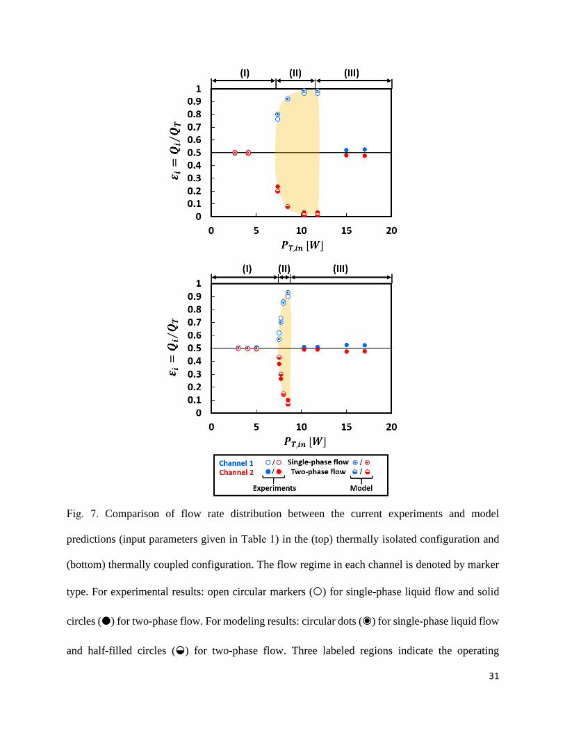
The comparison of the experimental and modeling results is presented in Fig. 7, which
shows the flow rate fraction in each channel versus the total input power for the thermally isolated
and coupled cases. In both cases, the model is able to accurately capture all of the critical features
of the experiments. The total flow rate is evenly distributed between the channels when they both
are in the single-phase liquid flow regime (I). At power levels where boiling occurs in only one of
the channels, the flow resistance in that channel increases and triggers severe flow maldistribution
via the Ledinegg instability. Excellent quantitative agreement is again observed between the
experimental measurements and model predictions. For the thermally coupled case for which all
model inputs are known a priori, the mean absolute percentage error (MAPE) in the channel 1
flow rate is 7.2% over the range of power levels where flow maldistribution occurs. Some
discrepancy is expected due to the accuracy bounds of the two-phase pressure drop and the heat
transfer coefficient correlations used in the model.
31
Fig. 7. Comparison of flow rate distribution between the current experiments and model
predictions (input parameters given in Table 1) in the (top) thermally isolated configuration and
(bottom) thermally coupled configuration. The flow regime in each channel is denoted by marker
type. For experimental results: open circular markers (○) for single-phase liquid flow and solid
circles (●) for two-phase flow. For modeling results: circular dots (◉) for single-phase liquid flow
and half-filled circles (◒) for two-phase flow. Three labeled regions indicate the operating

32
conditions where: (I) flow through both the channels is single-phase, (II) there is single-phase flow
in channel 1 and boiling in channel 2, and (III) boiling occurs in both the channels. [1 column]
This agreement between the model predictions and experiments firmly establishes the
primary conclusions of this work regarding the influence of lateral wall conduction on the flow
distribution behavior. The flow maldistribution between the two channels is mitigated in the
thermally coupled case, both in terms of the maximum severity of flow maldistribution and the
range of total input power that lead to maldistribution, as shown quantitatively in Table 2. A strong
match between the behavioral trends observed in experiments (Fig. 4a1 and Fig. 4a2) and obtained
via model predictions (Fig. 7) confirms the effect of thermal coupling, primarily, that a strong
thermal coupling leads to a more uniform flow distribution.
Table 2. A comparison of isolated versus coupled case based on the flow distribution parameters.
Thermally isolated Thermally coupled
Parameters Experiments Model Experiments Model
Maximum severity of flow maldistribution
(% of total flow rate in flow starved channel)
3.5 1.5 10 7.5
Range of input power with maldistributed
flow (W)
7.4 - 11.8 - 7.4 – 8.5 -
4. Conclusions
Existing two-phase microchannel heat sink design efforts have been typically restricted to
models that assume uniform flow. In the few approaches that have considered the flow distribution,

33
models still do not incorporate the effects of thermal coupling between the parallel channels.
Despite recent theoretical investigations that have pointed toward the importance of thermal
coupling, no experimental data on the flow distribution in boiling parallel microchannels has been
reported to verify and validate this behavior.
This study experimentally investigates, and theoretically verifies, the effect of channel-to-
channel thermal coupling on the flow maldistribution caused by the Ledinegg instability in a
system with two parallel microchannels. Deionized water is delivered at a constant total flow rate
to the channels that share common inlet and outlet plenums, and therefore have the same pressure
drop. The channels are uniformly heated and subjected to the same power level, which is increased
in steps. Two configurations are investigated, namely, thermally isolated and thermally coupled,
that have two orders of magnitude difference in the lateral thermal conductance between the
channels, with otherwise identical channel parameters. The flow rate in each channel is directly
measured simultaneously with the wall temperature and overall pressure drop across the channels,
which allows for differentiation between the thermal and hydrodynamic behaviors of these two
configurations.
Thermal coupling is observed to play a significant role in mitigating flow maldistribution
in terms of reducing the maximum severity of flow maldistribution between channels and
narrowing the range of input power over which the flow maldistribution occurs. In the most
severely maldistributed state, the starved channel receives just 3.5% of the total flow in the
thermally isolated configuration versus 10% in the thermally coupled configuration. This is
because the channel-to-channel thermal coupling allows redistribution of the heat input from the
flow-starved channel to the neighboring channel. This heat load redistribution also allows the
thermally coupled channels to attain a near-equal wall temperature irrespective of the severity of
34
flow maldistribution, with a much lower maximum wall temperature at the most severe flow
maldistribution condition. In contrast, in the thermal isolated channels, the flow-starved channel
must continue to independently dissipate its share of the heat load, which causes a large wall
temperature difference between the channels to grow with increasing power, due to the worsening
flow maldistribution. A direct comparison drawn between the experimental data and predictions
from a two-phase flow distribution model is found to have strong agreement, thereby confirming
the mitigating influence of lateral thermal coupling on flow maldistribution (resulting from the
Ledinegg instability). Lateral thermal conduction between the channels leads to a more uniform
flow distribution and wall temperature between the channels, which benefits the performance of
microchannel heat sinks where the neighboring channels are thermally coupled via a shared
substrate.
Acknowledgments
This material is based upon work supported by Ford Motor Company through the
University Research Program (URP). Special thanks to Dr. Edward Jih at Ford Research &
Advanced Engineering (R&AE) for technical discussions related to this work. The first author
would like to acknowledge the Science and Engineering Research Board (SERB) and Indo-US
Science and Technology Forum (IUSSTF) for support through a SERB Indo-US Postdoctoral
Fellowship.

35
References
[1] T.G. Karayiannis, M.M. Mahmoud, Flow boiling in microchannels: Fundamentals and
applications, Applied Thermal Engineering, 115 (2017) 1372-1397.
[2] J.B. Marcinichen, J.A. Olivier, J.R. Thome. On-chip two-phase cooling of datacenters:
Cooling system and energy recovery evaluation. Applied Thermal Engineering, 41(2012)
36-51.
[3] S. V. Garimella & T. Harirchian. Encyclopedia of Thermal Packaging: Volume 1:
Microchannel Heat Sinks for Electronics Cooling (2013).
[4] C. Park, J. Zuo, P. Rogers, J. Perez. Two-Phase flow cooling for vehicle thermal
management. SAE Technical Paper (2005) 2005-01-1769.
[5] M.J. Mackowski. Requirements for high flux cooling of future avionics systems. SAE
Technical Paper, (1991) 912104.
[6] Y. K. Prajapati & P. Bhandari. Flow boiling instabilities in microchannels and their
promising solutions–A review. Experimental Thermal and Fluid Science, 88 (2017)576-
593.
[7] A.E. Bergles, S.G. Kandlikar, On the nature of critical heat flux in microchannels, Journal
of Heat Transfer, 127(1) (2005) 101-107.
[8] J.A. Boure, A.E. Bergles, L.S. Tong, Review of two-phase flow instability, Nuclear
Engineering and Design, 25(2) (1973) 165-192.
[9] L.C. Ruspini, C.P. Marcel, A. Clausse, Two-phase flow instabilities: A review,
International Journal of Heat and Mass Transfer, 71 (2014) 521-548.
[10] L. Tadrist, Review on two-phase flow instabilities in narrow spaces, International Journal
of Heat and Fluid Flow, 28(1) (2007) 54-62.
[11] S. Kakac, B. Bon, A review of two-phase flow dynamic instabilities in tube boiling
systems, International Journal of Heat and Mass Transfer, 51(3-4) (2008) 399-433.

36
[12] E.R. Dario, L. Tadrist, J.C. Passos, Review on two-phase flow distribution in parallel
channels with macro and micro hydraulic diameters: Main results, analysis, trends, Applied
Thermal Engineering, 59(1-2) (2013) 316-335.
[13] M. Ledinegg, Instability of flow during natural and forced circulation, Die Warme, 61(8)
(1938) 891-898.
[14] S.G. Kandlikar, W.K. Kuan, D.A. Willistein, J. Borrelli, Stabilization of flow boiling in
microchannels using pressure drop elements and fabricated nucleation sites, Journal of
Heat Transfer, 128(4) (2006) 389-396.
[15] A. Koşar, C.J. Kuo and Y. Peles, Suppression of boiling flow oscillations in parallel
microchannels by inlet restrictors, Journal of Heat Transfer, 128(3) (2006) 251-260.
[16] B.A. Odom, M.J. Miner, C.A. Ortiz, J.A. Sherbeck, R.S. Prasher, P.E. Phelan,
Microchannel two-phase flow oscillation control with an adjustable inlet orifice. Journal
of Heat Transfer, 134(12), (2012) 122901.
[17] T. Zhang, J.T. Wen, A. Julius, H. Bai, Y. Peles, and M.K. Jensen, Parallel-channel flow
instabilities and active control schemes in two-phase microchannel heat exchanger
systems. In: Proceedings of the IEEE American Control Conference, June (2010) 3753-
3758.
[18] Y. Taitel, U. Minzer, D. Barnea, A control procedure for the elimination of mal flow rate
distribution in evaporating flow in parallel pipes. Solar Energy, 82(4) (2008) 329-335.
[19] C.J. Kuo, Y.Peles, Pressure effects on flow boiling instabilities in parallel
microchannels, International Journal of Heat and Mass Transfer, 52(1-2) (2009) 271-280.
[20] K. Akagawa, M. Kono, T. Sakaguchi, M. Nishimura, Study on distribution of flow rates
and flow stabilities in parallel long evaporators, Bulletin of Japan Society of Mechanical
Engineers, 14(74) (1971) 837-848.
[21] U. Minzer, D. Barnea, Y. Taitel, Evaporation in parallel pipes - splitting characteristics,
International Journal of Multiphase Flow, 30(7-8) (2004) 763-777.

37
[22] U. Minzer, D. Barnea, Y. Taitel, Flow rate distribution in evaporating parallel pipes -
modeling and experimental, Chemical Engineering Science, 61(22) (2006) 7249-7259.
[23] T.A. Kingston, J.A. Weibel, S.V. Garimella, Ledinegg instability-induced temperature
excursion between thermally isolated, heated parallel microchannels, International
Journal of Heat and Mass Transfer, 132 (2019) 550-556.
[24] A. Miglani, J.A. Weibel, S.V. Garimella, Measurement of flow maldistribution induced by
the Ledinegg instability during boiling in thermally isolated parallel
microchannels, International Journal of Multiphase Flow, in review
[25] R.D. Flynn, D.W. Fogg, J.-M. Koo, C.-H. Cheng, K.E. Goodson, Boiling flow interaction
between two parallel microchannels, In: Proceedings of ASME International Mechanical
Engineering Congress and Exposition, Nov. 5-10, Chicago, Illinois, USA, 47853 (2006)
317-322.
[26] S. N. Ritchey, J. A. Weibel, S. V. Garimella, Local measurement of flow boiling heat
transfer in an array of non-uniformly heated microchannels. International Journal of Heat
and Mass Transfer, 71 (2014) 206-216.
[27] E. S. Cho, J. W. Choi, J. S. Yoon, M. S. Kim, Experimental study on microchannel heat
sinks considering mass flow distribution with non-uniform heat flux
conditions. International Journal of Heat and Mass Transfer, 53(9-10) (2010) 2159-2168.
[28] T. Zhang, J. T. Wen, A. Julius, Y. Peles, M. K. Jensen, Stability analysis and
maldistribution control of two-phase flow in parallel evaporating channels. International
Journal of Heat and Mass Transfer, 54(25-26) (2011) 5298-5305.
[29] R. Flynn, C.-H. Cheng, K. Goodson, Decoupled thermal and fluidic effects on hotspot
cooling in a boiling flow microchannel heat sink, In: Proceedings of ASME International
Technical Conference and Exhibition on Packaging and Integration of Electronic and
Photonic Microsystem, July 8 – 7, Vancouver, British Columbia, Canada, 42770 (2007)
179-184.
38
[30] T. Van Oevelen, J.A. Weibel, S.V. Garimella, The effect of lateral thermal coupling
between parallel microchannels on two-phase flow distribution, International Journal of
Heat and Mass Transfer, 124 (2018) 769-781.
[31] T. Van Oevelen, J.A. Weibel, S.V. Garimella, Predicting two-phase flow distribution and
stability in systems with many parallel heated channels, International Journal of Heat and
Mass Transfer, 107 (2017) 557-571.
[32] T. Zhang, T. Tong, J.Y. Chang, Y. Peles, R. Prasher, M.K. Jensen, J.T. Wen, P. Phelan,
Ledinegg instability in microchannels, International Journal of Heat and Mass
Transfer, 52(25-26) (2009) 5661-5674.