Embed Size (px)
Citation preview
AN EXPERIMENTAL STUDY ON FRICTION DRILLING OF ST12 STEEL
Mehmet Tuncay Kaya1, Alaattin Aktas2, Bertan Beylergil3 and Hamza K. Akyildiz11Department of Mechanical Engineering, Faculty of Engineering and Architecture,
Bozok University, 66000 Yozgat, Turkey2Department of Mechanical Engineering, Faculty of Engineering, Istanbul University,
34320 Avcilar, Istanbul, Turkey3Department of Mechanical Engineering, Faculty of Engineering, Izmir Institute of Technology,
35347 Urla, Izmir, TurkeyE-mail: [email protected]; [email protected]
Received May 2013, Accepted May 2014No. 13-CSME-134, E.I.C. Accession 3592
ABSTRACTThe aim of this study is to investigate the effects of drilling parameters such as friction angle, frictioncontact area ratio (FCAR), feed rate and spindle speed on workpiece surface temperature, thrust force andtorque in friction drilling of ST12 material. The tool material is tungsten carbide coated with TiN treatment.Experimental results reveal that the thrust force and torque increases gradually with increasing friction angle,feed rate and FCAR. On the other hand, the thrust force and torque decreases with increasing drilling speed.It is found that drilling speed has an important effect on the workpiece surface temperature. As the drillingspeed increases, the workpiece surface temperature increases. Increasing or decreasing the friction angleand FCAR has no significant effect on the workpiece surface temperature.
Keywords: chipless hole making; ST12; friction angle; FCAR; feed rate; spindle speed.
UNE ÉTUDE EXPÉRIMENTALE SUR LE PERÇAGE PAR FRICTION D’UN ACIER ST12
RÉSUMÉLe but de l’étude est d’investiguer les effets des paramètres de friction, tels que l’angle de friction, le rapportde l’aire de contact de la friction (friction contact area ratio (FCAR) ; la vitesse d’avancement et la vitesse dela broche sur la température de la surface de la pièce, et la poussée force et torsion dans le perçage par frictiond’un acier ST12. La composition de l’outil est faite de carbure et de tungstène recouvert d’étain. Les résultatsdes expériences révèlent que la poussée force et torsion augmente graduellement avec l’accroissement del’angle de friction, la vitesse d’avancement et le FCAR. D’autre part, la poussée force et torsion diminueavec l’accroissement de la vitesse du perçage. On constate que la vitesse du perçage a un effet importantsur la température de la surface de la pièce. Au fur et à mesure que la vitesse de perçage augmente, latempérature de la surface de la pièce s’accroît. L’augmentation ou la diminution de l’angle de friction et leFCAR n’a aucun effet significatif sur la température de la surface de la pièce.
Mots-clés : perçage sans copeaux; ST12; angle de friction; FCAR; vitesse d’avancement; vitesse de labroche.
Transactions of the Canadian Society for Mechanical Engineering, Vol. 38, No. 3, 2014 319
1. INTRODUCTION
Drilling plays a very important role in machining since more than 40% of material removal processes areassociated with this type of operation. Traditionally, a drilling tool is generally made of high speed steel(HSS). It generates high temperature during drilling process. Therefore, the drilling tool becomes dull andleads to a shortened service life. Moreover, the workpiece materials have been hardened during drillingprocess which makes the post-process troublesome. Also, the chips adhered to the exit of a drilled holedamages the surface quality and deteriorates the machining precision. Friction drilling, also known as“thermal drilling”, “flow drilling”, “form drilling”, or “friction stir drilling”, is the best solution to theaforementioned problems [1–3].
Friction drilling utilizes the heat generated from the friction between a rotating conical tool and the work-piece. The tool is often made of tungsten carbide and rotates at high speed, which produces friction heat.The process forms a bushing in situ and is clean and chipless. This chipless machining process has theadvantage of reducing the time required for drilling and incurring less tool wear, thus lengthening the ser-vice life of the drill. Also, unlike traditional drilling that uses cutting fluid to reduce the friction and heatgeneration, friction drilling is a dry process [4, 5].
Research on the subject of friction drilling is rare and the following review summarizes some of thesestudies; Ku et al. [5] developed a new type of thermal friction drill made of sintered carbide and theyinvestigated the effects of friction angle, friction contact area ratio, feed rate, and spindle speed on thetwo quality characteristics, surface roughness and bushing length. They reported the optimal machiningparameters for surface roughness and bushing length. Lee et al. [6] applied friction drilling method toIN- 713LC cast and examined different quality characteristics such as hole roundness, surface roughnessand hardness of hole wall. France [7–9] studied the strength characteristics of friction drilled holes inmetal tubes. Chow et al. [10] carried out experiments using AISI304 stainless steel as a workpiece ma-terial and showed that the drilled surroundings area obtained fine grain size and compact structure with ahigher micro hardness than that of the area away from the drilled area. Miller et al. [11] applied frictiondrilling to machine different materials viz. low-carbon steel, aluminum and magnesium alloys and inves-tigated the relationship between axial thrust force and torque under different spindle speeds and feed ratesexperimentally. Lee et al. [12] utilized friction drilling to make holes using tungsten carbide drills withand without coating in AISI 304 stainless steel. The authors showed that coated drills suffered less toolwear than uncoated drills at the same spindle speed and for the same number of holes drilled. Folea et al.[13] studied friction drilling of two types of maraging steel workpieces (flat and cylindrical). The authorsshowed that temperature was the most significant factor in friction drilling process. They also reportedthat superior quality of the drilled holes could be obtained with higher speeds both on flat and cylindricalworkpieces.
However, there is no research related specifically to ST12 steel as a workpiece material for friction drillingprocess. ST12 steel is being widely used such as automobile manufacturing, electrical products, rollingstock, aerospace, precision instruments and is a good candidate for friction drilling. Therefore, the novelprocess of the thermal friction drilling needs a further and comprehensive study to understand the effectsof drilling parameters on ST12 steel. The main purpose of this paper is to investigate the effects of somemachining parameters of the thermal friction drilling process on ST12 steel. The machining parameters areconsidered as follows: friction angle (300, 450 and 600), friction contact area ratio (FCAR, 50 and 100%),feed rate (from 100 to 500 mm/min with an increment of 50 mm/min) and spindle speed (3000, 4500 and6000 rpm). The effects of these parameters on workpiece surface temperature, thrust force and torqueare examined. Experimental results show that the thrust force and torque increases gradually as frictionangle, feed rate and FCAR increase. On the other hand, the thrust force and torque decreases as spindlespeed increases. The results reveal that spindle speed has an important effect on the workpiece surface
Transactions of the Canadian Society for Mechanical Engineering, Vol. 38, No. 3, 2014320
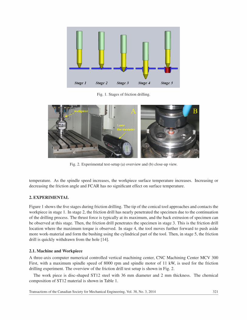
Fig. 1. Stages of friction drilling.
Fig. 2. Experimental test-setup (a) overview and (b) close-up view.
temperature. As the spindle speed increases, the workpiece surface temperature increases. Increasing ordecreasing the friction angle and FCAR has no significant effect on surface temperature.
2. EXPERIMENTAL
Figure 1 shows the five stages during friction drilling. The tip of the conical tool approaches and contacts theworkpiece in stage 1. In stage 2, the friction drill has nearly penetrated the specimen due to the continuationof the drilling process. The thrust force is typically at its maximum, and the back extrusion of specimen canbe observed at this stage. Then, the friction drill penetrates the specimen in stage 3. This is the friction drilllocation where the maximum torque is observed. In stage 4, the tool moves further forward to push asidemore work-material and form the bushing using the cylindrical part of the tool. Then, in stage 5, the frictiondrill is quickly withdrawn from the hole [14].
2.1. Machine and WorkpieceA three-axis computer numerical controlled vertical machining center, CNC Machining Center MCV 300First, with a maximum spindle speed of 8000 rpm and spindle motor of 11 kW, is used for the frictiondrilling experiment. The overview of the friction drill test setup is shown in Fig. 2.
The work piece is disc-shaped ST12 steel with 36 mm diameter and 2 mm thickness. The chemicalcomposition of ST12 material is shown in Table 1.
Transactions of the Canadian Society for Mechanical Engineering, Vol. 38, No. 3, 2014 321
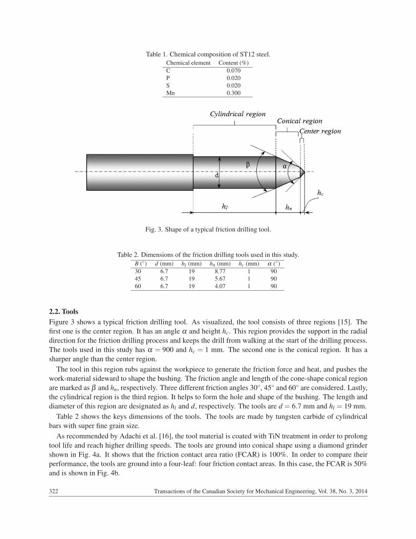
Table 1. Chemical composition of ST12 steel.Chemical element Content (%)C 0.070P 0.020S 0.020Mn 0.300
Fig. 3. Shape of a typical friction drilling tool.
Table 2. Dimensions of the friction drilling tools used in this study.B (◦) d (mm) hl (mm) hn (mm) hc (mm) α (◦)30 6.7 19 8.77 1 9045 6.7 19 5.67 1 9060 6.7 19 4.07 1 90
2.2. ToolsFigure 3 shows a typical friction drilling tool. As visualized, the tool consists of three regions [15]. Thefirst one is the center region. It has an angle α and height hc. This region provides the support in the radialdirection for the friction drilling process and keeps the drill from walking at the start of the drilling process.The tools used in this study has α = 900 and hc = 1 mm. The second one is the conical region. It has asharper angle than the center region.
The tool in this region rubs against the workpiece to generate the friction force and heat, and pushes thework-material sideward to shape the bushing. The friction angle and length of the cone-shape conical regionare marked as β and hn, respectively. Three different friction angles 30◦, 45◦ and 60◦ are considered. Lastly,the cylindrical region is the third region. It helps to form the hole and shape of the bushing. The length anddiameter of this region are designated as hl and d, respectively. The tools are d = 6.7 mm and hl = 19 mm.
Table 2 shows the keys dimensions of the tools. The tools are made by tungsten carbide of cylindricalbars with super fine grain size.
As recommended by Adachi et al. [16], the tool material is coated with TiN treatment in order to prolongtool life and reach higher drilling speeds. The tools are ground into conical shape using a diamond grindershown in Fig. 4a. It shows that the friction contact area ratio (FCAR) is 100%. In order to compare theirperformance, the tools are ground into a four-leaf: four friction contact areas. In this case, the FCAR is 50%and is shown in Fig. 4b.
Transactions of the Canadian Society for Mechanical Engineering, Vol. 38, No. 3, 2014322
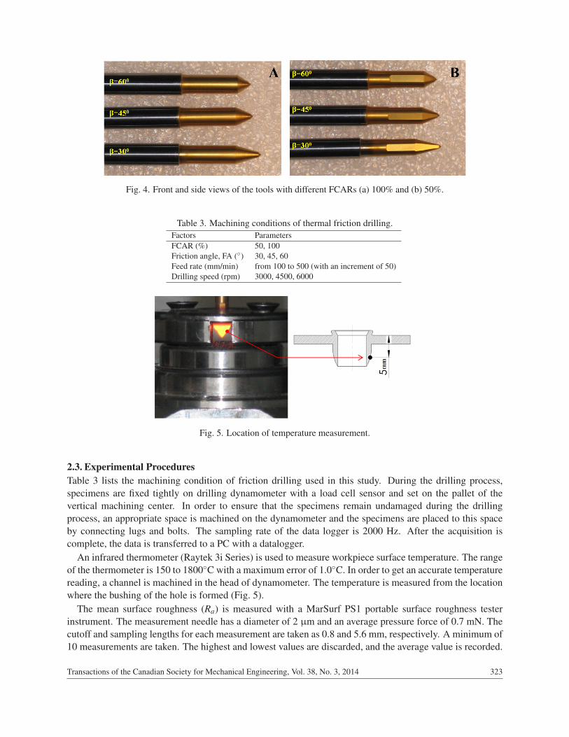
Fig. 4. Front and side views of the tools with different FCARs (a) 100% and (b) 50%.
Table 3. Machining conditions of thermal friction drilling.Factors ParametersFCAR (%) 50, 100Friction angle, FA (◦) 30, 45, 60Feed rate (mm/min) from 100 to 500 (with an increment of 50)Drilling speed (rpm) 3000, 4500, 6000
Fig. 5. Location of temperature measurement.
2.3. Experimental ProceduresTable 3 lists the machining condition of friction drilling used in this study. During the drilling process,specimens are fixed tightly on drilling dynamometer with a load cell sensor and set on the pallet of thevertical machining center. In order to ensure that the specimens remain undamaged during the drillingprocess, an appropriate space is machined on the dynamometer and the specimens are placed to this spaceby connecting lugs and bolts. The sampling rate of the data logger is 2000 Hz. After the acquisition iscomplete, the data is transferred to a PC with a datalogger.
An infrared thermometer (Raytek 3i Series) is used to measure workpiece surface temperature. The rangeof the thermometer is 150 to 1800◦C with a maximum error of 1.0◦C. In order to get an accurate temperaturereading, a channel is machined in the head of dynamometer. The temperature is measured from the locationwhere the bushing of the hole is formed (Fig. 5).
The mean surface roughness (Ra) is measured with a MarSurf PS1 portable surface roughness testerinstrument. The measurement needle has a diameter of 2 µm and an average pressure force of 0.7 mN. Thecutoff and sampling lengths for each measurement are taken as 0.8 and 5.6 mm, respectively. A minimum of10 measurements are taken. The highest and lowest values are discarded, and the average value is recorded.
Transactions of the Canadian Society for Mechanical Engineering, Vol. 38, No. 3, 2014 323
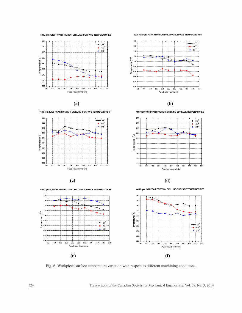
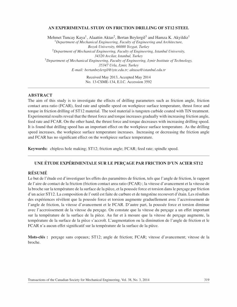
Fig. 6. Workpiece surface temperature variation with respect to different machining conditions.
Transactions of the Canadian Society for Mechanical Engineering, Vol. 38, No. 3, 2014324
3. RESULTS AND DISCUSSION
3.1. Workpiece TemperatureFigure 6 shows the variation of workpiece surface temperature according to the examined parameters. Asseen in Fig. 6(a), the minimum surface temperature of 6240C is obtained when the drilling is performedby a drilling tool with 450 friction angle and 100% FCAR under the operation condition of spindle speedof 3000 rpm, and feed rate of 100 mm/min. The results reveal that generally the temperature measuredin drilling operations performed by a drilling tool with 450 friction angle is lower than drilling tools withangles of 30◦ and 60◦. As seen in Fig. 6(f), the maximum surface temperature of 775◦C is obtained whendrilling is performed by a drilling tool with 30◦ friction angle and 50% FCAR under the operating conditionof spindle speed of 6000 rpm, and feed rate of 100 mm/min. The reason is that the hn length of the drillingtool is longer compared with hn length of drilling tolls with friction angles of 45 and 60◦. The hn lengthbeing longer, causes the piece to be drilled quicker during the drilling operation and causes the pressurebetween drilling tool and workpiece to occur in a narrower area. It is observed that surface temperatureincreases with the increase of spindle speed and vice versa. The results are similar to those reported byMiller et al. [1].
It is also observed that the friction contact area ratio does not have a significant effect on surface tem-perature while spindle speed and feed rate are constant. For example, in Fig. 6(c), a surface temperature of708◦C is obtained when drilling is performed by a drilling tool with 45◦ friction angle under the operatingconditions of spindle speed of 4500 rpm, feed rate of 100 mm/min. It can be seen that the temperature is710◦C under the same conditions (Fig. 6d).
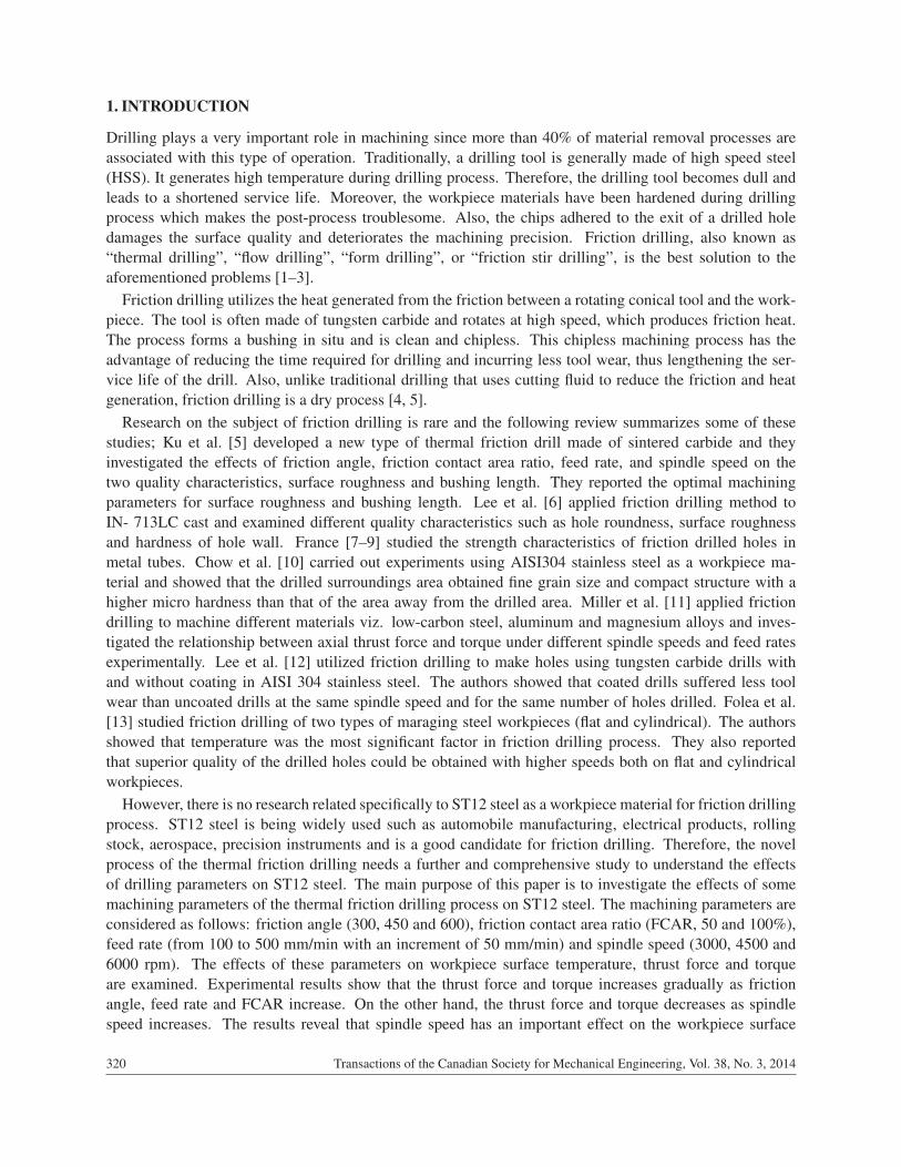
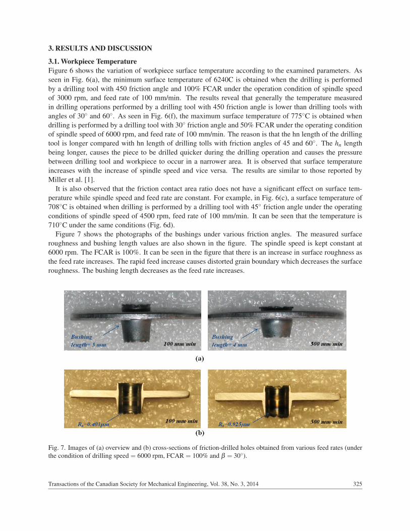
Figure 7 shows the photographs of the bushings under various friction angles. The measured surfaceroughness and bushing length values are also shown in the figure. The spindle speed is kept constant at6000 rpm. The FCAR is 100%. It can be seen in the figure that there is an increase in surface roughness asthe feed rate increases. The rapid feed increase causes distorted grain boundary which decreases the surfaceroughness. The bushing length decreases as the feed rate increases.
Fig. 7. Images of (a) overview and (b) cross-sections of friction-drilled holes obtained from various feed rates (underthe condition of drilling speed = 6000 rpm, FCAR = 100% and β = 30◦).
Transactions of the Canadian Society for Mechanical Engineering, Vol. 38, No. 3, 2014 325
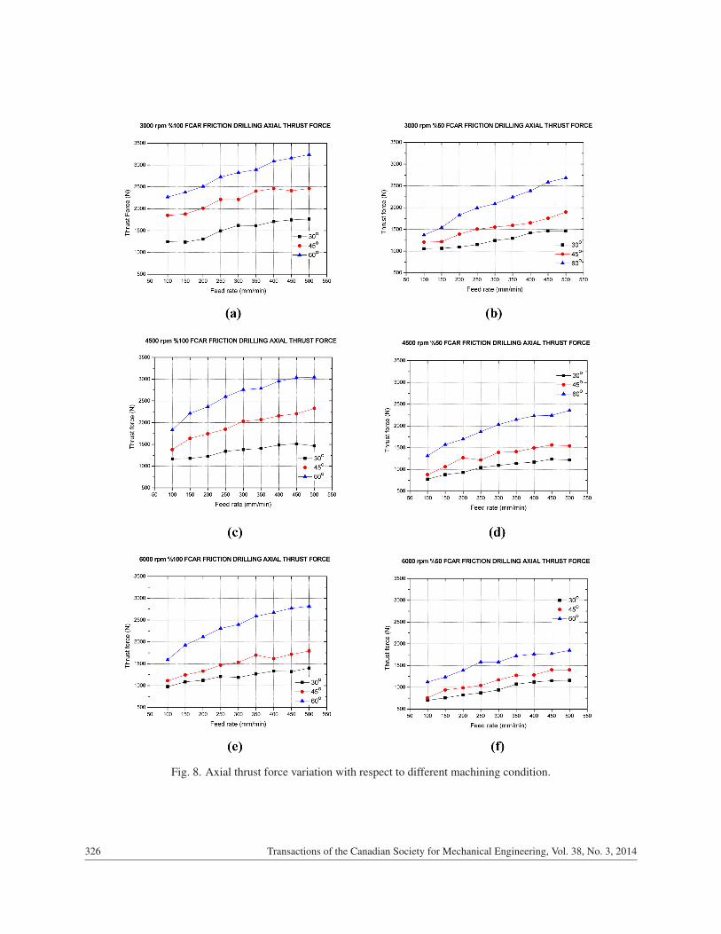
Fig. 8. Axial thrust force variation with respect to different machining condition.
Transactions of the Canadian Society for Mechanical Engineering, Vol. 38, No. 3, 2014326
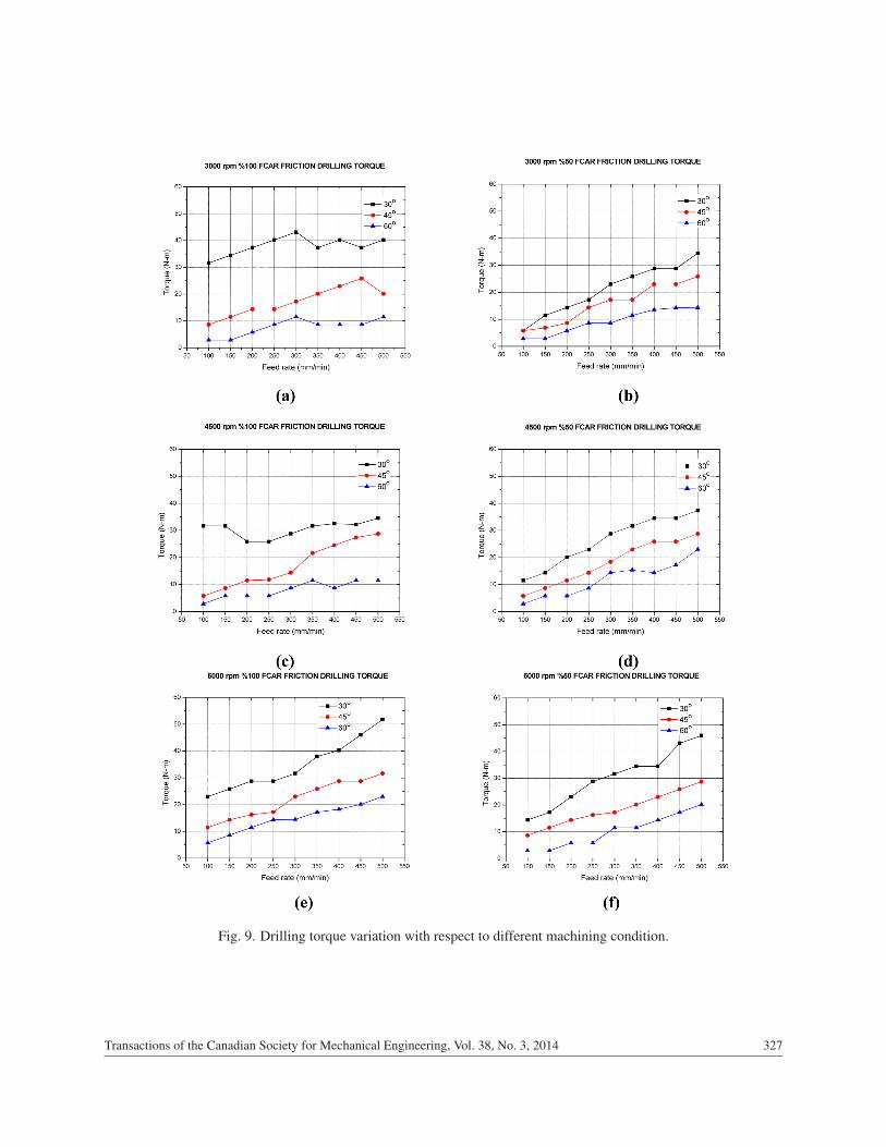
Fig. 9. Drilling torque variation with respect to different machining condition.
Transactions of the Canadian Society for Mechanical Engineering, Vol. 38, No. 3, 2014 327
3.2. Thrust Force and TorqueFigure 8 shows the variation in axial thrust force according to the investigated parameters. It is foundthat thrust force values increase due to the increasing feed rate and decreasing spindle speed. The reasonis considered to be the increase in friction surface between workpiece and drilling tool. Besides it is alsoobserved that thrust force value increases due to the increase in friction angle. The reason is that penetrationof drilling tool to the workpiece becomes difficult due to increasing friction angle. High thrust force is anunwelcomed situation because it shortens life of the tool. The results are similar to those reported by Krishaet al. [4]. As seen in Fig. 8(a), the thrust forces for friction angles 30, 45 and 60◦ are 1245, 1849 and 2268 N,respectively.
It is also seen that friction contact area ratio has a significant effect on thrust force in constant spindlespeed and feed rate. For example as observed in Figs. 8(b) and 8(c) while the FCAR decreases from 100to 50% with spindle speed of 4500 rpm, feed rate of 100 mm/min and friction angle of 45◦, the thrustforce decreases from 1380 to 881 N. The reason is the increase of pressure between drilling tool and workpiece due to friction contact area ratio decrease. Accordingly this causes easy deformation in workpiece.Maximum thrust force is determined as 3238 N with spindle speed of 3000 rpm, feed rate of 500 mm/minand friction angle of 60◦. Minimum thrust force is determined as 699 N with spindle speed of 6000 rpm,feed rate of 100 mm/min and friction angle of 30◦.
Figure 9 shows the drilling torque values according to examined parameters. Similar to thrust force, it isobserved that drilling torque values increase due to the increasing feed rate. Minimum torque is obtainedwith a drilling tool having 60◦ friction angles while the spindle speed and feed rate are 3000 rpm and 100mm/min, respectively (Fig. 9a). As seen in Fig. 9(e), maximum torque is obtained with a drilling toolhaving 30◦ friction angles while the maximum spindle speed and feed rate are 6000 rpm and 500 mm/min,respectively. Besides it is determined that drilling torque decreases due to the decreasing friction contactsurface. The reason is the decrease of friction area.
4. CONCLUSIONS
This study investigates the thermal friction drilling effects on surface temperature, thrust force and torquefor ST12 steel. Experimental data support the following conclusions:
• Thrust force and torque increases gradually with increasing friction angle, feed rate and FCAR.
• Thrust force and torque decreases with increasing spindle speed.
• As the spindle speed increases, the workpiece surface temperature increases.
• Increasing or decreasing the friction angle and FCAR has no significant effect on workpiece surfacetemperature.
• There is an increase in surface roughness as the feed rate increases.
• The bushing length decreases as the feed rate increases.
ACKNOWLEDGEMENT
One of the authors (A.A.) wishes to thank the Turkish Academy of Sciences (TUBA) for its support.
REFERENCES
1. Miller, S.F., Tao, J. and Shih, A.J., “Friction drilling of cast metals”, International Journal of Machine Tools &Manufacture, Vol. 46, Nos. 12–13, pp. 1526–1535, 2006.
Transactions of the Canadian Society for Mechanical Engineering, Vol. 38, No. 3, 2014328
2. van Geffen, J.A., “Piercing tools”, US Patent 3939683, 1976.3. Su, Y.L., Liu, T.H., Su, C.T., Yao, S.H., Kao, W.H. and Cheng, K.W., “Wear of CrC-coated carbide tools in dry
machining”, Journal of Materials Processing Technology, Vol. 171, No. 1, pp. 108–117, 2006.4. Krishna, P.V., Kishore, K. and Satyanarayana, V.V., “Some investigations in friction drilling AA6351 using high
speed steel tools”, Journal of Engineering & Applied Sciences, Vol. 5, No. 3, pp. 81–88, 2010.5. Ku, W.L., Hung, C.L., Lee, S.M. and Chow, H.M., “Optimization in thermal friction drilling for SUS 304
stainless steel”, The International Journal of Advanced Manufacturing Technology, Vol. 53, Nos. 9–12, pp.935–944, 2011.
6. Lee, S.M., Chow, H.M. and Yan, B.H., “Friction drilling of IN-713LC cast super alloy”, Materials and Manu-facturing Processes, Vol. 22, Nos. 7–8, pp. 893–897, 2007.
7. France, J.E., Davidson, J.B. and Kirby, P.A., “Strength and rotational stiffness of simple connections to tubularcolumns using flowdrill connectors”, �Journal of Constructional Steel Research, Vol. 50, No. 1, pp. 15–34, 1999.
8. France, J.E., Davidson, J.B. and Kirby, P.A., “Moment-capacity and rotational stiffness of endplate connectionsto concrete-filled tubular columns with flowdrill connectors”, Journal of Constructional Steel Research, Vol. 50,No. 1, pp. 35–48, 1999.
9. France, J.E., Davidson, J.B. and Kirby, P.A., “Strength and rotational response of moment connections to tubularcolumns using flowdrill connectors”, Journal of Constructional Steel Research, Vol. 50, No. 1, pp. 1–14, 1999.
10. Chow, H-M., Lee, S-M. and Yang, L-D., “Machining characteristic study of friction drilling on AISI 304 stainlesssteel”, Journal of Materials Processing Technology, Vol. 207, Nos. 1–3, pp. 180–186, 2008.
11. Miller, S.F., Blau, P.J. and Shih, A.J., “Tool wear in friction drilling”, International Journal of Machine Toolsand Manufacture, Vol. 47, No. 10, pp. 1636–1645, 2007.
12. Lee, S.M., Chow, H.M., Huang, F.Y. and Yan, B.H., “Friction drilling of austenitic stainless steel by uncoatedand PVD AlCrN- and TiAlN-coated tungsten carbide tools”, International Journal of Machine Tools and Man-ufacture, Vol. 49, No. 1, pp. 81–88, 2009.
13. Folea, M., Schlegel, D., Gete, E., Langlade, C. and Roman, A., “Preliminary tests on flow drilling of maragingsteels”, Academic Journal of Manufacturing Engineering, Vol. 10, No. 4, pp. 42–47, 2012.
14. Miller, S.F., Li, R., Wang, H. and Shih, A.J., “Experimental and numerical analysis of the friction drillingprocess”, Journal of Manufacturing Science and Engineering, Vol. 128, No. 3, pp. 802–810, 2006.
15. Miller, S.F., Experimental Analysis and Numerical Modeling of the Friction Drilling, PhD Dissertation, Univer-sity of Michigan, 2006.
16. Adachi, K., Arai, N., Okita, K., Ogawa, K. and Niba, R., “A study on drilling of SUS304 by TiN-coated drills”,International Journal of the Japan Society for Precision Engineering, Vol. 24, No. 3, pp. 200–205, 1990.
Transactions of the Canadian Society for Mechanical Engineering, Vol. 38, No. 3, 2014 329