Embed Size (px)
Citation preview
An expert system for distribution substation fault diagnosis and backup protection J Trecat Department of Electrical Engineering, Faculte Polytechnique, 7000 Mons, Belgium
Wang Jianping Department of Electrical Engineering, Southwest Jiaotong University, Emei, Sichuan, People's Republic of China
Using Prolog, this paper presents an expert system for fault section diagnosis in a substation primary system, backup protection and fauh finding in protective systems. The expert system is intended for use in distribution substations.
Keywords: expert system, fault diagnosis, distribution subsystems
I. Introduction In distribution substations, conventional fault diagnosis and fault finding functions are performed by operators. Upon receiving the information from circuit breakers and relays, the operator will read the sequence of signals to find the faulty components in the primary system and/or faulty devices in the relays or circuit breakers. This method is not reliable because it relies on the operator's experience. In order to increase the reliability in this field and relieve the operator's work load, an expert system method is introduced in this paper.
Expert systems for fault diagnosis have been reported. Sakaguchi et al. ~ presented a rule-based expert system to diagnose power system faults using the information from protective devices. They proposed a diagnosis method using logic circuit to simulate the performance of protective systems. When faulty information is given to the logical circuit, faulty components are indicated. Fukui and Kawakami 2 have carried out a similar task using Prolog. Since these diagnostic expert systems were intended for use in the dispatching centres, they are not suitable for distribution substations. Moreover, the
Received: September 1988; revised 9 January 1989
backup protection functions have not been considered in these expert systems.
As is well known, an expert system is a set of computer programs which use current information, a knowledge base and an inference engine to solve special problems in a manner similar to that of a human expert.
The knowledge base includes a group of production rules and facts. The inference engine consists of a search space tree which determines the heuristic search structure in the expert system.
Before building an expert system, it is necessary to select a suitable software tool. In this paper, Prolog has been selected as a language tool for the expert system. It should be emphasized that the two outstanding features of Prolog are pattern-matching and backtracking 3. Since Prolog has many advantages in representing knowledge and is available for PCs as Turbo Prolog, it has been used to build our expert system.
II. Substation configurat ion and expert system functions
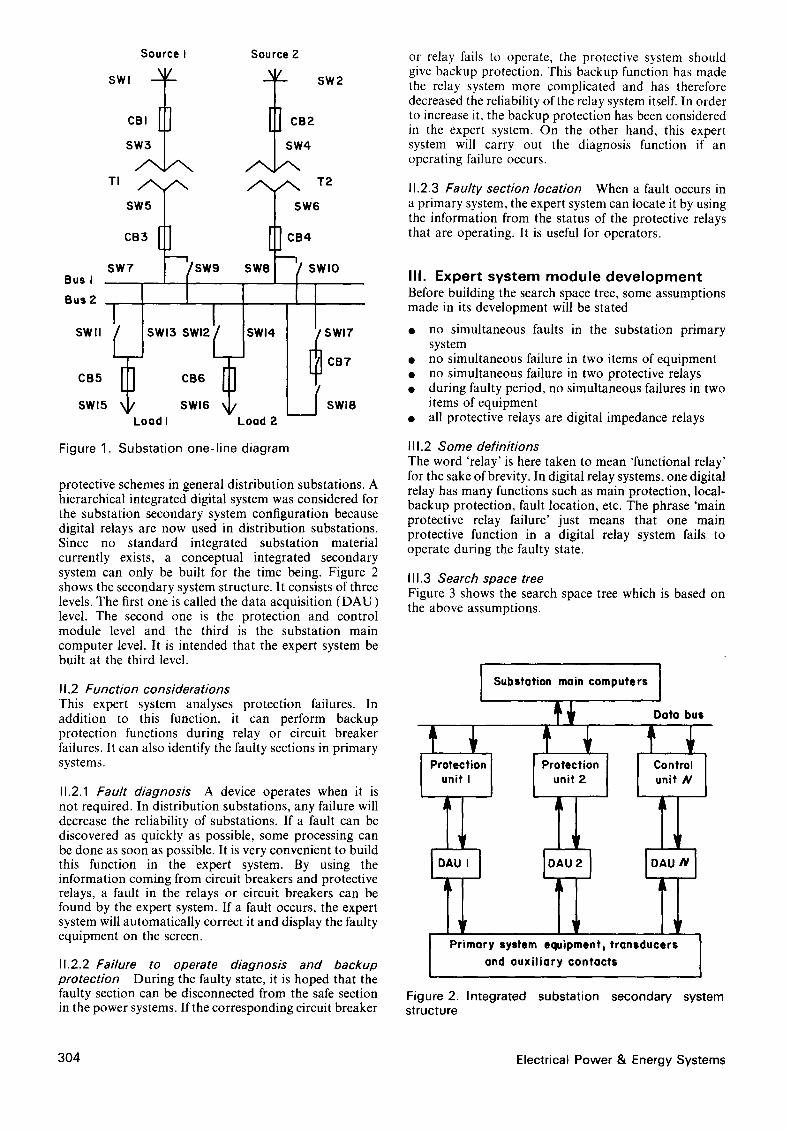
I1.1 Substation configuration Before discussing expert system functions, the substation configurations will be given. Based on the concepts of simplicity and generality, a 2-busbar substation con- figuration was selected as the primary system structure. The configuration presented here is intended to be a simple example for the purpose of AI applications but it can be easily generalized. The structure of this primary system can be used as a general structure in AC railway substations or in distribution substations.
Figure 1 shows the primary system configuration. It includes a series of typical operation and different
Vol 13 No 6 December 1991 0142-0615/91/060303-05 © 1991 Butterworth-Heinemann Ltd 303
Bus I
Bus ?-
Source I swl \ /
CBI ] SW3
SW5
CB$
SW7 -'~(SW9
SWll ( SWI3 SWl2
CB5
SWl5
CB6
Source Z
/ sw2
CB2
SW4
A / ~ T2 SW6
CB4 m
SWe SWlO
i SWl4 I SWl7
r3 CB7
SWl6 L/ Load I Load 2
SWI8
Figure 1. Substation one-line diagram
protective schemes in general distribution substations. A hierarchical integrated digital system was considered for the substation secondary system configuration because digital relays are now used in distribution substations. Since no standard integrated substation material currently exists, a conceptual integrated secondary system can only be built for the time being. Figure 2 shows the secondary system structure. It consists of three levels. The first one is called the data acquisition (DAU) level. The second one is the protection and control module level and the third is the substation main computer level. It is intended that the expert system be built at the third level.
11.2 Function considerations This expert system analyses protection failures. In addition to this function, it can perform backup protection functions during relay or circuit breaker failures. It can also identify the faulty sections in primary systems.
11.2.1 Fault diagnosis A device operates when it is not required. In distribution substations, any failure will decrease the reliability of substations. If a fault can be discovered as quickly as possible, some processing can be done as soon as possible. It is very convenient to build this function in the expert system. By using the information coming from circuit breakers and protective relays, a fault in the relays or circuit breakers can be found by the expert system. If a fault occurs, the expert system will automatically correct it and display the faulty equipment on the screen.
11.2.2 Failure to operate diagnosis and backup protection During the faulty state, it is hoped that the faulty section can be disconnected from the safe section in the power systems. If the corresponding circuit breaker
or relay fails to operate, the protective system should give backup protection. This backup function has made the relay system more complicated and has therefore decreased the reliability of the relay system itself. In order to increase it, the backup protection has been considered in the expert system. On the other hand, this expert system will carry out the diagnosis function if an operating failure occurs.
11.2.3 Faulty section location When a fault occurs in a primary system, the expert system can locate it by using the information from the status of the protective relays that are operating. It is useful for operators.
I I I . E x p e r t s y s t e m m o d u l e d e v e l o p m e n t Before building the search space tree, some assumptions made in its development will be stated
• no simultaneous faults in the substation primary system
• no simultaneous failure in two items of equipment • no simultaneous failure in two protective relays • during faulty period, no simultaneous failures in two
items of equipment • all protective relays are digital impedance relays
111.2 Some definitions The word 'relay' is here taken to mean 'functional relay' for the sake of brevity. In digital relay systems, one digital relay has many functions such as main protection, local- backup protection, fault location, etc. The phrase 'main protective relay failure' just means that one main protective function in a digital relay system fails to operate during the faulty state.
111.3 Search space tree Figure 3 shows the search space tree which is based on the above assumptions.
Substation main computers
[.ro,--.o°l [.ro,.o.on] ["n"o'l
~ Pri m a raYn; Y : t : ~ ~ ; : s r a n s clu ¢ e r s ]
Figure 2. Integrated substation secondary system structure
304 Electrical Power & Energy Systems
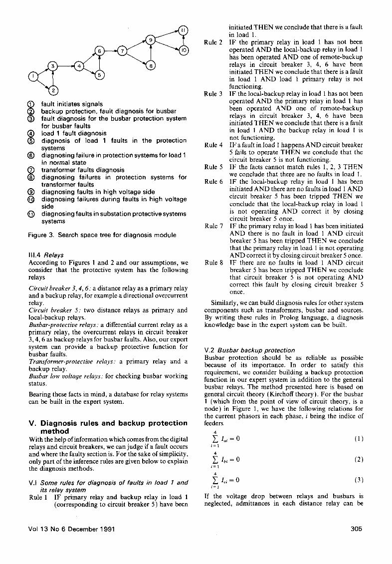
(~ fault initiates signals backup protection, fault diagnosis for busbar fault diagnosis for the busbar protection system for busbar faults load 1 fault diagnosis diagnosis of load 1 faults in the protection systems
(~) diagnosing failure in protection systems for load 1 in normal state
C) transformer faults diagnosis (~) diagnosing failures in protection systems for
transformer faults (~) diagnosing faults in high voltage side (~ diagnosing failures during faults in high voltage
side (~) diagnosing faults in substation protective systems
systems
Figure 3. Search space tree for diagnosis module
111.4 Relays According to Figures 1 and 2 and our assumptions, we consider that the protective system has the following relays
Circuit breaker 3, 4, 6: a distance relay as a primary relay and a backup relay, for example a directional overcurrent relay. Circuit breaker 5: two distance relays as primary and local-backup relays. Busbar-protective relays: a differential current relay as a primary relay, the overcurrent relays in circuit breaker 3, 4, 6 as backup relays for busbar faults. Also, our expert system can provide a backup protective function for busbar faults. Transformer-protective relays: a primary relay and a backup relay. Busbar low voltage relays: for checking busbar working status.
Bearing these facts in mind, a database for relay systems can be built in the expert system.
V. Diagnosis rules and backup protect ion method
With the help of information which comes from the digital relays and circuit breakers, we can judge if a fault occurs and where the faulty section is. For the sake of simplicity, only part of the inference rules are given below to explain the diagnosis methods.
V.I Some rules for diagnosis of faults in load 1 and its relay system
Rule 1 IF primary relay and backup relay in load 1 (corresponding to circuit breaker 5) have been
initiated THEN we conclude that there is a fault in load 1.
Rule 2 IF the primary relay in load 1 has not been operated AND the local-backup relay in load 1 has been operated AND one of remote-backup relays in circuit breaker 3, 4, 6 have been initiated THEN we conclude that there is a fault in load 1 AND load 1 primary relay is not functioning.
Rule 3 IF the local-backup relay in load 1 has not been operated AND the primary relay in load 1 has been operated AND one of remote-backup relays in circuit breaker 3, 4, 6 have been initiated THEN we conclude that there is a fault in load 1 AND the backup relay in load 1 is not functioning.
Rule 4 IF a fault in load 1 happens AND circuit breaker 5 fails to operate THEN we conclude that the circuit breaker 5 is not functioning.
Rule 5 IF the facts cannot match rules 1, 2, 3 THEN we conclude that there are no faults in load 1.
Rule 6 IF the local-backup relay in load 1 has been initiated AND there are no faults in load I AND circuit breaker 5 has been tripped THEN we conclude that the local-backup relay in load 1 is not operating AND correct it by closing circuit breaker 5 once.
Rule 7 IF the primary relay in load 1 has been initiated AND there is no fault in load 1 AND circuit breaker 5 has been tripped THEN we conclude that the primary relay in load 1 is not operating AND correct it by closing circuit breaker 5 once.
Rule 8 IF there are no faults in load 1 AND circuit breaker 5 has been tripped THEN we conclude that circuit breaker 5 is not operating AND correct this fault by closing circuit breaker 5 once.
Similarly, we can build diagnosis rules for other system components such as transformers, busbar and sources. By writing these rules in Prolog language, a diagnosis knowledge base in the expert system can be built.
V.2 Busbar backup protection Busbar protection should be as reliable as possible because of its importance. In order to satisfy this requirement, we consider building a backup protection function in our expert system in addition to the general busbar relays. The method presented here is based on general circuit theory (Kirchoff theory). For the busbar 1 (which from the point of view of circuit theory, is a node) in Figure 1, we have the following relations for the current phasors in each phase, i being the indice of feeders
4
E lai = 0 ( 1 ) i = 1
4
Ibl = 0 ( 2 ) i = 1
4.
Icl = 0 (3) i = 1
If the voltage drop between relays and busbars is neglected, admittances in each distance relay can be
Vol 13 No 6 December 1 991 305
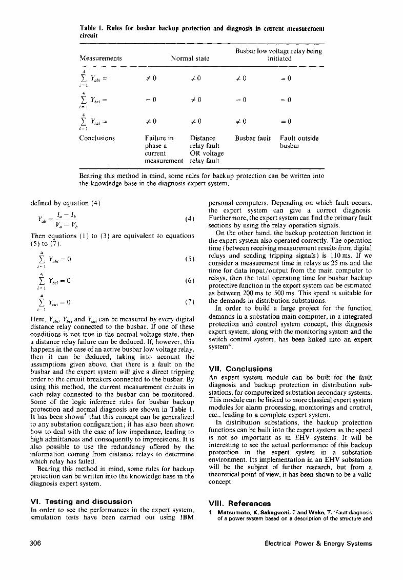
Table 1. Rules for busbar backup protection and diagnosis in current measurement circuit
Busbar low voltage relay being Measurements Normal state initiated
4
E Yabl = ¢ 0 ¢ 0 # 0 = 0 i = 1
4
E Y~c,= = 0 ¢ o = 0 = 0 i = 1
4
~.. Yc.,= # 0 # 0 # 0 = 0 ~=~
Conclusions Failure in Distance Busbar fault Fault outside phase a relay fault busbar current OR voltage measurement relay fault
Bearing this method in mind, some rules for backup protection can be written into the knowledge base in the diagnosis expert system.
defined by equation (4)
1 a - - I b Y.b - (4)
v o - v ~
Then equations (1) to (3) are equivalent to equations (5) to (7).
4
Y.b, = 0 (5) i = 1
4-
Y. Ybc, = o (6) i=1
4 Y~., = 0 (7)
i = 1
Here, Yabi, Ybci and Yc,i can be measured by every digital distance relay connected to the busbar. If one of these conditions is not true in the normal voltage state, then a distance relay failure can be deduced. If, however, this happens in the case of an active busbar low voltage relay, then it can be deduced, taking into account the assumptions given above, that there is a fault on the busbar and the expert system will give a direct tripping order to the circuit breakers connected to the busbar. By using this method, the current measurement circuits in each relay connected to the busbar can be monitored. Some of the logic inference rules for busbar backup protection and normal diagnosis are shown in Table 1. It has been shown 5 that this concept can be generalized to any substation configuration; it has also been shown how to deal with the case of low impedance, leading to high admittances and consequently to imprecisions. It is also possible to use the redundancy offered by the information coming from distance relays to determine which relay has failed.
Bearing this method in mind, some rules for backup protection can be written into the knowledge base in the diagnosis expert system.
VI. Testing and discussion In order to see the performances in the expert system, simulation tests have been carried out using IBM
personal computers. Depending on which fault occurs, the expert system can give a correct diagnosis. Furthermore, the expert system can find the primary fault sections by using the relay operation signals.
On the other hand, the backup protection function in the expert system also operated correctly. The operation time (between receiving measurement results from digital relays and sending tripping signals) is l l0ms. If we consider a measurement time in relays as 25 ms and the time for data input/output from the main computer to relays, then the total operating time for busbar backup protective function in the expert system can be estimated as between 200 ms to 500 ms. This speed is suitable for the demands in distribution substations.
In order to build a large project for the function demands in a substation main computer, in a integrated protection and control system concept, this diagnosis expert system, along with the monitoring system and the switch control system, has been linked into an expert system 4.
VII. Conclusions An expert system module can be built for the fault diagnosis and backup protection in distribution sub- stations, for computerized substation secondary systems. This module can be linked to more classical expert system modules for alarm processing, monitorings and control, etc., leading to a complete expert system.
In distribution substations, the backup protection functions can be built into the expert system as the speed is not so important as in EHV systems. It will be interesting to see the actual performance of this backup protection in the expert system in a substation environment. Its implementation in an EHV substation will be the subject of further research, but from a theoretical point of view, it has been shown to be a valid concept.
VIII. References 1 a a t s u r n o t o , K, S a k a g u c h i , T and Wake, T. 'Fault diagnosis
of a power system based on a description of the structure and
306 Electrical Power & Energy Systems

function of the relay system' Expert System Vol 2 No 3 (1985) pp 134-138
2 Fukui, C and Kawekami, J 'An expert system for fault section estimation using information from protective relays and circuit breakers" IEEE Trans Power Systems Vol PWRD-1 No 4 ( 1986 ) pp 83-90
3 Borland Internat ional Inc Turbo Prolog: Owner's Handbook (1986) Scotts Valley, CA
4 Trecat, J and Wang, J "Expert system applications on substation monitoring, backup protection and control' Fourth Int Conf in Development in Power System Protection April 1989 lEE Publications 302, pp 75-79
5 El Mernissi, A, Trecat, J and Maun, J C 'Monitoring and back-up protection of a busbar using digital distance relays' Proc 9th PSCC Cascais, Portugal, 1987 pp 751-757
Vo l 13 No 6 December 1 991 307