Embed Size (px)
Citation preview
An expert system for preliminary numerical design modelling K. J. M A C C A L L U M and A. D U F F Y
CAD Centre, University o f Strathclyde, Glasgow, G40NG Scotland
INTRODUCTION
From the earliest days of Computer Aided Design (CAD) there has been a clear recognition that establishing effective communication between the computer and the designer is crucial to the development of a productive design system. Early papers on the philosophy and concepts of CAD stated quite clearly that man and machine had to work together in a co-operative environment; and a few systems were developed to show the potential of this kind of approach. A fine example of the appreciation of this potential is given in a paper by Robert Mann and Steve Coons in 1965 (1). In this paper, they state: 'It is clear that what is needed if the computer is to be of greater use in the creative process, is a more intimate and continuous inter- change between man and machine. This interchange must be of such a nature that all forms of thought that are con- genial to man, whether verbal, symbolic, numerical, or even graphical are also understood by the machine and are acted upon by the machine in ways that are appropriate to man's purpose.' The emphasis on the computer's under- standing of man's purpose and on communication at the level of thought are significant.
Despite the early suggestions, an examination of devel- opments in CAD systems leads to the conclusion that the greatest advances in the application of computers to engin- eering design have been the assistance in 'number crunch- ing' for design analysis, and the development of specialised systems for limited design tasks. Parallel improvements in man-machine communication have been achieved through improved availability and accessibility of computing power and significant advances in computer graphics, providing a more acceptable medium for exchange of information. However, even those advances have not made significant in- roads into the problems of advanced communication. Only recently with increasing emphasis on product modelling has there been a gradual awareness that CAD systems require a much deeper level of user knowledge and problem know- ledge than is currently normal. It would seem, therefore, that much of the early potential of CAD has not yet been realised.
The work described in this paper addresses itself to this goal. It is argued that progress towards the goal can only be made by building into design systems a greater understand- ing of man's purpose. The key to this is to build systems which have explicit knowledge and are able to manipulate that knowledge and reason with it. The concept of 'expert systems' is built on this approach. This paper describes a
From the Proceedings of Engsoft IV, June 1985, Kensington, London, UK. Published by Springer-Verlag and Computational Mechanics Publications
system called DESIGNER which is an expert system con- cerned with building and handling knowledge of numerical relationships in preliminary design. The system is illustrated an evaluated using examples from preliminary ship design.
THE NATURE OF THE DESIGN PROCESS
Before looking at ways of representing design knowledge, it is worthwhile examining the design process itself in order to understand what contribution we can expect computers to make. A key characteristic of much of engineering design is the complexity of the objects or systems of interest. Typic- ally, a system will have many components, each of which will be related in different ways to other components through their characteristics. A designer's task is to create a specification for such a system, given a set of required functional objectives to be achieved in a given environment. The designer will rely on measures of performance, both objective and subjective, to select the most promising con- cepts for evaluation. However, complexity prevents the designer evaluating all concepts in detail; instead the design is broken down into parts and each part is tackled in a number of stages corresponding to levels of detail. Earlier stages have the least detail and use only the parameters which have the greatest influence on the overall design per- formance, whereas later stages operate within the constraints of previously defined parameters. A crucial feature of this approach is that individual stages are more tractable be- cause the number of independent parameters and their interactions are reduced.
A conclusion which can be drawn from this brief descrip- tion of the design process is that a designer's first expres- sions of concepts are in terms of objects, their character- istics, and the relationships which exist among them. One way of viewing design is as a process of modelling in which the above expressesions constitute the model. Thus in every situation the designer creates some kind of abstract model which simulates some aspect of the behaviour of the thing being designed. In fact it is likely that, for each concept, the designer handles a variety of models simultaneously, each one representing a different abstraction, but being consistent with the other. The models are essentially mental models but will be formalised through graphical, numerical, logical, and physical means. The creation of a model, which is a process of synthesis, is difficult to formalise. Evaluation of a particular model, however, is a process of analysis. It requires effort and sometimes ingenuity; but in most cases the procedures of evaluation are well defined. The overall design process involves establishing and collecting a variety of models, interchanging synthesis and analysis, and allow- ing interaction between design objectives and model speci- fications (2).
0141-1195/86/040217--06 $2.00 © 1986 Computational Mechanics Publications Adv. Eng. Software, 1986, VoL 8, No. 4 217

In summary it is useful to identify some important char- acteristics of the design process:
(a) creative - it requires imagination and inventiveness to build conceptual models. As a result of creative activ- ities, the form and structure of these models may change or develop as the design proceeds.
(b) multiple so lu t ions- there can be many answers to a given design problem, all of which may achieve the objectives, and may thus be technically and economic- ally feasible. Thus the design process is not deterministic.
(c) empir ica l - the process of creating and evaluating a model does not always follow well formalised rules with good theoretical bases. Very often relationships are of an empirical nature.
(d) approx ima te - because design is a modelling process which uses empirical relationships, the results obtained are generally approximate. Accuracy increases as the design proceeds and greater levels of detail are included. However, the concepts of expected and acceptable accuracy are important to the designer.
(e) requires exper t i se - the designer uses his expertise in many different ways during design, with respect to relationships used, the actual design process, and even in the judgment of the acceptability of proposed solutions.
These characteristics are most in evidence at the creative or preliminary stages of design during which basic concepts are being developed. However, the same characteristics are the ones which in many senses are the most difficult to computerise, involving intuition, experience, approximation and empiricism. It is hardly surprising, therefore, that con- ventional approaches of CAD to the creative stage of design have had limited success.
EXPERT SYSTEMS APPROACH
One of the most promising developments in the use of computers in recent years has been the work on expert systems (3). Its significance is that it addresses itself to providing computer systems which are able to make a 'knowledgeable' contribution to complex problems in a specific domain or field of interest, that is, to act as an 'expert'. A human expert is someone who has a specialised body of knowledge and is able to apply it to solve prob- lems, to advise, to act as a consultant, and to communicate his knowledge with others. An expert system is a computer system which is able to enact a similar role. The major ad- vance of expert systems compared to more conventional software systems is the explicit representation and mani- pulation of a body of knowledge. The 'knowledge base' can be used by the system in solving problems, in its own area of relevance, and can be added to directly by the human expert or by the system itself.
There are several important features in expert systems which make them capable of tackling problems of great complexity. The first of these is a description and re- presentation of knowledge in some formalised language. This immediately makes the knowledge base available and understandable to its users, and allows experts to examine and modify the system's knowledge as new situations are encountered. The second important feature is the system's ability to reason using a combination of known facts and generalised relationships in the knowledge base. Because the reasoning mechanisms and their control can be struc-
tured separetely from the knowledge base it is easier to express problems for solution. A third feature is the sys- stem's ability to provide explanations of the steps taken to reach a conclusion. This follows naturally from the forma- lised representation of the knowledge.
While many simple expert systems have used the know- ledge representation and control techniques adopted in earlier successful research work (4), there are still many areas of concern for the longer term development of expert systems. Some of these are the representations for new types of knowledge such as common-sense knowledge and uncertainty, required depth of knowledge, control over the use of knowledge, and the use of logic systems.
Michie (3) has identified three different user modes for an expert system in contrast to the single mode (getting answers to a problem) typical of the more familiar type of computing:
(a) user as a c l i en t - system acts as a consultant from whom the user wishes to get answers to problems.
(b) user as a t u t o r - system accepts instructions from a domain specialist to improve or refine its knowledge.
(c) user as a pupil - system can use its expert knowledge to instruct users in certain approaches.
To these three modes it is probably useful to add a fourth:
(d) user as an assistant- system interacts with user to encourage user to Fred a solution to a problem with guidance advice and stimulation from the system.
It is this last mode which is most relevant to the design situation. The work described in this paper is based on the contention that the approaches being taken in expert systems provides a key to realising the potential of CAD. For many years now we have been building complex CAD systems which contain increasing amounts of knowledge. However, that knowledge has been highly constrained to particular methods, and has been implicitly rather than explicitly available. Systems based on ideas of explicit knowledge representation and reasoning, offer the pos- sibility of greater productivity in the contribution they make to man-machine communication.
A DESIGN ASSISTANT FOR NUMERICAL DESIGN
From the discussion of the previous section it is concluded that any system which intends to take a more active role in a design dialogue must have the following features:
- a powerful semantically rich interface - a highly flexible design modelling and modification
system - an understanding (at least superficially) of design con-
cepts and goals - a capability for abstraction - a method of capturing and using expertise in a useful
way - an ability to expalin its own reasoning processes.
While we are still some way from achieving all these features, they indicate the direction of recent design system trends.
This section decribes an approach to creating a design assistant for numerical design based on this philosophy. The system, called DESIGNER was constructed to meet the following requirements:
218 Adv. Eng. Soflware, 1986, Vol. 8, No. 4
(a) flexible representation of user's design models; (b) ability to modify models, adding new design para-
meters or relationships, during the design process; (c) ability to represent designer's expertise with respect to
numerical modelling; (d) provide feedback to the designer on the nature of
relationships implied by a model; and (e) variety of levels of control of the design process by the
designer.
The requirements place emphasis on providing adequate knowledge representations and control rather than on the user interface. Thus the system will be described in terms of its knowledge structure before providing methods and examples of use.
1. A Network Model of Design
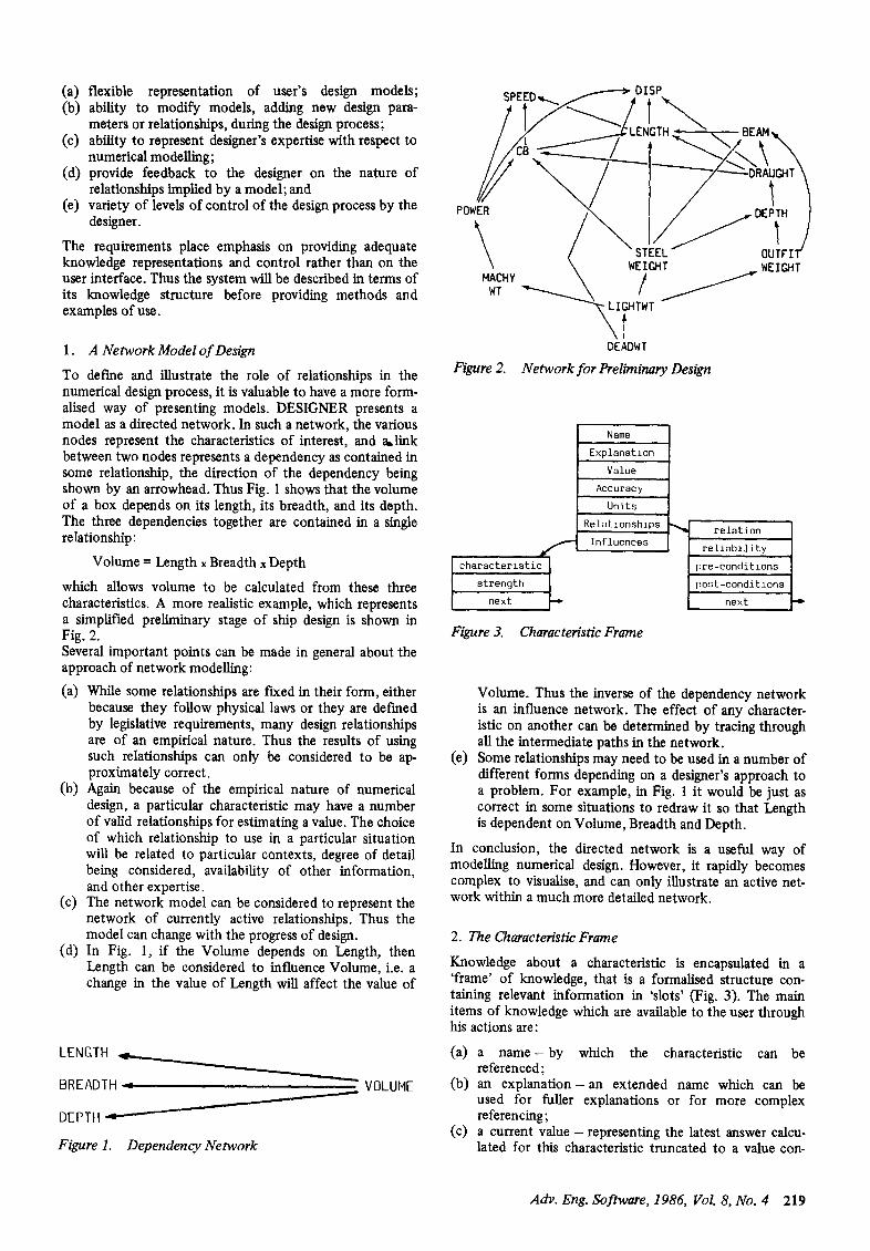
To define and illustrate the role of relationships in the numerical design process, it is valuable to have a more form- alised way of presenting models. DESIGNER presents a model as a directed network. In such a network, the various nodes represent the characteristics of interest, and a~link between two nodes represents a dependency as contained in some relationship, the direction of the dependency being shown by an arrowhead. Thus Fig. 1 shows that the volume of a box depends on its length, its breadth, and its depth. The three dependencies together are contained in a single relationship:
Volume = Length x Breadth x Depth
which allows volume to be calculated from these three characteristics. A more realistic example, which represents a simplified preliminary stage of ship design is shown in Fig. 2. Several important points can be made in general about the approach of network modelling:
(a) While some relationships are £Lxed in their form, either because they follow physical laws or they are defined by legislative requirements, many design relationships are of an empirical nature. Thus the results of using such relationships can only be considered to be ap- proximately correct.
(b) Again because of the empirical nature of numerical design, a particular characteristic may have a number of valid relationships for estimating a value. The choice of which relationship to use in a particular situation will be related to particular contexts, degree of detail being considered, availability of other information, and other expertise.
(c) The network model can be considered to represent the network of currently active relationships. Thus the model can change with the progress of design.
(d) In Fig. 1, if the Volume depends on Length, then Length can be considered to influence Volume, i.e. a change in the value of Length will affect the value of
LENGTH
BREADTH
DEPTH.t---------
Figure 1. Dependency Network
VOLUME
SPEED ~...,. ~ , , D IiP,,.
DEADWT Figure 2. Network for Preliminary Design
f characteristic L strength
next
Figure 3.
Name
Explanat ion
Value
Accuracy
Units
Relat ionships
Inf luences
Characteristic Frame
--~ relotion l I reliability I pre-conditions [post-conditions
next
Volume. Thus the inverse of the dependency network is an influence network. The effect of any character- istic on another can be determined by tracing through all the intermediate paths in the network.
(e) Some relationships may need to be used in a number of different forms depending on a designer's approach to a problem. For example, in Fig. 1 it would be just as correct in some situations to redraw it so that Length is dependent on Volume, Breadth and Depth.
In conclusion, the directed network is a useful way of modelling numerical design. However, it rapidly becomes complex to visualise, and can only illustrate an active net- work within a much more detailed network.
2. The Characteristic Frame
Knowledge about a characteristic is encapsulated in a 'frame' of knowledge, that is a formalised structure con- taining relevant information in 'slots' (Fig. 3). The main items of knowledge which are available to the user through his actions are:
(a) a n a m e - b y which the characteristic can be referenced;
(b) an explanat ion- an extended name which can be used for fuller explanations or for more complex referencing;
(c) a current value - representing the latest answer calcu- lated for this characteristic truncated to a value con-
Adv. Eng. Software, 1986, Vol. 8, No. 4 219
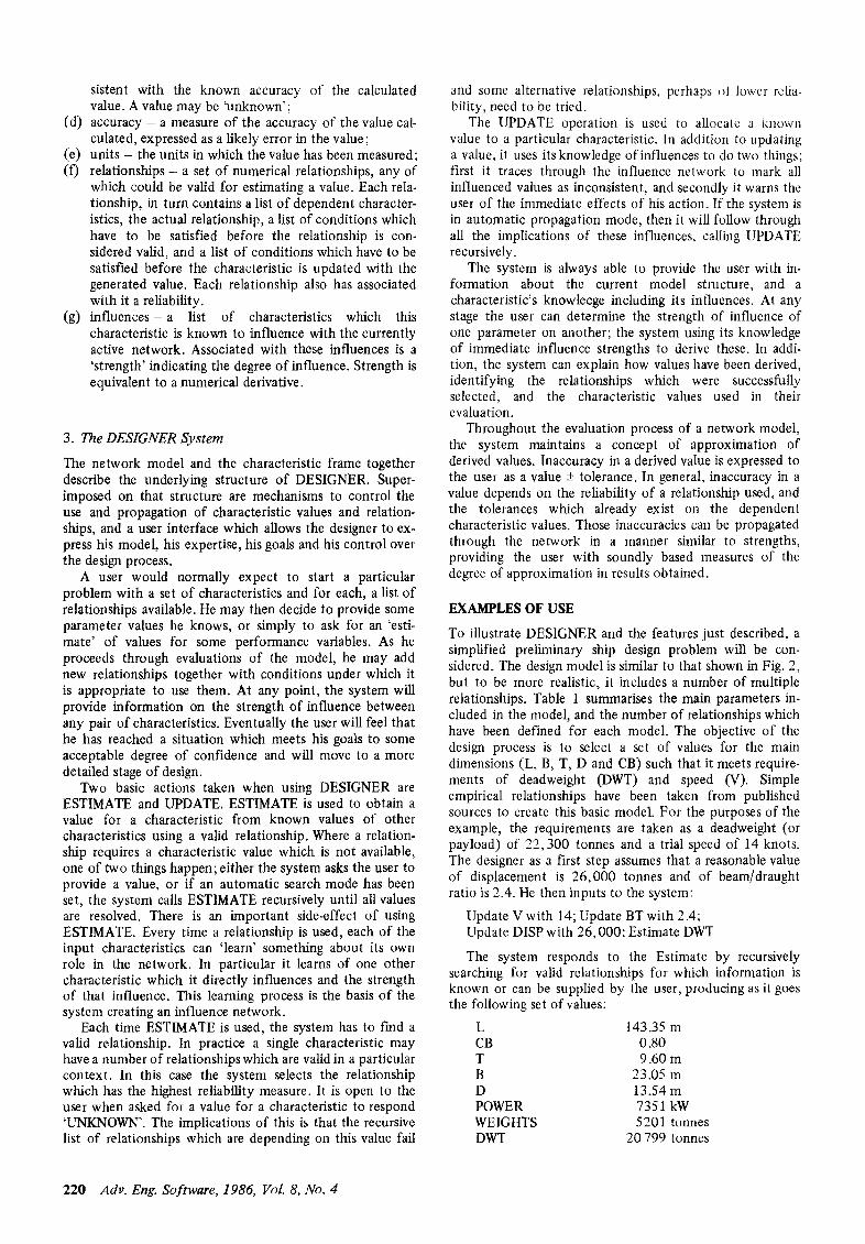
sistent with the known accuracy of the calculated value. A value may be 'unknown';
(d) accuracy - a measure of the accuracy of the value cal- culated, expressed as a likely error in the value ;
(e) units - the units in which the value has been measured; (f) relationships - a set of numerical relationships, any of
which could be valid for estimating a value. Each rela- tionship, in turn contains a list of dependent character- istics, the actual relationship, a list of conditions which have to be satisfied before the relationship is con- sidered valid, and a list of conditions which have to be satisfied before the characteristic is updated with the generated value. Each relationship also has associated with it a reliability.
(g) in f luences -a list of characteristics which this characteristic is known to influence with the currently active network. Associated with these influences is a 'strength' indicating the degree of influence. Strength is equivalent to a numerical derivative.
3. The DESIGNER System
The network model and the characteristic frame together describe the underlying structure of DESIGNER. Super- imposed on that structure are mechanisms to control the use and propagation of characteristic values and relation- ships, and a user interface which allows the designer to ex- press his model, his expertise, his goals and his control over the design process.
A user would normally expect to start a particular problem with a set of characteristics and for each, a list of relationships available. He may then decide to provide some parameter values he knows, or simply to ask for an 'esti- mate' of values for some performance variables. As he proceeds through evaluations of the model, he may add new relationships together with conditions under which it is appropriate to use them. At any point, the system will provide information on the strength of influence between any pair of characteristics. Eventually the user will feel that he has reached a situation which meets his goals to some acceptable degree of confidence and will move to a more detailed stage of design.
Two basic actions taken when using DESIGNER are ESTIMATE and UPDATE. ESTIMATE is used to obtain a value for a characteristic from known values of other characteristics using a valid relationship. Where a relation- ship requires a characteristic value which is not available, one of two things happen; either the system asks the user to provide a value, or if an automatic search mode has been set, the system calls ESTIMATE recursively until all values are resolved. There is an important side-effect of using ESTIMATE. Every time a relationship is used, each of the input characteristics can 'learn' something about its own role in the network. In particular it learns of one other characteristic which it directly influences and the strength of that influence. This learning process is the basis of the system creating an influence network.
Each time ESTIMATE is used, the system has to find a valid relationship. In practice a single characteristic may have a number of relationships which are valid in a particular context. In this case the system selects the relationship which has the highest reliability measure. It is open to the user when asked for a value for a characteristic to respond 'UNKNOWN'. The implications of this is that the recursive list of relationships which are depending on this value fail
and some alternative relationships, perhaps ~t lower relia- bility, need to be tried.
The UPDATE operation is used to allocate a known value to a particular characteristic. In addition to updating a value, it uses its knowledge of influences to do two things; first it traces through the influence network to mark all influenced values as inconsistent, and secondly it warns the user of the immediate effects of his action. If the system is in automatic propagation mode, then it will follow through all the implications of these influences, calling UPDATE recursively.
The system is always able to provide the user with in- formation about the current model structure, and a characteristic's knowlecge including its influences. At any stage the user can determine the strength of influence of one parameter on another; the system using its knowledge of immediate influence strengths to derive these. In addi- tion, the system can explain how values have been derived, identifying the relationships which were successfully selected, and the characteristic values used in their evaluation.
Throughout the evaluation process of a network model, the system maintains a concept of approximation of derived values. Inaccuracy in a derived value is expressed to the user as a value + tolerance. In general, inaccuracy in a value depends on the reliability of a relationship used, and the tolerances which already exist on the dependent characteristic values. Those inaccuracies can be propagated through the network in a manner similar to strengths, providing the user with soundly based measures of the degree of approximation in results obtained.
EXAMPLES OF USE
To illustrate DESIGNER and the features just described, a simplified preliminary ship design problem will be con- sidered. The design model is similar to that shown in Fig. 2, but to be more realistic, it includes a number of multiple relationships. Table 1 summarises the main parameters in- cluded in the model, and the number of relationships which have been defined for each model. The objective of the design process is to select a set of values for the main dimensions (L, B, T, D and CB) such that it meets require- ments of deadweight (DWT) and speed (V). Simple empirical relationships have been taken from published sources to create this basic model. For the purposes of the example, the requirements are taken as a deadweight (or payload) of 22,300 tonnes and a trial speed of 14 knots. The designer as a first step assumes that a reasonable value of displacement is 26,000 tonnes and of beam/draught ratio is 2.4. He then inputs to the system:
Update V with t4; Update BT with 2.4; Update DISP with 26,000; Estimate DWT
The system responds to the Estimate by recursively searching for valid relationships for which information is known or can be supplied by the user, producing as it goes the following set of values:
L 143.35 m CB 0.80 T 9.60 m B 23.05 m D 13.54 m POWER 7351 kW WEIGHTS 5201 tonnes DWT 20 799 tonnes
220 Adv. Eng. Software, 1986, Vol. 8, No. 4
Table 1. Key parameters and number of relationships
No. of Symbol Explanation relationships
B Moulded beam 4 BT Beam/draft Iatio 1 CB Block coefficient 2 D Moulded depth 3 DISP Moulded dispheement 1 DWT Full deadweight 1 GM Initial stability 1 L LBp 4 POWER Shaft power 1 T Draught 3 V Trial speed 0 WEIGHTS Lightship mass 1
The system's explanation of how these values were derived shows the specific relationships which were used. Alternatively, the system could be required to print out its search process as it goes along. An extract from this is given below:
ESTIMATE PHYS BEING TRIED
B DEPENDS ON [DISP L T CB]
T ESTIMATE PHYS BEING TRIED
T DEPENDS ON [DISP L B CB] B CURRENTLY BEING ESTIMATED THIS RELATIONSHIP NOT SUITABLE
SOLVE BEING TRIED T DEPENDS ON [DISP L BT CB]
CB ESTIMATE EMP BEING TRIED
CB DEPENDS ON [V El
ESTIMATE OF CB IS 0.80
OF T IS 9.60
OF B IS 23.05
It is worthwhile noting in this case the failure of valid relationships because of lack of information, followed by an attempt with an alternative relationship. The names of the relationships being tried have been provided during the def'mition of the model.
The overall result from this first estimate is that the deadweight is too low by about 1 500 tonnes. Using the strengths feature, the system reveals that an increase in deadweight of about 1 500 tonnes could be achieved by in- creasing DISP by about 1 750 tonnes. The effect of changing beam/draught ratio is negligible. Thus DISP can be 'UP- DATED' to 27 700. Normally the system will respond by warning the user of the immediate influences of this up- date; in this case:
The follwing will be affected by DISP
Deadweight B T L
If the automatic propagation mode was set then these im- mediate influences would be followed through making the
remainder of the network consistent. Alternatively, the user can again ask for deadweight to be estimated. In this case the overall effect will be the same and a value of deadweight of 22, 258 tonnes is produced.
As yet no unreliabilities have been mentioned, even though they should be associated with the relationships being used. If these are included using data from a range of available vessels then the latest set of values printed out would have read:
L CB T B D POWER WEIGHTS DWT
146.41 + 4.39m 0.80 +- 0.02 9.79 + 0.21m
23.50 -+ 1.1 lm 13.81 -+ 0.75m 7652 -+ 1056 kW 5442 + 668 tonnes
22258 +- 668 tonnes
With this level of approximation in the relationships, the deadweight requirement is well within the bounds of the answer.
The design process continues with an estimate of stab- ility (GM). The value of 1.69 -+ 0.93m is unsatisfactory and so further changes are required. The designer finds from the system that beam/draught ratio, and beam and draught themselves are the parameters which most influence GM. However, he feels that beam should not increase and thus decides to achieve his requirements of GM by changing draught, and keep his deadweight requirement by changing Length. The f'mal set of values is:
L 151.32m CB 0.81 + 0.02 T 9.50m B 23.50m D 13.39 +- 0.67m POWER 7731 +- 1033 kW WEIGHTS 5629-+ 658 tonnes DWT 22288 -+ 658 tonnes GM 1.95 +-- 0.92
It is of interest to note that this last sequence of operations changed the independent variables from beam/draught ratio and displacement to length, beam and draught. Thus the relationships used and consequently the network of dependencies and influences has changed. A second point of note is that a change now to one of the independent vari- ables in automatic propagation mode would result in both deadweight and GM being updated. This is now a different effect from just 'estimating' deadweight, which would leave GM as inconsistent.
DISCUSSION
This paper has been concerned with presenting an overall knowledge-based approach to handling numerical relation- ships in the preliminary stages of design. The last section illustrated the system by stepping through a simple ship design example. A number of features of the system were not presented since the aim was simply to convey the 'flavour' of the system and to illustrate the overall concepts involved. However, it is worth emphasising a number of points with respect to the DESIGNER system and examples used:
(a) there is complete flexibility to set up large varieties of design models; i.e. there is nothing in the DESIGNER system which is related specifically to ship design;
Adv. Eng. Software, 1986, Vol. 8, No. 4 221
(b) the user of the system has a large degree of control over the process of design, both in terms of the se- quence of steps and the rate of progress;
(c) in def'ming the model for the example, there were no assumptions made about what information would be available; neither were there assumptions about the way the user would approach the design process;
(d) the system uses built-in expertise to look for suitable relationships. Thus, only a part of the total model def'mition is active at one time;
(e) the system learns about influences and strengths of influence through the use of the model. The results of this can be used to provide guidance to the user about possible solution areas.
Despite the achievements of the system a taking a step to- wards a more knowledgeable design assistant, there are a number of areas in which research is still required:
(a) the present system deals only with numerical relation- ships. The other major aspect in any early design con- siderations is spatial arrangement. Although the present system allows graphical output of design trends or geometric representations, it cannot be considered to 'know' about spatial arrangements in the same way that it knows about characteristics;
(b) the major focus of attention has been to provide a flexible and rich set of facilities for handling numerical design problems, Little attention has been given to providing the most effective interface for handling this knowledge-based system;
(c) because of the complexity of the system careful study needs to be given to providing the correct level of corn-
munication between the human designer and the DESIGNER system. This is more than just an interface problem; it implies a deeper modelling of the user and the system;
(d) any long term accumulation of expertise by the system relies on relationships provided by designers. There should be links to design databases which would allow relationships to be extracted and added to the system.
CONCLU~ONS
It has been stated that CAD still has considerable potential for advancing the process of design, and that recent develop- ments in expert systems and knowledge-based systems cur- rently hold the key to releasing some of that potential.
A system, called DESIGNER which is based on these developments has been presented. This demonstrates a number of features which are normally difficult to achieve in more conventional CAD systems. However, there are clearly many areas which require further research and development.
REFERENCES
1 Mann, R. W. and Coons, S. A. Computer Aided Design, McGraw- Hill Yearbook Science and Technology, McGraw-Hill, 1965
2 MaLhotra, A., Thomas, J. C., Carroll, J. M. and Miller, L. A. Cognitive processes in design, Int. Journal of Man-Machine Studies, 1980, 12
3 Michie, D. Expert systems, Computer Journal, 1980, 23, 4 4 Alty, J. L. and Coombs, M. J. Expert Systems - Concepts and
Examples, N. C. C. Publications, 1984
222 Adv. Eng. Software, 1986, Vol. 8, No. 4