Embed Size (px)
Citation preview

An explicit ductile fracture model based on SMCS criterion for
large-scale FE-analysis of steel structures under cyclic loading
Makoto Ohsaki (Kyoto University)Jun Fujiwara (NIED)
Tomoshi Miyamura (Nihon University)

Purpose
• Develop a method for analysis of steel structures considering ductile fracture
• Applicable to large-scale FE-analysis of long-period motion (quasi-static cyclic deformation)
• Implicit integration and simple evaluation of stiffness degradation– Do not use small mesh– Do not allow explicit integration method with small
time increment

E-Simulator Project• Hyogo Earthquake Engineering Research Center (E-Defense) of
National Research Institute for Earth Science and Disaster Resilience (NIED), Japan
• WG of Building Frame• Platform for High-precision FE-analysis of steel frame
– Do not use macro model (plastic hinge, composite beam, column base, etc.)
– Utilize only material model and FE-mesh.– Simulate global and local responses simultaneously
• Investigation of collapse behavior of members and connections– Develop new devices for seismic control

Constitutive model
Material test
FE-model
High-precisionFE-analysis
Local responseGlobal response
Parallel computer
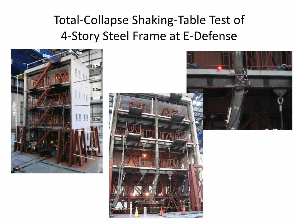
Total-Collapse Shaking-Table Test of4-Story Steel Frame at E-Defense

Details of FE-MeshHexahedral solid elementsLinear interpolation with
quadratic incompatible modes

Upper face of base
Bottom of columnRigid plate modeled by rigid beams
MPC (horizontal dir.)
Connection of anchor bolt: distributed nodes connected by rigid beams to prevent stress concentration
Anchor bolt (truss element)Connect base and upper face of base plateAxial force: 100 kN
Frictionless contact between base plate and base
Column (1st story)
Base beamBase plate
Mesh
FE-Model of Column Base

FE-Models• Spring model for exterior wall
Number of elements
Number of nodes
Number of DOF Column base Exterior wall
4,532,742 6,330,752 18,992,256 FE-model Spring

Equivalent Stress at the Maximum Deformation under Takatori wave
Whole frame Close view around the 2nd floor and the 1st story
Large stress is observed around the column base and beam-to-column connections.

Interstory drift angle of 1st story
X-direction
Analysis against 100% and 115% Takatori wave

Analysis against 100% and 115% Takatori wave
Interstory drift angle of 1st story
Y-direction

Equivalent stress (115%)
Ductile fracture is not considered

Seismic response analysis of 31-story steel building

X-Dir Y-Dir. X
Y
CAD Model


16/30
制震ブレース(トラス要素)
ガセット
FE-mesh
16
Gusset plate
Buckling restrained brace(truss element)

2nd floor
Base beam
Rigid plate
Node 24,765,275
Hex. Element 15,592,786
Rigid beam 78,686
Truss 372
Slave node 1,503,130
DOFs 74 million

18/30
0 1 2 3 4 5 6 7 8 9 10-300
-200
-100
0
100
200
300 max: 279.3
Time [s]
Accele
rati
on [
cm
/s2
]
UD
0 1 2 3 4 5 6 7 8 9 10-600
-400
-200
0
200
400
600
800
max: 605.5
Time [s]
Accele
rati
on [
cm
/s2
]
NS
NS
0 1 2 3 4 5 6 7 8 9 10-800
-600
-400
-200
0
200
400
600
800 max: 657
Time [s]
Accele
rati
on [
cm
/s2
]
EW
EW
UD
Y
JR-Takatori wave of Kobe Earthquake,1995.
18
NS

20/30
Equivalent stress at 3.5 sec.
Around core of 19th floor.
Magnification factor = 20
Yield stress
20

CFT (Concrete-Filled Tube) column
23Finite Element Mesh ModelFilled concreteSteel tube
Z
X
Y
Steel:Linear hexahedronIncompatible mode
Filled Concrete:Linear tetrahedron
Size of Elements:15-20 mm
Size of Mesh Model:122,320 nodes165,131 elements
Contact btw concrete and steel tube:
Out-of-plane: contactIn-plane: slip

-1,000
-500
0
500
1,000
-45 -30 -15 0 15 30 45
Horiz
onta
l Loa
d (k
N)
Horizontal Displacement (mm)
Experiment Analysis
24Cycles 15-18
Eq. plastic strain of steel tube
fcave of filled concrete
End of cycle 15
Local buckling of steel tube(Also in exp. Observed in cycle 15)
End of cycle 16
End of cycle 17
End of cycle 18

0
20
40
60
80
100
15 16 17 18 19 20
Cont
act P
ress
ure
(N/m
m2 )
Cycle
X-dir. Y-dir.
25
Contact Pressure at node 5078
Interaction between Steel Tube and Filled Concrete:
• X-dir.: Due to bending• Y-dir.: Due to plastic
deformation of concrete
Position of node 5078 Section at node 5078(End of Cycle 17)
Node 5078
105 mm
Top of base stub

Ductile fracture model for steel• Linear cumulative damage rule
– S-N curve, Minor’s rule, modified Minor’s rule– Not applicable to low-cycle fatigue (damage)
• Computational damage model– Gurson model: Damage due to void growth
• Mason-Coffin rule– Relation between strain amplitude and number of cycles
• Damage plasticity model– Mainly for concrete
• Fracture index– SMCS (stress modified critical strain) rule
• Two types of damage ductile damage/fracture model– Degradation before fracture / No degradation before fracture

Fracture without degradation
- Lemaitre, J. : A Course on Damage Mechanics, Springer-Verlag, pp.95-151, 1992- Dufalilly, J. and Lemaitre, J. : Modeling Very Low Cycle Fatigue, International, Journal of Damage Mechanics, Vol.4, pp.153-170, 1995
- Huang, Y. and Mahin, S. : Evaluation of Steel Structure Deterioration with Cyclic Damaged Plasticity, Proceedings of 14WCEE, 2008
: Damage parameter
( / ) for / 1 / 30 for / 1 / 3
: twice of elastic strain energy: equivalent stress, : mean stress
: plastic strain increment, , : parameter
t pm e
m e
e mp
D
Y SD
Y
S t
ε σ σσ σ
σ σ
ε
∆ > −∆ = ≤ −
∆
Fracture occurs if exceeds the specified value can be integrated explicitly/ =1/3 for uniaxial, 2/3 for biaxal tensionm e
DDσ σ

Gurson model
- A. Needleman and V. Tvergaard, Numerical modeling of the ductile-brittle transition, Int. J. Fracture, Vol. 101, pp. 73-97, 2000.
- A. L. Gurson, Continuum theory of ductile rupture by void nucleation and growth: Part I, Tield criteria and flow rules for porus ductile media, J. Eng. Material and Tech., ASME, Vol. 99, pp. 2-15, 1977.
2232 cosh [1 ( ) ] 0
: yield function, : yield stress without damage: equivalent stress, : mean stress
: volume ration of void, : parameter ( 1.5)
e m
Y Y
Y
e m
fq qf
f q
σ σφ
σ σφ σσ σ
= + − + =
=
Stiffness degradation due to void growth

Damage plasticity for concrete
- J. Lee and G. Fenves, Plastic-damage model for cyclic loading of concrete structures, J. Struct. Eng., Vol. 124(8), pp. 892-900, 1998.
0
0
: Isotropic damage degradarion parameter: Stress tensor, : Effective stress tensor
[1 / (1 )]: Initial elastic stiffness tensor(1 ) : Effective elastic stiffness tensor
: Elastic e
D
D
D
= −
= −
σ σσ σEE E
ε
0 0
strain tensor, (1 )e e eD= = = −σ E ε σ Eε E ε

Damage plasticity for concrete
( , , ) 0: Back stress tensor, : Size of yield surface
F κκ
=σ αα
Yield condition
ˆ ˆ( , , ) 0ˆ ˆ(1 ) , (1 )F
D Dκ
κ κ=
= − = −
σ αα α
Evolution rule for D based on principal stresses

Fracture index
: Mean stress, : Equivalent stress (von Mises stress)
: Stress triaxiality
(1/3 for uniaxial stress, 2/3 for uniform biaxal stress)exp( 1.5 ) : fracture strain
ˆ : accumlated
m e
m
e
c
p
T
T
σ σσσ
ε β
ε
=
= −
plastic stress for tension state 0mσ >
- J. W. Hancock and A. C. Mackenzie, On the mechanism of ductile failure in high-strength steels subjected to multi-axial stress-states, J. Mech. Phys. Solids, Vol. 24, pp. 147-169, 1976.
ˆFracture index =
p
c
εε

Fracture index
Fracture condition
ˆ exp( 1.5 )p c Tε ε β≥ = −ˆ ( exp(1.5 ) : deformation parameter)p Tα β α ε> =
0.5 ˆ ˆUniaxial tension: 1 / 3 1.649p pT eα ε ε= ⇒ = =
A. M. Kanvinde and G. G. Deierline, Void growth model and stress modified critical strain model to predict ductile fracture in structural steels, J. Struct. Eng., ASCE, Vol. 132(12), pp. 1907-1918, 2006.S. El-Tawil, E. Vidarsson, T. Mikesell and S. K. Kunnath, Inelastic behavior and design of steel panel zones, J. Struct. Eng, ASCE, Vol. 125, No. 2, pp. 183-193, 1999.

Damage model using fracture index
( )
( )
( )
( )
1
11 1 2
2 1
2 12 2 2 3
3 2
2 3
0
( ),
( )
D
DD D
D
α α
α α α α αα α
α α α α α αα α
α α
≤ − ≤ ≤ −= − + − ≤ ≤ −
≤
Bilinear relation
: damage parameter (fracture ratio)D
Piecewise linear relation
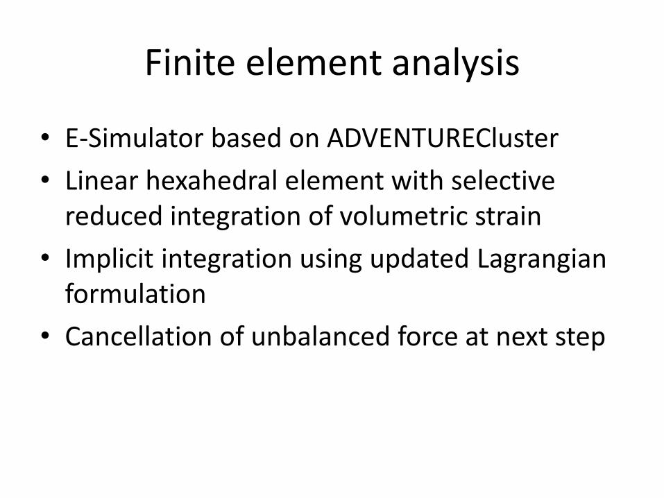
Finite element analysis
• E-Simulator based on ADVENTURECluster• Linear hexahedral element with selective
reduced integration of volumetric strain• Implicit integration using updated Lagrangian
formulation• Cancellation of unbalanced force at next step

Analysis of notched rod model
050
100150200250300350400450500
0 5 10 15
真応力
(MPa
)
真ひずみ (%)
実験値
Notched rod modelStress-strain relation(rod without notch)
- M. Obata, A. Mizutani and Y. Goto, The verification of plastic constitutive relation and its application to FEM analysis of plastic fracture of steel members, J. JSCE, No. 626/I-48, pp. 185-195, 1999. (in Japanese)

Parameter for fracture
α D1 0 02 0.0500 03 0.9250 0.0104 0.1370 0.0255 0.1672 0.0556 0.2110 0.1107 0.3298 0.2508 0.4947 0.600

Analysis of rod model
Notched rod model
60 mm
25 mm
Thickness = 12.7 mm
Unit size = 2.0 mm
No. Elements: 1824No. Nodes: 2443NDOF: 7329

Identification of material property
Logarithmic strain
Cau
chy
stre
ss
Relation without damage
0
0
(1 )log(1 ) : before neckinglog( / ) : after necking
: Cauchy stress: engineering stress: true strain: engineering strain: deformed area: undeformed area
t e e
et
t
e
t
e
A A
AA
σ ε σ
εε
σσεε
= +
+=

Force-displacement relation
∆ = 0.001, ζ = 10-8,
Fixed support
Forced disp. U
Small disp. U/100for imperfection

Force-displacement relation
∆ = 0.001, ζ = 10-5,∆ = 0.001, ζ = 10-8, imperfection
∆ = 0.0005, ζ = 10-3, imperfection Incompatible mode, ∆ = 0.001, ζ = 10-5,

Force-displacement relation
∆ = 0.001, ζ = 10-8∆ = 0.0001, ζ = 10-5
Unit size = 0.15625 mm,
Fracture at U = 1.2→ No significant mesh dependence→ No stress concentration

X-directional stress X-directional strain Equivalent stress
Equivalent plastic strain Damage ratio

Equivalent plastic strain Damage ratio
Damaged part
Undamaged part
Stain
Stre
ss
Stain
Stre
ss

Analysis of beam-column model
- D. Fukuoka, H. Namba and S. Morikawa, E-defense shaking table test for full scale steel building on cumulative damage by sequential strong ground motion (Part 2 Subassemblage Tests), Proc. Annual Symp. AIJ, Paper No. 22489, 2014.

Analysis of beam-column model

Analysis of beam-column modelPin support
Pin support
Forced displacement
No. Elements: 32244No. Nodes: 47679NDOF: 145638

Moment-angle relation

Conclusion of first part
• A method for analysis of steel structures considering ductile fracture
• Implicit integration and simple evaluation of stiffness degradation
• Cancellation of unbalanced force at next step • Application to notched beam and beam-column joint
• Analysis sometimes stops after fracture→Necessary to convert the total formulation to incremental form

Optimization approaches
• Mathematicalprogramming
• Population-based heuristicapproach
Geometrical/materialnonlinearity
High computationalcost
Poor convergence
Evaluate response many times
Tabu search:◆ single-point search heuristics based on local search◆ solution is always improved

• Optimize location and thickness of stiffeners• Increase plastic energy dissipation property• Prevent buckling and collapse near connections• FEM code: ABAQUS• Shell element: Thick shell with reduced
integration (S4R) • Forced vertical displacements
Outline of optimization
Boundary A Boundary B
Forced disp.
flange
web
stiffener

Ductile failure criteria• SMCS (stress modified critical strain)
(Chi, Kanvinde and Deierline, J. Struct Eng, ASCE, 2006)• Index for low cycle fatigue• Defined by stress triaxiality ( σm / σe)
• Decreasing function of triaxiality ( σm / σe )
• Fracture occurs if FI=1.0
• Compute FI of all elements and find the max. value
Equivalent plastic strainvon Mises equivalent stressMean stress
(sum of principal stresses / 3)
pε
Critical plastic strain:

Optimization problemObjective function
Plastic dissipated energyConstraint
Max. value If of FI is less than 1.0
Design variables– Location, thickness, and
angle of stiffeners– Discretize real variables
xi to integer variables Ji
–
振幅
[rad]
Rot
atio
n an
gle

Optimization using ABAQUS
Generate coordinates,thickness, length
TS Algorithm(1) Flange, web, plate parts(2) Material and section(3) Assemble beam part (4) Boundary and load(5) FE-mesh (6) Submit to ABAQUS
Preprocessing (Python Script)
Simulation ABAQUS/Standard
Postprocessing(Python Script)
Dissipated energyEquivalent plastic StrainCompute objective andconstraint functions

Optimization of location and thickness of stiffeners
Standard
Opt-1:(location)
Opt-2:(location and angle)
Standard Opt-1
Opt-2
Number of cycles before
failure
Dissipated energy before failure
Nf Epf
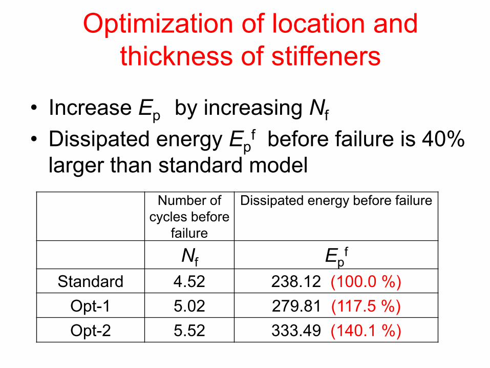
Standard 4.52 238.12 (100.0 %)Opt-1 5.02 279.81 (117.5 %)Opt-2 5.52 333.49 (140.1 %)
Optimization of location and thickness of stiffeners
• Increase Ep by increasing Nf
• Dissipated energy Epf before failure is 40%
larger than standard model

Force-rotation relation
Inelastic Rotation (rad)-0.08 -0.04 0 0.04 0.08
400300200100
0-100-200-300-400
Shea
rFor
ce(k
N)
StandardOpt-2

Analysis using solid elements(ADVENTURECluster)
Attach rotational springs of 4.0×10⁴MNm/rad at control nodesto simulate flexibility of support frames
Control node
Number of elements: 38,234 including 1,048 rigid barsNumber of nodes: 61,110Degrees of freedom: 184,128,

Constitutive rule of steel material• Piecewise linear combined hardening with von Mises
yield condition → Applicable to large-scale FE-analysis
• Incorporate yield plateau and Bauschinger effect → Different rules for first and second loadings
Stress-strain relation forfirst and second loading Simulation of cyclic material test

Detailed FE-analysis(fixed boundary)
Standard Optimal

Detailed FE-analysis(Rotational spring)
Standard Optimal
rotational spring

Detailed FE-analysis(rotational spring: first 2 cycles)
Standard Optimal