Embed Size (px)
Citation preview

48
Introduction
Outdoor field work such as geographic or archaeological surveying requires editing and processing of semantic information on spatial data. Currently these studies are performed manually using pen and printed maps or a laptop with a GPS receiver and digital two-dimensional (2D) maps. In many cases such as rescue excavations for urban archaeology or site surveys after flooding there is limited time before construction work starts and traditional techniques do not suffice.
In practice annotations are used to mark different layers and regions in civil engineering or stratigraphy studies. The processing time consists of manual work in the field and
digitizing afterwards. A laptop allows users to process digital data in the field but hinders walking around freely and requires constant switching between the laptop screen and the real world. This mental mapping process may lead to high error rates. In this paper we demonstrate improving the limitations of this workflow using hand-held mobile computers.
Hand-held mobile computers already have started replacing notebooks and desktops for many computing tasks in the field. These devices have several shortcomings, such as: limited battery life, small display area and limited user interaction. Solutions which have been optimized for desktop environment need to be carefully re-designed and extended in line with the requirements of the mobile work
An Image Based Modelling and Annotation Tool for Outdoor Cultural Heritage Studies
Mustafa Tolga ErenSabanci University, Turkey. [email protected]
Ceren Kayalar Sabanci University, Turkey. [email protected]
Selim BalcisoySabanci University, Turkey. [email protected]
Abstract: Many professional tasks such as archaeological or geographic surveying require editing and processing of semantic information on spatial data. Currently these studies are performed manually using pen and printed maps or a laptop with digital maps. In many cases such as excavations on urban archaeology sites there is limited time before construction work starts and traditional techniques do not suffice. We propose a workflow featuring a simple modelling and annotation authoring process. There are a few issues that need to be taken into consideration: 1) how to create 3D annotations and 2) how to visualize these annotations in a mobile context. In addition, our use cases require fast-generated and simple models that allow editing for annotation authoring. Annotations are then presented over these user generated models. Our contribution includes: 1) a novel annotation technique based on 3D geometric regions, and 2) a simple and image-based modelling workflow based on building blocks.
Key Words: Image-based Modelling, Annotation, Mobile Graphics

An Image Based Modelling and Annotation Tool for Outdoor Cultural Heritage StudiesMustafa Tolga Eren, Ceren Kayalar and Selim Balcisoy
49
environment. The main goal of this paper is to let the professionals perform the annotation task in the field successfully using a mobile device in minimum time.
We propose a workflow featuring a simple modelling and annotation authoring process. There are two major issues need to be taken into consideration: 1) how to create three dimensional (3D) annotations and 2) how to visualize these annotations in a mobile context. An annotation can be defined as adding extra virtual information over a real object (Wither et al. 2009). We extend this definition and employ a variety of annotation types ranging from a single point to four dimensional (4D) annotations, an annotation of a volume over time. In the context of this paper, the main goal of annotations is to identify the primary building blocks or layers of an object. Labels and text may not be enough for complete annotation authoring. Archaeologists and civil engineers are interested in layer-based studies such as stratigraphy. In order to annotate a layer of a 3D object correctly, a 2D label is not the best choice. A layer represents a volume of the object, so we propose a volume based annotation authoring process.
To visualize annotations, we utilize user generated 3D models as an underlying structure. These models are fast generated, and roughly represent the object. We do not require high precision models as we only need these models to lay annotations over them.
When dealing with static images, where the user only observes the scene from a single point, annotation authoring and management can be achieved using 2D constructs such as labels and floating text (Luan et al. 2008). On the other hand, in mobile context the user can freely move in the scene, thus he effectively changes the eye position. When the user moves, 2D constructs may start overlap or even become distorted and very hard to read. In order to handle annotation visualization for mobile users, an underlying
Figure 1. An urban scene is (a) photographed. Using these images, two objects are (b) modelled and (c) annotated using our workflow. Annotations are colour coded; a legend is shown in the canvas for identification (for full colour image please see the online version of this paper).

CAA2011 - Revive the Past: Proceedings of the 39th Conference in Computer Applications and Quantitative Methods in Archaeology, Beijing, China, 12-16 April 2011
50
3D structure is preferred, especially to handle occlusions by utilizing depth information (Kopf et al. 2008). Kopf et al. (2008) used high quality models and accompanying textures to visualize and annotate large scenes, such as Manhattan Island. Although the results are visually impressive, editing and processing of dense models on a mobile device may not be feasible. In addition, our use cases require fast-generated and simple models that allow editing for annotation authoring. To overcome these issues, we propose a simple and semi-automated image-based modelling process, where the user combines several building blocks in order to create a model. Annotations are then presented over these user generated models.
Our contribution includes: 1) a novel annotation technique based on 3D geometric regions, and 2) a fast modelling workflow based on building blocks. To best of our knowledge, this is the first method that applies volumetric annotations. We also introduce a simple and intuitive interface for modelling and annotation editing processes.
Related Work
Modelling
Object modelling is a well-researched topic in both computer graphics and vision. Geometric models can be created from scratch or sampled from real objects using a number of techniques. Many commercial 3D modelling packages support image based modelling tools, such as Blender (Blender 2005). These packages often support using top, side and front photograph views as superimposed over the model. There are also fully automated solutions based on computer vision techniques for creating models out of sets of images (Pollefeys et al. 2004). However, these are prone to artefacts caused by vision algorithms when fed with noisy or underexposed images. In order to deal with
these artefacts researchers adopted semi-automated processes such as PFTRACK and Vodoo (Debevec et al. 1996; PFTRACK 2010; Thormählen and Broszio 2010).
These approaches allow some user interaction; i.e. letting users manually mark corresponding features. VideoTrace by van den Hengel et al. (2007) is an improvement over semi-automated processes as it supports user-interacted geometry creation, however, it requires users to work within the VideoTrace environment. Like VideoTrace, Sinha et al.’s (2008) system makes use of the underlying sparse reconstruction, moreover they utilize vanishing directions. Recently Thormählen and Seidel (2008) presented an ortho-imaged based solution for creating high quality models without forcing modellers to leave their desired modelling environment. Other vision-based methods use large geo-tagged photo sets to generate textured 3D models of buildings (Grzeszczuk et al. 2009; Snavely et al. 2006; Xiao et al. 2008).
Annotations
Annotating real objects is heavily investigated under Augmented Reality (AR). Feiner et al. (1997) and Rekimoto and Nagao (1995) early works used AR to annotate the real world with overlaid textual labels. Although a 3D model is generally used to place annotations, Snavely et al. (2006) used a system to transfer annotations from one image to another. Recently Wither et al. (2009) and Wither and Höllerer (2005) investigated annotations in outdoor augmented reality domain. Another outdoor AR work by Schall et al. (2008), introduced an annotation authoring tool which creates 2D information labels in 3D coordinates. Visualization of annotations is also a popular research topic. Annotations can be associated with a 2D point (Azuma and Furmanski 2003) or a 3D position (Henderson et al. 2010) depending on the application. Generally if the virtual camera is mobile the 3D approach is preferred.

An Image Based Modelling and Annotation Tool for Outdoor Cultural Heritage StudiesMustafa Tolga Eren, Ceren Kayalar and Selim Balcisoy
51
Mobile Studies
Our modelling approach is inspired by image-based methods. Similar approaches have been utilized by Piekarski (2006) to create object models in the field using a backpack based system known as Tinmith-Endavour. MARS is another backpack-based system which also includes a hand-held device to annotate and view merged environments (Höllerer et al. 1999). To author physical models, Baillot et al. (2001) used mobile computers by generating 3D models from floor plans via user interaction. Backpack-based approaches offer computing power as well as centimetre accurate GPS sensors.
Although a backpack-based computer was required for these tasks in the past, currently hand-held computers are capable of performing even more complicated tasks (van den Hengel and Anton 2010). A recent work by Schall et al. (2008) focuses on displaying pre-defined 3D models to aid civil engineers using hand-held mobile devices. For on-site archaeological studies Benko et al. (2004) provided collaborative mixed reality visualization following data recording and archiving principles defined by Harris (1989).
Modelling
Our modelling process utilizes a “construction toy” analogy. The output of our modelling process is a combination of interlocked primitives. In order to create a complex model, user attaches 3D geometric primitives to each other, one at a time. These 3D geometric primitives are referred to as “building blocks” in the rest of the paper. For simplicity the variety of building blocks are kept at minimum i.e. cube, column, dome and cone. However for each building block the user is able to define an independent transformation. By utilizing these individual transformations it is possible to create many required primitives to model a building. Semi-automated approaches have
long been examined for image-based modelling processes.
In many of these approaches, the user is asked to match exact features in several images (Hartley 1997). More recently, VideoTrace (van den Hengel et al. 2007) allowed users to define polygons on video frames and these polygons are auto transformed with respect to camera positioning. Our approach lies in between; rather than letting the user match exact positions in several images, we ask the user to adjust an initial building block, incrementally fixing the orientation over several images. Additional building blocks inherit the orientation of this reference block. The final orientation is saved in a real world coordinate system. Using GPS and digital compass data associated with every reference image, we triangulate and find the estimated position for the real world objects.
The modelling process starts with inserting an initial building block to our scene. This block is translated, rotated and scaled by the user, to match a primitive of the object that is being modelled. Then the user is able to drag and drop the next desired building block to the scene. The new block is attached to the model when the user drops this building block onto any previous block. In this case the newly added block is automatically transformed and inserted to the scene hierarchy as a child of that previous block. The user may adjust the transformation via a simple graphical user interface (GUI). This process is repeated until the object is completely modelled.
The Building blocks can interlock each other at 26 different locations. These locations lay on the bounding box of each block. They consist of 8 corner points, 12 points in the middle of each corner pair and 6 face centres.
The interlocking process takes source and target blocks’ scale and an interlocking vector as input. For example if the user inserts a new block to the right side of a previous block, then
CAA2011 - Revive the Past: Proceedings of the 39th Conference in Computer Applications and Quantitative Methods in Archaeology, Beijing, China, 12-16 April 2011
52
the interlocking vector should have a positive value along the X axis, in particular this vector is v(1;0;0). To adjust the scale of the new block, the axes with a value of 0 are considered. Corresponding scale values on these axes are used to find the maximum ratio in between. The inverse of this ratio is used to scale down the new block. After auto-scaling, the new block is translated to the edge of the previous block to make the blocks look like they are interlocking. A newly added block carries the rotation of its parent.
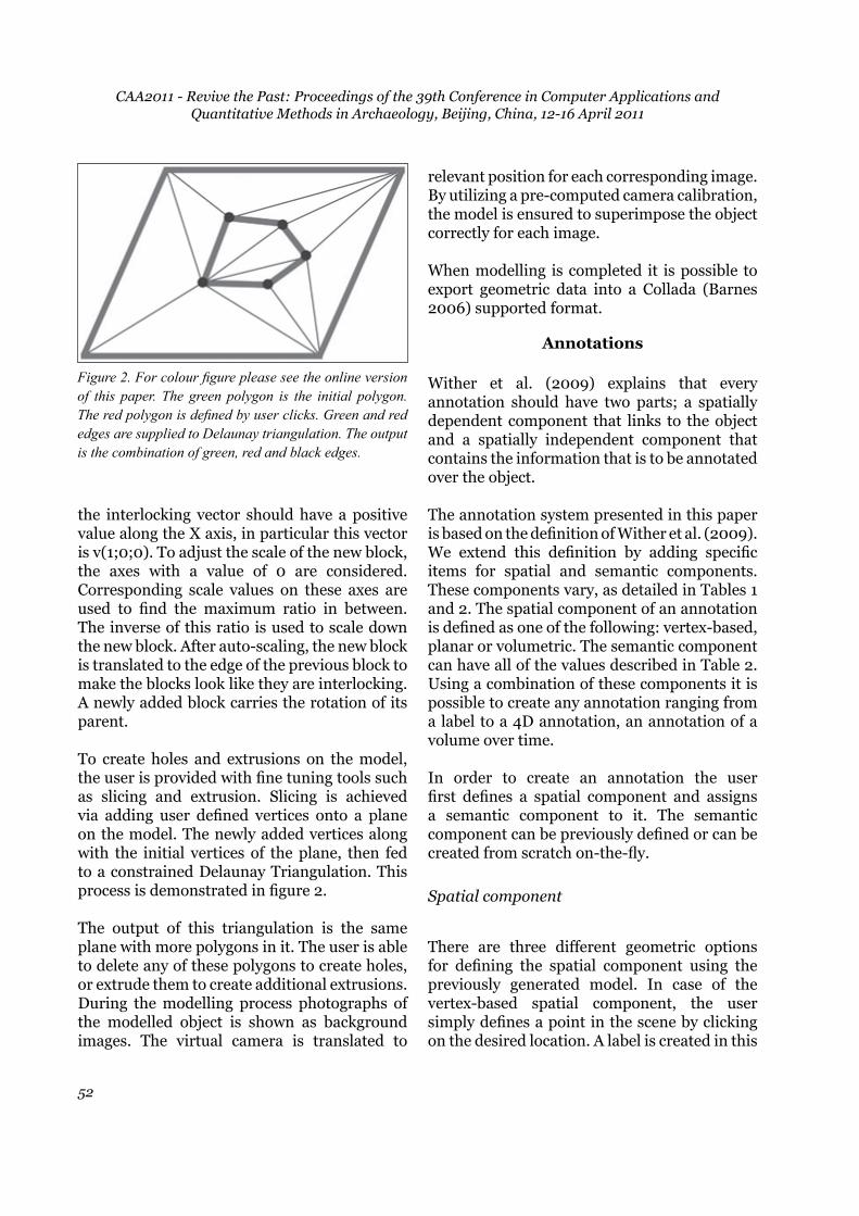
To create holes and extrusions on the model, the user is provided with fine tuning tools such as slicing and extrusion. Slicing is achieved via adding user defined vertices onto a plane on the model. The newly added vertices along with the initial vertices of the plane, then fed to a constrained Delaunay Triangulation. This process is demonstrated in figure 2.
The output of this triangulation is the same plane with more polygons in it. The user is able to delete any of these polygons to create holes, or extrude them to create additional extrusions. During the modelling process photographs of the modelled object is shown as background images. The virtual camera is translated to
relevant position for each corresponding image. By utilizing a pre-computed camera calibration, the model is ensured to superimpose the object correctly for each image.
When modelling is completed it is possible to export geometric data into a Collada (Barnes 2006) supported format.
Annotations
Wither et al. (2009) explains that every annotation should have two parts; a spatially dependent component that links to the object and a spatially independent component that contains the information that is to be annotated over the object.
The annotation system presented in this paper is based on the definition of Wither et al. (2009). We extend this definition by adding specific items for spatial and semantic components. These components vary, as detailed in Tables 1 and 2. The spatial component of an annotation is defined as one of the following: vertex-based, planar or volumetric. The semantic component can have all of the values described in Table 2. Using a combination of these components it is possible to create any annotation ranging from a label to a 4D annotation, an annotation of a volume over time.
In order to create an annotation the user first defines a spatial component and assigns a semantic component to it. The semantic component can be previously defined or can be created from scratch on-the-fly.
Spatial component
There are three different geometric options for defining the spatial component using the previously generated model. In case of the vertex-based spatial component, the user simply defines a point in the scene by clicking on the desired location. A label is created in this
Figure 2. For colour figure please see the online version of this paper. The green polygon is the initial polygon. The red polygon is defined by user clicks. Green and red edges are supplied to Delaunay triangulation. The output is the combination of green, red and black edges.

An Image Based Modelling and Annotation Tool for Outdoor Cultural Heritage StudiesMustafa Tolga Eren, Ceren Kayalar and Selim Balcisoy
53
location representing semantic component of this annotation.
For a planar spatial component, the user is able to select a face of any building block. It is also possible to adjust this selection by adding arbitrary points on the face to create a more detailed polygon on the model. This is achieved by inserting user defined vertices on the face and computing a constrained Delaunay triangulation.
In order to create a volumetric spatial component, the user needs to define a volume on the model. This process is simplified by utilizing clipping planes. The user creates the desired number of clipping planes to create a sub-section of the 3D model.
The volume which resides in between the clipping planes becomes the volumetric spatial
Figure 3. Illustration of the annotation creation process.
(a) The user observes a 3D model ready to be annotated. (b) For colour figure please see the online version of this paper. Red squares denote user clicked 3D positions. Using these two points and the position of the virtual camera, a clipping plane is calculated. With this clipping plane the 3D model is divided into two 3D volumetric regions. Green line is the contact region of these two regions. (c) A new volumetric region is generated using the same approach in Figure 3b. The user clicked points do not have to be on the same face. As long as they are located on the model geometry, a new clipping plane is calculated. (d) A final region is added. The created volumetric regions are associated with semantic components to create annotations. The annotations are presented in different colours and superimposed over the model.
Spatial component Description
Vertex-based A point in the scene
Planar A plane on the model
Volumetric A volume of the model
Table 1. The spatial components.
CAA2011 - Revive the Past: Proceedings of the 39th Conference in Computer Applications and Quantitative Methods in Archaeology, Beijing, China, 12-16 April 2011
54
component. Figures 3a through 3c illustrate this process.
Semantic component
A semantic component must have an ID and a colour, other fields are optional. When assigned to a vertex-based spatial component, an annotation is created as a label. The ID of the semantic component is displayed on this label
with the appropriate colour. When assigned to a planar or volumetric spatial component, the geometric region defined by the spatial component is coloured accordingly to create an annotation as seen in figure 3d. A legend is also displayed to identify coloured components on the canvas separately.
We use time as a variable to visualize annotations, in a chronologically ordered scene. As shown in figure 1, many urban settings contain visible objects from different eras; the user is able to observe annotations of these objects in chronological order by moving a time slider. As time progresses, relevant annotations simply fade in to the scene to superimpose the real world images. The annotation is active and visible only for the interval defined in the associated semantic component. A descriptive text is shown when the user clicks a specific annotation.
WorkflowandDesignChoices
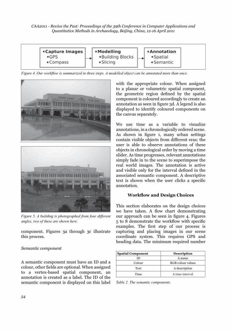
This section elaborates on the design choices we have taken. A flow chart demonstrating our approach can be seen in figure 4. Figures 5 to 8 demonstrate the workflow with specific examples. The first step of our process is capturing and placing images in our scene coordinate system. This requires GPS and heading data. The minimum required number
Figure 4. Our workflow is summarized in three steps. A modelled object can be annotated more than once.
Figure 5. A building is photographed from four different angles, two of these are shown here.
Spatial Component DescriptionID A name
Colour RGB colour values
Text A description
Time A time interval
Table 2. The semantic components.

An Image Based Modelling and Annotation Tool for Outdoor Cultural Heritage StudiesMustafa Tolga Eren, Ceren Kayalar and Selim Balcisoy
55
Figure 6. The modelling process starts with creating and adjusting a reference block. This block has the same orientation as the building.
Figure 7. The completed model is shown; in this example 6 blocks are used to model the entire building.
Figure 8. After generating volumetric regions as spatial components, four different annotations are created. These are, from top to down; 2nd floor, 1st floor, ground floor and basement.

CAA2011 - Revive the Past: Proceedings of the 39th Conference in Computer Applications and Quantitative Methods in Archaeology, Beijing, China, 12-16 April 2011
56
of images is one. However, capturing 2-5 images from different viewing angles produces better results. These images will be used as reference images in the application.
The next step is modelling. Reference images serve as background and a virtual camera is translated in order to represent the position of the real camera. The very first building block for each new object establishes a mapping from scene coordinates to object coordinates. We call this the reference block of the object. This reference block is the root of the object building block hierarchy. We save the orientation information and use it to place our model in real world coordinates by a simple triangulation process. The user can also translate the virtual camera to a pre-defined position such as the top view. This is similar to the approaches used by Piekarski and Thomas (2003). The user is now able to add new blocks to the scene using point and shoot analogy. The new block is attached to the user selected block along the interlocking vector. The interlocking vector is selected by clicking directly on the building block’s related area. Alternatively a pre-defined vector can be selected from the GUI.
It is also possible to define a volume of the model as a spatial component. In order to define a sub-section of the model as a volume, the user utilizes clipping planes. They click two different points on screen to form a clipping plane. This plane divides the model into two different volumetric regions. Any number of regions can be created by defining additional clipping planes as shown in figure 3. The volumetric region that lies in between consecutive clipping planes becomes the spatial component. This process is especially useful for defining layers in stratigraphic studies.
After identifying a spatial component the user assigns a semantic component to complete the annotation process. It is possible to use a pre-defined semantic component or create a new one. An ID and a colour are required for each
semantic component. A dialog window is used for creating and editing semantic components. This dialog window contains a colour picker in RGB colour space and input fields for related text and sliders for time.
A modelled object can be annotated more than once i.e. for several users or may be updated to reflect recent changes.
Discussion and Conclusions
Each modelling tool has its strengths, some create highly accurate visuals (Thormählen and Seidel 2008) and others emphasize fast modelling (Kim and Kim 2006; van den Hengel 2010). Modelling is essential in our workflow in order to visualize annotations in a meaningful way. Our modelling flow has a simple and intuitive interface for modelling in real-time and in the field. Our modelling workflow is also applicable to the creation of virtual worlds, as well as cultural heritage studies, as it supports fast generation of models for real-life objects.
Our volumetric annotation system is most applicable to layer-based identification. This identification method is mainly used in cultural heritage and archaeological studies. It is possible to include different annotation schemes by simply registering extra clipping planes for regions.
A detailed presentation of our workflow, is included as an accompanying video: http://goo.gl/CeNu.
Acknowledgements
This research is funded through TUBITAK CAREER Grant 105E087.
Bibliography
Azuma, R., and Furmanski, C. 2003. “Evaluating label placement for augmented reality view management”. In Proceedings of the International

An Image Based Modelling and Annotation Tool for Outdoor Cultural Heritage StudiesMustafa Tolga Eren, Ceren Kayalar and Selim Balcisoy
57
Symposium on Mixed and Augmented Reality. 66–75. IEEE Compute Society Press.
Baillot, Y., Brown, D., and Julier, S. 2001. “Authoring of physical models using mobile computers.” In ISWC ’01: Proceedings of the 5th IEEE International Symposium on Wearable Computers, 39. IEEE Computer Society.
Barnes, M. 2006. “Collada”. In SIGGRAPH’06: ACM SIGGRAPH Courses, 8. New York: ACM.
Benko, H., Ishak, E. W., and Feiner, S. 2004. “Collaborative mixed reality visualization of an archaeological excavation” In ISWC ’01: Proceedings of the 5th IEEE International Symposium on Wearable Computers, 132–140. IEEE Computer Society.
Blender 2005. “Blender software.” http://www.blender.org.
Boissonnat, J.-D., Devillers, O., Teillaud, M., and Yvinec, M. 2000. “Triangulations in cgal (extended abstract)”. In SCG ’00: Proceedings of the sixteenth annual symposium on Computational geometry, 11–18. New York: ACM.
Debevec, P. E., Taylor, C. J., and Malik, J. 1996. “Modeling and rendering architecture from photographs: a hybrid geometry- and image-based approach”. In SIGGRAPH ’96: Proceedings of the 23rd annual conference on Computer graphics and interactive techniques, 11–20. New York: ACM.
Feiner, S., MacIntyre, B., Höllerer, T., and Webster, A. 1997. “A Touring machine: prototyping 3D mobile augmented reality systems for exploring the urban environment.” In Wearable Computers, 74–81.
Grzeszczuk, R., Kosecka, J., Vedantham, R., and Hile, H. 2009. “Creating compact architectural models by geo-registering image collections.” In IEEE International Workshop on 3D Digital Imaging and Modeling.
Harris, E. C. 1989. Principles of archaeological
stratigraphy. London, New York: Academic Press.
Hartley, R. 1997. “In defense of the eight-point algorithm”. Pattern Analysis and Machine Intelligence. IEEE Transactions 19 (6):580–593.
Henderson, S., and Feiner, S. 2010. “Opportunistic tangible user interfaces for augmented reality.” Visualization and Computer Graphics. IEEE Transactions 16 (1):4–16.
Höllerer, T., Feiner, S., Terauchi, T., Rashid, G., and Hallaway, D. 1999. “Exploring mars: developing indoor and outdoor user interfaces to a mobile augmented reality system.” Computers and Graphics 23 (6):779–785.
Kim, D. H., and Kim, M.-J. 2006. “A new modeling interface for the pen-input displays.” Computer-Aided Design 38 (3):210–223.
Kopf, J., Neubert, B., Chen, B., Cohen, M., Cohen-Or, D., Deussen, O., Uyttendaele, M., and Lischinski, D. 2008. “Deep photo: model-based photograph enhancement and viewing.” In SIGGRAPH Asia ’08: ACM SIGGRAPH Asia, 1–10. New York: ACM.
Luan, Q., Drucker, S. M., Kopf, J., Xu, Y.-Q., and Cohen, M. F. 2008. ”Annotating gigapixel images.” In UIST ’08: Proceedings of the 21st annual ACM symposium on User interface software and technology, 33–36. New York: ACM.
OpenCV 2009. “Open source computer vision. A library of programming functions for real time computer vision.” www.digilab.uni-hannover.de.
PFTRACK 2010. “Thepixelfarm. A commercial camera tracking and image based modelling product.” http://www.thepixelfarm.co.uk.
Piekarski, W. 2006. “3D modeling with the tinmith mobile outdoor augmented reality system.” IEEE Computer Graphics and Applications. 26 (1):14–17.
Piekarski, W., and Thomas, B. H. 2003. “Interactive augmented reality techniques for construction at a

CAA2011 - Revive the Past: Proceedings of the 39th Conference in Computer Applications and Quantitative Methods in Archaeology, Beijing, China, 12-16 April 2011
58
distance of 3d geometry.” In EGVE ’03: Proceedings of the workshop on Virtual environments, 19–28. New York: ACM.
Pollefeys, M., Van Gool, L., Vergauwen, M., Verbiest, F., Cornelis, K., Tops, J., and Koch, R. 2004. “Visual modeling with a hand-held camera.” International Journal of Computer Vision 59 (3):207–232.
Rekimoto, J., and Nagao, K. 1995. “The world through the computer: computer augmented interaction with real world environments.” In UIST ’95: Proceedings of the 8th annual ACM symposium on User interface and software technology, 29–36. New York: ACM.
Schall, G., Mendez, E., and Schmalstieg, D. 2008. “Virtual redlining for civil engineering in real environments.” In ISMAR ’08: Proceedings of the 7th IEEE/ACM International Symposium on Mixed and Augmented Reality, 95–98. IEEE Computer Society.
Sinha, S. N., Steedly, D., Szeliski, R., Agrawala, M., and Pollefeys, M. 2008. “Interactive 3d architectural modeling from unordered photo collections.” In SIGGRAPH Asia ’08: ACM SIGGRAPH Asia, 1–10. New York: ACM.
Snavely, N., Seitz, S. M., and Szeliski, R. 2006. ”Photo tourism: exploring photo collections in 3D.” In SIGGRAPH ’06: ACM SIGGRAPH, 835–846. New York: ACM.
Thormählen, T., and Broszio, H. 2010. “Vodoo camera tracker.” www.digilab.uni-hannover.de
Thormählen, T., Seidel, H.-P. 2008. “3D-modeling by ortho-image generation from image sequences.” In SIGGRAPH ’08: ACM SIGGRAPH, 1–5. New York: ACM.
van den Hengel, A., and Anton, J. 2010. “Image-based modelling for augmenting reality.” In Proceedings of the 2010 International Symposium on Ubiquitous Virtual Reality, 1–4.
van den Hengel, A., Dick, A., Thormählen, T., Ward, B., and Torr, P. H. S. 2007. ”Videotrace: rapid interactive scene modelling from video.” In SIGGRAPH ’07: ACM SIGGRAPH, 86. New York: ACM.
Wither, J., DiVerdi, S., and Höllerer, T. 2009. “Annotation in outdoor augmented reality.” Computers and Graphics 33 (6):679–689.
Wither, J., and Höllerer, T. 2005. “Pictorial depth cues for outdoor augmented reality.” In ISWC ’05: Proceedings of the Ninth IEEE International Symposium on Wearable Computers, 92–99. IEEE Computer Society Press.
Xiao, J., Fang, T., Tan, P., Zhao, P., Ofek, E., and Quan, L. 2008. “Image-based façade modeling.” In SIGGRAPH Asia ’08: ACM SIGGRAPH, 1–10. ACM New York: ACM.