Embed Size (px)
Citation preview

240
Journal of mathematics and computer Science 15 (2015) 240 - 251
An Image Steganography Method Resistive to fall off Boundary Value Problem with Five Pixel Pair Differencing
Avinash K. Gulve1, Madhuri S. Joshi2
1MCA Department, Government College of Engineering, Aurangabad,
Maharashtra, India, Pin-431005
[email protected] 2Computer Technology, Jawaharlal Nehru College of Engineering, Aurangabad,
Maharashtra, India, Pin-431005 Article history:
Received January 2015
Accepted April 2015
Available online April 2015
Abstract Although secret information can be securely hidden in the cover image using PVD approach, it suffers from
fall off boundary problem especially when the pixel values are close to the boundaries. In the PVD
approach, the pixel values of two pixels in a pair are so adjusted that the difference between these two pixel
values represents the hidden information. But in this process, sometimes the pixel values exceed the
boundaries and the cover image becomes unsuitable for hiding secret information. The proposed method is
robust against the fall off boundary problem. Cover image is partitioned in the blocks of 2 × 3 pixels forming
five pairs in each block. Difference value is calculated for each pair. If the difference value of at least one
pair is greater than 127, the block is marked as edged block otherwise it is marked as smooth block. Fall
off boundary problem is severe for edged blocks. Hence LSB substitution method is used for hiding secret
data in the edged block and PVD approach is used for hiding secret data in smooth block. A separate
selection process is used for selecting edged blocks for hiding secret data since hiding data using LSB
substitution method can convert it into smooth block. This conversion of edged block into smooth block
during embedding process results in the unsuccessful extraction of original secret data during extraction.
The proposed method provides improved hiding capacity and PSNR values in comparison with existing
image steganography methods based on PVD approach.
Keywords: PVD Steganography, LSB Substitution, Fall off boundary value problem, Information hiding,
PSNR
1. Introduction
Wu et al. [1] has proposed a steganography method based on pixel value differencing approach.
The method uses gray scale images as cover images. The cover image is read as a two dimensional array
and partitioned into non overlapping blocks of two consecutive pixels. Assuming Pi and Pi+1 be the two

Avinash K. Gulve, Madhuri S. Joshi / J. Math. Computer Sci. 15 (2015) 240 - 251
241
pixels in the block, the difference value di is calculated for each block by subtracting Pi from Pi+1. Since
the gray scale cover images are used for embedding secret information, a range table R, with table range
from 0 to 255, is designed with n sub ranges Rk where k = 1,2,3,…..,n. A suitable sub range from the
range table is located using the difference value di. The width of the sub range, wk (wk = uk – lk+ 1), is
used to estimate the number of bits ti (ti = log2wk) of secret information to be hidden in the block. The
values of Pi and Pi+1 are adjusted in such a way that the difference stands for the hidden secret information.
During extraction, the difference value d’i for each block of two consecutive pixels Pi and Pi+1 in the stego-
image is calculated. d’I is used to locate the suitable sub range Rk from the range table R. The decimal
equivalent of the secret information hidden in the block is given by d’i-lk which is then transformed
into a binary sequence with ti bits[1].
In the PVD method, the cover image is partitioned in the non overlapping blocks of two consecutive
pixels in either horizontal or vertical direction. Thus the two consecutive pixels represent a vertical/
horizontal edge, but the edge can have different directions. Chang et al. [2][3] has proposed a
steganography method. The method hides secret information in a block of four pixels with a vertical, a
diagonal and a horizontal edge. The method partitions the cover image into non overlapping blocks of 2
× 2 pixels. The pixels P(x,y) , P(x+1,y), P(x,y+1) and P(x+1,y+1) forms the block where x and y represents the
pixel locations. Pixel P(x,y) is used as common pixel to form three pixel pairs with the other three pixels
in the block. These three pairs are PP0, PP1 and PP2 where PP0 = (P(x,y),P(x+1,y)), PP1 = (P(x,y), P(x,y+1)) and
PP2 = (P(x,y), P(x+1,y+1)), respectively. The difference value di is calculated by subtracting the common pixel
from the other pixel in the pair. The PVD approach [1] is used to hide secret information in each pair of
the block. The secret information is embedded in the pair by adjusting the two pixel values of the pair.
The new pixel values in each pair are different from their original values. Thus the common pixel P(x,y)
may have three different values in three pair. Proper value is assigned to the common pixel P(x,y) by
selecting one pair as the reference pair. Values for other pixels are calculated using the pixel values of
reference pair and a new block of 2 × 2 pixels is reconstructed with new pixel values [2][3].
Xin Liao et al [4], M.B. Ould MEDENI [5] and M. Khodaei et al [6] has combined pixel value
differencing approach with 3 bit LSB substitution method to hide secret information in the gray scale
cover image. Mandal et al. [7] has proposed an adaptive steganography method resistive to fall off boundary
value problem using a modified pixel-value differencing approach through management of pixel values
within the range of gray scale. Position where the pixels exceeds boundary has been marked and a
delicate handle is used to keep the value within the range. The secret information is hidden in the pair
using PVD approach. If the new pixel values exceed the boundaries, a modified PVD approach is used
to calculate new pixel values.
(p’i, p’i+1) = (pi-m, pi+1) if pi+1≥ pi and pi+1 crossing the upper range [i.e. 255]
(p’i, p’i+1) = (pi, pi+1-m) if pi+1< pi and pi crossing the upper range [i.e. 255]
(p’i, p’i+1) = (pi, pi+1+m) if pi+1≥ pi and pi crossing the lower range [i.e. 0]
(p’i, p’i+1) = (pi+m, pi+1) if pi+1< pi and pi+1 crossing the lower range [i.e. 0]
Chung Ming Wang et al. [8] has proposed a high quality steganography method resistive to fall off
boundary problem with pixel-value differencing and modulus function. The method uses a PVD
approach to calculate the difference between two consecutive pixels and the modulus operation to
calculate the remainder of two consecutive pixels. The secret information is hidden in the pair by
modifying the remainder. For the sub block Fi with pixels P(i,x) and P(i,y), the difference value di is obtained
as the difference between the pixels P(i,x) and P(i,y). This difference value di is used to determine number
of bits of secret message ti and decimal value t’i of ti. Then the remainder values are computed as given
below
Prem(i,x) = P(i,x) mod t’i
Prem(i,y) = P(i,y) mod t’i
Frem(i) = (P(i,x) + P(i,y)) mod t’i

Avinash K. Gulve, Madhuri S. Joshi / J. Math. Computer Sci. 15 (2015) 240 - 251
242
Secret data of ti bits is embedded into Fi by altering P(i,x) and P(i,y) such that Frem(i) = t’i to obtain P’(i,x)
Band P’(i,y). When the stego pixel values P’(i,x) Band P’(i,y) do not overflow the boundary of the grayscale
pixel value ([0 255]), the embedding process is completed following the replacement of (P(i,x) and P(i,y))
by (P’(i,x) Band P’(i,y)). In case P’(i,x) or P’(i,y) overflows P’(i,x) and P’(i,y) Bare readjusted.
Gulve et al. [9-10] has proposed a steganography method based on PVD approach providing a
partial solution for fall off boundary value problem. The cover image is partitioned into blocks of 2 × 3
pixels forming five pixel pairs. The difference between two pixels of a pair is calculated and used to
estimate ti. Then the average of number of bits to be hidden in the five pairs of the block is calculated.
The original difference is revised to d1i as di mod 2average. The revised difference d1i is used to hide secret
information in each pair. The method provides a partial solution to the fall off boundary value problem.
If one or more pixel values falls below the lower boundary (i.e. 0), the smallest pixel value is searched
and absolute value of the pixel with smallest value is added in all the pixels. If one or more pixel value
exceed the upper boundary (i.e. 255), the largest pixel value is searched. The difference between largest
value and 255 is subtracted from all the pixels. The proposed method not only provides a partial solution
for fall off boundary value problem but also improves the hiding capacity of the cover image and security
of the secret information hidden in the cover image.
2. Proposed Method
In the gray scale images, pixel values ranges from 0 to 255. The pixel value differencing approach
uses the difference between two pixels in the pair to embed the secret information. After embedding the
secret information, the values of two pixels are so adjusted that the difference stands for the embedded
secret information. In this process it is possible that the pixel values exceeds the range i.e. pixel value
can fall below 0 or exceed 255. Since the pixel values ranges from 0 to 255, the pixel values falling
below 0 are rounded to 0 and pixel values exceeding 255 are rounded to 255 while constructing the stego
image. If the pixel in the pair exceeds the boundaries during embedding process, the cover image
becomes unsuitable for data hiding. Such pairs from the stego image do not reveal accurate secret data
embedded in them. Mandal et al. has shown that the pixels may take values from -64 to 319 after
embedding secret information.
Gulve et al. [9-10] has used a block of 2 × 3 pixels to embed the secret information. In a block of
2 × 3 pixels, five pixel pairs are formed and then PVD approach is used to embed secret information.
The pixel adjustment process used in the embedding algorithm provides a solution to fall off boundary
value problem. Since the fall off boundary value problem occurs rarely in the image, the pixel adjustment
process does not affect the overall quality of the stego image. Still the pixel adjustment process does not
provide a guaranteed solution to fall off boundary value problem. The example given below demonstrates
the fall off boundary value problem occurred when the method suggested by Gulve is used to embed
secret information in a block of pixels.
P1
0
P2
1
P3
0
P4
255
P5
1
P6
0
Figure 1 Pixel block
Consider a block of 2 × 3 pixels as shown in Figure 1. Pixel P2 is used as common pixel and five
pairs are formed as [0, 1], [0, 1], [255, 1], [1, 1], [0, 1]. A range table with sub ranges [0-7], [8-15], [16-
31], [32-63], [64-127], [128-255] and width wi ={ 8, 8, 16, 32, 64, 128 } is used. The difference di is
calculated by subtracting common pixel from the other pixel in the pair. The difference values are di={-
1,-1,254,0,-1}. The absolute value of difference, |di|, is used to locate suitable range in the range table.

Avinash K. Gulve, Madhuri S. Joshi / J. Math. Computer Sci. 15 (2015) 240 - 251
243
The range width is used to decide the number of secret message bits (b) to be hidden in each pair. The
number of to be embedded secret message bits in five pairs of the block are [3, 3, 7, 3, 3]. The average
of secret message bits to be hidden in each pair of the block is 3. The new difference |d1i| is calculated
as |d1i|= remainder (|di|/2avg). The difference |di| is modified to new difference |d1i| as [1,1,6,0,1] with
offset difference, ODi, as [0,0,248,0,0]. The offset difference for each pair is calculated as | di |- |d1i|. The
new difference |d1i| is used to estimate number of secret message bits to be hidden in each pair of the
block. Hence actual number of secret message bits to be embedded in the five pairs of the block is [3, 3,
3, 3, 3]. The new difference value d’I is calculated as ODi+li+b where li is the lower boundary of the
range and b is decimal equivalent of b secret message bits. The m values are calculated as d’I- di.
Assuming the m values to be -2, -2, -3, 6, -5, the new pixel values are calculated for each pair. The pairs
with new pixel values are [-1, 2], [-1, 2], [253, 2], [4,-2], [-2, 4]. Pixel P2 has different values in each
pair. But it can have only one value. Hence pair with minimum |m| is used as reference pair and it is used
to calculate values of other pixels in remaining four pairs. For the pair with minimum |m|, the new pixel
values of the pixels are close to their original values. The pair [P1, P2] is used as reference pair and used
to calculate values of four pixels P3, P4, P5, P6. The pairs with new pixel values are [-1, 2], [-1, 2], [253,
2], [8, 2], [-4, 2]. The new block constructed is shown in Figure 2.
P1
-1
P2
2
P3
-1
P4
253
P5
8
P6
-4
Figure 2 New pixel block
In Figure 2, pixels P1, P3 and P6 are exceeding the boundaries. Hence the pixel adjustment process
suggested by Gulve [9-10] is used to adjust them. The new block obtained after pixel adjustment process
is shown in Figure 3.
P1
3
P2
6
P3
3
P4
257
P5
12
P6
0
Figure 3 Pixel block obtained after pixel adjustment
Still the pixel P4 in the block shown in Figure 3 is exceeding the upper boundary. Hence the block
is not useful for embedding secret data.
If the difference value is less than 128, the pixel adjustment process suggested by Gulve [9-10]
provide the solution for fall off boundary value problem but the possibility of occurrence of fall off
boundary value problem increases if the difference value of at least one pair exceeds 127.
The proposed method combines the PVD approach and LSB substitution method to avoid the fall
off boundary value problem. The method categories each block as smooth block or edged block. Block
with difference value of at least one pair ≥ 128 is called as edged block and the block with difference
value for all the pairs ≤ 127 is called as smooth block. A PVD approach is used to embed secret
information in the smooth block and 3 bit LSB substitution method is used to embed secret information
in the edged block. But using 3 bit LSB substitution method to embed secret information in the edged
block may convert it into smooth block. The conversion of edged block into smooth block may result
into use of PVD approach to extract secret information instead of 3 bit LSB substitution method where
secret information is originally embedded using 3 bit LSB substitution method. Hence there is a need to
carefully select an edged block to embed secret information. The embedding of 3 bit secret message in
Avinash K. Gulve, Madhuri S. Joshi / J. Math. Computer Sci. 15 (2015) 240 - 251
244
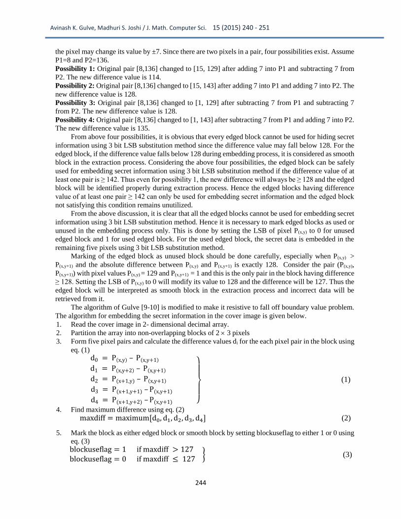
the pixel may change its value by ±7. Since there are two pixels in a pair, four possibilities exist. Assume
P1=8 and P2=136.
Possibility 1: Original pair [8,136] changed to [15, 129] after adding 7 into P1 and subtracting 7 from
P2. The new difference value is 114.
Possibility 2: Original pair [8,136] changed to [15, 143] after adding 7 into P1 and adding 7 into P2. The
new difference value is 128.
Possibility 3: Original pair [8,136] changed to [1, 129] after subtracting 7 from P1 and subtracting 7
from P2. The new difference value is 128.
Possibility 4: Original pair [8,136] changed to [1, 143] after subtracting 7 from P1 and adding 7 into P2.
The new difference value is 135.
From above four possibilities, it is obvious that every edged block cannot be used for hiding secret
information using 3 bit LSB substitution method since the difference value may fall below 128. For the
edged block, if the difference value falls below 128 during embedding process, it is considered as smooth
block in the extraction process. Considering the above four possibilities, the edged block can be safely
used for embedding secret information using 3 bit LSB substitution method if the difference value of at
least one pair is ≥ 142. Thus even for possibility 1, the new difference will always be ≥ 128 and the edged
block will be identified properly during extraction process. Hence the edged blocks having difference
value of at least one pair ≥ 142 can only be used for embedding secret information and the edged block
not satisfying this condition remains unutilized.
From the above discussion, it is clear that all the edged blocks cannot be used for embedding secret
information using 3 bit LSB substitution method. Hence it is necessary to mark edged blocks as used or
unused in the embedding process only. This is done by setting the LSB of pixel P(x,y) to 0 for unused
edged block and 1 for used edged block. For the used edged block, the secret data is embedded in the
remaining five pixels using 3 bit LSB substitution method.
Marking of the edged block as unused block should be done carefully, especially when P(x,y) >
P(x,y+1) and the absolute difference between P(x,y) and P(x,y+1) is exactly 128. Consider the pair (P(x,y),
P(x,y+1)) with pixel values P(x,y) = 129 and P(x,y+1) = 1 and this is the only pair in the block having difference
≥ 128. Setting the LSB of P(x,y) to 0 will modify its value to 128 and the difference will be 127. Thus the
edged block will be interpreted as smooth block in the extraction process and incorrect data will be
retrieved from it.
The algorithm of Gulve [9-10] is modified to make it resistive to fall off boundary value problem.
The algorithm for embedding the secret information in the cover image is given below.
1. Read the cover image in 2- dimensional decimal array.
2. Partition the array into non-overlapping blocks of 2 3 pixels
3. Form five pixel pairs and calculate the difference values di for the each pixel pair in the block using
eq. (1) d0 = P(x,y) – P(x,y+1)
d1 = P(x,y+2) – P(x,y+1)
d2 = P(x+1,y) – P(x,y+1) d3 = P(x+1,y+1) – P(x,y+1)
d4 = P(x+1,y+2) – P(x,y+1)
}
(1)
4. Find maximum difference using eq. (2)
maxdiff = maximum[d0, d1, d2, d3, d4] (2)
5. Mark the block as either edged block or smooth block by setting blockuseflag to either 1 or 0 using
eq. (3)
blockuseflag = 1 if maxdiff > 127 blockuseflag = 0 if maxdiff ≤ 127
} (3)

Avinash K. Gulve, Madhuri S. Joshi / J. Math. Computer Sci. 15 (2015) 240 - 251
245
6. If blockuseflag = 1 and maxdiff > 141, mark the edged block as used block by setting LSB of the
pixel P(x,y) to 1. Hide 3 secret message bits in each of the remaining five pixels in the block and go
to step 19.
7. If blockuseflag = 1 and 128 ≤ maxdiff ≤ 141 then mark the edged block as unused block by setting
the LSB of pixel P(x,y) to 0 using the following conditions and go to step 19.
a. If |P(x,y)-P(x,y+1)| = 128 and P(x,y) = 255 then subtract 1 from P(x,y) and P(x,y+1) maintaining the
difference between P(x,y) and P(x,y+1) to 128.
b. If |P(x,y)-P(x,y+1)| = 128 and P(x,y) > P(x,y+1) and P(x,y) < 255 then add 1 to P(x,y) if P(x,y) is a odd
value else do not change its value.
c. If |P(x,y)-P(x,y+1)| > 128, set the LSB of pixel P(x,y) to 0.
8. If blockuseflag = 0, perform the following steps to embed the secret information in the five pixel
pairs of the block using PVD approach.
9. Use di where i = 0,1,2,3,4 to locate suitable range Ri,k in the designed range table. Use this
range to calculate number of bits ti to be embedded in each pair Pi. Then calculate the average of
the bits using eq. (4)
𝐴𝑣𝑔 = ∑ 𝑡𝑖4𝑖=0
5 (4)
10. Calculate the revised difference d1i where i = 0,1,2,3,4 as |d1i| = remainder(|di|/2avg) so that
d1i ≤ 2avg
11. Calculate the offset difference ODi as ODi = di – d1i for each pixel pair.
12. Use d1i where i = 0,1,2,3,4 to locate suitable range Ri,k in the designed range table.
13. Compute the number of bits ti that can be embedded in each pair using the corresponding range
given by Ri,k. The value ti can be estimated from the width wk of Ri,k , which is given by ti = log2wi,k
where width wi,k= ui,k li,k 1 and ui,k and li,k are upper and lower boundaries of the range Ri,k.
14. Read ti bits from the binary secret data and transform the bit sequence into a decimal value b.
15. Calculate the new difference value d’i using eq. (5)
di′ = ODi + li,k + bi if di ≥ 0
di′ = −(ODi + li,k + bi) if di < 0
} (5)
16. Modify the values of pixels in pixel pair Pi by using eq. (6)
n n+1 n n+1
m P’ , P’ =
2 2 P - , P +
m
(6)
where Pn and Pn+1 represents two pixels in the pair Pi and m is the difference between di and d’i.
17. Select the pair with minimum m as the reference pair and use this pair to adjust the values of
pixels of the other four pairs. The value of the common pixel is given by P’n of the reference pair.
Modify value of other pixels P’n+1 of each pair such that the new difference d’i for each pair will
remain unchanged. Thus new values are assigned to remaining four pixels in the block.
18. Check the new pixel values for fall off boundaries i.e. check whether all the pixel values are within
the range 0 to 255. If not, modify the pixel values of each pair preserving the difference value.
a. Find out smallest of all the pixel values. If smallest value is less than 0, add |smallest| in all
the pixel values in that block.
b. Find out largest of all the pixel values. If largest value is greater than 255, subtract (largest
– 255) from all the pixel values in that block.
c. If fall of boundary problem still persists, then the cover image is not suitable for hiding
secret data.

Avinash K. Gulve, Madhuri S. Joshi / J. Math. Computer Sci. 15 (2015) 240 - 251
246
19. Now, reconstruct the block with modified pixel values.
20. Repeat the embedding process from step 3 to 19 till the message gets embedded in the cover image.
To extract the secret information hidden in the stego image, the image is read as 2D array and
partitioned in the blocks of 2 × 3 pixels. The maximum difference is calculated from the difference values
of five pairs in the block. For the smooth blocks, PVD approach is used to extract secret information
embedded in the pairs. For the edged blocks, LSB of pixel P(x,y) is extracted. If the decimal equivalent of
LSB is 1, 3 LSB’s of each of the remaining five pixels in the block are extracted otherwise the block is
skipped.
The algorithm for extraction of the secret information from the stego-image is given below.
1. Read the cover image in 2- dimensional decimal array.
2. Partition the array into non-overlapping blocks of 2 3 pixels. Keep the partition order same as
data embedding.
3. Calculate the difference values separately for each block in the stego-image using eq. (7)
d0 = P(x,y) – P(x,y+1) d1 = P(x,y+2) – P(x,y+1)
d2 = P(x+1,y) – P(x,y+1) d3 = P(x+1,y+1) – P(x,y+1)
d4 = P(x+1,y+2) – P(x,y+1)
}
(7)
4. Find maximum difference using eq. (8)
maxdiff = maximum[d0, d1, d2, d3, d4] (8)
5. Mark the block as either edged block or smooth block by setting blockuseflag to either 1 or 0 using
eq. (9)
blockuseflag = 1 if maxdiff > 127 blockuseflag = 0 if maxdiff ≤ 127
} (9)
6. If blockuseflag =1 and LSB of pixel P(x,y) =1, extract 3 LSB’s of each of the remaining five pixels
in the block and then go to step 13.
7. If blockuseflag =1 and P(x,y) = 0, skip the block and go to step 13
8. If blockuseflag = 0, perform the following steps
9. Use di where i = 0,1,2,3,4 to locate suitable range Ri,k in the designed range table. Use this
range to calculate number of bits ti that is hidden in each pair Pi. Then calculate the average of the
bits using eq. (1)
10. Calculate the revised difference d1’i where i = 0,1,2,3,4 as d1’i = remainder(di/ 2avg)
11. Use d1’i where i = 0,1,2,3,4 to locate suitable Ri,k in the designed range table
12. After Ri,k is located, li,k is subtracted from d1’i and b’i is obtained in decimal form. b’i represents
the secret information hidden in that pair in decimal form. A binary sequence is generated from b’i
with ti bits where ti = log2wi,k.
13. Repeat steps from 2 to 12 till embedded information gets extracted.
3. Results
For experimentation, a set of 325 grey scale images in tiff format is used. The set has images from
the “The USC-SIPI Image Database (http://sipi.usc.edu/database/)”, the BOSS rank database and images
taken by Canon A45 camera. The images taken from the camera are resized and converted into tiff
format. The images from BOSS rank database are converted into tiff format and images having minimum
and maximum pixel values close to boundary values are selected from BOSS rank data base. The text
files covering the full hiding capacity of cover image are generated randomly and used as secret
information.
The statistics showing the number of edged blocks, used edged blocks and unused edged blocks is
shown in Table 1. For the BOSS rank image set with 1000 images, the average used blocks are 150 and

Avinash K. Gulve, Madhuri S. Joshi / J. Math. Computer Sci. 15 (2015) 240 - 251
247
average unused blocks are 124.
Table 1 Statistics of used and unused blocks for standard images
Cover Image Total edged blocks
Used Edged blocks
Unused Edged blocks
Elaine 0 0 0
Couple 26 6 20
Sailboat 68 41 27
Baboon 217 107 110
Lena 23 8 15
Tank 0 0 0
Peppers 114 79 35
Barbara 121 36 85
Boat 136 87 49
The hiding capacity of the cover image and PSNR value obtained after embedding secret data in
the cover image are compared with Mandal’ method [7] , Wang’s method [8] and Gulve’s method [10]
method. The comparison is shown in table 2.
Table 2. Comparison of hiding capacity (in bytes)
Cover image
Mandal’s PVD Method [7]
C M Wang’s Method [8]
Gulve’s Method[10]
Proposed method
Capacity PSNR Capacity PSNR Capacity PSNR Capacity PSNR
Lena 51370 40.61 51219 44.1 81631 42.86 81598 42.26
Baboon 57583 36.67 57246 40.3 82116 41.99 81864 39.70
Peppers 51107 40.61 50907 43.3 81650 42.80 81577 42.19
Elaine 51070 41.47 51074 44.8 81603 42.42 81603 42.13
Boat 52631 39.04 52635 42.1 81699 42.31 81581 41.63
Figure 4 shows the cover images and the corresponding stego images obtained using the proposed
method. The cover and the stego images are indistinguishable by human visual system.

Avinash K. Gulve, Madhuri S. Joshi / J. Math. Computer Sci. 15 (2015) 240 - 251
248
Cover image Stego image
Figure 4 Cover and stgeo images
Figure 5 shows the histogram of the cover and stego images obtained using the proposed method.
It can be observed that the shape of the histogram is preserved after embedding the secret data.
Cover image Stego image
Figure 5 Histogram of cover and stego image
The pixel values of cover image are subtracted from stego image and histogram is plotted for the
difference values. This histogram is shown in Figure 6. It can be observed that most of the difference
value lies between 15 and -15. This proves that the deviation in the pixel values of cover image is very
small even after hiding the secret information utilizing the full hiding capacity. Hence the proposed
method is robust against histogram analysis attack.
Figure 6 Difference histogram
Text files, having size in multiple of 10 Kb are embedded in lena.tiff. The stego images so obtained
are tested under the RS steganalysis [11]. It is observed from Figure 7 that the difference between RM
and R-M, SM and S-M is very small. The rule RM R-M and SM S-M is satisfied for the output images. So
the proposed method is secure against RS attack.

Avinash K. Gulve, Madhuri S. Joshi / J. Math. Computer Sci. 15 (2015) 240 - 251
249
Figure 7 RS Diagram
PSNR, MSE and Universal Quality Index (Q) [12] are the most common metrics used for
evaluating quality of the stego image. PSNR measures the distortion caused by data hiding in the original
cover image. Higher PSNR values are the indication of good quality of the stego image. PSNR is given
by (10) 2
1010
RPSNR= log
MSE
(10)
Mean square error (MSE) is given by (11)
2
1 2,
[ ( , ) ( , )]
*M N
I m n I m n
MSEM N
(11)
where I1 and I2 represents cover image and stego image respectively.
The embedding rate is calculated for each cover image in terms of bpp. The proposed method has
the average embedding rate of ~2.48 bpp. The quality of the stego image is analyzed using PSNR, MSE
and universal image quality index [12]. The universal image quality index measures the structural
distortion occurred during the image degradation process. Table 3 shows the PSNR values, MSE and
universal quality index [12] for different images obtained using proposed method. The PSNR values are
above the threshold of 36 dB and Universal Quality Index (Q) values are close to 1, which proves that
the stego images are visually indistinguishable from original cover images.
The detection rate of the proposed method is calculated using Ensemble Classifiers [13].
Experiments are carried out with the BOSS image data set with 1000 images. 686 SPAM features [14]
are extracted from each image. The proposed method has the detection rate of 0.04 for 0.2 bpp and 0.003
for 0.5 bpp. The detection rate for the proposed method is high as compared to HUGO. But this is obvious
because HUGO [15] uses the detectability map to minimize the embedding impact. Also HUGO uses 1
bit LSB technique for embedding. The proposed method uses PVD approach for embedding which
embeds at least 3 bits in a pair. So for 0.2 bpp embedding rate with cover image resolution 512 x 512,
HUGO uses ~ 52428 pixels where as the proposed approach uses at the most 3496 blocks (~ 20976
pixels). Considering this fact, the high detection rate is justified. It is possible to increase the
undetectability by narrowing the width of sub ranges in the range table. But PVD methods are designed
to provide high payloads (embedding capacity of cover image) and narrowing the width of sub ranges
will violet this motivation of PVD approach.
0
0.1
0.2
0.3
0.4
10 20 30 40 50 60 70 79R
atio
of
R,S
Message size in Kb
RM
R-M
SM
S-M

Avinash K. Gulve, Madhuri S. Joshi / J. Math. Computer Sci. 15 (2015) 240 - 251
250
Table 3 Results
Cover Image Hiding Capacity
(Bytes)
PSNR MSE Q
Elaine 81603 42.13 3.98 0.92
Couple 81620 41.72 4.38 0.93
Sailboat 81696 41.32 4.80 0.91
Baboon 81864 39.70 6.98 0.97
Lena 81598 42.26 3.87 0.85
Tank 81595 42.43 3.71 0.93
Peppers 81577 42.19 3.92 0.87
Barbara 81827 40.50 5.80 0.89
Boat 81581 41.63 4.47 0.92
4. Conclusion
The image steganography methods that use LSB method to hide secret information are not prone
to fall of boundary problem. But fall of boundary problem is common for the steganography method that
uses pixel value differencing approach to hide secret information. The problem becomes severe for the
images when the pixel values in the block are close to boundaries making the image unsuitable for hiding
the secret information. Hence there is need of careful selection of cover images when PVD
steganography is used. The proposed method provides a solution for the fall off boundary value problem.
Data hiding capacity, quality of stego image and security are the important factors of the
steganography system. The proposed method not only provides a solution for fall off boundary problem
but also provides improvement in the data hiding capacity and security of secret data. The improvement
in the data hiding capacity is made possible by taking a larger block size of 2 × 3 pixels. The block of 2
× 3 pixels helps in increasing the number of pairs which in turn provides increased data hiding capacity.
Experimentally it is verified that 2 × 3 is the optimum block size and if the block size is further increased,
it affects the performance of the steganography system.
The proposed method modifies the difference value before using it for hiding secret information.
This modified difference value is used to hide secret information. Thus during extraction, the actual
difference value do not stand for the secret information and it is not possible to extract correct secret
information hidden in the pair unless the difference value if modified again. The security is further
improved by combining PVD and LSB steganography methods. All the edged blocks are not used for
hiding secret information. Instead, on the basis of difference, the edged blocks are selected for hiding
secret information using LSB substitution method. Identification of edged block used for hiding secret
information will be a challenging task. Thus, even in case of detection of steganography, extraction of
secret information from the stego image will be a difficult task.
The proposed method also improves the PSNR values. Experimental results prove that the
proposed method passes the visual attack, Histogram Analysis attack and RS steganalysis. The
improvement in PSNR values is due to two reasons- the number of bits embedded in each pair is limited

Avinash K. Gulve, Madhuri S. Joshi / J. Math. Computer Sci. 15 (2015) 240 - 251
251
to the average value of number of bits to be embedded in each pair of that block and the selection of
reference pair with minimum |m| which results in at least two pixel values to be very close to their original
values after embedding secret data. The good PSNR values are the indication of good quality of stego
images.
Considering the fact that no steganography system is secure against all kinds of steganalysis attacks,
the sender should avoid using standard images available on the internet as cover images. For safe
transmission of secret information, the cover images should be freshly created and should be immediately
destroyed after creating the stego images.
References
[1] Wu D.C., Tsai W.H., “A steganographic method for images by pixel-value differencing”,
PATTERN RECOGN LETT 24 (2003) 1613–1626.
[2] Chang K.C., Huang P, Tu T.M., Chang C.P., “Adaptive Image Steganographic Scheme Based on
Tri-way Pixel-Value Differencing”, In proceedings of the IEEE International conference on
Systems, Man and Cybernetics (ISIC), Montreal, October 7-10 (2007), 1165-1168.
[3] Chang K.C., Chang C.P., Huang P.S., Tu T.M., “A Novel Image Steganographic Method Using
Tri-way Pixel-Value Differencing”, Journal of Multimedia 3 (2008) 37-44.
[4] Liao X, Wen Q.Y., Zhang J., “A steganographic method for digital images with four-pixel
differencing and modified LSB substitution”, Journal of Visual Communication and Image
Representation 22 (2011) 1-8.
[5] M.B. Ould Medeni, El Mamoun Souidi, “A Novel Steganographic Method for Gray-Level Images
With four-pixel Differencing and LSB Substitution”, In the proceedings of the IEEE International
conference on Multimedia Computing and Systems (ICMCS), Ouarzazate, Morocco, 1-4. April 7-
9, (2011).
[6] Khodaei M, Faez K., “New adaptive steganographic method using least significant bit
substitution and pixel-value differencing”, IET Image Processing 6 (2012) 677–686.
[7] Mandal J K, Das D, “Steganography Using Adaptive Pixel Value Differencing(APVD) of Gray
Images Through Exclusion of Overflow/Underflow”, In the proceedings of the Second
International Conference on Computer Science, Engineering and Applications (CCSEA-2012),
Delhi,( 2012) 93-102.
[8] Wang C.M., Wu N.I., Tsai C.S., Hwang M.S., “A high quality steganographic method with pixel-
value differencing and modulus function”, The Journal of Systems and Software 81 (2008) 150-
158.
[9] Gulve A K, Joshi M S., “A Secured Image Steganography Algorithm with Five Pixel Pair
Differencing by Selecting the Common Pixel Randomly”, In the proceedings of the 3rd
International Conference on Computational Intelligence and Information Technology (CIIT),
Mumbai, October 18-19 (2013), 55-61.
[10] Gulve A K, Joshi M S., “An Image Steganography Algorithm with Five Pixel Pair Differencing
and Grey Code”, International Journal of Image, Graphics and Signal Processing, 6 (2014) 12-
20.
[11] Fridrich J, Goljan M, Du R., “Detecting LSB Steganography in Color, and Gray-Scale Images”,
IEEE Multimedia Magazine 8 (2001) 22–28.
[12] Wang Z, Bovik A.C., “Universal Image Quality Index”, IEEE SP letters 9 (2002) 81-84.
[13] Kodovsky J, Fridrich J, Holub V., “Ensemble classifiers for steganalysis of digital media”,
IEEE Transactions on Information Forensics and Security 7 (2012) 432-444.
[14] Pevny T, Bas P, Fridrich J., “Steganalysis by Subtractive Pixel Adjacency Matrix”, IEEE Trans.
on Info. Forensics and Security 5 (2010) 215–224.
[15] Penvy T, Filler T, Bas P., “Using high dimensional image model to perform highly undetectable
steganography”, In the proceedings of 12th International conference on Information Hiding,
Berlin, October 01, (2010).