Embed Size (px)
Citation preview
I I I I I I I I I I I I I I I I I I I
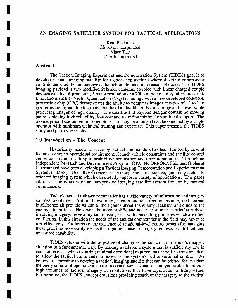
AN IMAGING SATELLITE SYSTEM FOR TACTICAL APPLICATIONS
Abstract
Kent Backman Globesat Incorporated
Vince Tate cr A Incorporated
The Tactical Imaging Experiment and Demonstration System (TIDES) goal is to develop a small imaging satellite for tactical applications where the field commander controls the satellite and achieves a launch on demand at a reasonable cost. The TIDES imaging payload is two modified Schmidt cameras, coupled with linear charged couple devices capable of producing 5 meter resolution at a 700 km polar sun synchronous orbit. Innovations such as Vector Quantization (VQ) technology with a new developed codebook processing chip (CPC) demonstrates the ability to compress images at ratios of 12 to 1 or greater reducing satellite to ground datalink bandwidth, on-board storage and power while producing images of high qUality. The satellite and payload designs contain no moving parts: achieving high reliability, low cost and requiring minimal operational support. The mobile ground station permits operations from any location and can be operated by a single operator with minimum technical training and expertise. This paper presents the TIDES study and prototype results.
1.0 Introduction - The Concept
Historically, access to space by tactical commanders has been limited by several factors: complex operational requirements, launch vehicle constraints and satellite control center constraints resulting in prohibitive acquisition and operational costs. Through an Independent Research and Development Program, cr A INCORPORATED and Globesat Incorporated have been developing' a Tactical Imaging Demonstration and Experimentation System (TIDES). The TIDES concept is an inexpensive, responsive, genuinely tactically oriented imaging system which can directly support a variety of applications. This paper addresses the concept of an inexpensive imaging satellite system for use by tactical commanders.
Today's tactical military commander has a wide variety of information and imagery sources available. National resources, theater tactical reconnaissance, and human intelligence all provide valuable intelligence about the enemy situation and clues to the enemy's intentions. However, the most prolific and accurate sources, particularly those involving imagery, seNe a myriad of users, each with demanding priorities which are often conflicting. In this situation the needs of the tactical commander in the field may never be met effectively. Furthermore, the existence of a national-level control system for managing these priorities necessarily means that rapid response to imagery requests is a difficult and unassured capability.
TIDES sets out with the objective of changing the tactical commander's imagery situation in a fundamental way. By making available a system that is sufficiently low in acquisition costs while requiring minimal operational requirements, it will become practical to allow the tactical commander to exercise the system's full operational control. We believe it is possible to develop a tactical imaging satellite that can be orbited for less than the one-year cost of operating a tactical reconnaissance squadron and yet be able to provide high volumes of tactical imagery at resolutions that have significant military value. Furthermore, the TIDES concept envisions providing much of the imagery to the tactical
1

user in near realtime, with delays of at most a few minutes from observation to viewable and interpretable imagery.
TIDES demonstrates the achievability of these objectives through the design of a small satellite system with the following operational characteristics:
Satellite Type
Spectrum Resolution Coverage
Swath Width Frame Size Frames per Pass Frame Display Time Hard Copy Production Cost
Ima~m~
Visual 5 meters Worldwide (5 day revisit) for a one satellite constellation Worldwide daily coverage for a three satellite constellation 700 km for a 700 KM orbit 60 km (nominal) (selectable within swath) 8-14 (downlink limited) <2 sec Under 1 min per 25 km2 high resolution image Under $15M per satellite including launcher
. The satellite is supported by an inexpensive, transportable ground station capable of receiving, processing, displaying, and printing imagery as well as controlling and monitoring the satellite, and planning and tasking imaging missions. This ground station provides user-friendly support allowing field personnel to exploit the full TIDES capabilities without university technical education or months-long technical training.
TIDES is scaled to provide imagery of 5-meter resolution, a discrimination capability which studies show meets many tactical objectives. In particular, troop movements; marshalling of troops and vehicles in battle fomlations; airfield occupancy; condition of roads, bridges and transportation arteries; occupancy of and activity at berths in seaports; and location, size, and general class of naval vessels are all information elements which can be discerned at this resolution level.
This paper addresses the TIDES operational concept, imaging system, communication system, satellite system, mobile ground station, and discusses the TIDES laboratory prototype
2.0 Operational Concept
The orbit for the TIDES mission is a sun synchronous orbit to facilitate experiment planning since the orbit plane maintains a nearly constant orientation with respect to the sun. The TIDES satellite will observe the earth at the same local time, seeing similar ground illumination, on the daylight half of every orbit. The orientation that the orbit plane makes with the sun determines this local time of observation and is specified as a launch parameter. The TIDES baseline trajectory is circular at an altitude of 700 km and an inclination of 98.19 degrees. From this orbit, the optical system will be able to see any point on the earth between 850 Nand 850 S latitude. The interval between imaging opportunities is a function of latitude, but does not exceed five days.
The concept of operations of the TIDES ground segment with the satellite, payload and operator, is presented in graphic form in Figure 2.1. Shown are the activities of each of these players before, during, and after the "pass" or time when the satellite is visible to the
2
I I I I I I I I I I I I I I I I I I I

- - -
OPERATOR
~NOSTAlIOII
Sl'ACECRAFT
PAYLOAD
- - - - -~ ...... -------PftEPASS ..
IlIIlII!n'OlltO::o POSITION
IIISSIOII PLANIINQ
• STAlION AOS LOS • TARGET AOS LOS • PA. eMD LOAD PREPARED • So(: CliO LOAD PREPARED
POINTS ANTENNAS
• NOT TIME SCALED
•• MORrow. OPERATIONS
IZl .ABNORMAllY
- - - - -ACTIVITIES·
ACQUIRE
SATElU'T'II':
~ .. __ ------- PASS
o S£H5OR A.NOIIAl y .. vot.. lAGE TOO "OK
ra 11JfIH SENSOR OfF f2 S£LEeTS ClAD'- .. E ....
IZl ""RIflES ALARM fl£SOL YEO
& fRAME $VHC~TlON
lI_ssCM ... IIIIII!Ioo-JN(S CIoI)S FOR VElllflCATIDH
IIIIII<xEClITEli ClODS
.00¥IfMJN( PIL .. SiC SicK OA TA
f2l_SCllDfORY£RFOCAlIDH AI...AJW COMM»m EXEc::t.nEO
Figure 2.1 UDES Operations Timelinc for a Typical Pass
- - - - - -.. ~ ...... -----POST PASS
TARGET ACQUISITION
III EXECUTE STORED Pil COIIIIANDS
rL ..... ":D~A~T!'!'A~COl.~l'!E~C'I1~OH~.~200~II~B~.1 .. 1~1I"'1:: .. ~ ..... ]"'S .. :-]

ground station and operator. The system concept of operation requires only a single operator with minimum tech:1ical training and space system expertise to operate the ground station.
Pre-Pass Activities
Operator pre-pass functions are primarily concerned with mission planning. The operator begins with a concept of what he wants the satellite to do, both ill terms of maintaining the health and status (attitude, power, etc.) of the satellite and in terms of the imagery that needs to be collected. This is then supported by the ground segment as he translates these desired objectives into a set of commands and a schedule for uplinking the commands to the satellite. While these planning support functions are discussed in more detail in subsequent sections, lhey basically consist of using the system knowledge about where the satellite is and what it can see to determine when commands can be uplinked, imabery can be acquired, and data can be downlink.!d. The result of the operator interacting with these capabilities is a satellite command plan, ready to be uploaded.
Pass Activities
During the time the satellite is in view of the ground station, most of the activities are taking place in realtime over the now-acti ve ground segment-to-satellite links. The ground segment supports the operator's rea!tirrJe interaction with the satellite by keeping the antennas pointed at it, receiving and transmitting over the command links, and providing realtime translation assistance as the operator "talks" to the satellite. The operator is uploading the previously derived command plan, verifying that the satellite has received the plan correctly, receiving and evaluating data about the satellite's health and status, and dealing with any anomalies that may have occurred while the satellite was out of view. Once these vital housekeeping and commanding chores are complete, the operator can also use the remaining "in-view" time to receive imagery that the satellite has collected in accordance with previously uplinked command plans.
Again, the basic ground station support functions depend on knowledge of where the satellite is and what the operator wants to do. It also provides support in terms of interpreting limits on some state of health data and alerting the operator if the data indicates a sick bird.
Post-Pass Activities
Once the satellite has disappeared from view of the ground station, the operator/ ground segment team returns to the planning mode as described in Pre-Pass activities, but concerned with the next set of objectives for the satellite. This is also the time when the operator must deal with the data that has been downlinked. If the health and status data indicated a sick bird which could not be made well in realtime, the operator and ground station will be reviewing the entire relevant data and command history to determine the cause and likely fix for the anomaly. The payload data is also waiting for attention; the operator will decompress, view, exploit, and print it and/or prepare and send it to another user for exploitation and use. The ground station supports these processes by providing storage, recall, and analysis capabilities for state-of-health data and by providing storage, recall, decompress, display, print, format, and digital data output capabilities for itTlagery.
4
I I I I I I I I I I I I I I I I I I I
1 1 1 1 1 1 1 1 1 1 1 1 1 1 -I 1 1 1 1
Realtime and Non-Realtime Payload Operation Scenarios
Operational scenarios are shown in Figures 2.2(a) and 2.2(b) for a realtime data collection and downloaci zenith pass of approximately 12 minutes in length and for a separate non-realtj{Lle data collection. In this illustration, the ground station is located at Grand Junction, Colorado \see Figure 2.2(a». Prior to the pass, the operator developed mission plans using the payload mission rlanningand analysis system.
The command plan for the realtime pass is shown in Figure 2.2(c). For this revolution of the satellite, the operator's objective was to take as many imag(~s as possible and downlink the images during the zenith pass. After review and approval by the 01'erator. the mission plan was convert~d into commands for uploading to the spacecraft. ;\8 shoWTl in Figure 2.2(c), the plan called for image data to ~ collected, temporarily stored, and transmitted to the ground as quickly as available link tim\~ would permit. A nominal 60 krn x 60 km image takes approximately 8 seconds to colkct. Using a data compression ratio of 12 to ], a single image takes approximately 70 ~econds to downlink to the ground station at 1.::4 Mbps raLes. A total of eight compleIe images were to be transmitted in executing this plan.
In addition to the realtime pass, the operdtor desired to image Tripoli Libya and the surrounding area. Prior to the pass, the mission planning and analysis software identified the imaging opportunities represented by the ground track shown in Figure 2.2(b). The single planned image of 60 km wide by 960 km long uses the entire on-board storage capacity of 200 Mb (at a compression ratio of 12 to 1). After review and approval of the imaging plan (as shown) and the downlinking plan (not shown) by the operator, a timetagged payload command was uploaded (during th~ prss ('ver Grand Junction) for later execution. Although not shown, the downlink of the imagery of this nearly 60,000 square kilometer area would take place during more than one subsequent pass in view of Grand Junction.
\Vhen the spacecraft was positioned for Acquisition of Signal (AOS) on the Figure 2.2(a) pass, the command plan was executed as shown in Figure 2.2(c). First, the operator was alerted, then communications began with the ground station commanding the satellite to downlink health and status data. Payload command uploads were sent and returned to the ground for verification. After ground verification, a command was sent to execute the command load. Throughout the pass, health and status data were periodically downlinked on the UHF channel. The operator viewed and reacted as necessary to the health and status information in near-realtime (no reactions are shown in Figure 2.2(c». As soon as imaging began, the system started downlinking payload data on the X-band channel. Payload data was written directly to hard disk storage for processing after the pass. At the end of the pass, the spacecraft stopped transmission and entered a "quiet" mode until the ground station again came into view. Although not represented in Figure 2.2(c), the Tripoli imaging plan of 2.2(b) would be executed by the satellite based on uploaded time-tagged commands, and the imagery would be stored for later downlink according to the downlink plan.
5

- - -
~ ....
s..:a.ds 15
Fill'" 2.2(a) Re.HI .... 1ma&e Co1lectionand RadolI1
I!umpIe S<r.oario
100 1!j() 200 250
~ ;:::::? I_lAOS: 2-l
~e_
:
3 _""""" IIrd S ..... 00wnIiI\k
" 5 6 t.tJ~-1«I : 7 :;~
300 350
;
,
• • 11""',...;'//// .... · r~
, ................ , ... II 10 : r ..... .:;t/77 /1
• 11 F I-12 : ...... // ./1 , ... 13 ·.lSa1'~C"y
14 r-"""""'/ /..; 15 i t:,\-
400 4SO SOO
,
I·"
:
550
F""", 2.2(b) N",,·ReaHime lmall"
Collection
91PQFP_
600 650 700 750
. fl ......... -:
.. , i......'
.... , .......... • S-C~_on
800
... , ....... ..... ,........ . .. , .......... o GI<U'1d S~'on funcaonI~ t········· ........
: ........... o CCOAaMI'/ .... ......... e:z:zJ ""age<'( Dowoid
......... : .... . .......... , .... ··· .. t
·T Iii ~'///J 11 :T [ .. 1 CoIorodo Spir II' 1. .~-/ 111 ·f}js .... "" i ao ....... - ... -/// 21 : , 22 : : f : l ....... ~""! .//\ 23 '::IBP,,",; 24 : ,., .. ,,;, / /l j
- - - - - - - - - - - - - - - -

I I I I I I I I I I I I I I I I I I I
3.0 Imaging System
An underlying philosophy operative during this study was to keep reliability high and costs low by developing a system with no moving parts. This applies to the imaging system as well as the other satellite subsystems. An all electronic system was developed in which scenes are selected through computer control by activation of selected circuit portions avoiding camera pointing and the failure prone associated mechanisms. Baseline imaging specifications call for the ability to select from the ground track swath an arbitrary 60 km wide segment and to record and store 60 km of its length. A panchromatic visual spectrum system meets the needs of this initial study.
Sensors and Spectral Band
Special applications of an Imaging Subsystem (ISS) may require special spectral sensitivity and selectivity capabilities. For the majority of conceive applications coverage of the visual spectrum will suffice. This study as a baseline is concerned with only considering only visual spectral issues. Linear charge coupled devices (CCO) were studied as candidate sensors. CCO arrays are commercially available in several different packages with differing specifications. In selecting a sensor suitable for the present application, the size and number of photosensing elements and the speed, or data rate of the device, are the main considerations. For sharp, high resolution images, sensors with small pixel size and high data rate are the better choice. Of the more advanced sensors now available, 8 x 8 micron photosensitive areas and 25 mHz data rates are obtainable in linear arrays of 1 x 1024 elements. This array is selected as baseline capability representative of potential sensors.
Optics and Resolution
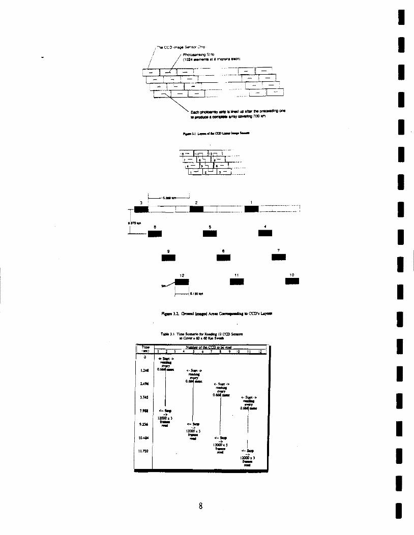
Linear sensor arrays arranged in a continuous row perpendicular to the path of flight permit collecting image data row by row in a push-broom fashion. Such an array geometry allows for the capture of images with many more pixels than possible with a matrix array of sensors. The satellite is a stable platform over the short period of time required to capture and image. As a baseline for this study 5 meter resolution was selected as was a swath width of 700 km and an orbital altitude of 700 km. Each 1024 x 1 CCO sensor therefore will image an area 5.12 km x 5 meter(m). Twelve sensors in a row would image 61.4 km x 5 m. To image the entire baseline swath width requires approximately 140 CCO sensors. The sensor system therefore consists of 140 linear CCOs arranged such that any 12 adjacent sensors can be used to collect an arbitrary 61 km wide image. Coverage of off-track regions is obtained by electronically choosing a suitable set of detectors. This is equivalent to tilting the satellite without any mechanical motion. The use of no moving parts also makes attitude stabilization an easier task.
Commercial CCO sensors come in packages which are much larger than the size of the photosensitive area. To form a continuous photosensitive pixel row, the CCO packages must be staggered as shown in Figure 3.1. This arrangement, however, causes the pixel row to be captured in segments. Many of the segments are captured much later in time requiring the temporary storage of portions of the pixel rows until the completing pixels can be captured. The timing and orientation problems are within the state-of-the-art. As a practical consideration, the array is sectioned into two separate pieces each installed in a camera. Figure 3.2 illustrates the correspondence between the geometry of the CCOs in the focal plane and that of the imaged areas of the ground. The image of 60 km x 60 km is obtained by reading the selected 12 sensors with a time scenario given in Table 3.1. It
7
T • .m ....
I [ - -7~--:'. -_ i!: .. _____ _ I :;: -' - I._~_
. e.:n ~ ~ illiowd \Ct aftllf e.. ~ng one
ID~'~ IIII"IYGIMItng 700 10m
1--.. 5 - 4 -9 e 1 - - -
11 10 - -I = 0
1.l6I
1.4" '.1~
1.9. 9.lJ6
10.414
11.132
T ..... '.I n-s..n.r..r_,llCCl)s-t .. c.......iIO.iIOIC!DS_
I 1 ) 4 l 6 1 I 9 10 II
.s.n .> .-.
'r <- SIIIt·> .-.. o.~~
<. Sw!.> .-.. o~~
<·s ..... ·'" .-. <-..., 0.::'"
-> 1211)0. , rr- <--.... ->
l2000d rr-.... <---. llOllI,. ,
rr- <--.... -> 1211)0. , rr-....
8
12
I I I I I I I I I I I I I I I I I I I

I I I I I I I I I I I I I I I I I I I
should be noted that the choice of the beginning CCD is arbitrary. This time scenario is determined assuming a CCD package size 3 cm x 1.5 cm, the distance traveled by the satellite in space (7.5 km/sec), and the other baseline parameters mentioned earlier.
Full swath imaging requires approximately a 52 degree view angle for 700 km width at 700 km height. This requirement can be met with two modified Schmidt cameras. Each would then be required to image up to 13 degrees off axis. Cameras of this capability are not simple, but are within the state-of-the-art. The system is configured with the cameras twisted to span the total field of view on two separate focal planes. Each of the two cameras would be identical, thereby keeping total cost down. The cameras will require atmospheric mirrors and low thermal expansion composites to achieve the required results.
Image Data Compression
Without compression, a 60 km x 60 km scene is captured in a 12,000 x 12,000 matrix of picture elements or pixels. For a single un-compressed image with 8 bits per pixel, approximately 1.2 x 109 bits of information are generated. Processing images of this size would require extensive resources to both store and transmit them. Image compression could significantly improve the performance of the ISS if it can be accomplished in a manner so as to not degrade the image quality beyond an acceptable amount.
At present, the technology to compress imagery by twelve to one and provide a high quality companded (Compressed and exPANDED) image is available. Algorithms have been developed and implemented which use Vector Quantization (VQ) as the principle means of compression. (1) Compression by a factor of twelve to one improves performance by reducing transmission time to 1/12 of the original time and reduce memory requirement by the same factor.
Vector Quantization compression is accomplished by dividing the image into groups of pixels m x n refereed to as vectors. Typically, m and n have the same value although it is not required. Each pixel in the vector is represented by a k bits of information. Instead of transmitting the mnk bits of information contained in the vector, a representation of the vector is transmitted. The representation can be selected from a list of candidate vectors comprising a "codebook". If the representation is of sufficient quality to be acceptable and it can be specified by fewer bits than the original vector, then a "compression" of the data has occurred. There are several algorithms and variations on the algorithms which provide compression. Consider the following example of Mean Residual Vector Quantization (MRVQ) for a 5 x 5 vector with 8 bits per pixeL Each vector is originally represented by 200 bits of information. MR V Q first removes the mean value of the vector from each pixel value and for illustrative purposes assume the mean is represented by 6 bits of information. Then, from a codebook of 1,024 entrees, the entry which best matches the residual vector is selected. Ten bit are required to uniquely specify one of the codebook entrees. The 6 bit mean and the 10 bit codebook address result in 16 bits representing the original 200 bits of image information. A compression ration of better than 12 to 1 is the result. The image is reconstructed by following the reverse process. Using the address, the appropriate residual vector is selected and to it is added the mean value. If the companded images are of good enough quality, then significant savings in transmission times and memory requirements have been achieved.
9

The key to effective VQ compression are the code books which are used. An algorithm developed at Stanford generates codebooks using images that represent the types of imagery to be compressed. (2) Using these codebooks, VQ forms high quality companded images. Tests have shown these codebooks have a wide range of applicability (i.e., they are robust).
The computational requirements to select from a codebook the best match for a particular vector are stringent. Without special provisions to meet these requirements, VQ would not be a viable scheme for ISS applications. The heart of the compressions system is a specialized integrated circuit refereed to as the Codebook Processing Chip (CPC). The CPC provides the practical means of compressing satellite imagery and make the present ISS concept feasible. The CPC was developed at Utah State University for general purpose image compression applications. (3) The chip contains several specialized high speed parallel processors which are estimated to be equivalent to multiple transputers (10 MIPS Processors) in this application.
Image Storage/Retrieval
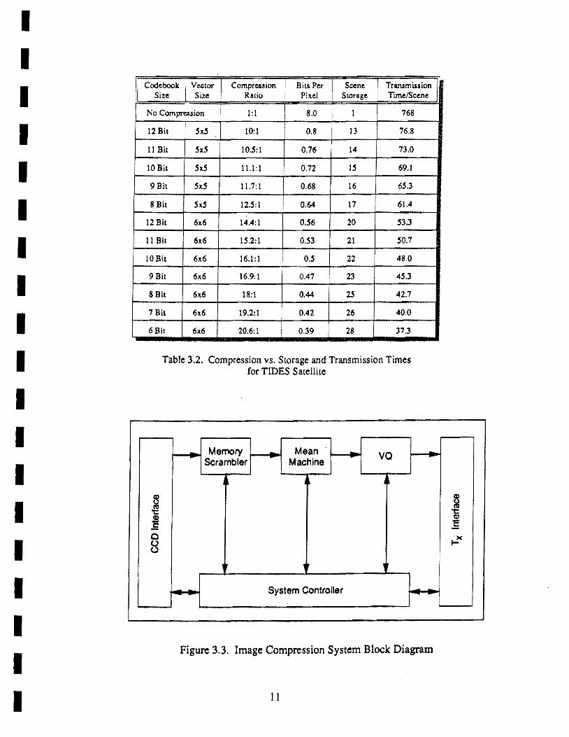
Image storage will be accomplished using semiconductor memory as opposed to a tape recorder or other storage device which has moving parts. For TIDES, 200 megabytes of CMOS static random access memory was selected. When not being accessed, CMOS SRAM consumes approximately 50 micro-Watts per 1 megabyte integrated circuit. Therefore,the entire 200 megabyte memory can hold images for only 0.1 Watts power consumption. Assuming an 8 bit mean vector value, Table 3.2 shows the effect of choosing various code book sizes and vector sizes on storage capacity assuming 200 megabytes of memory and transmission time for 1.54 megabytes/sec data rate. This clearly points out the tremendous advantage gained by using image compression. In this example, a single scene 12,000 x 12,000 x 8 bits requires 144 megabytes and compression of 10:1 permits the storage of 13 images in the same memory space. Ten to twelve bit codebooks produce superior quality images, whereas the eight and nine bit codebooks produce good quality images. Smaller code books generate images which begin to acquire a blocky appearance.
Image System Control
The image compression system block diagram is shown in Figure 3.3. Four major block and two interfaces compose the system. The first interface joins the image compression circuitry to the optics. This interface will manage the flow of raw data from the CCD. The first block contains the memory scrambler whose function it is to accept the sequential and time shifted raw data from the CCDs and format them into vectors. The vector data moves to the next block, the mean-machine which computes the mean value of the vector, and then strips the vector of this value. The mean value and a residual vector is output. The residual vector flows to the vector quantizer block which searches the codebook and determines the "best" representation of the vector residual. The VQ output is an address pointing to the selected code book entry. The mean value and codebook address are combined to yield the compressed vector image data and in tum is either stored for later processing or transmitted immediately.
The imaging system will permit experimentation with effects of changing various system parameters. Codebooks for various sizes, which also change the amount of image compression, can be uploaded and tried. Codebooks designed for specific types of images can be tested. Several code books can be stored in memory and one of them optimized for the specific image and then selected for use while "on the fly".
10
I I I I I I I I I I I I I I I I I I I
I I I I I I I I I I I I I I I I I I I
Codeboolc Vector Compression I
Bits Per I Scene Transmission Size Size Ratio Pixel i SLOrage TimelScene
No Compression 1 :1 8.0 I 1 768
12 Bit Sx5 10:1 0.8 13 76.8
11 Bit SxS 10.5: 1 0.76 14 73.0
10 Bit SxS 11.1:1 0.72 IS 69.1
9 Bit SxS 11.7:1 0.68 16 6S.3
8 Bit Sx5 12.S:1 0.64 17 61.4
12 Bit 6x6 14.4:1 0.S6 20 53.3
11 Bit 6x6 IS.2:1 0.S3 21 SO.7
10 Bit 6l1'.6 16.1: 1 O.S 22 48.0
9 Bit 6l1'.6 16.9:1 0.47 23 4S.3
8 Bit 6x6 18:1 0.44 2S 42.7
7 Bit 6x6 19.2:1 0.42 26 40.0
6 Bit 6l1'.6 20.6:1 0.39 28 37.3
Table 3.2. Compression vs. Storage and Transmission Times for TIDES Satellite
Memory Mean va Scrambler Machine
~ ~
~ .! .5 Q
8 ,r ,
System Controller
Figure 3.3. Image Compression System Block Diagram
II
§ 't: Q)
C
.... )(
4.0 Communication System
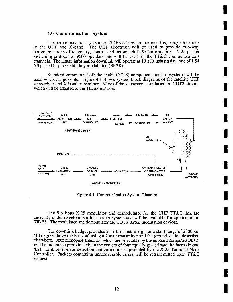
The communications system for TIDES is based on nominal frequency allocations in the UHF and X-band. The UHF allocation will be used to provide two-way communications of telemetry, control and command(TT &C)infonnation. X.25 packet switching protocol at 9600 bps data rate will be used for the TT &C communications channels. The image infonnation downlink will operate at 10 gHz using a data rate of 1.54 Mbps and bi-phase shift key modulation (BPSK).
Standard commercial-off-the-shelf (COTS) components and subsystems will be used wherever possible. Figure 4.1 shows system block diagrams of the satellite UHF transceiver and X-band transmitter. Most of the subsystems are based on COTS circuits which will be adapted to the TIDES mission.
ON-BOARD COMPUTER D.E.S. TERMINAL 70 t.t-!z -- RECEIVER -
.... ... ENCRYPTION........ NODE ........ IFMODEM
SERIAL PORT UNrT CONTROLLER 9.6 KbpS ........ TRANSMriTER --
UHF TRANSCEIVER
UHF
TIR SWrTCH
1 of 4 ANT.
ANTENNAS ~
~. CONTROL·················· .... " ............................................ " ...... ..
IMAGE
DATA D.E.S. CHANNEL ANTENNA SELECTOR ------..... ENCRYPTION ___ SERVICE _____ MODULATOR ____ AND TRANSMriTER 1.536 Mbps UNrT UNIT 1 OF 8,6 Watts
X-BAND TRANSMITTER
Figure 4.1 Communication System Diagram
ANTENNAS
The 9.6 kbps X.25 modulator and demodulator for the UHF TT&C link are currently under development for another system and will be available for application to TIDES. The modulator and demodulator are COTS BPSK modulation devices.
The downlink budget provides 2.1 dB of link margin at a slant range of 2300 km (10 degree above the horizon) using a 2 watt transmitter and the ground station described elsewhere. Four monopole antennas, which are selectable by the onboard computer(OBC), will be mounted approximately in the centers of four equally spaced satellite faces (Figure 4.2). Link level error detection and correction is provided by the X.25 Tenninal Node Controller. Packets containing unrecoverable errors will be retransmitted upon TT &C request.
12
I I I I I I I I I I I I I I I I I I I
I I I I I I I I I I I I I I I I I I I
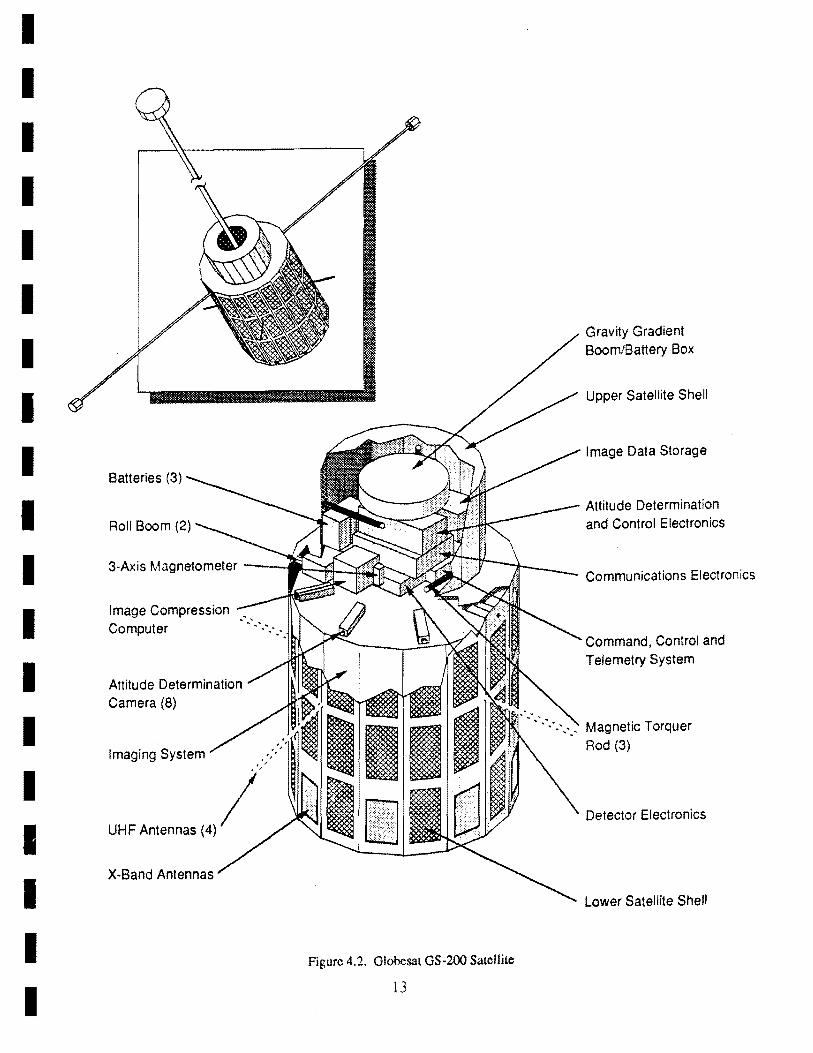
Batteries (3)
3·Ax isM ag netometer ---.I\::-::;;J.-=::C2@
Image Compression Computer
Attitude Determination Camera (8)
Imaging System .#~#t# , '
UHF Antennas (4) /'
Figure 4.2. Globesat GS·2oo Satellite
13
Gravity Gradient Boom/Battery Box
Upper Satellite Shell
Image Data Storage
Attitude Determination and Control Electronics
Communications Electronics
Command, Control and Telemetry System
Magnetic Torquer Rod (3)
Detector Electronics
Lower Satellite Shell
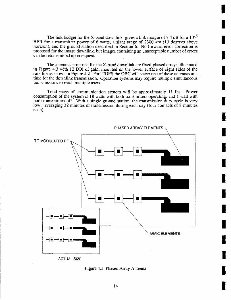
The link budget for the X-band downlink gives a link margin of 7.4 dB for a 10-5 BER for a transmitter power of 6 watts, a slant range of 2300 km (10 degrees above horizon), and the ground station described in Section 6. No forward error correction is proposed for the image downlink, but images containing an unacceptable number of errors can be retransmitted upon request.
The antennas proposed for the X-band downlink are fIxed-phased arrays, illustrated in Figure 4.3 with 12 DBi of gain, mounted on the lower surface of eight sides of the satellite as shown in Figure 4.2. For TIDES the aBC will select one of these antennas at a time for the downlink transmission. Operation systems may require multiple simultaneous transmissions to reach multiple users.
Total mass of communication system will be approximately 11 lbs. Power consumption of the system is 18 watts with both transmitters operating, and 1 watt with both transmitters off. With a single ground station, the transmission duty cycle is very low: averaging 32 minutes of transmission during each day (four contacts of 8 minutes each).
PHASED ARRAY ELEMENTS
TO MODULATED RF
MMIC ELEMENTS
ACTUAL SIZE
Figure 4.3 Phased Array Antenna
14
I I I I I I I I I I I I I I I I I I I
I I I I 1 I I I I I I I I I ·1 I I I I
5.0 Satellite System
The proposed push-broom type imagining requires a 3-axis stabilized system. TIDES gravity gradient (GG) stabilization subsystem is similar to one developed by GSI for GSlOO satellite (4). Augmenting this system with three magnetic torque rods and a magnetometer will provide attitude control within ±20.
A GG three-axis stabilized satellite must satisfy the mass moments of inertia criteria,
Ipitch> Irol!> Iyaw
To satisfy the inertial criteria for TIDES, one boom paralleling the yaw axis (described in the next paragraph) and two booms paralleling the roll axis (positive and negative of the satellite velocity direction) will be deployed. The rooms take the form of tip masses attached to furled metal strips which can be stowed in relatively small volumes within the spacecraft and then deployed to full length upon command. Final boom specifications are dependent on the telescope design and mounting requirements.
The 'yaw' boom will be mounted on the top surface of the satellite. The mechanism is a compactly stowed boom system of furled metal strips which allows the boom-tip-mass to be deployed on command. The battery box is used as the boom-tip mass. Figure 4.2 shows the satellite with deployed booms.
Three magnetic torque rods provide attitude correction torques. Correction torques are used to effect changes in orientation, produce small impulses for damping residual libration motions, and to control the yaw angle about the local vertical. Our analysis shows that with the magnetic torquing capability the satellite can be captured from any initial launch orientation and accelerations into proper orientation for boom extension and entry into a gravity-gradient stabilized mode. Once the booms are extended residual motion can be damped to small steady-state values. Correction torques produced by the torquing rods are strong enough to rotate the satellite 1800 in the event of inverted orientation. If the booms were extended in an inverted stabilization, several progressive correction torques, one after the other, can invert the satellite to the proper orientation.
Satellite attitude will be sensed by a system of eight CCD pin-hole video cameras. The system, which was also developed by GSI for the GS 100, determines the orientation of the satellite by sensing both Sun and Earth horizon (5). The resolution of the cameras allows an accuracy of ±O.2° for the attitude detennination.
Primary power for the satellite will be derived from solar cells mounted on the exterior of the satellite. A total of 6720 solar cells are mounted on 96 panels, each consisting of 2 chains of 35 cells each. The average power generated by the solar cells is about 85 watts. The energy will be deposited into 6 separate batteries consisting of 6 Gates lead-acid D size Cells with 2.1 Volts per cell and 2.5 Ampere-hours capacity.
Batteries will be placed in the main satellite structure and in the gravity gradient tip mass assembly. The batteries provide an on-board storage capability for excess energy produced by the solar cells, a means for powering the satellite during periods of eclipse and additional capacity for periods of peak energy usage.
15

This is enough power to operate for more than seven orbits. The power system will therefore provide the power required by TIDES with 600% battery redundancy and 300% solar cell redundancy. All solar chains as well as each of the batteries will be diode isolated so that individual solar cell chains and batteries can be taken out of the system in case of failure. Battery reconditioning circuits are also provided.
The satellite is an extended aS200, one of several standard models designed and built by aSL All these models are constructed as a right cylinder of several sides. This simple basic design is inherently flexible since by simple modifications the satellite family can be scaled to sizes compatible with various mission requirements and/or available launchers. The satellite bus proposed for TIDES is scaled to a 16-sided cylinder, 42 inches in diameter, stepped in at 52 inches of length to a 12-sided cylinder 32 inches in diameter and 18 inches long. This shape and size fits into the Pegasus launch vehicle and accommodates the TIDES mission payload. Figure 4.2 illustrates the layout of all satellite subsystems, and Table 5.1 summarizes the satellite specifications relevant to TIDES mission.
Mechanical
Electrical:
Table 5.1 Satellite Mission Specifications
Mass: Vibration limits:
system Acceleration limits:
Attitude control: Attitude determination:
Thermal control: Temperature ranges:
Temperature fluctuation:
Total power available: Power consumption
Imaging system: Image Compression:
Housekeeping sensors: Attitude sensing: Attitude control:
Attitude processing: Communications system:
440lbs >imposed by launching
>imposed by launching system
±2° ±O.2° Passive Near Room Temperature <±loK
Average of 85W
Maximum 34.5W <lOW 1.87W 2.8W 3W 30W 18Wpeak
Pegasus launch capability limits the payload mass launched into the TIDES baseline orbit to 440Ibs. Aluminum honeycomb is utilized in the fabrication of the satellite structure to help in maximizing strength while minimizing mass.
Thermal design of the satellite will be such that temperature gradients during lightdark orbital cycles are minimized, especially for the optical system. Preliminary thermal analysis shows that the satellite aluminum structure and thermal mass minimize temperature gradients across the satellite payload area. More control over the temperature of the optical system can be exercised by insulating it with a thin thermal blanket with a reflective surface.
Larger thermal gradients are predicted at the exterior surfaces. This is of concern only when solar cell temperature is allowed to rise above the point at which the cell efficiency starts declining. Our preliminary thermal analysis indicates that white coating for
16
I I I I I I I I I I I I I I I I I I I
I I I I I I I I I I I I I I I I
I
the exposed surfaces of the aluminum panels will minimize temperature swings and keep solar cell temperature within acceptable limits (2800±200 ).
The TIDES telemetry and command subsystem design is derived from an existing OS100 system. The On-Board Controller (aBC) hardware has been built using very low power CMOS technology to minimize its power requirements. The aBC is interfaced to housekeeping (HK) sensors and other devices, including magnetorquer rods for correcting the attitude of the satellite. The proposed system provides 128 8-bit analog input channels for monitoring voltages, currents, and temperatures. Ninety-six outputs are available for digital control; 40 of these are currently unassigned. The aBC also includes several precision interval timers and real-time clock and calendar. Although the proposed CPU (6MHz CMOS 8088) is able to directly address only 1 megabyte(MB) of memory, the aBC can access almost limitless memory using bank-switching techniques.
The TIDES design features 200 MB of dual-ported video memory, in 400 banks of 0.5 MB each for payload data storage; 4 MB, or eight banks of O.S-MB each for HK data storage; and 0.5 MB, including 64 kB of ROM for program codes and arrays that are not bank-switched. Banks that are not in use are powered down to conserve energy.
Software for the aBC is designed around an interrupt driven multitasking kernel. This code is the most critical and complex and therefore resides in ROM to protect it from errors that might be generated by other codes. For failure protection, two copies of the kernel are kept in fusible link ROM. If the copy in use is corrupted by cosmic or other radiation, the software execution will be interrupted. A watchdog timer, a common feature of unattended systems, will restart the software, which in turn will detect that the first copy is bad and use the other. The multitasking kernel provides scheduling of individual tasks, each with its own priority.
Our health and status telemetry philosophy is simple and direct. While data is always available, routine housekeeping (HK) telemetry is only collected and transmitted to the ground segment on demand. A small amowlt of processing is perfonned on board to monitor for power anomalies so that faulty batteries can be taken out of the system, for example. Attitude data is also monitored and stored for downlinking to the satellite operator. The HK data and digital control history are date and time stamped allowing ground-based programs to correlate events on the satellite, e.g., a sudden loss of power associated with turning on a camera. The 128 HK sensors, as a group, can be read each second, or less frequently as conditions demand; an entry to the digital control history is made each time a digital switch is opened or closed. TIDES HK and digital control history data are collected and stored in the bank-switched RAM as "messages" to be forwarded. Each message is a collection of packets. Forward error correction is perfonned on each packet before it is transmitted and the packet is checked when received, guaranteeing valid data. Although the TIDES housekeeping design is complete, the inherent flexibility of our approach allows additional telemetry functions to be accommodated.
6.0 G round/User Segment Overview
The ground/user segment is a self-contained and user-friendly system allowing operational field staff to operate TIDES with minimum training and space system knOWledge. It supports payload mission operations, spacecraft mission operations and antenna tracking and communication functions as shown in Figure 6.1. For TIDES, the spacecraft and the payload operations system have been combined in one workstation. Our
17

..... 00
- - - - -
Slalion Loca/ion HORAO
I,;;;;:;:;:-I-----Pointing Angle's----------l
P,edic1ed Orbrt
ContaCl Schedule
Contact Coverage
Detflfminalion
I Contact & Cove,age t OpportuniIiM
OFF·UHE"
REAL·DUE
.1I1J 'L'::~~~J-----------AcluaJ Tracking Antenna Angle.----f--------
- - - - - - - - - - - - - -

I I I I I I I I I I I I I I I I I I I
design, however, permits these two functions to be implemented in separate hardware suites when required.
The spacecraft operations function includes near-realtime processing of spacecraft health and status data; displaying data in engineering units; performing alarm checking; generating, validating, sending, and verifying spacecraft command uploads; and supporting anomaly resolution. Off-line functions consist of spacecraft contact planning activities including station Acquisition Of Signal (AOS) and Loss Of Signal (LOS) and post-pass analysis processing of data for anomaly resolution.
The payload operations include realtime functions of receiving and logging the data at 1.54 Mbps; generating, validating, sending and verifying pay load commands; generating antenna pointing commands; and displaying the payload sensor status data. Mission planning is an off-line function which consists of target acquisition, sensor/payload command profiles, and mission timeline profiles. Payload data processing, also an off-line function, includes accessing and decompressing TIDES imagery, displaying and printing the image data, outputting images in specific file formats for further dissemination, and archiving the data. Operator capabilities feature zooming, panning, modifying resolution, and selecting data by time, image ID, or location.
Two antennas are provided; one for spacecraft and payload monitoring and commanding in realtime and one for receiving payload data. The spacecraft and payload commanding antenna system is a 450 MHz helix. The communication protocol selected is a modified X.25 operating at 9.6 kbs. The payload data antenna is a 10 GHz circular polarized 3 meter parabolic reflector. Tracking begins with positioning the antenna for AOS prior to a scheduled contact, using azimuth and elevation calculated from predicted orbit parameters. After AOS, the ground station computer periodically feeds antenna azimuth and elevation angles to the antenna controller to maintain spacecraft pointing.
The ground segment workstation is a SUN 4/260 computer with eight megabytes of memory, a 900 Mbyte disk for operating systems, application software and payload data, a 2.3 Gigabyte tape drive for archiving data, a high resolution laser printer for hard copy and a 1024 x 1024 pixel Greyscale SUN monitor for display.
7.0 TIDES Prototype
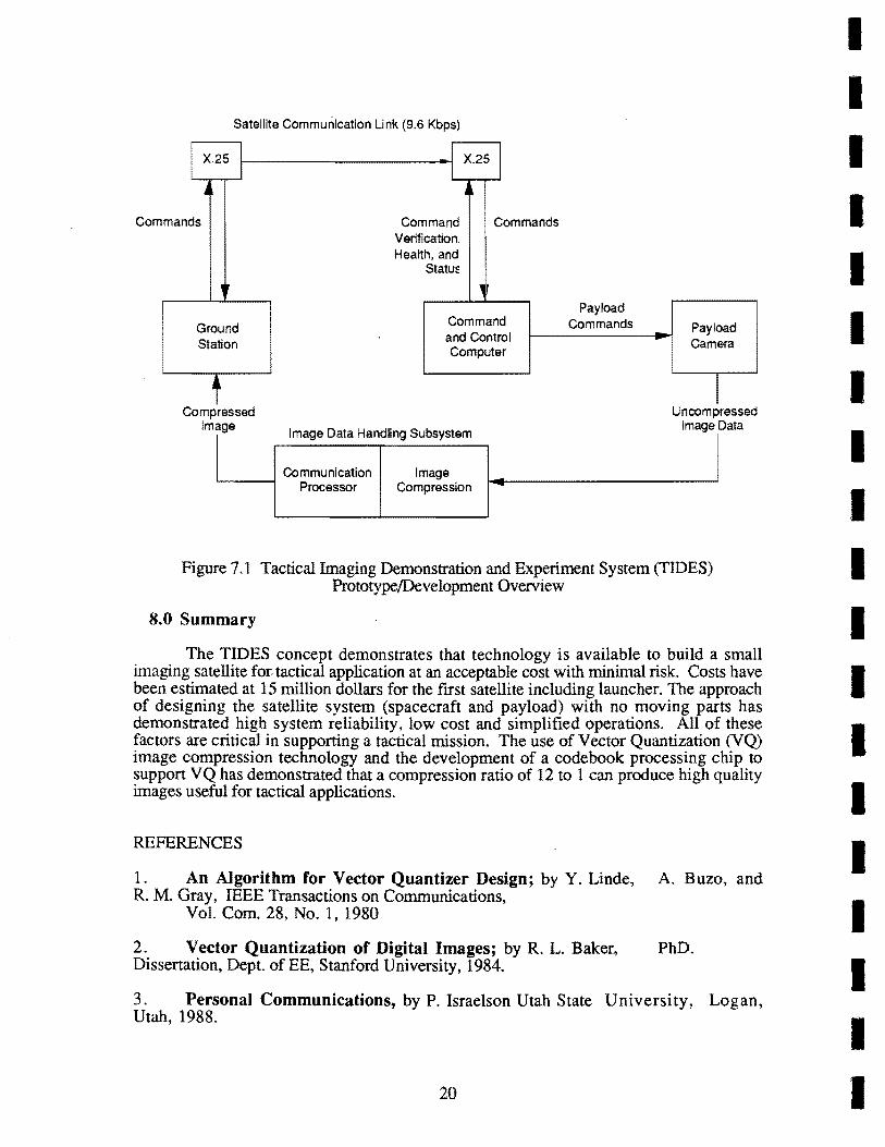
A prototype of various components of the TIDES system was developed as part of an independent Research and Development program. Figure 7.1 illustrates the state of the TIDES prototype.
The objective of the TIDES prototype is to validate the ground station design and operational concept, to demonstrate the image compression technology, to demonstrate and validate the integration of the ground station, the satellite command and control flight computer and the image compression computer subsystem and finally to demonstrate the operations of high quality image with standard COTS equipment.
19
Satellite Communication Link (9.6 Kbps)
I X.25 11-------------11 X.25 I ~ j
Commands
,
Ground Station ,
Compressed Image
Command Commands Verification Hea~h. and
StatuE
Command and Control Computer
mage aa a Ig u y D t H ndrn S bs ste m
Communication Image Processor Compression
Payload Commands Payload
Camera
I Uncompressed
Image Data
Figure 7.1 Tactical Imaging Demonstration and Experiment System (TIDES) Prototype!Development Overview
8.0 Summary
The TIDES concept demonstrates that technology is available to build a small imaging satellite for tactical application at an acceptable cost with minimal risk. Costs have been estimated at 15 million dollars for the fIrst satellite including launcher. The approach of designing the satellite system (spacecraft and payload) with no moving parts has demonstrated high system reliability, low cost and simplified operations. All of these factors are critical in supporting a tactical mission. The use of Vector Quantization (VQ) image compression technology and the development of a code book processing chip to suppon VQ has demonstrated that a compression ratio of 12 to 1 can produce high quality images useful for tactical applications.
REFERENCES
1. An Algorithm for Vector Quantizer Design; by Y. Linde, A. B uzo, and R. M. Gray, IEEE Transactions on Communications,
Vol. Com. 28, No.1, 1980
2. Vector Quantization of Digital Images; by R. L. Baker, PhD. Dissenation, Dept. of EE, Stanford University, 1984.
3. Personal Communications, by P. Israelson Utah State University, Logan, Utah, 1988.
20
I I I I I I I I I I I I I I I I I I I
I I I I I I I I I I I I I I I I I I I
4. A Study for Semi-passive Gravity Gradient, Stabilization of Small Satellites; by A. Siahposh and
A. Sexton, Proceedings AIAA/USU Conference on Small Satellites, 1987.
5. The Development of an Attitude Sensing System for Small Satellites; by W. A. Abdou and S. Tantishanawadi, Proceedings AIAAIUSU Conference on Small Satellites, 1988.
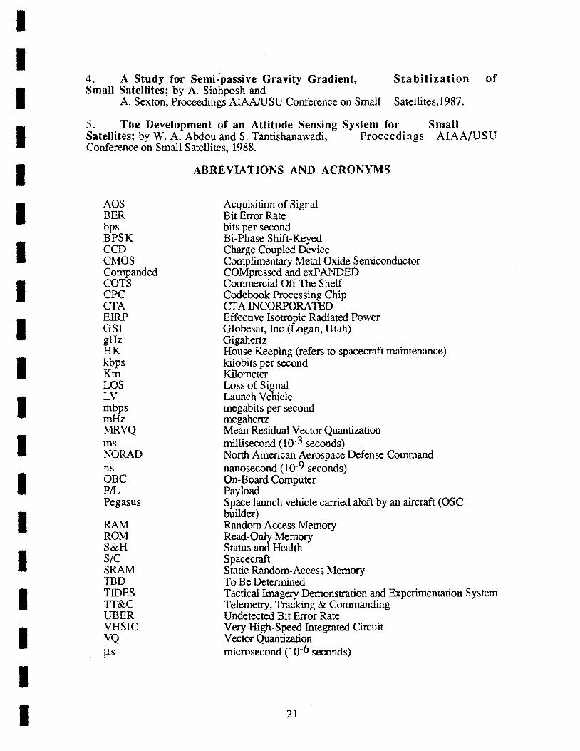
AOS BER bps BPSK CCD CMOS Companded COTS CPC CTA EIRP GSI gHz HK kbps Km LOS LV mbps mHz MRVQ ms NORAD ns OBC PIL Pegasus
RAM ROM S&H SIC SRAM TBD TIDES TI&C UBER VHSIC VQ Ils
ABREVIATIONS AND ACRONYMS
Acquisition of Signal Bit Error Rate bits per second Bi-Phase Shift-Keyed Charge Coupled Device Complimentary Metal Oxide Semiconductor COMpressed and exPANDED Commercial Off The Shelf Code book Processing Chip CT A INCORPORATED Effective Isotropic Radiated Power Globesat, Inc (Logan, Utah) Gigahertz House Keeping (refers to spacecraft maintenance) kilobits per second Kilometer Loss of Signal Launch Vehicle megabits per second megahertz Mean Residual Vector Quantization millisecond (10-3 seconds) North American Aerospace Defense Command nanosecond (10-9 seconds) On-Board Computer Payload Space launch vehicle carried aloft by an aircraft (OSC builder) Random Access Memory Read-Only Memory Status and Health Spacecraft Static Random-Access ?\lemory To Be Determined Tactical Imagery Demonstration and Experimentation System Telemetry, Tracking & Commanding Undetected Bit Error Rate Very High-Speed Integrated Circuit Vector Quantization microsecond (10-6 seconds)
21